EP3184187B1 - Ziehkissenvorrichtung und verfahren zur steuerung der ziehkissenvorrichtung - Google Patents
Ziehkissenvorrichtung und verfahren zur steuerung der ziehkissenvorrichtung Download PDFInfo
- Publication number
- EP3184187B1 EP3184187B1 EP16205284.9A EP16205284A EP3184187B1 EP 3184187 B1 EP3184187 B1 EP 3184187B1 EP 16205284 A EP16205284 A EP 16205284A EP 3184187 B1 EP3184187 B1 EP 3184187B1
- Authority
- EP
- European Patent Office
- Prior art keywords
- fluid
- pressure
- die cushion
- cylinder
- pressure chamber
- Prior art date
- Legal status (The legal status is an assumption and is not a legal conclusion. Google has not performed a legal analysis and makes no representation as to the accuracy of the status listed.)
- Active
Links
Images



Classifications
-
- B—PERFORMING OPERATIONS; TRANSPORTING
- B21—MECHANICAL METAL-WORKING WITHOUT ESSENTIALLY REMOVING MATERIAL; PUNCHING METAL
- B21D—WORKING OR PROCESSING OF SHEET METAL OR METAL TUBES, RODS OR PROFILES WITHOUT ESSENTIALLY REMOVING MATERIAL; PUNCHING METAL
- B21D24/00—Special deep-drawing arrangements in, or in connection with, presses
- B21D24/02—Die-cushions
-
- B—PERFORMING OPERATIONS; TRANSPORTING
- B21—MECHANICAL METAL-WORKING WITHOUT ESSENTIALLY REMOVING MATERIAL; PUNCHING METAL
- B21D—WORKING OR PROCESSING OF SHEET METAL OR METAL TUBES, RODS OR PROFILES WITHOUT ESSENTIALLY REMOVING MATERIAL; PUNCHING METAL
- B21D24/00—Special deep-drawing arrangements in, or in connection with, presses
- B21D24/04—Blank holders; Mounting means therefor
- B21D24/08—Pneumatically or hydraulically loaded blank holders
-
- B—PERFORMING OPERATIONS; TRANSPORTING
- B21—MECHANICAL METAL-WORKING WITHOUT ESSENTIALLY REMOVING MATERIAL; PUNCHING METAL
- B21D—WORKING OR PROCESSING OF SHEET METAL OR METAL TUBES, RODS OR PROFILES WITHOUT ESSENTIALLY REMOVING MATERIAL; PUNCHING METAL
- B21D24/00—Special deep-drawing arrangements in, or in connection with, presses
- B21D24/10—Devices controlling or operating blank holders independently, or in conjunction with dies
- B21D24/14—Devices controlling or operating blank holders independently, or in conjunction with dies pneumatically or hydraulically
-
- B—PERFORMING OPERATIONS; TRANSPORTING
- B30—PRESSES
- B30B—PRESSES IN GENERAL
- B30B15/00—Details of, or accessories for, presses; Auxiliary measures in connection with pressing
- B30B15/08—Accessory tools, e.g. knives; Mountings therefor
-
- B—PERFORMING OPERATIONS; TRANSPORTING
- B30—PRESSES
- B30B—PRESSES IN GENERAL
- B30B15/00—Details of, or accessories for, presses; Auxiliary measures in connection with pressing
- B30B15/16—Control arrangements for fluid-driven presses
Definitions
- the present invention relates to a die cushion device and a method of controlling the die cushion device, and more particularly to a technique of improving responsivity of action of cushion force.
- a die cushion device that controls hydraulic pressure (die cushion force) in a cap side hydraulic chamber of a hydraulic cylinder supporting a cushion pad by using a servo motor for driving a hydraulic pump connected to cap side hydraulic chamber, or a servo valve (refer to Japanese Patent Application Laid-Open No. 2006-315074 (Patent Literature 1) and Japanese Patent Application Laid-Open No. 2006-142312 (Patent Literature 2)).
- a die cushion device comprising a fluid-pressure cylinder configured to support a cushion pad and generate die cushion force while a slide of a press machine descends; a first fluid-pressure circuit configured to supply operation fluid to a cap side fluid-pressure chamber of the fluid-pressure cylinder or discharge the operation fluid from the cap side fluid-pressure chamber; and a second fluid-pressure circuit configured to enable the operation fluid to be prevented from flowing out from a rod side fluid-pressure chamber of the fluid-pressure cylinder, or configured to enable the operation fluid to flow into the rod side fluid-pressure chamber; and a pressurization controller configured to control the first and second fluid-pressure circuits.
- JP 2006 142312 A there is also known method of controlling a die cushion device that includes a fluid-pressure cylinder configured to support a cushion pad and generate die cushion force while a slide of a press machine descends, a first fluid-pressure circuit configured to supply operation fluid to a cap side fluid-pressure chamber of the fluid-pressure cylinder or discharge the operation fluid from the cap side fluid-pressure chamber, and a second fluid-pressure circuit configured to enable the operation fluid to be prevented from flowing out from a rod side fluid-pressure chamber of the fluid-pressure cylinder, or configured to enable the operation fluid to flow into the rod side fluid-pressure chamber.
- a fluid-pressure cylinder configured to support a cushion pad and generate die cushion force while a slide of a press machine descends
- a first fluid-pressure circuit configured to supply operation fluid to a cap side fluid-pressure chamber of the fluid-pressure cylinder or discharge the operation fluid from the cap side fluid-pressure chamber
- a second fluid-pressure circuit configured to enable the operation fluid to be prevented from flowing out from a rod side fluid-pressure chamber
- Patent Literature 3 describes a die cushion mechanism provided with a control device that causes required die cushion force to be properly generated with high responsivity by using slide speed when controlling force of a servo motor for driving the die cushion mechanism.
- Patent Literature 4 describes a control device of a servo motor, the control device achieving high responsivity in terms of control by using command correction means for controlling pressure when force is applied to a driven body to be driven by the servo motor.
- Patent Literature 5 describes a die cushion control device that achieves high responsivity in terms of control by controlling a command to increase pressure, thereby allowing high cushion pressure, required to hold a work, to be promptly generated, and that reduces fluctuations in cushion pressure to enable a product to be favorably formed.
- Patent Literature 6 describes a method of controlling die cushion, the method achieving high responsivity in terms of control by switching between position control and pressure control by position detection of a cushion cylinder, and by the pressure control by a proportion (P)/integration (I) control command and a bias signal.
- the die cushion device described in each of Patent Literatures 1 and 2 causes a problem in that response delay time occurs by the time die cushion force increases to a preset value after a slide collides with a cushion pad (an upper die mounted to the slide collides with the cushion pad supported by a hydraulic cylinder through a material, a blank holder, and a cushion pin) while the slide of a press machine descends, and that the slide descends below an initial position (a die cushion standby position set for each die) of the cushion pad with which the slide collides, while the response delay time elapses.
- a cushion pad an upper die mounted to the slide collides with the cushion pad supported by a hydraulic cylinder through a material, a blank holder, and a cushion pin
- the present invention is made in light of the above-mentioned circumstances, and an object thereof is to provide a die cushion device and a method of controlling the die cushion device, capable of increasing responsivity of action of die cushion force, and of generating desired die cushion force particularly when a cushion pad is positioned at a die cushion standby position, without greatly restricting die structure.
- a die cushion device according to an aspect of the present invention is defined by claim 1.
- the cap side fluid-pressure chamber can be pressurized by preventing the operation fluid from flowing out and supplying pressure fluid to the cap side fluid-pressure chamber of the fluid-pressure cylinder, even before die cushion force is controlled. Then, increasing pressure in the cap side fluid-pressure chamber of the fluid-pressure cylinder before die cushion force control starts enables increase in responsivity of action of the die cushion force.
- the fluid-pressure circuit includes a check valve that prevents operation fluid from flowing out from the rod side fluid-pressure chamber of the fluid-pressure cylinder, and a depressure valve that is provided parallel to the check valve, and the pressurization controller causes the depressure valve to close, before the die cushion force control starts, to prevent the operation fluid from flowing out from the rod side fluid-pressure chamber of the fluid-pressure cylinder.
- the check valve prevents the operation fluid from flowing out from the rod side fluid-pressure chamber of the fluid-pressure cylinder, it enables the operation fluid to flow into the rod side fluid-pressure chamber.
- the operation fluid is allowed to immediately flow into the rod side fluid-pressure chamber.
- the fluid-pressure circuit includes a pilot drive type check valve that prevents operation fluid from flowing out from the rod side fluid-pressure chamber of the fluid-pressure cylinder, and the pressurization controller controls pilot pressure to cause the pilot drive type check valve to close, before the die cushion force control starts, to prevent the operation fluid from flowing out from the rod side fluid-pressure chamber of the fluid-pressure cylinder.
- a die cushion position controller configured to allow operation fluid to be supplied to the cap side fluid-pressure chamber of the fluid-pressure cylinder to raise the cushion pad to a predetermined die cushion standby position after the die cushion force control is finished, and that when the cushion pad is moved to the die cushion standby position by the die cushion position controller, the pressurization controller allows pressure fluid to be supplied to the cap side fluid-pressure chamber of the fluid-pressure cylinder while operation fluid is prevented from flowing out from the rod side fluid-pressure chamber of the fluid-pressure cylinder by controlling the fluid-pressure circuit.
- operation fluid is allowed to flow out from the rod side fluid-pressure chamber of the fluid-pressure cylinder, and when the cushion pad is moved to the die cushion standby position, operation fluid is prevented from flowing out from the rod side fluid-pressure chamber of the fluid-pressure cylinder to enable pressure in the cap side fluid-pressure chamber of the fluid-pressure cylinder to be controlled (switching to pressure control).
- pressure in the cap side fluid-pressure chamber of the fluid-pressure cylinder pressurized by control of the pressurization controller is equal to pressure at which the fluid-pressure cylinder generates a preset die cushion force.
- the pressurization controller causes the cap side fluid-pressure chamber of the fluid-pressure cylinder to be pressurized to the pressure above
- the rod side fluid-pressure chamber of the fluid-pressure cylinder from which operation fluid is prevented from flowing out is also pressurized, and then the cushion pad slightly rises from the die cushion standby position in accordance with an amount of volume compression caused by pressurizing the rod side fluid-pressure chamber.
- the slide descends and collides with the cushion pad to cause the cushion pad to descend together with the slide, and then pressure in the rod side fluid-pressure chamber of the fluid-pressure cylinder is reduced to increase die cushion force.
- the fluid-pressure cylinder When the cushion pad reaches the die cushion standby position, or when the cushion pad descends by an amount of rise caused by pressurization controlled by the pressurization controller to cause pressure in the rod side fluid-pressure chamber of the fluid-pressure cylinder to decrease to pressure in a state where the cushion pad is at the die cushion standby position, the fluid-pressure cylinder generates the preset die cushion force.
- pressure in the cap side fluid-pressure chamber of the fluid-pressure cylinder pressurized by control of the pressurization controller is more than pressure at which the cushion pad is moved to the die cushion standby position as well as less than pressure at which the fluid-pressure cylinder generates the preset cushion force.
- an amount of rise of the cushion pad to be less than an amount of rise of the cushion pad in the case of setting pressure in the cap side fluid-pressure chamber of the fluid-pressure cylinder to pressure at which the preset die cushion force is generated.
- increasing pressure in the fluid-pressure cylinder to the pressure at which the fluid-pressure cylinder generates the preset die cushion force by the time the slide descends to a cushion pad standby position after colliding with the cushion pad, enables the preset die cushion force to be generated at the cushion pad standby position.
- a pressure detector that detects pressure in the cap side fluid-pressure chamber of the fluid-pressure cylinder, a fluid-pressure pump/motor with a discharge port connected to the cap side fluid-pressure chamber of the fluid-pressure cylinder through piping, an electric motor connected to a rotating shaft of the fluid-pressure pump/motor, a die cushion pressure command device that outputs a preset die cushion pressure command, and a die cushion force controller that controls torque of the electric motor on the basis of the die cushion pressure command and pressure detected by the pressure detector to cause die cushion pressure to be a pressure corresponding to the die cushion pressure command.
- the pressurization controller controls torque of the electric motor to control fluid-pressure to be supplied to the cap side fluid-pressure chamber of the fluid-pressure cylinder.
- a die cushion device In a die cushion device according to yet another aspect of the present invention, it is preferable to provide a proportion flow control valve provided in piping connected to the cap side fluid-pressure chamber of the fluid-pressure cylinder, and a die cushion force controller that controls opening of the proportion flow control valve to cause a flow rate of operation fluid discharged from the cap side fluid-pressure chamber of the fluid-pressure cylinder to be controlled to control the pressure in the cap side fluid-pressure chamber of the fluid-pressure cylinder.
- the invention according to yet another aspect is a method of controlling a die cushion device as defined by claim 10.
- a method of controlling the die cushion device it is preferable that there is provided the step of supplying operation fluid to the cap side fluid-pressure chamber of the fluid-pressure cylinder after the die cushion force control is finished to cause the cushion pad to rise to a predetermined die cushion standby position, and that in the step of preventing the operation fluid from flowing out, the fluid-pressure circuit is controlled to prevent the operation fluid from flowing out from the rod side fluid-pressure chamber of the fluid-pressure cylinder when the cushion pad is moved to the die cushion standby position.
- This enables control of pressure in the cap side fluid-pressure chamber of the fluid-pressure cylinder after the cushion pad is moved to the die cushion standby position.
- pressure in the cap side fluid-pressure chamber of the fluid-pressure cylinder pressurized in the step of pressurization is equal to pressure at which the fluid-pressure cylinder generates a preset die cushion force.
- pressure in the cap side fluid-pressure chamber of the fluid-pressure cylinder pressurized in the step of pressurization is more than pressure at which the cushion pad is moved to the die cushion standby position as well as less than pressure at which the fluid-pressure cylinder generates the preset cushion force.
- the die cushion device further includes a die cushion position controller configured to allow operation fluid to be supplied to the cap side fluid-pressure chamber of the fluid-pressure cylinder to raise the cushion pad to a predetermined die cushion standby position after the die cushion force control is finished, and preferable that the method includes the step of controlling the fluid-pressure circuit during press forming performed by lowering the slide and during position control of the cushion pad to enable operation fluid to flow into the rod side fluid-pressure chamber of the fluid-pressure cylinder during the press forming as well as enable the operation fluid to flow out from the rod side fluid-pressure chamber of the fluid-pressure cylinder during the position control.
- the present invention it is possible to control pressure in a cap side (die cushion pressure generating side) fluid-pressure chamber of a fluid-pressure cylinder that generates die cushion force, before the die cushion force control starts. This enables increase in responsivity of action of the die cushion force, and enables a cushion pad not to be greatly raised from a normal die cushion standby position.
- Fig. 1 is a structural view illustrating a first embodiment of the die cushion device according to the present invention.
- a press machine 10 using a die cushion device 100 includes a frame composed of a bed 11, a column 12, and a crown (not illustrated), and a slide 14 that is guided in a vertically movable manner by a guide section 15 provided in the column 12.
- the slide 14 receives driving force transmitted from a slide driving unit (not illustrated), and is moved in a vertical direction in Fig. 1 .
- An upper die 20 is mounted to the slide 14, and a lower die 22 is mounted on a bolster 18 of the bed 11.
- a blank holder (blank holding plate) 102 is disposed in a space between the upper die 20 and the lower die 22, and has a lower side supported by a cushion pad 110 through a plurality of cushion pins 104 and an upper side on which a material 30 is set (brought into contact with).
- the press machine 10 lowers the slide 14 to press-form the material 30 between the upper die 20 and the lower die 22.
- the die cushion device 100 presses the periphery of the material 30 to be press-formed from below.
- the die cushion device 100 includes the blank holder 102, the cushion pad 110 that supports the blank holder 102 through the plurality of cushion pins 104, a hydraulic cylinder (fluid-pressure cylinder) 120 that supports the cushion pad 110 to apply die cushion force to the cushion pad 110, a first hydraulic circuit 130 connected to a cap side hydraulic chamber (cap side fluid-pressure chamber) 120a of the hydraulic cylinder 120, a second hydraulic circuit 140 connected to a rod side hydraulic chamber (rod side fluid-pressure chamber) 120b of the hydraulic cylinder 120, a command device 150, and a controller 160.
- a hydraulic cylinder fluid-pressure cylinder
- the die cushion device 100 has a die cushion force control function of controlling die cushion force generated in the cushion pad 110, and a die cushion position control function of controlling a position of the cushion pad 110.
- the die cushion force control is mainly performed in a die cushion force generating period (during press forming) by the time the slide 14 reaches the bottom dead center after the slide 14 collides with the cushion pad 110 (the upper die 20 mounded to the slide 14 collides with the cushion pad 110 supported by the hydraulic cylinder 120, through the material 30, the blank holder 102, and the cushion pin 104) when the slide 14 of the press machine 10 descends, and the die cushion position control is performed in a period by the time the cushion pad 110 is raised to a standby position (die cushion standby position) set corresponding to a die from a position corresponding to the bottom dead center.
- a standby position die cushion standby position
- the hydraulic cylinder 120 and the first hydraulic circuit 130 serve as not only a die cushion force generator that applies die cushion force to the cushion pad 110, but also a cushion pad lifter that moves up and down the cushion pad 110.
- reference numeral 112 designates a die cushion position detector that detects a position in a stretching direction of a piston rod 120c of the hydraulic cylinder 120 as a position in a lifting direction of the cushion pad 110
- reference numeral 122 designates a die cushion pressure detector that detects pressure in the cap side hydraulic chamber (die cushion pressure generating side hydraulic chamber) 120a of the hydraulic cylinder 120.
- the command device 150 includes a die cushion force (pressure) command device and a die cushion position command device.
- the command device 150 outputs a command value indicating a die cushion force that is a value to be controlled, or die cushion pressure corresponding to the die cushion force during the die cushion force control, and outputs a command value indicating a die cushion position that is a value to be controlled during the die cushion position control.
- the controller 160 includes a die cushion force (pressure) controller and a die cushion position controller.
- the controller 160 outputs a control signal to the first hydraulic circuit 130 on the basis of a command value (command value indicating a die cushion pressure) received from the command device 150 and pressure detected by the die cushion pressure detector 122 during the die cushion force control to cause pressure in the cap side hydraulic chamber 120a of the hydraulic cylinder 120 to be the command value.
- the controller 160 outputs a control signal to the first hydraulic circuit 130 on the basis of a command value (command value indicating a die cushion position) received from the command device 150 and die cushion position detected by the die cushion position detector 112 during the die cushion position control to cause position of the cushion pad 110 to be the command value.
- the first hydraulic circuit 130 controls hydraulic pressure to be released from the cap side hydraulic chamber 120a of the hydraulic cylinder 120 to apply desired die cushion force to the cushion pad 110 during the die cushion force control, and controls an amount of oil flowing into the cap side hydraulic chamber 120a of the hydraulic cylinder 120 to raise the cushion pad 110 to the die cushion standby position during the die cushion position control.
- the first hydraulic circuit 130 and the controller 160 supply pressure oil (pressure fluid) to the cap side hydraulic chamber 120a of the hydraulic cylinder 120 before the die cushion force control starts, and thus serve as a pressurization controller that pressurizes the cap side hydraulic chamber 120a, and its detail will be described later.
- pressure oil pressure fluid
- the second hydraulic circuit 140 (fluid-pressure circuit) prevents hydraulic oil (operation fluid) from flowing out from the rod side hydraulic chamber 120b of the hydraulic cylinder 120, or enables hydraulic oil to flow into the rod side hydraulic chamber 120b.
- the second hydraulic circuit 140 includes a check valve 142 that prevents hydraulic oil from flowing out from the rod side hydraulic chamber 120b of the hydraulic cylinder 120, a depressure valve 144 and a relief valve 146 provided parallel to the check valve 142, and a tank 148.
- the depressure valve 144 is controlled for its opening and closing by the controller 160, and prevents hydraulic oil from flowing out from the rod side hydraulic chamber 120b of the hydraulic cylinder 120, or enables the hydraulic oil to flow into the rod side hydraulic chamber 120b of the hydraulic cylinder 120.
- the relief valve 146 is used for preventing breakage of a hydraulic device by causing pressure oil to flow out when abnormal pressure occurs in the rod side hydraulic chamber 120b of the hydraulic cylinder 120 (when abnormal pressure suddenly occurs because pressure control is impossible).
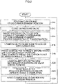
- Fig. 2 is a flow chart illustrating a method of controlling a die cushion device, according to the present invention, and particularly a method of controlling the die cushion device 100 of the first embodiment.
- the die cushion device 100 transitions to a die cushion position control state from a die cushion force control state, and moves (raises) the cushion pad 110 to a preset die cushion standby position.
- Step S10 illustrated in Fig. 2 shows the die cushion position control state where the cushion pad 110 is put on standby (positioned) at the die cushion standby position.
- the die cushion device 100 transitions to the die cushion force control state from the die cushion position control state. Then the controller 160 serving as a pressurization controller first causes the depressure valve 144 to close (step S12). This prevents hydraulic oil from flowing out from the rod side hydraulic chamber 120b of the hydraulic cylinder 120.
- the controller 160 controls the first hydraulic circuit 130 to cause pressure oil to be supplied to the cap side hydraulic chamber 120a of the hydraulic cylinder 120 to pressurize the cap side hydraulic chamber 120a until pressure therein reaches a preset pressure (step S14). Since hydraulic oil is prevented from flowing out from the rod side hydraulic chamber 120b of the hydraulic cylinder 120, the cap side hydraulic chamber 120a of the hydraulic cylinder 120 can be pressurized until pressure therein reaches the preset pressure.
- the preset pressure corresponds to pressure applied to the cap side hydraulic chamber 120a when the hydraulic cylinder 120 generates a preset die cushion force, in the present example.
- the cap side hydraulic chamber 120a of the hydraulic cylinder 120 is pressurized until pressure therein reaches the preset pressure
- the rod side hydraulic chamber 120b of the hydraulic cylinder 120 from which hydraulic oil is prevented from flowing out is also pressurized. While the cushion pad 110 (piston rod 120c) then rises in accordance with an amount of volume compression due to this pressurization in the rod side hydraulic chamber 120b, an amount of rise of the cushion pad 110 in accordance with the amount of volume compression is little, whereby the cushion pad 110 does not greatly rise from a normal die cushion standby position.
- step S16 After that, the slide 14 of the press machine 10 descends to a position slightly above the cushion pad standby position to collide with the cushion pad 110 (step S16).
- the controller 160 controls pressure in the cap side hydraulic chamber 120a of the hydraulic cylinder 120 through the first hydraulic circuit 130 to cause the pressure to be maintained at the preset pressure. Meanwhile, when the cushion pad 110 (piston rod 120c) descends after the slide 14 and the cushion pad 110 collides with each other, pressure (pressure increased previously) in the rod side hydraulic chamber 120b of the hydraulic cylinder 120 is reduced. As a result, the hydraulic cylinder 120 generates die cushion force corresponding to pressure difference between the cap side hydraulic chamber 120a and the rod side hydraulic chamber 120b.
- the hydraulic cylinder 120 When the cushion pad 110 is lowered to the height of a position before rising (die cushion standby position), or when pressure in the rod side hydraulic chamber 120b is reduced to pressure in a state where the cushion pad 110 is at the die cushion standby position (pressure in the tank 148 in the preset example), the hydraulic cylinder 120 generates the preset die cushion force (step S18).
- the controller 160 causes the depressure valve 144 to open (step S20).
- the cushion pad 110 descends, hydraulic oil can flow into the rod side hydraulic chamber 120b of the hydraulic cylinder 120 also through the check valve 142.
- the depressure valve 144 may be controlled to open by the time position control (rising) of the cushion pad 110 starts.
- step S22 When the slide 14 reaches the bottom dead center, forming is completed, and then the slide 14 starts rising (step S22).
- the die cushion device 100 transitions to the die cushion position control state from the die cushion force control state, and raises the cushion pad 110 to the cushion pad standby position (step S24). That is, during the die cushion position control, the controller 160 outputs a control signal for controlling position of the cushion pad 110 to the first hydraulic circuit 130 on the basis of a command value indicating a die cushion position, received from the command device 150, and a die cushion position detected by the die cushion position detector 112.
- the first hydraulic circuit 130 causes hydraulic oil to be supplied to the cap side hydraulic chamber 120a of the hydraulic cylinder 120 in response to the control signal received from the controller 160, thereby raising the cushion pad 110 to the cushion pad standby position.
- the depressure valve 144 opens at step S20, and thus hydraulic oil in the rod side hydraulic chamber 120b is allowed to flow into the tank 148 when the cushion pad 110 (piston rod 120c) rises.
- step S10 to step S24 above are performed in one cycle period of the press machine 10.
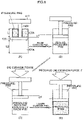
- Fig. 3 illustrates transition of respective states of the hydraulic cylinder 120 from a state where a cushion pad is positioned at a die cushion standby position to a state where the preset die cushion force is generated.
- Portion (A) in Fig. 3 illustrates the hydraulic cylinder 120 in a state where the cushion pad 110 is positioned (put on standby) at the die cushion standby position by the die cushion position control.
- pressure oil is supplied to the cap side hydraulic chamber 120a of the hydraulic cylinder 120 from the state of Portion (A) in Fig. 3 to pressurize the cap side hydraulic chamber 120a until pressure therein reaches a preset pressure PHdc.
- a volume of sealed hydraulic oil includes only a volume of that in the rod side hydraulic chamber 120b of the hydraulic cylinder 120, and a volume of sealed hydraulic oil in piping connected to the rod side hydraulic chamber 120b is neglected for convenience of description.
- weight of the cushion pad 110 and the like is also neglected.
- pressurizing the cap side hydraulic chamber 120a of the hydraulic cylinder 120 to the pressure PHdc causes compression of a volume of hydraulic oil in the rod side hydraulic chamber 120b at the die cushion standby position.
- the piston rod 120c (cushion pad 110) of the hydraulic cylinder 120 is balanced by rising by the amount of a rise x from the die cushion standby position.
- Expression 2 can be replaced with the following expression by using PR1, PR0, L, AR, AH, and the amount of a rise x.
- PR 1 PR 0 + k ⁇ AR ⁇ x / AR ⁇ L
- x PHdc ⁇ AH / AR ⁇ PR 0 ⁇ L / k , thus, it is possible to calculate the amount of a rise x in the case where pressure in the cap side hydraulic chamber 120a is set at PHdc to acquire a required die cushion force F at a position required in design, by using Expression 4.
- AR ⁇ ⁇ 230 / 2 2 ⁇ 180 / 2 2 ) ⁇ 16100 mm 2
- AH ⁇ ⁇ 230 / 2 2 ⁇ 41548 mm 2
- a cylinder inner diameter of the hydraulic cylinder 120 is 230 mm
- a rod diameter of the piston rod 120c is 180 mm
- a cylinder stroke is 400 mm
- a desired die cushion force F is 500 kN
- a cylinder position (a cylinder position corresponding to a cushion pad standby position) at which the die cushion force F is required is 350 mm above a stroke lower limit
- an initial pressure PR0 in the rod side hydraulic chamber 120b is 0.7 MPa
- a volume elastic coefficient k of hydraulic oil is 1000 N/m 2 .
- pressure in the cap side hydraulic chamber 120a pressurized before the die cushion force control starts may be more than pressure when the cushion pad 110 is moved to the die cushion standby position, as well as less than the pressure PHdc.
- pressure in the cap side hydraulic chamber 120a of the hydraulic cylinder 120 cannot be increased to the pressure PHdc (or the amount of a rise x cannot be secured) due to restrictions such as strength of the rod side hydraulic chamber 120b of the hydraulic cylinder 120 and restriction on die structure depending on conditions, high responsivity can be achieved while the amount of a rise x is reduced by controlling pressure in the cap side hydraulic chamber 120a to cause the pressure to be the pressure PHdc at the time when the slide 14 and the cushion pad 110 collide with each other, or at the latest by the time the cushion pad 110 descends by the amount of a rise x, while the pressure PHdc is reduced (the amount of a rise x is reduced).
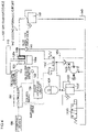
- Fig. 4 is a structural diagram illustrating a second embodiment of the die cushion device according to the present invention.
- a die cushion device 100' of the second embodiment illustrated in Fig. 4 is different from the die cushion device 100 of the first embodiment illustrated in Fig. 1 in that a second hydraulic circuit 140' is used instead of the second hydraulic circuit 140.
- a component in common with the die cushion device 100 of the first embodiment illustrated in Fig. 1 is designated by the same reference numeral to eliminate duplicated description in detail.
- the pilot pressure generating device 143 generates pilot pressure for controlling opening/closing of the pilot drive type check valve 141, and includes an accumulator 143A for accumulating hydraulic oil under the pilot pressure, a hydraulic pump 143B for generating the pilot pressure, a solenoid changeover valve (3-port, 2-position solenoid valve) 143C for pilot operation, and the like.
- the hydraulic pump 143B is driven by an electric motor 143D to supply pressure oil to the accumulator 143A through a check valve 143E.
- the hydraulic pump 143B is only driven when pressure of hydraulic oil accumulated in the accumulator 143A decreases to below a predetermined pilot pressure.
- Reference numeral 143F designates a relief valve that is used to prevent a hydraulic device from breaking by allowing pressure oil to flow out when the pilot pressure becomes abnormal pressure.
- Reference numeral 143G designates a relief valve that is used when the pilot pressure is reduced, and that is normally closed.
- the solenoid changeover valve 143C is controlled (direction switching control) by a switching signal received from the controller 160, and is switched from a position illustrated in Fig. 4 to apply the pilot pressure to the pilot drive type check valve 141, when a solenoid of the solenoid changeover valve 143C is excited by the switching signal.
- This causes the pilot drive type check valve 141 to open to enable hydraulic oil in the rod side hydraulic chamber 120b of the hydraulic cylinder 120 to flow out from the rod side hydraulic chamber 120b to the tank 148 through the pilot drive type check valve 141.
- the solenoid changeover valve 143C is switched to a position illustrated in Fig. 4 to reduce the pilot pressure applied to the pilot drive type check valve 141, and then the pilot drive type check valve 141 is closed. This prevents hydraulic oil from flowing out from the rod side hydraulic chamber 120b of the hydraulic cylinder 120.
- the second hydraulic circuit 140' configured as above is different in configuration from the second hydraulic circuit 140 illustrated in Fig. 1 , as with the second hydraulic circuit 140, the second hydraulic circuit 140' can prevent hydraulic oil from flowing out from the rod side hydraulic chamber 120b of the hydraulic cylinder 120, or enables hydraulic oil to flow out from the rod side hydraulic chamber 120b of the hydraulic cylinder 120, by using a switching signal from the controller 160.
- Fig. 5 is a flow chart illustrating a method of controlling the die cushion device 100' of the second embodiment above. A portion in common with the flow chart illustrated in Fig. 2 is designated by a common step number to eliminate duplicated description in detail.
- the flow chart illustrated in Fig. 5 is different from the flow chart illustrated in Fig. 2 in that processes at step S120 and step S200 are performed instead of those at step S12 and step S20.
- the pilot drive type check valve 141 is closed to prevent hydraulic oil from flowing out from the rod side hydraulic chamber 120b of the hydraulic cylinder 120, thereby enabling the cap side hydraulic chamber 120a to be pressurized, at step S120.
- the pilot drive type check valve 141 is opened at step S200.
- the cushion pad 110 descends, hydraulic oil can flow into the rod side hydraulic chamber 120b of the hydraulic cylinder 120 through the pilot drive type check valve 141 even if pilot pressure is applied to the pilot drive type check valve 141, and thus the pilot drive type check valve 141 may be controlled to be opened by the time position control (rising) of the cushion pad 110 starts.
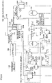
- Fig. 6 is a structural diagram corresponding to the die cushion device 100' of the second embodiment illustrated in Fig. 4 , and is a structural diagram including particularly a first hydraulic circuit 130-1 of the first embodiment, corresponding to the first hydraulic circuit 130 illustrated in Fig. 1 .
- the die cushion device 100' illustrated in Fig. 6 includes an accumulator 149 under a gas pressure of a low pressure (e.g. 0.7 MPa), serving as a tank, instead of the tank 148 illustrated in Fig. 4 , the accumulator 149 being connected to a low pressure line.
- a low pressure e.g. 0.7 MPa
- the first hydraulic circuit 130-1 of the first embodiment illustrated in Fig. 6 includes: a hydraulic pump/motor (fluid-pressure pump/motor) 130A; a servo motor (electric motor) 130B connected to a rotating shaft of the hydraulic pump/motor 130A; an angular speed detector 130C that detects angular speed (servo motor angular speed ⁇ ) of a drive shaft of the servo motor 130B; a pilot drive type check valve 130D; a solenoid changeover valve 130E; and a relief valve 130F serving as a safety valve.
- One port (discharge port) of the hydraulic pump/motor 130A is connected to the cap side hydraulic chamber 120a of the hydraulic cylinder 120 through the pilot drive type check valve 130D, and the other port is connected to the low pressure line to which the accumulator 149 is connected.
- the die cushion pressure detector 122 detects pressure applied to the cap side hydraulic chamber 120a of the hydraulic cylinder 120, and the angular speed detector 130C detects angular speed of the drive shaft of the servo motor 130B.
- controlling the die cushion force means controlling the pressure in the cap side hydraulic chamber 120a of the hydraulic cylinder 120.
- the die cushion pressure causes the hydraulic pump/motor 130A to serve as a hydraulic motor to rotate the servo motor 130B when rotating shaft torque generated in the hydraulic pump/motor 130A becomes equal to driving torque of the servo motor 130B, thereby preventing the die cushion pressure from rising.
- the die cushion force is determined in accordance with drive torque of the servo motor 130B.
- the command device 150 outputs a command value corresponding to a required die cushion force.
- the cushion pad 110 is controlled in position, and a command value indicating the preset pressure PHdc is outputted when the cushion pad 110 reaches the die cushion standby position.
- the controller 160 When the cushion pad 110 reaches the die cushion standby position and control is switched from the die cushion position control state to the die cushion force control state, the controller 160 outputs a torque command calculated by using a command value corresponding to die cushion force, a die cushion pressure detection signal, and a servo motor angular speed signal to the servo motor 130B through an amplifier (not illustrated), thereby performing the die cushion force control.
- the controller 160 starts torque control of the servo motor 130B, and controls (switches) the solenoid changeover valve 130E to open the pilot drive type check valve 130D.
- a direction of torque output of the servo motor 130B and that of generation speed are opposite to each other. That is, pressure oil flows into the hydraulic pump/motor 130A from the cap side hydraulic chamber 120a of the hydraulic cylinder 120 through the pilot drive type check valve 130D by using power received by the cushion pad 110 from the slide 14 to cause the hydraulic pump/motor 130A to serve as a hydraulic motor. Since the servo motor 130B is driven by the hydraulic pump/motor 130A to serve as a generator, it is preferable to use electric power generated by the servo motor 130B as regenerative power.
- the command device 150 causes knock-out operation for a product to be performed after the slide 14 reaches the bottom dead center and the die cushion force control is finished, and outputs a command value (position command value) of controlling position of the cushion pad 110 to cause the cushion pad 110 to move (rise) to the die cushion standby position.
- the controller 160 controls the servo motor 130B on the basis of a position command value received from the command device 150 and a detection signal of die cushion position detected by the die cushion position detector 112 to cause the hydraulic pump/motor 130A to supply pressure oil to the cap side hydraulic chamber 120a of the hydraulic cylinder 120.
- controlling a position in a stretching direction of the piston rod 120c of the hydraulic cylinder 120 enables control of a position (die cushion position) in a lifting direction of the cushion pad 110.
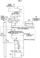
- Fig. 7 is a structural diagram corresponding to the die cushion device 100' of the second embodiment illustrated in Fig. 4 , and is a structural diagram including particularly the first hydraulic circuit 130-2 of the second embodiment.
- the first hydraulic circuit 130-2 of the second embodiment illustrated in Fig. 6 includes a 4-port, 2-position proportion flow control valve (hereinafter referred to as simply a "proportion flow control valve") 131, a solenoid changeover valve 132, a check valve 133, a pressure oil supply source with an accumulator 143A (including the hydraulic pump 143B, the electric motor 143D, and the relief valve 143F), and the like.
- the die cushion pressure detector 122 for detecting pressure in the cap side hydraulic chamber 120a as well as an A port of the proportion flow control valve 131 is connected to a flow channel connected to the cap side hydraulic chamber 120a of the hydraulic cylinder 120, and a flow channel connected to the rod side hydraulic chamber 120b of the hydraulic cylinder 120 is connected to a B port of the proportion flow control valve 131 through the pilot drive type check valve 141 as well as to the tank 148 through the check valve 133.
- the accumulator 143A is set under high pressure gas pressure to hold pressure oil under high pressure.
- the pressure oil under high pressure is supplied to the cap side hydraulic chamber 120a of the hydraulic cylinder 120 through the solenoid changeover valve 132 and the proportion flow control valve 131 to raise the cushion pad 110, and is supplied as pilot pressure of the pilot drive type check valve 141 through the solenoid changeover valve 143C, at the time of the die cushion position control.
- the slide 14 of the press machine is provided with a slide position detector 32 and a slide speed detector 33.
- Respective detection signals of the slide position detector 32, the slide speed detector 33, the die cushion position detector 112, and the die cushion pressure detector 122 are received by a controller 160'.
- the controller 160' is configured to receive a command value indicating a die cushion force or a die cushion pressure corresponding to the die cushion force, and a command value indicating a position (die cushion position) such as a knock-out position and a die cushion standby position, from the command device 150.
- the controller 160' is configured to perform the die cushion force control and the die cushion position control, and outputs not only a control signal for controlling the proportion flow control valve 131, but also a switching signal for switching the solenoid changeover valves 132 and 143C, on the basis of the command values above and the detection signals above.
- controlling the die cushion force means controlling the pressure in the cap side hydraulic chamber 120a of the hydraulic cylinder 120.
- Pressure P in the cap side hydraulic chamber 120a of the hydraulic cylinder 120 can be expressed by the following expression.
- P K / V ⁇ q ⁇ l / s , where each symbol means the following:
- an outflow Q from the cap side hydraulic chamber 120a through the proportion flow control valve 131 can be expressed by the following expression using a valve coefficient Kv proportional to an opening of the proportion flow control valve 131, and the pressure P in the cap side hydraulic chamber 120a.
- Q Kv ⁇ P
- the valve coefficient Kv is proportional to the spool displacement x of the proportion flow control valve 131 as expressed by Expression 8, and the proportion flow control valve 131 has a spool position that varies in proportion to a proportion flow control valve command. Thus, if pressure difference is constant, a flow rate of hydraulic oil is determined in proportion to the proportion flow control valve command.
- the valve coefficient Kv can be acquired by substituting command pressure of die cushion indicated as Pr, and a flow rate acquired by slide speed indicated as Qs, for P and Q in Expression 9, respectively. If the proportion flow control valve 131 is controlled to have a spool displacement (opening) corresponding to the valve coefficient Kv, the pressure P in the cap side hydraulic chamber 120a can be controlled to be the command pressure Pr.
- the outflow Q through the proportion flow control valve 131 is less than the inflow Qs into the cap side hydraulic chamber 120a (Q ⁇ Qs).
- the command device 150 outputs a command value corresponding to a required die cushion force.
- the cushion pad 110 is controlled in position, and a command value indicating the preset pressure PHdc is outputted when the cushion pad 110 reaches the die cushion standby position. While it is preferable that the pressure oil supply source with the accumulator 143A supplies pressure oil under the pressure PHdc, pressure oil under pressure less than the pressure PHdc may be supplied.
- the controller 160' When the cushion pad 110 reaches the die cushion standby position and control is switched from the die cushion position control state to the die cushion force control state, the controller 160' outputs a switching signal for demagnetizing a solenoid of the solenoid changeover valve 143C to cause no pilot pressure to be applied to the pilot drive type check valve 141, thereby closing the pilot drive type check valve 141.
- controller 160' outputs a control signal to each of the solenoid changeover valve 132 and the proportion flow control valve 131 to cause the pressure oil supply source with the accumulator 143A to supply pressure oil under high pressure to the cap side hydraulic chamber 120a of the hydraulic cylinder 120 through the solenoid changeover valve 132 and the proportion flow control valve 131, thereby pressurizing the cap side hydraulic chamber 120a to cause pressure therein to be the same as the pressure in the accumulator 143A.
- the controller 160' While the slide 14 descends and the slide 14 reaches the bottom dead center after colliding with the cushion pad 110 (during forming), the controller 160' outputs not only a switching signal for closing the solenoid changeover valve 132 to close the P port of the proportion flow control valve 131, but also a pressure command corresponding to a preset die cushion force and a control signal for the proportion flow control valve, calculated on the basis of slide speed, to the proportion flow control valve 131 to cause the proportion flow control valve 131 to have an appropriate opening. Accordingly, a flow rate (an outflow from the cap side hydraulic chamber 120a of the hydraulic cylinder 120) through the proportion flow control valve 131 is controlled, whereby pressure in the cap side hydraulic chamber 120a is controlled to be pressure allowing required die cushion force to be generated.
- the command device 150 causes knock-out operation for a product to be performed after the slide 14 reaches the bottom dead center and the die cushion force control is finished, and outputs a command value (position command value) of controlling position of the cushion pad 110 to cause the cushion pad 110 to move (rise) to the die cushion standby position.
- the controller 160' In the case of the die cushion position control state, the controller 160' outputs a switching signal for opening the solenoid changeover valve 132 to open the P port of the proportion flow control valve 131, and causes a solenoid of the solenoid changeover valve 143C to be excited to apply pilot pressure to the pilot drive type check valve 141 through the solenoid changeover valve 143C to open the pilot drive type check valve 141, thereby enabling hydraulic oil to flow out from the rod side hydraulic chamber 120b. Subsequently, the controller 160' controls an opening of the proportion flow control valve 131 on the basis of a position command value from the command device 150 and a die cushion position signal from the die cushion position detector 112 to cause the cushion pad 110 to move to the die cushion standby position.
- the die cushion device according to the present invention and a conventional die cushion device will be compared in a configuration and an operation effect.
- the conventional die cushion device is controlled to cause a cushion pad to stop at a position above a cushion pad standby position by a predetermined amount before die cushion force control starts, and then a slide collides with the cushion pad and the cushion pad is pressed down to a height before rising to generate die cushion force corresponding to a setting pressure.
- hydraulic oil in a rod side hydraulic chamber of a hydraulic cylinder can freely flow in and out.
- a cap side hydraulic chamber and the rod side hydraulic chamber of the hydraulic cylinder are not (cannot be) pressurized to high pressure.
- Fig. 8 illustrates transition of respective states of a hydraulic cylinder 120 of the conventional die cushion device from a state where a cushion pad 110 is positioned at a die cushion standby position to a state where the preset die cushion force is generated.
- Portion (A) in Fig. 8 illustrates the hydraulic cylinder 120 in a state where the cushion pad 110 is positioned (put on standby) at the die cushion standby position by the die cushion position control.
- a dimension (length) of the rod side hydraulic chamber 120b in a stretching direction is indicated as L
- a dimension (length) of a cap side hydraulic chamber 120a in the stretching direction is indicated as L2.
- position control of the cushion pad is further performed in the state of Portion (A) in Fig. 8 to raise the cushion pad 110 (piston rod 120c) by a predetermined amount of a rise x' from the cushion pad standby position.
- pressure in the cap side hydraulic chamber 120a of the hydraulic cylinder 120 is to be pressure PH0
- pressure in the rod side hydraulic chamber 120b is to be pressure PR0.
- volume of sealed hydraulic oil includes only volume of that in the cap side hydraulic chamber 120a of the hydraulic cylinder 120, and volume of sealed hydraulic oil in piping is neglected.
- volume in the rod side hydraulic chamber 120b is sufficiently large, weight of the cushion pad 110 and the like is neglected.
- the sealed pressure PH0 in the cap side hydraulic chamber 120a of the hydraulic cylinder 120 can be expressed by the following expression, where pressure in the rod side hydraulic chamber 120b is indicated as the pressure PR0.
- PH 0 PR 0 ⁇ AR / AH , where
- volume of sealed hydraulic oil includes only volume of that in the rod side hydraulic chamber 120b of the hydraulic cylinder 120, and volume of sealed hydraulic oil in piping connected to the rod side hydraulic chamber 120b is neglected for convenience of description. In addition, weight of the cushion pad 110 and the like is also neglected.
- the cushion pad 110 When the cushion pad 110 is pressed by the amount of a rise x' as illustrated in Portion (D) in Fig. 8 (the cushion pad 110 reaches the die cushion standby position), pressure in the cap side hydraulic chamber 120a of the hydraulic cylinder 120 is caused to be a predetermined pressure PHdc, and then the hydraulic cylinder 120 generates required die cushion force F.
- the amount of a rise x' of the cushion pad 110 is determined to cause the pressure PH0 before change in volume to be the pressure PHdc due to change in volume in the cap side hydraulic chamber 120a when the cushion pad 110 is pressed by the amount of a rise x'.
- Expression 11 can be replaced with the following expression by using PHdc, PH0, L2, AR, AH, and the amount of a rise x'.
- PHdc PH 0 + k ⁇ AH ⁇ x ′ / AH ⁇ L 2
- x ′ PHdc ⁇ PH 0 ⁇ L 2 / k
- PHdc 500000 + 0.7 ⁇ 16100 / 41548 ⁇ 12.3 MPa
- the conventional die cushion device (without preventing hydraulic oil in the rod side hydraulic chamber 120b of the hydraulic cylinder 120 from flowing out) needs the amount of a rise x' (about 4.21 mm) by which the cushion pad rises to acquire die cushion force required at the die cushion standby position, the amount of a rise x' being almost three times the amount of a rise x.
- the hydraulic cylinder may be provided not only at one place in the cushion pad, as with the present embodiment, but also at two places of the front and rear of the cushion pad, or at four places of the front and rear, and the right and left, of the cushion pad, for example.
- a hydraulic circuit and a method of controlling it, causing a hydraulic cylinder to generate required die cushion force are not limited to those of the present embodiment, and various types are available.
- the die cushion device in which oil is used for operation fluid is described, besides this, water or another liquid may be used. That is, while the present embodiment is described by using the form in which a hydraulic cylinder and a hydraulic circuit are used, besides this, a fluid-pressure cylinder and a fluid-pressure circuit in which water or another liquid is used can be obviously used for the present invention.
Landscapes
- Engineering & Computer Science (AREA)
- Mechanical Engineering (AREA)
- Shaping Metal By Deep-Drawing, Or The Like (AREA)
- Presses And Accessory Devices Thereof (AREA)
Claims (14)
- Ziehkissen-Vorrichtung (100), die umfasst:einen Fluiddruck-Zylinder (120), der so ausgeführt ist, dass er eine Kissenplatte (110) trägt und Ziehkissenkraft erzeugt, wenn sich ein Stößel einer Pressmaschine absenkt;einen ersten Fluiddruck-Kreis (130), der so ausgeführt ist, dass er einer deckelseitigen Fluiddruck-Kammer (120a) des Fluiddruck-Zylinders (120) Betriebsfluid zuleitet oder das Betriebsfluid aus der deckelseitigen Fluiddruck-Kammer (120a) ableitet; undeinen zweiten Fluiddruck-Kreis (140), der so ausgeführt ist, dass er zulässt, dass das Betriebsfluid daran gehindert wird, aus einer stangenseitigen Fluiddruck-Kammer (120b) des Fluiddruck-Zylinders (120) auszuströmen, oder so ausgeführt ist, dass er zulässt,dass das Betriebsfluid in die stangenseitige Fluiddruck-Kammer (120b) einströmt; sowieeine Druckbeaufschlagungs-Steuerungseinrichtung (160), die so ausgeführt ist, dass sie den zweiten Fluiddruck-Kreis (140), bevor Steuerung von Ziehkissenkraft beginnt, so steuert, dass veranlasst wird, dass das Betriebsfluid daran gehindert wird, aus der stangenseitigen Fluiddruck-Kammer (120b) des Fluiddruck-Zylinders (120) auszuströmen, und den ersten Fluiddruck-Kreis (130) so steuert, das veranlasst wird, dass der deckelseitigen Fluiddruck-Kammer (120a) des Fluiddruck-Zylinders (120) Druckfluid zugeleitet wird, während das Betriebsfluid daran gehindert wird, aus der stangenseitigen Fluiddruck-Kammer (120b) auszuströmen, um die deckelseitige Fluiddruck-Kammer (120a) mit Druck zu beaufschlagen.
- Ziehkissen-Vorrichtung (100) nach Anspruch 1, wobeider zweite Fluiddruck-Kreis ein Rückschlagventil (142), das so ausgeführt ist, dass es verhindert, dass das Betriebsfluid aus der stangenseitigen Fluiddruck-Kammer des Fluiddruck-Zylinders ausströmt, sowie ein Druckreduzierventil enthält, das parallel zu dem Rückschlagventil vorhanden ist, unddie Druckbeaufschlagungs-Steuerungseinrichtung so ausgeführt ist, dass sie das Druckreduzierventil steuert, bevor die Steuerung von Ziehkissenkraft beginnt, um Schließen des Druckreduzierventils zu veranlassen, und verhindert, dass das Betriebsfluid aus der stangenseitigen Fluiddruck-Kammer des Fluiddruck-Zylinders ausströmt.
- Ziehkissen-Vorrichtung (100) nach Anspruch 1, wobeider zweite Fluiddruck-Kreis ein Vorsteuer-Rückschlagventil (141) enthält, das so ausgeführt ist, dass es verhindert, dass das Betriebsfluid aus der stangenseitigen Fluiddruck-Kammer des Fluiddruck-Zylinders ausströmt, unddie Druckbeaufschlagungs-Steuerungseinrichtung so ausgeführt ist, dass sie Vorsteuerdruck steuert, bevor die Steuerung von Ziehkissenkraft beginnt, um Schließen des Vorsteuer-Rückschlagventils zu veranlassen, und verhindert, dass das Betriebsfluid aus der stangenseitigen Fluiddruck-Kammer des Fluiddruck-Zylinders ausströmt.
- Ziehkissen-Vorrichtung (100) nach einem der Ansprüche 1 bis 3, die des Weiteren umfasst:eine Ziehkissenpositions-Steuerungseinrichtung (160), die so ausgeführt ist, dass sie zulässt, dass das Betriebsfluid der deckelseitigen Fluiddruck-Kammer des Fluiddruck-Zylinders zugeleitet wird, um die Kissenplatte an eine vorgegebene Ziehkissen-Bereitschaftsposition anzuheben, nachdem die Steuerung von Ziehkissenkraft abgeschlossen ist,wobei die Druckbeaufschlagungs-Steuerungseinrichtung so ausgeführt ist, dass sie, wenn die Kissenplatte durch die Ziehkissenpositions-Steuerungseinrichtung an die Ziehkissen-Bereitschaftsposition bewegt wird, zulässt, dass das Druckfluid der deckelseitigen Fluiddruck-Kammer des Fluiddruck-Zylinders zugeleitet wird, indem sie den ersten Fluiddruck-Kreis steuert, während das Betriebsfluid daran gehindert wird, aus der stangenseitigen Fluiddruck-Kammer des Fluiddruck-Zylinders auszuströmen, indem der zweite Fluiddruck-Kreis gesteuert wird.
- Ziehkissen-Vorrichtung (100) nach einem der Ansprüche 1 bis 4, wobei Druck in der deckelseitigen Fluiddruck-Kammer des Fluiddruck-Zylinders, der durch die Druckbeaufschlagungs-Steuerungseinrichtung mit Druck beaufschlagt wird, Druck gleich ist, bei dem der Fluiddruck-Zylinder eine voreingestellte Ziehkissenkraft erzeugt.
- Ziehkissen-Vorrichtung (100) nach Anspruch 4, wobei Druck in der deckelseitigen Fluiddruck-Kammer des Fluiddruck-Zylinders, der durch die Druckbeaufschlagungs-Steuerungseinrichtung mit Druck beaufschlagt wird, höher ist als Druck, bei dem die Kissenplatte an die Ziehkissen-Bereitschaftsposition bewegt wird, und niedriger als Druck, bei dem der Fluiddruck-Zylinder die voreingestellte Ziehkissenkraft erzeugt.
- Ziehkissen-Vorrichtung (100) nach einem der Ansprüche 1 bis 6, die des Weiteren umfasst:einen Druckdetektor (122), der so ausgeführt ist, dass er Druck in der deckelseitigen Fluiddruck-Kammer des Fluiddruck-Zylinders erfasst;eine Fluiddruck-Pumpe/einen Fluiddruck-Motor (130A) mit einer Ableitöffnung, die über eine Rohrleitung mit der deckelseitigen Fluiddruck-Kammer des Fluiddruck-Zylinders verbunden ist;einen Elektromotor (130B), der mit einer rotierenden Welle der Fluiddruck-Pumpe/des Fluiddruck-Motors verbunden ist;eine Ziehkissendruck-Befehlsvorrichtung (150), die so ausgeführt ist, dass sie einen voreingestellten Ziehkissendruck-Befehl ausgibt; undeine Ziehkissenkraft-Steuerungseinrichtung (160), die so ausgeführt ist, dass sie Drehmoment des Elektromotors auf Basis des Ziehkissendruck-Befehls und des von dem Druckdetektor erfassten Drucks steuert, um zu veranlassen, dass Ziehkissendruck einem Druck gleich ist, der dem Ziehkissendruck-Befehl entspricht.
- Ziehkissen-Vorrichtung (100) nach Anspruch 7, wobei die Druckbeaufschlagungs-Steuerungseinrichtung so ausgeführt ist, dass sie, bevor Steuerung von Ziehkissenkraft beginnt, Drehmoment des Elektromotors steuert, um Fluiddruck zu steuern, der der deckelseitigen Fluiddruck-Kammer des Fluiddruck-Zylinders zugeleitet wird.
- Ziehkissen-Vorrichtung (100) nach einem der Ansprüche 1 bis 6, die des Weiteren umfasst:ein Proportional-Stromregelventil (131), das in einer mit der deckelseitigen Fluiddruck-Kammer des Fluiddruck-Zylinders verbundenen Rohrleitung vorhanden ist; sowieeine Ziehkissenkraft-Steuerungseinrichtung (160), die so ausgeführt ist, dass sie Öffnen des Proportional-Stromregelventils steuert, um zu veranlassen, dass eine Durchflussrate des aus der deckelseitigen Fluiddruck-Kammer des Fluiddruck-Zylinders abgeleiteten Betriebsfluids gesteuert wird, um den Druck in der deckelseitigen Fluiddruck-Kammer des Fluiddruck-Zylinders zu steuern.
- Verfahren zum Steuern einer Ziehkissen-Vorrichtung (100), die einen Fluiddruck-Zylinder (120), der so ausgeführt ist, dass er eine Kissenplatte (110) trägt und Ziehkissenkraft erzeugt, wenn sich ein Stößel einer Pressmaschine absenkt, einen ersten Fluiddruck-Kreis (130), der so ausgeführt ist, dass er einer deckelseitigen Fluiddruck-Kammer (120a) des Fluiddruck-Zylinders (120) Betriebsfluid zuleitet oder das Betriebsfluid aus der deckelseitigen Fluiddruck-Kammer (120a) ableitet, sowie einen zweiten Fluiddruck-Kreis (140) enthält, der so ausgeführt ist, dass er zulässt, dass das Betriebsfluid daran gehindert wird, aus einer stangenseitigen Fluiddruck-Kammer (120b) des Fluiddruck-Zylinders (120) auszuströmen, oder so ausgeführt ist, dass er zulässt, dass das Betriebsfluid in die stangenseitige Fluiddruck-Kammer (120b) einströmt, wobei das Verfahren die folgenden Schritte umfasst:Verhindern, dass das Betriebsfluid aus der stangenseitigen Fluiddruck-Kammer (120b) des Fluiddruck-Zylinders (120) ausströmt, mittels Steuern des zweiten Fluiddruck-Kreises (140), bevor die Steuerung von Ziehkissenkraft beginnt; undBeaufschlagen der deckelseitigen Fluiddruck-Kammer (120a) des Fluiddruck-Zylinders (120) mit Druck durch Zuleiten von Druckfluid zu der deckelseitigen Fluiddruck-Kammer (120a) des Fluiddruck-Zylinders (120) mittels Steuern des ersten Fluiddruck-Kreises (130), während das Betriebsfluid daran gehindert wird, aus der stangenseitigen Fluiddruck-Kammer (120b) auszuströmen, bevor die Steuerung von Ziehkissenkraft beginnt.
- Verfahren zum Steuern der Ziehkissen-Vorrichtung (100) nach Anspruch 10, das des Weiteren den folgenden Schritt umfasst:Zuleiten des Betriebsfluids zu der deckelseitigen Fluiddruck-Kammer des Fluiddruck-Zylinders, nachdem die Steuerung von Ziehkissenkraft abgeschlossen ist, um zu veranlassen, dass die Kissenplatte an eine vorgegebene Ziehkissen-Bereitschaftsposition ansteigt,wobei in dem Schritt, in dem verhindert wird, dass das Betriebsfluid ausströmt, der zweite Fluiddruck-Kreis gesteuert wird, um zu verhindern, dass das Betriebsfluid aus der stangenseitigen Fluiddruck-Kammer des Fluiddruck-Zylinders ausströmt, wenn die Kissenplatte an die Ziehkissen-Bereitschaftsposition bewegt wird.
- Verfahren zum Steuern der Ziehkissen-Vorrichtung (100) nach Anspruch 10 oder 11, wobei Druck in der deckelseitigen Fluiddruck-Kammer des Fluiddruck-Zylinders, der in dem Druckbeaufschlagungs-Schritt mit Druck beaufschlagt wird, dem Druck gleich ist, bei dem der Fluiddruck-Zylinder eine voreingestellte Ziehkissenkraft erzeugt.
- Verfahren zum Steuern der Ziehkissen-Vorrichtung (100) nach Anspruch 11, wobei Druck in der deckelseitigen Fluiddruck-Kammer des Fluiddruck-Zylinders, der in dem Druckbeaufschlagungs-Schritt mit Druck beaufschlagt wird, höher ist als Druck, bei dem die Kissenplatte an die Ziehkissen-Bereitschaftsposition bewegt wird, und niedriger als Druck, bei dem der Fluiddruck-Zylinder die voreingestellte Ziehkissenkraft erzeugt.
- Verfahren zum Steuern der Ziehkissen-Vorrichtung (100) nach Anspruch 10 oder 11, wobeidie Ziehkissen-Vorrichtung des Weiteren eine Ziehkissenpositions-Steuerungseinrichtung (160) enthält, die so ausgeführt ist, dass sie zulässt, dass das Betriebsfluid der deckelseitigen Fluiddruck-Kammer des Fluiddruck-Zylinders zugeleitet wird, um die Kissenplatte an eine vorgegebene Ziehkissen-Bereitschaftsposition anzuheben, nachdem die Steuerung von Ziehkissenkraft abgeschlossen ist, unddas Verfahren den Schritt des Steuerns des zweiten Fluiddruck-Kreises bei Pressformen, das mittels Absenken des Stößels durchgeführt wird, und bei Positionssteuerung der Kissenplatte einschließt, durch die zugelassen wird, dass das Betriebsfluid bei dem Pressformen in die stangenseitige Fluiddruck-Kammer des Fluiddruck-Zylinders einströmt, und zugelassen wird, dass das Betriebsfluid bei der Positionssteuerung aus der stangenseitigen Fluiddruck-Kammer des Fluiddruck-Zylinders ausströmt.
Applications Claiming Priority (1)
| Application Number | Priority Date | Filing Date | Title |
|---|---|---|---|
| JP2015252167A JP6153270B2 (ja) | 2015-12-24 | 2015-12-24 | ダイクッション装置及びダイクッション装置の制御方法 |
Publications (2)
| Publication Number | Publication Date |
|---|---|
| EP3184187A1 EP3184187A1 (de) | 2017-06-28 |
| EP3184187B1 true EP3184187B1 (de) | 2022-05-25 |
Family
ID=57629340
Family Applications (1)
| Application Number | Title | Priority Date | Filing Date |
|---|---|---|---|
| EP16205284.9A Active EP3184187B1 (de) | 2015-12-24 | 2016-12-20 | Ziehkissenvorrichtung und verfahren zur steuerung der ziehkissenvorrichtung |
Country Status (4)
| Country | Link |
|---|---|
| US (1) | US10710138B2 (de) |
| EP (1) | EP3184187B1 (de) |
| JP (1) | JP6153270B2 (de) |
| CN (1) | CN106925653B (de) |
Families Citing this family (12)
| Publication number | Priority date | Publication date | Assignee | Title |
|---|---|---|---|---|
| WO2018075347A1 (en) * | 2016-10-18 | 2018-04-26 | Barnes Group Inc. | Variable pulsating, gap control, auto-learning press cushion device |
| JP6527543B2 (ja) * | 2017-03-28 | 2019-06-05 | Jfeスチール株式会社 | プレス成形装置及びプレス成形品の製造方法 |
| JP6500927B2 (ja) * | 2017-03-28 | 2019-04-17 | Jfeスチール株式会社 | プレス成形装置及びプレス成形品の製造方法 |
| JP6527544B2 (ja) * | 2017-03-28 | 2019-06-05 | Jfeスチール株式会社 | プレス成形装置及びプレス成形品の製造方法 |
| JP6646637B2 (ja) * | 2017-09-12 | 2020-02-14 | アイダエンジニアリング株式会社 | しわ発生検出装置、ダイクッション装置及び金型保護装置、並びにしわ発生検出方法、ダイクッション力自動設定方法及び金型保護方法 |
| CN109570311B (zh) * | 2019-01-12 | 2024-06-07 | 盐城市富源引擎科技有限公司 | 一种汽车座椅滑轨用冲压模具 |
| CN111505967B (zh) * | 2020-05-06 | 2025-01-14 | 中核(天津)科技发展有限公司 | 半自动装配及检测装置控制电路 |
| JP7381438B2 (ja) | 2020-12-18 | 2023-11-15 | アイダエンジニアリング株式会社 | ダイクッション装置 |
| JP7419224B2 (ja) | 2020-12-25 | 2024-01-22 | アイダエンジニアリング株式会社 | ダイクッション装置 |
| KR102501156B1 (ko) * | 2022-03-17 | 2023-02-17 | 갑산메탈 주식회사 | 플랜지관 제조장치 및 제조방법 |
| JP7774829B1 (ja) * | 2025-04-23 | 2025-11-25 | 茂 森 | ロールプレス機用ロール圧下装置及びロール圧下方法 |
| CN121156132B (zh) * | 2025-11-24 | 2026-02-24 | 山东大瀚环境科技有限公司 | 一种带有纠偏功能的空冷器冲压装置 |
Citations (1)
| Publication number | Priority date | Publication date | Assignee | Title |
|---|---|---|---|---|
| JPH0829365B2 (ja) * | 1987-08-28 | 1996-03-27 | 石川島播磨重工業株式会社 | プレス機械のダイクッション装置 |
Family Cites Families (11)
| Publication number | Priority date | Publication date | Assignee | Title |
|---|---|---|---|---|
| JPH0790400B2 (ja) * | 1989-10-18 | 1995-10-04 | アイダエンジニアリング株式会社 | プレスのダイクッション装置 |
| JP3308463B2 (ja) | 1996-12-27 | 2002-07-29 | アイダエンジニアリング株式会社 | ダイクッションの制御方法 |
| DE10336279A1 (de) * | 2003-08-07 | 2005-03-03 | Bosch Rexroth Ag | Einrichtung zur Steuerung des Ziehvorgangs bei einer Transferpresse |
| JP4233514B2 (ja) | 2004-11-04 | 2009-03-04 | ファナック株式会社 | ダイクッション機構並びにその制御装置及び制御方法 |
| JP4357405B2 (ja) | 2004-11-05 | 2009-11-04 | ファナック株式会社 | サーボモータの制御装置 |
| JP4756678B2 (ja) * | 2004-11-16 | 2011-08-24 | アイダエンジニアリング株式会社 | プレス機械のダイクッション装置 |
| JP4820564B2 (ja) | 2005-03-16 | 2011-11-24 | 株式会社小松製作所 | ダイクッション制御装置 |
| JP4576639B2 (ja) | 2005-05-16 | 2010-11-10 | アイダエンジニアリング株式会社 | プレス機械のダイクッション装置 |
| JP2010058710A (ja) * | 2008-09-04 | 2010-03-18 | Toyota Motor Corp | サスペンション装置およびビスカスカップリング |
| JP5440838B2 (ja) | 2009-04-02 | 2014-03-12 | 株式会社Ihi | 油圧ダイクッション装置とその位置制御方法 |
| DE102010019324B4 (de) | 2010-05-03 | 2015-05-07 | Schuler Pressen Gmbh | Hydraulisches Ziehkissen |
-
2015
- 2015-12-24 JP JP2015252167A patent/JP6153270B2/ja active Active
-
2016
- 2016-12-20 EP EP16205284.9A patent/EP3184187B1/de active Active
- 2016-12-20 US US15/384,478 patent/US10710138B2/en active Active
- 2016-12-23 CN CN201611205860.4A patent/CN106925653B/zh active Active
Patent Citations (1)
| Publication number | Priority date | Publication date | Assignee | Title |
|---|---|---|---|---|
| JPH0829365B2 (ja) * | 1987-08-28 | 1996-03-27 | 石川島播磨重工業株式会社 | プレス機械のダイクッション装置 |
Also Published As
| Publication number | Publication date |
|---|---|
| JP6153270B2 (ja) | 2017-06-28 |
| CN106925653B (zh) | 2021-04-20 |
| JP2017113786A (ja) | 2017-06-29 |
| CN106925653A (zh) | 2017-07-07 |
| EP3184187A1 (de) | 2017-06-28 |
| US20170182539A1 (en) | 2017-06-29 |
| US10710138B2 (en) | 2020-07-14 |
Similar Documents
| Publication | Publication Date | Title |
|---|---|---|
| EP3184187B1 (de) | Ziehkissenvorrichtung und verfahren zur steuerung der ziehkissenvorrichtung | |
| US10363594B2 (en) | Die cushion apparatus of press machine and die cushion controlling method | |
| EP3115119B1 (de) | Ziehkissen- und stösselkissenvorrichtung und verfahren zur steuerung derselben | |
| US8037735B2 (en) | Die cushion apparatus of press machine | |
| CN101060944B (zh) | 压力机械的模具缓冲装置 | |
| KR101530608B1 (ko) | 프레스 장치용 다이쿠션 시스템 | |
| US10603709B2 (en) | Die cushion device | |
| US20180117656A1 (en) | Die cushion device of press machine | |
| JP2015123464A (ja) | ダイクッション力制御方法及びダイクッション装置 | |
| DE202015104912U1 (de) | Ziehkissenvorrichtung | |
| EP3885058B1 (de) | Ziehkissenvorrichtung und pressmaschine | |
| US11298736B2 (en) | Wrinkle generation detecting device, die cushion device and die protection device, and wrinkle generation detecting method, die cushion force automatic setting method and die protecting method | |
| US12172403B2 (en) | Die cushion device | |
| US20220193748A1 (en) | Die cushion device | |
| HK1111937B (en) | Die cushion device for press machine |
Legal Events
| Date | Code | Title | Description |
|---|---|---|---|
| PUAI | Public reference made under article 153(3) epc to a published international application that has entered the european phase |
Free format text: ORIGINAL CODE: 0009012 |
|
| STAA | Information on the status of an ep patent application or granted ep patent |
Free format text: STATUS: THE APPLICATION HAS BEEN PUBLISHED |
|
| AK | Designated contracting states |
Kind code of ref document: A1 Designated state(s): AL AT BE BG CH CY CZ DE DK EE ES FI FR GB GR HR HU IE IS IT LI LT LU LV MC MK MT NL NO PL PT RO RS SE SI SK SM TR |
|
| AX | Request for extension of the european patent |
Extension state: BA ME |
|
| STAA | Information on the status of an ep patent application or granted ep patent |
Free format text: STATUS: REQUEST FOR EXAMINATION WAS MADE |
|
| 17P | Request for examination filed |
Effective date: 20171215 |
|
| RBV | Designated contracting states (corrected) |
Designated state(s): AL AT BE BG CH CY CZ DE DK EE ES FI FR GB GR HR HU IE IS IT LI LT LU LV MC MK MT NL NO PL PT RO RS SE SI SK SM TR |
|
| STAA | Information on the status of an ep patent application or granted ep patent |
Free format text: STATUS: EXAMINATION IS IN PROGRESS |
|
| 17Q | First examination report despatched |
Effective date: 20191106 |
|
| GRAP | Despatch of communication of intention to grant a patent |
Free format text: ORIGINAL CODE: EPIDOSNIGR1 |
|
| STAA | Information on the status of an ep patent application or granted ep patent |
Free format text: STATUS: GRANT OF PATENT IS INTENDED |
|
| INTG | Intention to grant announced |
Effective date: 20220209 |
|
| GRAS | Grant fee paid |
Free format text: ORIGINAL CODE: EPIDOSNIGR3 |
|
| GRAA | (expected) grant |
Free format text: ORIGINAL CODE: 0009210 |
|
| STAA | Information on the status of an ep patent application or granted ep patent |
Free format text: STATUS: THE PATENT HAS BEEN GRANTED |
|
| AK | Designated contracting states |
Kind code of ref document: B1 Designated state(s): AL AT BE BG CH CY CZ DE DK EE ES FI FR GB GR HR HU IE IS IT LI LT LU LV MC MK MT NL NO PL PT RO RS SE SI SK SM TR |
|
| REG | Reference to a national code |
Ref country code: GB Ref legal event code: FG4D |
|
| REG | Reference to a national code |
Ref country code: CH Ref legal event code: EP |
|
| REG | Reference to a national code |
Ref country code: DE Ref legal event code: R096 Ref document number: 602016072363 Country of ref document: DE |
|
| REG | Reference to a national code |
Ref country code: AT Ref legal event code: REF Ref document number: 1494061 Country of ref document: AT Kind code of ref document: T Effective date: 20220615 |
|
| REG | Reference to a national code |
Ref country code: IE Ref legal event code: FG4D |
|
| REG | Reference to a national code |
Ref country code: LT Ref legal event code: MG9D |
|
| REG | Reference to a national code |
Ref country code: NL Ref legal event code: MP Effective date: 20220525 |
|
| REG | Reference to a national code |
Ref country code: AT Ref legal event code: MK05 Ref document number: 1494061 Country of ref document: AT Kind code of ref document: T Effective date: 20220525 |
|
| PG25 | Lapsed in a contracting state [announced via postgrant information from national office to epo] |
Ref country code: SE Free format text: LAPSE BECAUSE OF FAILURE TO SUBMIT A TRANSLATION OF THE DESCRIPTION OR TO PAY THE FEE WITHIN THE PRESCRIBED TIME-LIMIT Effective date: 20220525 Ref country code: PT Free format text: LAPSE BECAUSE OF FAILURE TO SUBMIT A TRANSLATION OF THE DESCRIPTION OR TO PAY THE FEE WITHIN THE PRESCRIBED TIME-LIMIT Effective date: 20220926 Ref country code: NO Free format text: LAPSE BECAUSE OF FAILURE TO SUBMIT A TRANSLATION OF THE DESCRIPTION OR TO PAY THE FEE WITHIN THE PRESCRIBED TIME-LIMIT Effective date: 20220825 Ref country code: NL Free format text: LAPSE BECAUSE OF FAILURE TO SUBMIT A TRANSLATION OF THE DESCRIPTION OR TO PAY THE FEE WITHIN THE PRESCRIBED TIME-LIMIT Effective date: 20220525 Ref country code: LT Free format text: LAPSE BECAUSE OF FAILURE TO SUBMIT A TRANSLATION OF THE DESCRIPTION OR TO PAY THE FEE WITHIN THE PRESCRIBED TIME-LIMIT Effective date: 20220525 Ref country code: HR Free format text: LAPSE BECAUSE OF FAILURE TO SUBMIT A TRANSLATION OF THE DESCRIPTION OR TO PAY THE FEE WITHIN THE PRESCRIBED TIME-LIMIT Effective date: 20220525 Ref country code: GR Free format text: LAPSE BECAUSE OF FAILURE TO SUBMIT A TRANSLATION OF THE DESCRIPTION OR TO PAY THE FEE WITHIN THE PRESCRIBED TIME-LIMIT Effective date: 20220826 Ref country code: FI Free format text: LAPSE BECAUSE OF FAILURE TO SUBMIT A TRANSLATION OF THE DESCRIPTION OR TO PAY THE FEE WITHIN THE PRESCRIBED TIME-LIMIT Effective date: 20220525 Ref country code: ES Free format text: LAPSE BECAUSE OF FAILURE TO SUBMIT A TRANSLATION OF THE DESCRIPTION OR TO PAY THE FEE WITHIN THE PRESCRIBED TIME-LIMIT Effective date: 20220525 Ref country code: BG Free format text: LAPSE BECAUSE OF FAILURE TO SUBMIT A TRANSLATION OF THE DESCRIPTION OR TO PAY THE FEE WITHIN THE PRESCRIBED TIME-LIMIT Effective date: 20220825 Ref country code: AT Free format text: LAPSE BECAUSE OF FAILURE TO SUBMIT A TRANSLATION OF THE DESCRIPTION OR TO PAY THE FEE WITHIN THE PRESCRIBED TIME-LIMIT Effective date: 20220525 |
|
| PG25 | Lapsed in a contracting state [announced via postgrant information from national office to epo] |
Ref country code: RS Free format text: LAPSE BECAUSE OF FAILURE TO SUBMIT A TRANSLATION OF THE DESCRIPTION OR TO PAY THE FEE WITHIN THE PRESCRIBED TIME-LIMIT Effective date: 20220525 Ref country code: PL Free format text: LAPSE BECAUSE OF FAILURE TO SUBMIT A TRANSLATION OF THE DESCRIPTION OR TO PAY THE FEE WITHIN THE PRESCRIBED TIME-LIMIT Effective date: 20220525 Ref country code: LV Free format text: LAPSE BECAUSE OF FAILURE TO SUBMIT A TRANSLATION OF THE DESCRIPTION OR TO PAY THE FEE WITHIN THE PRESCRIBED TIME-LIMIT Effective date: 20220525 Ref country code: IS Free format text: LAPSE BECAUSE OF FAILURE TO SUBMIT A TRANSLATION OF THE DESCRIPTION OR TO PAY THE FEE WITHIN THE PRESCRIBED TIME-LIMIT Effective date: 20220925 |
|
| PG25 | Lapsed in a contracting state [announced via postgrant information from national office to epo] |
Ref country code: SM Free format text: LAPSE BECAUSE OF FAILURE TO SUBMIT A TRANSLATION OF THE DESCRIPTION OR TO PAY THE FEE WITHIN THE PRESCRIBED TIME-LIMIT Effective date: 20220525 Ref country code: SK Free format text: LAPSE BECAUSE OF FAILURE TO SUBMIT A TRANSLATION OF THE DESCRIPTION OR TO PAY THE FEE WITHIN THE PRESCRIBED TIME-LIMIT Effective date: 20220525 Ref country code: RO Free format text: LAPSE BECAUSE OF FAILURE TO SUBMIT A TRANSLATION OF THE DESCRIPTION OR TO PAY THE FEE WITHIN THE PRESCRIBED TIME-LIMIT Effective date: 20220525 Ref country code: EE Free format text: LAPSE BECAUSE OF FAILURE TO SUBMIT A TRANSLATION OF THE DESCRIPTION OR TO PAY THE FEE WITHIN THE PRESCRIBED TIME-LIMIT Effective date: 20220525 Ref country code: DK Free format text: LAPSE BECAUSE OF FAILURE TO SUBMIT A TRANSLATION OF THE DESCRIPTION OR TO PAY THE FEE WITHIN THE PRESCRIBED TIME-LIMIT Effective date: 20220525 Ref country code: CZ Free format text: LAPSE BECAUSE OF FAILURE TO SUBMIT A TRANSLATION OF THE DESCRIPTION OR TO PAY THE FEE WITHIN THE PRESCRIBED TIME-LIMIT Effective date: 20220525 |
|
| REG | Reference to a national code |
Ref country code: DE Ref legal event code: R097 Ref document number: 602016072363 Country of ref document: DE |
|
| PG25 | Lapsed in a contracting state [announced via postgrant information from national office to epo] |
Ref country code: AL Free format text: LAPSE BECAUSE OF FAILURE TO SUBMIT A TRANSLATION OF THE DESCRIPTION OR TO PAY THE FEE WITHIN THE PRESCRIBED TIME-LIMIT Effective date: 20220525 |
|
| PLBE | No opposition filed within time limit |
Free format text: ORIGINAL CODE: 0009261 |
|
| STAA | Information on the status of an ep patent application or granted ep patent |
Free format text: STATUS: NO OPPOSITION FILED WITHIN TIME LIMIT |
|
| 26N | No opposition filed |
Effective date: 20230228 |
|
| PG25 | Lapsed in a contracting state [announced via postgrant information from national office to epo] |
Ref country code: SI Free format text: LAPSE BECAUSE OF FAILURE TO SUBMIT A TRANSLATION OF THE DESCRIPTION OR TO PAY THE FEE WITHIN THE PRESCRIBED TIME-LIMIT Effective date: 20220525 |
|
| REG | Reference to a national code |
Ref country code: CH Ref legal event code: PL |
|
| GBPC | Gb: european patent ceased through non-payment of renewal fee |
Effective date: 20221220 |
|
| REG | Reference to a national code |
Ref country code: BE Ref legal event code: MM Effective date: 20221231 |
|
| PG25 | Lapsed in a contracting state [announced via postgrant information from national office to epo] |
Ref country code: LU Free format text: LAPSE BECAUSE OF NON-PAYMENT OF DUE FEES Effective date: 20221220 |
|
| PG25 | Lapsed in a contracting state [announced via postgrant information from national office to epo] |
Ref country code: LI Free format text: LAPSE BECAUSE OF NON-PAYMENT OF DUE FEES Effective date: 20221231 Ref country code: IE Free format text: LAPSE BECAUSE OF NON-PAYMENT OF DUE FEES Effective date: 20221220 Ref country code: GB Free format text: LAPSE BECAUSE OF NON-PAYMENT OF DUE FEES Effective date: 20221220 Ref country code: CH Free format text: LAPSE BECAUSE OF NON-PAYMENT OF DUE FEES Effective date: 20221231 |
|
| PG25 | Lapsed in a contracting state [announced via postgrant information from national office to epo] |
Ref country code: BE Free format text: LAPSE BECAUSE OF NON-PAYMENT OF DUE FEES Effective date: 20221231 |
|
| PG25 | Lapsed in a contracting state [announced via postgrant information from national office to epo] |
Ref country code: HU Free format text: LAPSE BECAUSE OF FAILURE TO SUBMIT A TRANSLATION OF THE DESCRIPTION OR TO PAY THE FEE WITHIN THE PRESCRIBED TIME-LIMIT; INVALID AB INITIO Effective date: 20161220 |
|
| PG25 | Lapsed in a contracting state [announced via postgrant information from national office to epo] |
Ref country code: CY Free format text: LAPSE BECAUSE OF FAILURE TO SUBMIT A TRANSLATION OF THE DESCRIPTION OR TO PAY THE FEE WITHIN THE PRESCRIBED TIME-LIMIT Effective date: 20220525 |
|
| PG25 | Lapsed in a contracting state [announced via postgrant information from national office to epo] |
Ref country code: MK Free format text: LAPSE BECAUSE OF FAILURE TO SUBMIT A TRANSLATION OF THE DESCRIPTION OR TO PAY THE FEE WITHIN THE PRESCRIBED TIME-LIMIT Effective date: 20220525 |
|
| PG25 | Lapsed in a contracting state [announced via postgrant information from national office to epo] |
Ref country code: MC Free format text: LAPSE BECAUSE OF FAILURE TO SUBMIT A TRANSLATION OF THE DESCRIPTION OR TO PAY THE FEE WITHIN THE PRESCRIBED TIME-LIMIT Effective date: 20220525 |
|
| PG25 | Lapsed in a contracting state [announced via postgrant information from national office to epo] |
Ref country code: TR Free format text: LAPSE BECAUSE OF FAILURE TO SUBMIT A TRANSLATION OF THE DESCRIPTION OR TO PAY THE FEE WITHIN THE PRESCRIBED TIME-LIMIT Effective date: 20220525 Ref country code: MC Free format text: LAPSE BECAUSE OF FAILURE TO SUBMIT A TRANSLATION OF THE DESCRIPTION OR TO PAY THE FEE WITHIN THE PRESCRIBED TIME-LIMIT Effective date: 20220525 |
|
| PG25 | Lapsed in a contracting state [announced via postgrant information from national office to epo] |
Ref country code: MT Free format text: LAPSE BECAUSE OF FAILURE TO SUBMIT A TRANSLATION OF THE DESCRIPTION OR TO PAY THE FEE WITHIN THE PRESCRIBED TIME-LIMIT Effective date: 20220525 |
|
| PG25 | Lapsed in a contracting state [announced via postgrant information from national office to epo] |
Ref country code: BG Free format text: LAPSE BECAUSE OF FAILURE TO SUBMIT A TRANSLATION OF THE DESCRIPTION OR TO PAY THE FEE WITHIN THE PRESCRIBED TIME-LIMIT Effective date: 20220525 |
|
| PG25 | Lapsed in a contracting state [announced via postgrant information from national office to epo] |
Ref country code: BG Free format text: LAPSE BECAUSE OF FAILURE TO SUBMIT A TRANSLATION OF THE DESCRIPTION OR TO PAY THE FEE WITHIN THE PRESCRIBED TIME-LIMIT Effective date: 20220525 |
|
| PGFP | Annual fee paid to national office [announced via postgrant information from national office to epo] |
Ref country code: DE Payment date: 20251028 Year of fee payment: 10 |
|
| PGFP | Annual fee paid to national office [announced via postgrant information from national office to epo] |
Ref country code: IT Payment date: 20251121 Year of fee payment: 10 |
|
| PGFP | Annual fee paid to national office [announced via postgrant information from national office to epo] |
Ref country code: FR Payment date: 20251110 Year of fee payment: 10 |