EP3185253B1 - Super alliages à base de nickel et leurs procédés de fabrication - Google Patents
Super alliages à base de nickel et leurs procédés de fabrication Download PDFInfo
- Publication number
- EP3185253B1 EP3185253B1 EP16202589.4A EP16202589A EP3185253B1 EP 3185253 B1 EP3185253 B1 EP 3185253B1 EP 16202589 A EP16202589 A EP 16202589A EP 3185253 B1 EP3185253 B1 EP 3185253B1
- Authority
- EP
- European Patent Office
- Prior art keywords
- alloy
- composition
- base super
- super alloy
- less
- Prior art date
- Legal status (The legal status is an assumption and is not a legal conclusion. Google has not performed a legal analysis and makes no representation as to the accuracy of the status listed.)
- Active
Links
Images


Classifications
-
- C—CHEMISTRY; METALLURGY
- C22—METALLURGY; FERROUS OR NON-FERROUS ALLOYS; TREATMENT OF ALLOYS OR NON-FERROUS METALS
- C22C—ALLOYS
- C22C19/00—Alloys based on nickel or cobalt
- C22C19/03—Alloys based on nickel or cobalt based on nickel
- C22C19/05—Alloys based on nickel or cobalt based on nickel with chromium
- C22C19/051—Alloys based on nickel or cobalt based on nickel with chromium and Mo or W
- C22C19/056—Alloys based on nickel or cobalt based on nickel with chromium and Mo or W with the maximum Cr content being at least 10% but less than 20%
-
- B—PERFORMING OPERATIONS; TRANSPORTING
- B22—CASTING; POWDER METALLURGY
- B22F—WORKING METALLIC POWDER; MANUFACTURE OF ARTICLES FROM METALLIC POWDER; MAKING METALLIC POWDER; APPARATUS OR DEVICES SPECIALLY ADAPTED FOR METALLIC POWDER
- B22F10/00—Additive manufacturing of workpieces or articles from metallic powder
- B22F10/20—Direct sintering or melting
- B22F10/28—Powder bed fusion, e.g. selective laser melting [SLM] or electron beam melting [EBM]
-
- B—PERFORMING OPERATIONS; TRANSPORTING
- B22—CASTING; POWDER METALLURGY
- B22F—WORKING METALLIC POWDER; MANUFACTURE OF ARTICLES FROM METALLIC POWDER; MAKING METALLIC POWDER; APPARATUS OR DEVICES SPECIALLY ADAPTED FOR METALLIC POWDER
- B22F10/00—Additive manufacturing of workpieces or articles from metallic powder
- B22F10/30—Process control
- B22F10/38—Process control to achieve specific product aspects, e.g. surface smoothness, density, porosity or hollow structures
-
- B—PERFORMING OPERATIONS; TRANSPORTING
- B22—CASTING; POWDER METALLURGY
- B22F—WORKING METALLIC POWDER; MANUFACTURE OF ARTICLES FROM METALLIC POWDER; MAKING METALLIC POWDER; APPARATUS OR DEVICES SPECIALLY ADAPTED FOR METALLIC POWDER
- B22F10/00—Additive manufacturing of workpieces or articles from metallic powder
- B22F10/60—Treatment of workpieces or articles after build-up
- B22F10/64—Treatment of workpieces or articles after build-up by thermal means
-
- B—PERFORMING OPERATIONS; TRANSPORTING
- B23—MACHINE TOOLS; METAL-WORKING NOT OTHERWISE PROVIDED FOR
- B23K—SOLDERING OR UNSOLDERING; WELDING; CLADDING OR PLATING BY SOLDERING OR WELDING; CUTTING BY APPLYING HEAT LOCALLY, e.g. FLAME CUTTING; WORKING BY LASER BEAM
- B23K26/00—Working by laser beam, e.g. welding, cutting or boring
- B23K26/0006—Working by laser beam, e.g. welding, cutting or boring taking account of the properties of the material involved
-
- B—PERFORMING OPERATIONS; TRANSPORTING
- B23—MACHINE TOOLS; METAL-WORKING NOT OTHERWISE PROVIDED FOR
- B23K—SOLDERING OR UNSOLDERING; WELDING; CLADDING OR PLATING BY SOLDERING OR WELDING; CUTTING BY APPLYING HEAT LOCALLY, e.g. FLAME CUTTING; WORKING BY LASER BEAM
- B23K26/00—Working by laser beam, e.g. welding, cutting or boring
- B23K26/34—Laser welding for purposes other than joining
- B23K26/342—Build-up welding
-
- B—PERFORMING OPERATIONS; TRANSPORTING
- B33—ADDITIVE MANUFACTURING TECHNOLOGY
- B33Y—ADDITIVE MANUFACTURING, i.e. MANUFACTURING OF THREE-DIMENSIONAL [3D] OBJECTS BY ADDITIVE DEPOSITION, ADDITIVE AGGLOMERATION OR ADDITIVE LAYERING, e.g. BY 3D PRINTING, STEREOLITHOGRAPHY OR SELECTIVE LASER SINTERING
- B33Y80/00—Products made by additive manufacturing
-
- C—CHEMISTRY; METALLURGY
- C22—METALLURGY; FERROUS OR NON-FERROUS ALLOYS; TREATMENT OF ALLOYS OR NON-FERROUS METALS
- C22C—ALLOYS
- C22C1/00—Making non-ferrous alloys
- C22C1/02—Making non-ferrous alloys by melting
- C22C1/023—Alloys based on nickel
-
- C—CHEMISTRY; METALLURGY
- C22—METALLURGY; FERROUS OR NON-FERROUS ALLOYS; TREATMENT OF ALLOYS OR NON-FERROUS METALS
- C22C—ALLOYS
- C22C1/00—Making non-ferrous alloys
- C22C1/02—Making non-ferrous alloys by melting
- C22C1/03—Making non-ferrous alloys by melting using master alloys
-
- C—CHEMISTRY; METALLURGY
- C22—METALLURGY; FERROUS OR NON-FERROUS ALLOYS; TREATMENT OF ALLOYS OR NON-FERROUS METALS
- C22C—ALLOYS
- C22C30/00—Alloys containing less than 50% by weight of each constituent
-
- C—CHEMISTRY; METALLURGY
- C22—METALLURGY; FERROUS OR NON-FERROUS ALLOYS; TREATMENT OF ALLOYS OR NON-FERROUS METALS
- C22F—CHANGING THE PHYSICAL STRUCTURE OF NON-FERROUS METALS AND NON-FERROUS ALLOYS
- C22F1/00—Changing the physical structure of non-ferrous metals or alloys by heat treatment or by hot or cold working
- C22F1/10—Changing the physical structure of non-ferrous metals or alloys by heat treatment or by hot or cold working of nickel or cobalt or alloys based thereon
-
- H—ELECTRICITY
- H01—ELECTRIC ELEMENTS
- H01F—MAGNETS; INDUCTANCES; TRANSFORMERS; SELECTION OF MATERIALS FOR THEIR MAGNETIC PROPERTIES
- H01F1/00—Magnets or magnetic bodies characterised by the magnetic materials therefor; Selection of materials for their magnetic properties
- H01F1/01—Magnets or magnetic bodies characterised by the magnetic materials therefor; Selection of materials for their magnetic properties of inorganic materials
- H01F1/03—Magnets or magnetic bodies characterised by the magnetic materials therefor; Selection of materials for their magnetic properties of inorganic materials characterised by their coercivity
- H01F1/12—Magnets or magnetic bodies characterised by the magnetic materials therefor; Selection of materials for their magnetic properties of inorganic materials characterised by their coercivity of soft-magnetic materials
- H01F1/14—Magnets or magnetic bodies characterised by the magnetic materials therefor; Selection of materials for their magnetic properties of inorganic materials characterised by their coercivity of soft-magnetic materials metals or alloys
- H01F1/147—Alloys characterised by their composition
-
- B—PERFORMING OPERATIONS; TRANSPORTING
- B23—MACHINE TOOLS; METAL-WORKING NOT OTHERWISE PROVIDED FOR
- B23K—SOLDERING OR UNSOLDERING; WELDING; CLADDING OR PLATING BY SOLDERING OR WELDING; CUTTING BY APPLYING HEAT LOCALLY, e.g. FLAME CUTTING; WORKING BY LASER BEAM
- B23K2103/00—Materials to be soldered, welded or cut
- B23K2103/08—Non-ferrous metals or alloys
-
- B—PERFORMING OPERATIONS; TRANSPORTING
- B33—ADDITIVE MANUFACTURING TECHNOLOGY
- B33Y—ADDITIVE MANUFACTURING, i.e. MANUFACTURING OF THREE-DIMENSIONAL [3D] OBJECTS BY ADDITIVE DEPOSITION, ADDITIVE AGGLOMERATION OR ADDITIVE LAYERING, e.g. BY 3D PRINTING, STEREOLITHOGRAPHY OR SELECTIVE LASER SINTERING
- B33Y10/00—Processes of additive manufacturing
-
- C—CHEMISTRY; METALLURGY
- C21—METALLURGY OF IRON
- C21D—MODIFYING THE PHYSICAL STRUCTURE OF FERROUS METALS; GENERAL DEVICES FOR HEAT TREATMENT OF FERROUS OR NON-FERROUS METALS OR ALLOYS; MAKING METAL MALLEABLE, e.g. BY DECARBURISATION OR TEMPERING
- C21D2211/00—Microstructure comprising significant phases
- C21D2211/004—Dispersions; Precipitations
-
- Y—GENERAL TAGGING OF NEW TECHNOLOGICAL DEVELOPMENTS; GENERAL TAGGING OF CROSS-SECTIONAL TECHNOLOGIES SPANNING OVER SEVERAL SECTIONS OF THE IPC; TECHNICAL SUBJECTS COVERED BY FORMER USPC CROSS-REFERENCE ART COLLECTIONS [XRACs] AND DIGESTS
- Y02—TECHNOLOGIES OR APPLICATIONS FOR MITIGATION OR ADAPTATION AGAINST CLIMATE CHANGE
- Y02P—CLIMATE CHANGE MITIGATION TECHNOLOGIES IN THE PRODUCTION OR PROCESSING OF GOODS
- Y02P10/00—Technologies related to metal processing
- Y02P10/25—Process efficiency
Definitions
- the present invention relates to nickel base (Ni-base) super alloys and methods of making the same. More particularly, this invention relates to intermediate alloys and texture-free Ni-base super alloys having a particular composition, and methods of making the same.
- Ni-base super alloys are very useful set of alloys that can be designed to be used with substantial creep and oxidation resistances at high temperatures, often in excess of 0.7 of their absolute melting temperatures.
- One form of high-temperature nickel base alloy of particular interest is a cast form, designed for desired creep and environmental properties, such as for example, oxidation resistance and hot corrosion resistance.
- One of the nickel base composition that is widely used, especially in hot gas path components, is the Rene 80TM material trademarked by General Electric Company.
- Additive manufacturing is a suite of emerging technologies that fabricate three-dimensional objects directly from digital models through an additive process, typically by depositing layer upon layer and joining them in place. Unlike traditional manufacturing processes involving subtraction (e.g., cutting and shearing) and forming (e.g., stamping, bending, and molding), additive manufacturing joins materials together to build products.
- subtraction e.g., cutting and shearing
- forming e.g., stamping, bending, and molding
- Certain components such as for example, turbine engine hot gas path components made by nickel base super alloys can benefit from the design flexibility of additive manufacturing techniques.
- additive manufacturing methods may create certain challenges in the manufacturability of the nickel base super alloys and further in forming the nickel base super alloys having properties similar to the nickel base super alloys that are manufactured by the traditional casting method. Therefore, it is desirable to design a nickel base super alloy that can be manufactured using the additive manufacturing methods and have properties that are similar to their cast counterparts.
- US 2010/329876 A1 discloses a gamma-prime Ni base super alloy wherein C is included at 0.04-0.1 wt%, which is subjected to conventional manufacturing techniques.
- a method is provided according to claim 1.
- the method includes at least partially melting and solidifying a powder including about 5 to 15 wt.% of Co, 10 to 20 wt. % of Cr, 3 to 6 wt. % of Mo, 3 to 6 wt. % of W, 2 to 4 wt. % of Al, 4.2 to 4.7 wt. % of Ti, 0.01 to 0.05 wt. % of Zr, 0.015 to 0.060 wt.% of C, 0.001 to 0.030 wt. % of B and balance substantially Ni to form an intermediate alloy including a dendrite structure that includes columnar regions and intercolumnar regions. A primary dendrite arm spacing of the dendrite structure is less than 3 micrometers.
- the method further includes heat-treating the intermediate alloy in a temperature range from 1050 °C to 1250 °C to form a texture-free super alloy.
- the intermediate alloy includes a dendrite structure that includes columnar regions and intercolumnar regions. A primary dendrite arm spacing of the dendrite structure is less than 3 micrometers.
- the intermediate alloy has a composition that includes about 5 to 15 wt.% of Co, 10 to 20 wt. % of Cr, 3 to 6 wt. % of Mo, 3 to 6 wt. % of W, 2 to 4 wt. % of Al, 4.2 to 4.7 wt. % of Ti, 0.01 to 0.05 wt. % of Zr, 0.015 to 0.060 wt.% of C, 0.001 to 0.030 wt. % of B and balance substantially Ni.
- Claim 12 relates to a texture-free Ni base super alloy, resulting from the process of claim 1, having a gamma phase matrix, precipitates of gamma phase matrix and metal carbides precipitated from the gamma phase matrix with an amount of the metal carbides of less than 0.3 mol% of the Ni base super alloy and an average size of the metal carbides of less than 1 ⁇ m.
- the present invention is generally applicable to systems that include nickel base (Ni-base) super alloys and methods of forming Ni-base super alloys that operate within environments characterized by relatively high temperatures, and are therefore subjected to a hostile oxidizing environment and severe mechanical stresses.
- Ni-base nickel base
- Notable examples of such components include turbine nozzles and blades, shrouds and augmentor hardware of gas turbine engines. While the advantages of this invention will be described with reference to gas turbine engine hardware, the teachings of the invention are generally applicable to any component that can be used in high temperature and harsh environments.
- Approximating language may be applied to modify any quantitative representation that could permissibly vary without resulting in a change in the basic function to which it is related. Accordingly, a value modified by a term or terms, such as “about”, and “substantially” is not to be limited to the precise value specified. In some instances, the approximating language may correspond to the precision of an instrument for measuring the value.
- range limitations may be combined and/or interchanged, such ranges are identified and include all the sub-ranges contained therein unless context or language indicates otherwise.
- the terms “may” and “may be” indicate a possibility of an occurrence within a set of circumstances; a possession of a specified property, characteristic or function; and/or qualify another verb by expressing one or more of an ability, capability, or possibility associated with the qualified verb. Accordingly, usage of "may” and “may be” indicates that a modified term is apparently appropriate, capable, or suitable for an indicated capacity, function, or usage, while taking into account that in some circumstances, the modified term may sometimes not be appropriate, capable, or suitable.
- Embodiments of the invention described herein address the noted shortcomings of the state of the art. Some embodiments present a method of making intermediate alloys and Ni-base super alloys using additive manufacturing techniques. Further, some other embodiments present a method of making texture-free Ni-base super alloys using the additive manufacturing techniques.
- Additive manufacturing refers to a process by which digital three dimensional (3D) design data is used to build up a component by adding-in layers of material deposition.
- a material may be used in a powder form for building a component in a layer by layer manner.
- Additive manufacturing may include 3D printing, rapid prototyping (RP), direct digital manufacturing (DDM), layered manufacturing, and additive fabrication.
- Advantageously additive manufacturing is a design-driven manufacturing process that facilitates manufacturing of structures having complex design. Further, additive manufacturing provides a high degree of design freedom, optimization and integration of functional features, and a relatively high degree of product customization.
- Additive manufacturing may include certain specific processes, such as for example, selective laser sintering, direct metal laser sintering, selective laser melting, and direct metal laser melting etc. While the embodiments disclosed herein are described with reference to direct metal laser melting (DMLM) process, other additive manufacturing techniques along with required design and process variations may be used for producing an intermediate alloy, a Ni-base super alloy, or both the intermediate alloy and the Ni-base super alloy disclosed herein.
- DMLM direct metal laser melting
- the DMLM process starts by applying a thin layer of a powder material to a building platform.
- a laser beam is used to melt or fuse the powder at one or more defined portions.
- the portions may be defined by computer-generated component design data.
- a second layer of powder is applied on the previous layer of the powder.
- the building platform may be adjusted (for example, lowered) before applying the second layer of powder.
- material in the second layer of powder may be melted or fused so as to bond the material in the second layer of powder with the layer below at one or more predefined portions.
- subsequent layers of powder may be deposited on the second layer and one or more portions in these subsequent layers may be melted and solidified to form bonds between adjacent layers.
- the melted parts in intermediate steps or after laying out all the layers results may be solidified in a desired component of required size and shape.
- the resulting components may be subjected to further heat-treatment to impart desirable properties to the component, such as for example, required microstructure and high temperature stability.
- a microstructure of a Ni-base super alloy may depend on the composition of the super alloy. Consequently, during service, properties exhibited by a component made from this Ni-base super alloy depend on the composition of the super alloy. Further, during service, properties exhibited by the component made from this Ni-base super alloy also depend on a method of making the super alloy during formation of the component. Particularly, in the Ni-base super alloys, the method of manufacture and the further heat-treatment given to the component may determine the strength and robustness of the component.
- the DMLM process is used to build a component from a Ni-base super alloy.
- the Ni-base super alloy has a composition that assists in achieving properties, such as, but not limited to, high temperature strength, oxidation resistance, and creep resistance that are desirable for high temperature and/or high pressure applications.
- a Ni-base super alloy composition that may be used for a gas turbine component is a Rene 80TM composition.
- a standard Rene 80 composition may include cobalt (Co), chromium (Cr), molybdenum (Mo), tungsten (W), aluminum (Al), titanium (Ti), zirconium (Zr), carbon (C), and boron (B), along with nickel (Ni).
- a standard Rene 80 composition including about 5 to 15 wt.% of Co, 10 to 20 wt. % of Cr, 3 to 6 wt. % of Mo, 3 to 6 wt. % of W, 2 to 4 wt. % of Al, 4.8 to 5.2 wt. % of Ti, 0.01 to 0.05 wt. % of Zr, 0.15 to 0.2 wt.% of C, 0.001 to 0.030 wt. % of B is used for a given application for use in a gas turbine component.
- This standard Rene 80 composition may be referred to as a "baseline Rene 80 composition" henceforth, in this application.
- a Ni-base super alloy formed by using the baseline Rene 80 composition includes a matrix comprising a gamma ( ⁇ ) phase.
- the gamma-phase is a solid solution with a face-centered cubic (fcc) lattice and randomly distributed different species of atoms.
- the Ni-base super alloy further includes precipitates of a gamma-prime ( ⁇ ') phase and/or gamma-double prime ( ⁇ ") phase.
- the super alloy when a Ni-base super alloy having baseline Rene 80 composition is processed using the DMLM process and subjected to heat-treatment post processing, the super alloy is observed to have a different creep behavior as compared to a super alloy of the same composition formed by other processes, such as a casting process.
- the present inventors assign this difference in the creep behavior to a microstructural difference that occurs in the as-formed super alloy of the baseline Rene 80 composition as a result of the DMLM process.
- a microstructure formed when the Ni-base super alloy is made via the DMLM process is distinctly different than a microstructure that is formed when the alloy is made using traditional casting or investment casting processes.
- FIG. 1 illustrates a low magnification prior art microstructure image of an as-cast alloy 100 of baseline Rene 80 composition
- FIG. 2 illustrates a low magnification microstructure of an as-built alloy 200 of baseline Rene 80 composition processed by DMLM method.
- the term "as-cast alloy” refers to an alloy made using conventional methods of casting
- the term "as-built alloy” refers to an alloy made using the DMLM process.
- the microstructure of the as-built alloy 200 of baseline Rene 80 composition includes a columnar structure. However, in the illustrated embodiment of FIG. 2 , the columnar structure is too small to resolve into any finer details at the same magnification as that illustrated in the as-cast alloy 100 of FIG. 1 .
- FIG. 1 illustrates a low magnification prior art microstructure image of an as-cast alloy 100 of baseline Rene 80 composition
- FIG. 2 illustrates a low magnification microstructure of an as-built alloy 200 of baseline Rene 80 composition processed by DMLM method.
- FIG 3 shows another image of the prior art as-cast alloy 100 of baseline Rene 80 composition with a magnification scale of 20 micrometers.
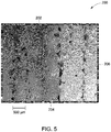
- FIGs 4 and 5 show comparatively high magnification images (than FIG. 2 ) of the as-built alloy 200 of the baseline Rene 80 composition. Specifically, FIGs. 4 and 5 illustrate the as-built alloy 200 of baseline Rene 80 composition with magnification scales of 1 micrometer ( ⁇ m) and 500 nanometers (nm) respectively.
- the carbides 102 that are present in the microstructure of the as-cast alloy 100 of baseline Rene 80 composition as seen in FIG. 3 are distinctly different in their morphology and distribution than the carbides 202 that are present in the microstructure of the as-built alloy 200 of baseline Rene 80 composition as seen in FIGs. 4 and 5 .
- the carbides 102 of the as-cast alloy 100 are relatively large in size as compared to the carbides 202 that are present in the intercolumnar regions 204 of the as-built alloy 200.
- the carbides 102 that are present in the as-cast alloy 100 may have an average diameter of about 2-10 micrometers ( ⁇ m)
- the average diameter of the carbides 202 that are observed in the as-built alloy 200 as seen in FIGs. 4 and 5 are less than about 300 nanometers (nm).
- the carbides 202 that are present in the intercolumnar regions 204 of the as-built alloy of baseline Rene 80 composition are relatively more in number and form substantially closely spaced sections, such as films or arrays of carbides, in the intercolumnar regions 204. Formation of these films or arrays of smaller carbides in the intercolumnar regions 204 of the as-built alloy 200 was unexpected and were hitherto not noticed. By way of example, in as-cast alloy 100, such substantially closely spaced sections are generally not found.
- Ni-base super alloys strengthening mechanisms of Ni-base super alloys are known to be complex and mainly involve precipitation of intermetallic phases and carbides in the grains as well as at the grain boundaries.
- carbides which are found in Ni-base super alloys, namely MC type, M 23 C 6 type, and M 6 C type carbides.
- MC type carbides are carbides with MC composition, where M is a metal and C is carbon.
- MC type carbides are known as primary carbides or solidification-type carbides, and act as a source of carbon for secondary carbides (e.g. carbides of M 23 C 6 and M 6 C type).
- the primary and secondary carbides that are present at the grain boundaries may hinder any movement of dislocations and grain boundaries during formation or service of a component made by the Ni-base super alloys.
- the high number density and close packing of the carbides 202 observed in intercolumnar regions 204 of the as-built alloy 200 may hinder any grain growth during further heat-treatment of the as-built alloy 200.
- the closely spaced carbides 202 may effectively limit stress relaxation of grains through heat-treatment during formation or service of a component made by the as-built alloy 200. Additionally, failure to accommodate stress build-up may result in crack formation in the alloy, thereby compromising mechanical integrity and high temperature properties of the component made by these alloys.
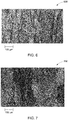
- FIG. 6 illustrates a low magnification microstructure of a Ni-base super alloy 600 that is obtained after heat-treating the as-built alloy 200 of the baseline Rene 80 composition.
- the heat-treatment is carried out at about 1200 °C using hot isotactic pressing (HIP) process.
- HIP hot isotactic pressing
- a Ni-base super alloy 600 of the baseline Rene 80 composition, formed after heat-treatment of the as-built alloy 200 obtained by DMLM process may have substantially anisotropic mechanical properties, such as, for example, anisotropic creep behavior.
- reduction in creep properties and directional variations in creep capabilities of the Ni-base super alloy 600 may not be desirable. Without being bound by any particular theory, the inventors attribute this altered creep behavior to the reduced grain growth during heat-treatment of the as-built alloy 200.
- Ni-base super alloy microstructure that includes substantially equi-axed grains, a matrix of gamma-nickel solid-solution with gamma-prime and a fine dispersion of carbides is desired with the grain-boundaries that are substantially free of embrittling carbide films or phases.
- the creep properties of the Ni-base super alloys 600 may be improved by enabling grain growth of the as-built alloy 200 during heat-treatment. Further, in some embodiments, a grain growth that yields a random orientation is desirable to more closely match the properties of the alloys built by the DMLM process with that of the heat-treated, as-cast alloy.
- recrystallization and grain growth with substantially equi-axial orientation of the grains of the as-built alloy 200 may be formed by reducing the formation of the films or arrays of fine carbides in the intercolumnar regions of the alloys built by the DMLM process.
- Some embodiments described herein are directed towards reducing the carbide content in the intercolumnar regions of the as-built alloy.
- carbide content in the grain boundaries may be reduced by using approaches, such as, but not limited to, reducing the carbon content in an initial reactive powder, reducing a metal content that participates in carbide formation, enabling more primary carbide formation using the available carbon and hindering the secondary carbide formation, directing the available carbon to be reacted with other elements than the material that are prone to form the secondary carbide formation, directing the carbon content to be in the grain regions, or combinations thereof, thereby hindering the grain boundary segregation of carbides.
- approaches such as, but not limited to, reducing the carbon content in an initial reactive powder, reducing a metal content that participates in carbide formation, enabling more primary carbide formation using the available carbon and hindering the secondary carbide formation, directing the available carbon to be reacted with other elements than the material that are prone to form the secondary carbide formation, directing the carbon content to be in the grain regions, or combinations thereof, thereby hindering the grain boundary segregation of carbides.
- Some embodiments described herein are directed at the method of reducing the carbide formation in the grain boundaries by reducing the carbon amount in the initial starting powder along with optional reduction in the percentages of metallic elements that are involved in secondary carbide formation.
- an amount of carbon present in the initial starting powder considered for processing by DMLM process is reduced compared to generally used carbon content in a powder used for forming the Ni-base super alloy. For example, in a Ni-base super alloy having the baseline Rene 80 composition, if the carbon content is in a range from about 0.15 wt.% to about 0.2 wt.%, an altered composition that is used in certain embodiments has a carbon content that is less than 0.15 wt.% of the overall powder composition.
- an amount of a primary carbide-forming element is also reduced, along with reducing the carbon content in the starting powder that is used for the formation of a Ni-base super alloy by the DMLM process.
- an amount of titanium in the starting powder is restricted along with restricting carbon element, to limit the carbide formation in the alloy formed. For example, if the titanium is generally present in a range from about 4.8 wt.% to about 5.2 wt.% in a baseline Rene 80 powder composition used for casting, an altered Rene 80 powder composition that is used in certain embodiments of the present invention has a titanium content that is less than 4.7 wt.% of the overall powder composition.
- Reducing an amount of a primary carbide-forming element, along with reducing carbon content, is particularly beneficial to retain a matrix alloy chemistry of the as-built alloy nominally similar to that of the as-cast alloy of the baseline Rene 80 composition.
- the "matrix alloy chemistry" represents the alloy composition of the matrix phase. Retaining the matrix alloy chemistry is particularly advantageous to substantially avoid changes in some of the alloy chemistry-related properties, such as, for example, phase instabilities, decrease of strength of the formed alloy, and lattice misfit between various phases.
- primary carbide-forming metallic elements include metallic elements that may form primary carbides in the normal processing conditions of forming an as-built alloy using the DMLM process, and where the carbides thus formed are likely to segregate to the intercolumnar regions of the as-built alloy.
- the primary carbide-forming metallic elements may include transition metal elements of group 4A and group 5A of the periodic table.
- Non-limiting examples for the primary carbide-forming metallic elements may include one or more of titanium, zirconium, hafnium, vanadium, niobium, and tantalum.
- reduction in an amount of the primary carbide-forming metallic elements is in addition to the reduction in the carbon level in the starting powder, and may be in proportion to the reduction in the carbon level.
- the reduction in a total atomic percentage of the primary carbide-forming metallic elements is substantially equal to the atomic percentage reduction of carbon in the starting powder.
- the primary carbides that precipitate from the gamma phase matrix in the altered Rene 80 composition are not confined to grain boundaries.
- the primary carbides that precipitate from the gamma phase matrix are well-distributed throughout the microstructure of the as-built alloy, though preferentially distributed in the intercolumnar regions of dendrites.
- the primary carbides that are well-dispersed in the microstructure may re-precipitate into the secondary carbides (M23C6 / M 6 C) during subsequent heat treatment, and may be well-dispersed both in the grains and in the grain boundaries of the heat treated Ni-base super alloy thus formed.
- a method for making the as-built alloy using the DMLM process includes at least partially melting and solidifying a powder that includes about 5 to 15 wt.% of Co, 10 to 20 wt. % of Cr, 3 to 6 wt. % of Mo, 3 to 6 wt. % of W, 2 to 4 wt. % of Al, 4.2 to 4.7 wt. % of Ti, 0.01 to 0.05 wt. % of Zr, 0.015 to 0.060 wt.% of C, and 0.001 to 0.030 wt. % of B and balance substantially Ni.
- the titanium content may be in a range from about 4.2 wt.% to about 4.7 wt.% of the powder, and in some further embodiments, the titanium content may be in a range from about 4.4 wt.% to about 4.6 wt.% of the powder.
- the carbon content may be in a range from about 0.01 wt.% to about 0.04 wt.% of the powder, and in some further embodiments, the titanium content may be in a range from about 0.01 wt.% to about 0.03 wt.% of the powder.
- the selected carbon ranges provided herein particularly aid in reducing dense distribution of carbides in the grain and intercellular boundaries.
- an as-built alloy is formed by using a powder with the altered Rene 80 composition having carbon in a range from about 0.015 wt.% to about 0.060 wt.% and titanium in an amount in a range from about 4.2 wt.% to about 4.7 wt.% of the powder.
- This as-built alloy, formed by using the powder having the above-mentioned altered Rene 80 composition may be referred to as an "intermediate alloy" henceforth, in this application.
- partial melting and solidification may be carried out as part of the DMLM process in building the intermediate alloy.
- the intermediate alloy formed by melting and solidifying the altered Rene 80 composition has columnar regions.
- a columnar region is a region of elongated dendrites having a preferred orientation. Columnar regions may be formed as a result of competitive growth at a particular direction during the solidification step. Intercolumnar regions are the regions between adjacent columnar regions.
- Dendritic growth is a general form of crystal growth encountered when metals, alloys and many other materials solidify under low thermal gradients. The dendritic growth includes columnar regions and intercolumnar regions.
- a dendrite or dendrite structure is generally characterized by the microstructure parameters associated with the dendrites.
- the microstructure of the dendrite structure of the intermediate alloy is normally characterized by primary dendrite or cellular arm spacing.
- a primary dendrite arm spacing is a characteristic length scale that is used to determine segregation pattern in alloy solidification. Generally the primary dendrite arm spacing is obtained by measuring distances between cores (centers) of neighboring dendrites.
- a primary dendrite arm spacing of the dendrite structure of the intermediate alloy is less than about 3 micrometers. In certain embodiments, the primary dendrite arm spacing of the dendrite structure of the intermediate alloy is less than about 2 micrometers.
- a primary dendrite arm spacing of the dendrite structure is less than about 3 micrometers.
- the intermediate alloy has a composition that includes about 5 to 15 wt.% of Co, 10 to 20 wt. % of Cr, 3 to 6 wt. % of Mo, 3 to 6 wt. % of W, 2 to 4 wt. % of Al, 4.2 to 4.7 wt. % of Ti, 0.01 to 0.05 wt. % of Zr, 0.015 to 0.060 wt.% of C, 0.001 to 0.030 wt. % of B and balance substantially Ni.
- the dendrite structure that is formed in the intermediate alloy has only primary arms and arm spacings and may not contain any substantial secondary arms and secondary arm spacings. These dendrite structures that only have the primary arms and arm spacings are referred to as cell structures.
- an amount of the metal carbides present in the intermediate alloy is less than about 0.5 mole% of the composition of the intermediate alloy.
- the initial powder composition that is used for the formation of the intermediate alloy includes carbide formers in an amount such that an equilibrium carbide content of the intermediate alloy is less than about 0.5 mole % at temperatures about the solidus temperature.
- the amount of metal carbides may be further limited to be less than about 0.3 mole% of the intermediate alloy composition.
- the metal carbides that are precipitated in the intermediate alloy may be present both in the columnar and intercolumnar regions. In some embodiments, the metal carbides are disposed in the intercolumnar regions of the intermediate alloy. Metal carbides present in the intercolumnar regions may hinder the grain growth to a greater extent during a heat-treatment as compared to metal carbides that are present within the columnar regions. In some embodiments, an amount of the metal carbides present in the intercolumnar regions of the dendrite structure is less than about 0.3 mole% of the intermediate alloy composition. The amount of metal carbides in the intercolumnar regions may further be limited to be less than about 0.2 mole% of the intermediate alloy composition, in accordance to certain embodiments.
- the method further includes heat-treating the intermediate alloy in a temperature range from about 1050 °C to about 1250 °C to form a texture-free Ni-base super alloy.
- This Ni-base super alloy, formed by heat-treating the intermediate alloy (of altered Rene 80 composition) may be referred to as a "modified Ni-base super alloy" henceforth, in this application.
- composition of the modified Ni-base super alloy is considered to have substantially similar composition as that of the intermediate alloy.
- the matrix alloy composition of the modified Ni-base super alloy is substantially formed in the intermediate alloy form itself.
- the heat-treatment step used for converting the intermediate alloy to the modified Ni-base super alloy is a processing step that is used for altering the microstructure of the intermediate alloy to that of the modified Ni-base super alloy, than for forming the composition of the modified Ni-base super alloy.
- a slight variation in the composition of the intermediate alloy and the modified Ni-base super alloy, if present, may be due to an interaction between the already formed intermediate alloy with the environment. Any such variation in the composition during heat-treatment is limited to less than about 1 volume% of the modified Ni-base super alloy.
- the method includes heat-treating the intermediate alloy in a temperature range from about 1150 °C to about 1250 °C to form the modified Ni-base super alloy.
- the heat-treatment that is imparted to an intermediate alloy having a low carbide content in the intercolumnar regions as noted above allows for a substantial grain growth in the modified Ni-base super alloy thus formed.
- the modified Ni-base super alloy includes grains, grain boundaries, and metal carbides. The metal carbides may be disposed in the grains or the grain boundaries.
- the modified Ni-base super alloy is substantially free of carbides that are precipitated from the melt or liquid state of the alloy.
- the modified Ni-base super alloy includes metal carbides that are precipitated from the solid gamma phase matrix. Further, an equi-axial orientation is observed in the Ni-base super alloy obtained from the powder with modified (lowered) carbon content. Hence the lowered carbon content aids to achieve a substantially modified Ni-base super alloy.
- FIG. 7 illustrates a low magnification microstructure of a modified Ni-base super alloy 700 that is obtained after heat-treating an intermediate alloy.
- the heat-treatment is carried out at about 1200 °C.
- heat-treatment is carried out using hot isotactic pressing (HIP) process.
- HIP hot isotactic pressing
- the heat-treatment disclosed above is particularly directed to form the desired microstructural change in the intermediate alloy to form the modified Ni-base super-alloy, there may be certain other involuntary changes that may occur in the alloy during heat-treatment, such as, for example, change in the gamma-prime phase distribution.
- an additional heat-treatment may be imparted to the heat-treated intermediate alloy to form the modified Ni-base super alloy 700.
- the intermediate alloy may be subjected to the additional treatment to obtain carbide re-precipitation and/or to achieve a preferred gamma-prime distribution.
- FIG. 7 An effect of the amount of carbon or carbide formers in the initial powder can be clearly observed by comparing the microstructure of the modified Ni-base super alloy 700 of FIG. 7 with that of a Ni-base super alloy 600 that is obtained after heat-treating an as-built alloy of the baseline Rene 80 composition, as depicted in FIG. 6 .
- the microstructure of the modified Ni-base super alloy 700 depicts larger and equi-axial grains as compared to the columnar grains with lower grain sizes of the Ni-base super alloy 600.
- the size and orientation of individual grains in the modified Ni-base super alloy 700 were further measured through the use of electron backscatter detection (EBSD) techniques (not shown). EBSD showed that the modified Ni-base super alloy 700 resulted in randomly oriented grains after heat treatment as well as substantial grain growth over the Ni-base super alloy 600 obtained by the baseline Rene 80 composition.
- EBSD electron backscatter detection
- the modified Ni-base super alloy 700 formed by the above-described method is texture-free.
- the "texture-free alloy” is defined as "the alloy, wherein a preferred crystallographic orientation in any direction is less than 20% by volume of any representative region of the alloy considered".
- the crystallographic orientation in the modified Ni-base super alloy 700 is less than 10 volume %, and in certain embodiments, the modified Ni-base super alloy 700 is substantially free of a preferred crystallographic orientation in any particular direction.
- an amount of the metal carbides present in the composition of the modified Ni-base super alloy is less than about 0.5 mole% of the composition.
- the amount of metal carbides may further be limited to be less than about 0.3 mole% of the modified Ni-base super alloy composition, in accordance to certain embodiments.
- the amount of metal carbides in the modified Ni-base super alloy may further be limited to be less than about 0.2 mole% of the modified Ni-base super alloy composition, in accordance to certain embodiments.
- an average size of the metal carbides in the modified Ni-base super alloy may be less than about 1 micrometer.
- the modified Ni-base super alloy formed herein includes a composition that includes about 5 to 15 wt.% of Co, 10 to 20 wt. % of Cr, 3 to 6 wt. % of Mo, 3 to 6 wt. % of W, 2 to 4 wt. % of Al, 4.2 to 4.7 wt. % of Ti, 0.01 to 0.05 wt. % of Zr, 0.015 to 0.060 wt.% of C, 0.001 to 0.030 wt. % of B and balance substantially Ni.
- the modified Ni-base super alloy may be formed by the method described hereinabove and has a texture-free form that includes a gamma phase matrix, a precipitated gamma-prime phase, and metal carbides precipitated from gamma phase matrix.
- the metal carbides that are disposed in the modified Ni-base super alloy is less than about 0.3 mole% of the composition and an average size of the metal carbides that are present in the modified Ni-base super alloy is less than about 1 micrometer.
- the modified Ni-base super alloy has a reduced carbide content in its composition, than just a reduced carbon amount.
- the reduced carbide content aids to maintain a local chemistry of the different phases of (other than carbides) present in the alloy, such as, for example, gamma and gamma-prime phases. Maintaining the local chemistry is particularly advantageous in that the alloy is not susceptible to size alterations and changes in lattice misfit between the matrix and precipitating phases.
Landscapes
- Chemical & Material Sciences (AREA)
- Engineering & Computer Science (AREA)
- Materials Engineering (AREA)
- Physics & Mathematics (AREA)
- Mechanical Engineering (AREA)
- Manufacturing & Machinery (AREA)
- Metallurgy (AREA)
- Organic Chemistry (AREA)
- Thermal Sciences (AREA)
- Plasma & Fusion (AREA)
- Optics & Photonics (AREA)
- Crystallography & Structural Chemistry (AREA)
- Automation & Control Theory (AREA)
- Electromagnetism (AREA)
- Dispersion Chemistry (AREA)
- Power Engineering (AREA)
- Powder Metallurgy (AREA)
- Turbine Rotor Nozzle Sealing (AREA)
Claims (12)
- Procédé, comprenantla fusion et la solidification au moins partiellement d'une poudre comprenant 5 à 15 % en poids de Co, 10 à 20 % en poids de Cr, 3 à 6 % en poids de Mo, 3 à 6 % en poids de W, 2 à 4 % en poids d'AI, 4,2 à 4,7 % en poids de Ti, 0,01 à 0,05 % en poids de Zr, 0,015 à 0,060 % en poids de C, 0,001 à 0,030 % en poids de B et le complément sensiblement de Ni, pour former un alliage intermédiaire (200) comprenant une structure dendritique comprenant des régions colonnaires (206) et des régions intercolonnaires (204), dans lequel un espacement de bras dendritique primaire de la structure dendritique est inférieur à 3 micromètres ; etle traitement thermique de l'alliage intermédiaire (200) dans une plage de températures de 1 050 °C à 1 250 °C pour former un superalliage à base de Ni sans texture (600, 700).
- Procédé selon la revendication 1, dans lequel une quantité de carbures métalliques (202) présents dans une composition de l'alliage intermédiaire (200) est inférieure à 0,5 % en mole de la composition, de préférence inférieure à 0,3 % en mole de la composition.
- Procédé selon la revendication 2, dans lequel les carbures métalliques (202) sont principalement disposés dans les régions intercolonnaires (204) de la structure dendritique.
- Procédé selon la revendication 1, dans lequel le superalliage à base de Ni comprend une matrice en phase gamma.
- Procédé selon la revendication 4, dans lequel le superalliage à base de Ni comprend des précipités d'une phase gamma-prime.
- Procédé selon la revendication 5, dans lequel une quantité de la phase gamma-prime dans le superalliage à base de Ni est supérieure à 40 pour cent en volume.
- Procédé selon la revendication 4, dans lequel le superalliage à base de Ni comprend des carbures métalliques précipités de la matrice en phase gamma.
- Procédé selon la revendication 7, dans lequel une quantité des carbures métalliques présents dans le superalliage à base de Ni est inférieure à 0,3 % en mole de la composition de superalliage à base de Ni.
- Procédé selon la revendication 1, dans lequel le superalliage à base de Ni est exempt de carbures métalliques précipités de la fonte lors de la solidification.
- Alliage intermédiaire (200), comprenantune structure dendritique comprenant des régions colonnaires (206) et des régions intercolonnaires (204), dans lequel un espacement de bras dendritique primaire de la structure dendritique est inférieur à 3 micromètres ; etune composition comprenant 5 à 15 % en poids de Co, 10 à 20 % en poids de Cr, 3 à 6 % en poids de Mo, 3 à 6 % en poids de W, 2 à 4 % en poids d'AI, 4,2 à 4,7 % en poids de Ti, 0,01 à 0,05 % en poids de Zr, 0,015 à 0,060 % en poids de C, 0,001 à 0,030 % en poids de B et le complément sensiblement de Ni.
- Alliage intermédiaire selon la revendication 12, dans lequel une quantité de carbures métalliques (202) présente dans l'alliage intermédiaire (200) est inférieure à 0,5 % en mole de la composition, de préférence inférieure à 0,3 % en mole de la composition.
- Superalliage à base de Ni sans texture (600, 700), comprenantune composition comprenant 5 à 15 % en poids de Co, 10 à 20 % en poids de Cr, 3 à 6 % en poids de Mo, 3 à 6 en poids % de W, 2 à 4 % en poids d'AI, 4,2 à 4,7 % en poids de Ti, 0,01 à 0,05 % en poids de Zr, 0,015 à 0,060 % en poids de C, 0,001 à 0,030 % en poids de B et le complément sensiblement de Ni ;une matrice en phase gamma ;des précipités de phase gamma-prime ; etdes carbures métalliques précipités de la matrice en phase gamma, une quantité des carbures métalliques présents dans le superalliage à base de Ni étant inférieure à 0,3 % en mole du superalliage à base de Ni ; etune taille moyenne des carbures métalliques étant inférieure à 1 micromètre.
Applications Claiming Priority (1)
| Application Number | Priority Date | Filing Date | Title |
|---|---|---|---|
| US14/963,366 US10378087B2 (en) | 2015-12-09 | 2015-12-09 | Nickel base super alloys and methods of making the same |
Publications (2)
| Publication Number | Publication Date |
|---|---|
| EP3185253A1 EP3185253A1 (fr) | 2017-06-28 |
| EP3185253B1 true EP3185253B1 (fr) | 2020-04-29 |
Family
ID=57614121
Family Applications (1)
| Application Number | Title | Priority Date | Filing Date |
|---|---|---|---|
| EP16202589.4A Active EP3185253B1 (fr) | 2015-12-09 | 2016-12-07 | Super alliages à base de nickel et leurs procédés de fabrication |
Country Status (5)
| Country | Link |
|---|---|
| US (2) | US10378087B2 (fr) |
| EP (1) | EP3185253B1 (fr) |
| JP (1) | JP6374939B2 (fr) |
| CN (1) | CN106906382B (fr) |
| CA (1) | CA2949270C (fr) |
Families Citing this family (17)
| Publication number | Priority date | Publication date | Assignee | Title |
|---|---|---|---|---|
| JP6419264B1 (ja) | 2017-07-14 | 2018-11-07 | 東洋インキScホールディングス株式会社 | インキセット、及び印刷物の製造方法 |
| FR3071516B1 (fr) * | 2017-09-25 | 2022-07-29 | Safran Aircraft Engines | Procede de fabrication d'une piece comprenant deux superalliages differents |
| US20190134711A1 (en) * | 2017-11-06 | 2019-05-09 | Dongsheng Li | Method for processing additively manufactured nickel superalloy components with low porosity and high strength |
| WO2019111827A1 (fr) * | 2017-12-06 | 2019-06-13 | 日立金属株式会社 | Procédé de fabrication d'un objet métallique obtenu par fabrication additive, et objet métallique obtenu par fabrication additive |
| JP2021521341A (ja) | 2018-04-25 | 2021-08-26 | シャルマ, サティヤジートSHARMA, Satyajeet | 付加製造のための粉末組成物 |
| US11426818B2 (en) | 2018-08-10 | 2022-08-30 | The Research Foundation for the State University | Additive manufacturing processes and additively manufactured products |
| IT201800010450A1 (it) * | 2018-11-20 | 2020-05-20 | Nuovo Pignone Tecnologie Srl | Metodo per la produzione additiva di un articolo |
| CN110218910A (zh) * | 2018-11-24 | 2019-09-10 | 西部超导材料科技股份有限公司 | 一种新型粉末高温合金及其制备方法 |
| US10577679B1 (en) * | 2018-12-04 | 2020-03-03 | General Electric Company | Gamma prime strengthened nickel superalloy for additive manufacturing |
| DE102019200620A1 (de) * | 2019-01-18 | 2020-07-23 | MTU Aero Engines AG | Verfahren zur Herstellung von Laufschaufeln aus Ni-Basislegierungen und entsprechend hergestellte Laufschaufel |
| US12521794B2 (en) * | 2019-03-04 | 2026-01-13 | Proterial, Ltd. | Ni-based alloy member including additively manufactured body, method for manufacturing Ni-based alloy member, and manufactured product using Ni-based alloy member |
| JP7141967B2 (ja) * | 2019-03-12 | 2022-09-26 | 川崎重工業株式会社 | 造形体製造方法、中間体および造形体 |
| JP7141966B2 (ja) * | 2019-03-12 | 2022-09-26 | 川崎重工業株式会社 | 造形体製造方法および造形体 |
| JP7218225B2 (ja) * | 2019-03-22 | 2023-02-06 | 三菱重工業株式会社 | 積層造形用合金粉末、積層造形物及び積層造形方法 |
| DE102019213214A1 (de) * | 2019-09-02 | 2021-03-04 | Siemens Aktiengesellschaft | Nickelbasissuperlegierung, geeignet auch zur additiven Fertigung, Verfahren und Produkt |
| CN112030040B (zh) * | 2020-07-18 | 2021-10-15 | 北京钢研高纳科技股份有限公司 | 一种高铌含量的高强镍基变形高温合金及其制备方法 |
| IT202400002208A1 (it) * | 2024-02-02 | 2025-08-02 | Nuovo Pignone Tecnologie Srl | Superlega a base di nichel per applicazioni ad alta temperatura tramite produzione additiva |
Citations (1)
| Publication number | Priority date | Publication date | Assignee | Title |
|---|---|---|---|---|
| US20100329876A1 (en) * | 2009-06-30 | 2010-12-30 | General Electric Company | Nickel-base superalloys and components formed thereof |
Family Cites Families (53)
| Publication number | Priority date | Publication date | Assignee | Title |
|---|---|---|---|---|
| US3524744A (en) | 1966-01-03 | 1970-08-18 | Iit Res Inst | Nickel base alloys and process for their manufacture |
| US4169742A (en) | 1976-12-16 | 1979-10-02 | General Electric Company | Cast nickel-base alloy article |
| US4359352A (en) | 1979-11-19 | 1982-11-16 | Marko Materials, Inc. | Nickel base superalloys which contain boron and have been processed by a rapid solidification process |
| US4624716A (en) | 1982-12-13 | 1986-11-25 | Armco Inc. | Method of treating a nickel base alloy |
| US4708750A (en) | 1985-12-23 | 1987-11-24 | United Technologies Corporation | Thermal treatment of wrought, nickel base superalloys in conjunction with high energy hole drilling |
| JP2778705B2 (ja) | 1988-09-30 | 1998-07-23 | 日立金属株式会社 | Ni基超耐熱合金およびその製造方法 |
| US5584947A (en) | 1994-08-18 | 1996-12-17 | General Electric Company | Method for forming a nickel-base superalloy having improved resistance to abnormal grain growth |
| US5725692A (en) * | 1995-10-02 | 1998-03-10 | United Technologies Corporation | Nickel base superalloy articles with improved resistance to crack propagation |
| GB0024031D0 (en) | 2000-09-29 | 2000-11-15 | Rolls Royce Plc | A nickel base superalloy |
| US6495793B2 (en) | 2001-04-12 | 2002-12-17 | General Electric Company | Laser repair method for nickel base superalloys with high gamma prime content |
| US6969431B2 (en) | 2003-08-29 | 2005-11-29 | Honeywell International, Inc. | High temperature powder metallurgy superalloy with enhanced fatigue and creep resistance |
| US6866727B1 (en) | 2003-08-29 | 2005-03-15 | Honeywell International, Inc. | High temperature powder metallurgy superalloy with enhanced fatigue and creep resistance |
| US7708846B2 (en) | 2005-11-28 | 2010-05-04 | United Technologies Corporation | Superalloy stabilization |
| FR2899240B1 (fr) | 2006-03-31 | 2008-06-27 | Snecma Sa | Alliage a base de nickel |
| GB0616116D0 (en) | 2006-08-12 | 2006-09-20 | Rolls Royce Plc | A method of forming a component on a substrate |
| EP2066973A1 (fr) | 2007-03-30 | 2009-06-10 | Corning Incorporated | Brûleurs microfabriqués tridimensionnels |
| US20130230405A1 (en) | 2007-08-31 | 2013-09-05 | Kevin Swayne O'Hara | Nickel base superalloy compositions being substantially free of rhenium and superalloy articles |
| WO2009149300A1 (fr) | 2008-06-04 | 2009-12-10 | Sixpoint Materials | Récipient sous haute pression pour faire croître des cristaux de nitrure de groupe iii et procédé destiné à faire croître des cristaux de nitrure de groupe iii à l’aide d’un récipient sous haute pression et d’un cristal de nitrure de groupe iii |
| US8231730B2 (en) | 2008-06-09 | 2012-07-31 | Guardian Industries Corp. | Combustion deposition burner and/or related methods |
| DE102009049707A1 (de) | 2009-10-17 | 2011-07-28 | MTU Aero Engines GmbH, 80995 | Verfahren zur Herstellung einer Lauf- oder Statorschaufel und eine derartige Schaufel |
| WO2012047352A2 (fr) | 2010-07-09 | 2012-04-12 | General Electric Company | Alliage à base de nickel, son traitement et les composants formés à partir dudit alliage |
| US8793871B2 (en) | 2011-03-17 | 2014-08-05 | Siemens Energy, Inc. | Process for making a wall with a porous element for component cooling |
| US8506836B2 (en) | 2011-09-16 | 2013-08-13 | Honeywell International Inc. | Methods for manufacturing components from articles formed by additive-manufacturing processes |
| CH705631A1 (de) | 2011-10-31 | 2013-05-15 | Alstom Technology Ltd | Komponenten oder Coupon zur Verwendung unter hoher thermischer und Spannungslast und Verfahren zur Herstellung einer solchen Komponente oder eines solchen Coupons. |
| CH705750A1 (de) | 2011-10-31 | 2013-05-15 | Alstom Technology Ltd | Verfahren zur Herstellung von Komponenten oder Abschnitten, die aus einer Hochtemperatur-Superlegierung bestehen. |
| CH705662A1 (de) | 2011-11-04 | 2013-05-15 | Alstom Technology Ltd | Prozess zur Herstellung von Gegenständen aus einer durch Gamma-Prime-Ausscheidung verfestigten Superlegierung auf Nickelbasis durch selektives Laserschmelzen (SLM). |
| US9527162B2 (en) | 2011-11-07 | 2016-12-27 | Siemens Energy, Inc. | Laser additive repairing of nickel base superalloy components |
| EP2790858B1 (fr) | 2011-12-14 | 2017-02-08 | General Electric Technology GmbH | Procédé de fabrication additive d'un article composé d'un matériau difficile à souder |
| US9266170B2 (en) | 2012-01-27 | 2016-02-23 | Honeywell International Inc. | Multi-material turbine components |
| US8984752B2 (en) | 2012-06-06 | 2015-03-24 | Xerox Corporation | Printhead fabrication using additive manufacturing techniques |
| FR2991613B1 (fr) | 2012-06-06 | 2016-11-11 | Snecma | Procede de fabrication de piece par fusion selective ou frittage selectif de lits de poudre(s) au moyen d'un faisceau de haute energie |
| CA2878711A1 (fr) | 2012-07-12 | 2014-04-17 | General Electric Company | Superalliage a base de nickel, traitement associe et composants formes a partir de celui-ci |
| GB201213940D0 (en) | 2012-08-06 | 2012-09-19 | Materials Solutions | Additive manufacturing |
| US9289826B2 (en) | 2012-09-17 | 2016-03-22 | Honeywell International Inc. | Turbine stator airfoil assemblies and methods for their manufacture |
| US20140216042A1 (en) | 2012-09-28 | 2014-08-07 | United Technologies Corporation | Combustor component with cooling holes formed by additive manufacturing |
| EP2900964A4 (fr) | 2012-09-28 | 2016-06-29 | United Technologies Corp | Composant de section de turbine surrefroidie fabriqué par fabrication additive |
| CN109937387B (zh) | 2012-11-08 | 2022-08-23 | Ddm系统有限责任公司 | 金属部件的增材制造及维修 |
| US9393620B2 (en) | 2012-12-14 | 2016-07-19 | United Technologies Corporation | Uber-cooled turbine section component made by additive manufacturing |
| US20140170012A1 (en) | 2012-12-18 | 2014-06-19 | United Technologies Corporation | Additive manufacturing using partially sintered layers |
| US9393644B2 (en) | 2013-01-31 | 2016-07-19 | Siemens Energy, Inc. | Cladding of alloys using flux and metal powder cored feed material |
| US20140209576A1 (en) | 2013-01-31 | 2014-07-31 | Kazim Ozbaysal | Use of elevated pressures for reducing cracks in superalloy welding and cladding |
| US10190220B2 (en) | 2013-01-31 | 2019-01-29 | Siemens Energy, Inc. | Functional based repair of superalloy components |
| US8640942B1 (en) | 2013-03-13 | 2014-02-04 | Siemens Energy, Inc. | Repair of superalloy component |
| EP2781691A1 (fr) | 2013-03-19 | 2014-09-24 | Alstom Technology Ltd | Procédé de reconditionnement d'une partie de la trajectoire des gaz chauds d'une turbine à gaz |
| EP2789597B1 (fr) | 2013-04-12 | 2017-11-15 | Ansaldo Energia IP UK Limited | Méthode pour obtenir une configuration pour assembler un matériau d'isolation thermique en céramique à une structure métallique |
| US9415438B2 (en) | 2013-04-19 | 2016-08-16 | United Technologies Corporation | Method for forming single crystal parts using additive manufacturing and remelt |
| CN103668461A (zh) | 2013-09-21 | 2014-03-26 | 北京工业大学 | 一种镍基超合金Rene80定向生长柱晶及单晶合金制备及零部件制造方法 |
| WO2015047128A1 (fr) | 2013-09-27 | 2015-04-02 | Siemens Aktiengesellschaft | Procédé de fabrication d'alliage à base de nickel comprenant un post-traitement thermique et élément comportant l'alliage à base de nickel |
| EP2886225B1 (fr) | 2013-12-23 | 2017-06-07 | Ansaldo Energia IP UK Limited | Précipitation gamma prime renforcée par un superalliage à base de nickel destinée à être utilisée dans un processus de fabrication d'additif à base de poudre |
| CN105163898A (zh) | 2013-12-24 | 2015-12-16 | 利宝地工程有限公司 | 熔焊高温合金的沉淀强化的镍基焊接材料 |
| EP2944402B1 (fr) | 2014-05-12 | 2019-04-03 | Ansaldo Energia IP UK Limited | Post traitement thermique de composants en superalliage renforcé par phase gamme prime fabriqués de manière additive |
| EP2949768B1 (fr) | 2014-05-28 | 2019-07-17 | Ansaldo Energia IP UK Limited | Précipitation gamma prime renforcée par un superalliage à base de nickel destinée à être utilisée dans un processus de fabrication d'additif à base de poudre |
| CN104911407B (zh) | 2015-06-29 | 2017-06-16 | 沈阳工业大学 | 一种含Re/Ru高承温能力高蠕变抗力单晶镍基超合金 |
-
2015
- 2015-12-09 US US14/963,366 patent/US10378087B2/en active Active
-
2016
- 2016-11-22 CA CA2949270A patent/CA2949270C/fr active Active
- 2016-12-02 JP JP2016234615A patent/JP6374939B2/ja active Active
- 2016-12-07 EP EP16202589.4A patent/EP3185253B1/fr active Active
- 2016-12-09 CN CN201611128355.4A patent/CN106906382B/zh active Active
-
2018
- 2018-12-15 US US16/221,452 patent/US10801088B2/en active Active
Patent Citations (1)
| Publication number | Priority date | Publication date | Assignee | Title |
|---|---|---|---|---|
| US20100329876A1 (en) * | 2009-06-30 | 2010-12-30 | General Electric Company | Nickel-base superalloys and components formed thereof |
Also Published As
| Publication number | Publication date |
|---|---|
| JP6374939B2 (ja) | 2018-08-15 |
| US20170167000A1 (en) | 2017-06-15 |
| CN106906382B (zh) | 2019-05-14 |
| US10378087B2 (en) | 2019-08-13 |
| CN106906382A (zh) | 2017-06-30 |
| US10801088B2 (en) | 2020-10-13 |
| CA2949270A1 (fr) | 2017-06-09 |
| US20200024699A1 (en) | 2020-01-23 |
| JP2017137567A (ja) | 2017-08-10 |
| CA2949270C (fr) | 2022-02-01 |
| EP3185253A1 (fr) | 2017-06-28 |
Similar Documents
| Publication | Publication Date | Title |
|---|---|---|
| US10801088B2 (en) | Nickel base super alloys and methods of making the same | |
| Haines et al. | Powder bed fusion additive manufacturing of Ni-based superalloys: a review of the main microstructural constituents and characterization techniques | |
| US10221468B2 (en) | Article and additive manufacturing method for making | |
| JP6509290B2 (ja) | コバルト基合金積層造形体、コバルト基合金製造物、およびそれらの製造方法 | |
| JP7012459B2 (ja) | Ni基超合金組成物、及びかかるNi基超合金組成物をSLM加工するための方法 | |
| Engeli et al. | Processability of different IN738LC powder batches by selective laser melting | |
| Carter | Selective laser melting of nickel superalloys for high temperature applications | |
| KR20140025282A (ko) | 3차원 물품을 제조하기 위한 방법 | |
| JP7337908B2 (ja) | ニッケル基合金粉末 | |
| WO2020121367A1 (fr) | Corps moulé stratifié en alliage à base de cobalt, produit en alliage à base de cobalt et leur procédé de fabrication | |
| WO2020179085A1 (fr) | Échangeur de chaleur | |
| Basak | Additive manufacturing of high-gamma prime nickel-based superalloys through selective laser melting (SLM) | |
| JP2010075999A (ja) | 方向性凝固法及び該方法で製造される鋳造品 | |
| Kumar et al. | Influence of double aging heat treatment on phase transformation and dimensional accuracy of Inconel 718 alloy made through laser-based additive manufacturing | |
| Gong et al. | Progress in additive manufacturing of nickel-based superalloys: materials, processing, microstructures, properties and alloy design: L. Gong et al. | |
| Jahangiri | Influence of cooling rate during solidification on microstructural features and γ′ size and morphology in cast IN939 superalloy | |
| CN111373063A (zh) | 具有高抗氧化性的用于燃气涡轮应用的合金 | |
| Forsik et al. | Influence of the γ/γ′ Misfit on the Strain-Age Cracking Resistance of High-γ′ Ni and CoNi Superalloys for Additive Manufacturing | |
| CN120322305A (zh) | 用于增材制造的单相镍合金 | |
| Basak et al. | Microstructural characterization of MAR-M247 fabricated through scanning laser epitaxy | |
| EP4559598A1 (fr) | Articles fabriqués de manière additive ayant une microstructure présentant une fraction de volume gamma prime élevé | |
| JP7355189B2 (ja) | Ni基合金積層造形物 | |
| Marchese et al. | Microstructural investigation of heat treated inconel 625 fabricated through direct metal laser sintering | |
| Ramakrishnan-Sudha | Direct Laser Metal Deposition of Nickel Based Superalloys | |
| Niu et al. | Effect of Hot Isostatic Pressing Temperature on the Microstructure and Mechanical Properties of K4169 Superalloy Formed by Laser Powder Bed Fusion |
Legal Events
| Date | Code | Title | Description |
|---|---|---|---|
| PUAI | Public reference made under article 153(3) epc to a published international application that has entered the european phase |
Free format text: ORIGINAL CODE: 0009012 |
|
| STAA | Information on the status of an ep patent application or granted ep patent |
Free format text: STATUS: THE APPLICATION HAS BEEN PUBLISHED |
|
| AK | Designated contracting states |
Kind code of ref document: A1 Designated state(s): AL AT BE BG CH CY CZ DE DK EE ES FI FR GB GR HR HU IE IS IT LI LT LU LV MC MK MT NL NO PL PT RO RS SE SI SK SM TR |
|
| AX | Request for extension of the european patent |
Extension state: BA ME |
|
| STAA | Information on the status of an ep patent application or granted ep patent |
Free format text: STATUS: REQUEST FOR EXAMINATION WAS MADE |
|
| 17P | Request for examination filed |
Effective date: 20180102 |
|
| RBV | Designated contracting states (corrected) |
Designated state(s): AL AT BE BG CH CY CZ DE DK EE ES FI FR GB GR HR HU IE IS IT LI LT LU LV MC MK MT NL NO PL PT RO RS SE SI SK SM TR |
|
| GRAP | Despatch of communication of intention to grant a patent |
Free format text: ORIGINAL CODE: EPIDOSNIGR1 |
|
| STAA | Information on the status of an ep patent application or granted ep patent |
Free format text: STATUS: GRANT OF PATENT IS INTENDED |
|
| RIC1 | Information provided on ipc code assigned before grant |
Ipc: H01F 1/147 20060101AFI20191021BHEP Ipc: B22F 3/105 20060101ALI20191021BHEP Ipc: C22C 19/05 20060101ALI20191021BHEP |
|
| INTG | Intention to grant announced |
Effective date: 20191112 |
|
| GRAS | Grant fee paid |
Free format text: ORIGINAL CODE: EPIDOSNIGR3 |
|
| GRAA | (expected) grant |
Free format text: ORIGINAL CODE: 0009210 |
|
| STAA | Information on the status of an ep patent application or granted ep patent |
Free format text: STATUS: THE PATENT HAS BEEN GRANTED |
|
| AK | Designated contracting states |
Kind code of ref document: B1 Designated state(s): AL AT BE BG CH CY CZ DE DK EE ES FI FR GB GR HR HU IE IS IT LI LT LU LV MC MK MT NL NO PL PT RO RS SE SI SK SM TR |
|
| REG | Reference to a national code |
Ref country code: GB Ref legal event code: FG4D |
|
| REG | Reference to a national code |
Ref country code: CH Ref legal event code: EP |
|
| REG | Reference to a national code |
Ref country code: AT Ref legal event code: REF Ref document number: 1264527 Country of ref document: AT Kind code of ref document: T Effective date: 20200515 |
|
| REG | Reference to a national code |
Ref country code: DE Ref legal event code: R096 Ref document number: 602016034983 Country of ref document: DE |
|
| REG | Reference to a national code |
Ref country code: IE Ref legal event code: FG4D |
|
| REG | Reference to a national code |
Ref country code: NL Ref legal event code: MP Effective date: 20200429 |
|
| REG | Reference to a national code |
Ref country code: LT Ref legal event code: MG4D |
|
| PG25 | Lapsed in a contracting state [announced via postgrant information from national office to epo] |
Ref country code: LT Free format text: LAPSE BECAUSE OF FAILURE TO SUBMIT A TRANSLATION OF THE DESCRIPTION OR TO PAY THE FEE WITHIN THE PRESCRIBED TIME-LIMIT Effective date: 20200429 Ref country code: PT Free format text: LAPSE BECAUSE OF FAILURE TO SUBMIT A TRANSLATION OF THE DESCRIPTION OR TO PAY THE FEE WITHIN THE PRESCRIBED TIME-LIMIT Effective date: 20200831 Ref country code: GR Free format text: LAPSE BECAUSE OF FAILURE TO SUBMIT A TRANSLATION OF THE DESCRIPTION OR TO PAY THE FEE WITHIN THE PRESCRIBED TIME-LIMIT Effective date: 20200730 Ref country code: FI Free format text: LAPSE BECAUSE OF FAILURE TO SUBMIT A TRANSLATION OF THE DESCRIPTION OR TO PAY THE FEE WITHIN THE PRESCRIBED TIME-LIMIT Effective date: 20200429 Ref country code: SE Free format text: LAPSE BECAUSE OF FAILURE TO SUBMIT A TRANSLATION OF THE DESCRIPTION OR TO PAY THE FEE WITHIN THE PRESCRIBED TIME-LIMIT Effective date: 20200429 Ref country code: IS Free format text: LAPSE BECAUSE OF FAILURE TO SUBMIT A TRANSLATION OF THE DESCRIPTION OR TO PAY THE FEE WITHIN THE PRESCRIBED TIME-LIMIT Effective date: 20200829 Ref country code: NO Free format text: LAPSE BECAUSE OF FAILURE TO SUBMIT A TRANSLATION OF THE DESCRIPTION OR TO PAY THE FEE WITHIN THE PRESCRIBED TIME-LIMIT Effective date: 20200729 |
|
| REG | Reference to a national code |
Ref country code: AT Ref legal event code: MK05 Ref document number: 1264527 Country of ref document: AT Kind code of ref document: T Effective date: 20200429 |
|
| PG25 | Lapsed in a contracting state [announced via postgrant information from national office to epo] |
Ref country code: RS Free format text: LAPSE BECAUSE OF FAILURE TO SUBMIT A TRANSLATION OF THE DESCRIPTION OR TO PAY THE FEE WITHIN THE PRESCRIBED TIME-LIMIT Effective date: 20200429 Ref country code: BG Free format text: LAPSE BECAUSE OF FAILURE TO SUBMIT A TRANSLATION OF THE DESCRIPTION OR TO PAY THE FEE WITHIN THE PRESCRIBED TIME-LIMIT Effective date: 20200729 Ref country code: LV Free format text: LAPSE BECAUSE OF FAILURE TO SUBMIT A TRANSLATION OF THE DESCRIPTION OR TO PAY THE FEE WITHIN THE PRESCRIBED TIME-LIMIT Effective date: 20200429 Ref country code: HR Free format text: LAPSE BECAUSE OF FAILURE TO SUBMIT A TRANSLATION OF THE DESCRIPTION OR TO PAY THE FEE WITHIN THE PRESCRIBED TIME-LIMIT Effective date: 20200429 |
|
| PG25 | Lapsed in a contracting state [announced via postgrant information from national office to epo] |
Ref country code: AL Free format text: LAPSE BECAUSE OF FAILURE TO SUBMIT A TRANSLATION OF THE DESCRIPTION OR TO PAY THE FEE WITHIN THE PRESCRIBED TIME-LIMIT Effective date: 20200429 Ref country code: NL Free format text: LAPSE BECAUSE OF FAILURE TO SUBMIT A TRANSLATION OF THE DESCRIPTION OR TO PAY THE FEE WITHIN THE PRESCRIBED TIME-LIMIT Effective date: 20200429 |
|
| PG25 | Lapsed in a contracting state [announced via postgrant information from national office to epo] |
Ref country code: RO Free format text: LAPSE BECAUSE OF FAILURE TO SUBMIT A TRANSLATION OF THE DESCRIPTION OR TO PAY THE FEE WITHIN THE PRESCRIBED TIME-LIMIT Effective date: 20200429 Ref country code: EE Free format text: LAPSE BECAUSE OF FAILURE TO SUBMIT A TRANSLATION OF THE DESCRIPTION OR TO PAY THE FEE WITHIN THE PRESCRIBED TIME-LIMIT Effective date: 20200429 Ref country code: SM Free format text: LAPSE BECAUSE OF FAILURE TO SUBMIT A TRANSLATION OF THE DESCRIPTION OR TO PAY THE FEE WITHIN THE PRESCRIBED TIME-LIMIT Effective date: 20200429 Ref country code: DK Free format text: LAPSE BECAUSE OF FAILURE TO SUBMIT A TRANSLATION OF THE DESCRIPTION OR TO PAY THE FEE WITHIN THE PRESCRIBED TIME-LIMIT Effective date: 20200429 Ref country code: IT Free format text: LAPSE BECAUSE OF FAILURE TO SUBMIT A TRANSLATION OF THE DESCRIPTION OR TO PAY THE FEE WITHIN THE PRESCRIBED TIME-LIMIT Effective date: 20200429 Ref country code: AT Free format text: LAPSE BECAUSE OF FAILURE TO SUBMIT A TRANSLATION OF THE DESCRIPTION OR TO PAY THE FEE WITHIN THE PRESCRIBED TIME-LIMIT Effective date: 20200429 Ref country code: CZ Free format text: LAPSE BECAUSE OF FAILURE TO SUBMIT A TRANSLATION OF THE DESCRIPTION OR TO PAY THE FEE WITHIN THE PRESCRIBED TIME-LIMIT Effective date: 20200429 Ref country code: ES Free format text: LAPSE BECAUSE OF FAILURE TO SUBMIT A TRANSLATION OF THE DESCRIPTION OR TO PAY THE FEE WITHIN THE PRESCRIBED TIME-LIMIT Effective date: 20200429 |
|
| REG | Reference to a national code |
Ref country code: DE Ref legal event code: R097 Ref document number: 602016034983 Country of ref document: DE |
|
| PG25 | Lapsed in a contracting state [announced via postgrant information from national office to epo] |
Ref country code: PL Free format text: LAPSE BECAUSE OF FAILURE TO SUBMIT A TRANSLATION OF THE DESCRIPTION OR TO PAY THE FEE WITHIN THE PRESCRIBED TIME-LIMIT Effective date: 20200429 Ref country code: SK Free format text: LAPSE BECAUSE OF FAILURE TO SUBMIT A TRANSLATION OF THE DESCRIPTION OR TO PAY THE FEE WITHIN THE PRESCRIBED TIME-LIMIT Effective date: 20200429 |
|
| PLBE | No opposition filed within time limit |
Free format text: ORIGINAL CODE: 0009261 |
|
| STAA | Information on the status of an ep patent application or granted ep patent |
Free format text: STATUS: NO OPPOSITION FILED WITHIN TIME LIMIT |
|
| 26N | No opposition filed |
Effective date: 20210201 |
|
| PG25 | Lapsed in a contracting state [announced via postgrant information from national office to epo] |
Ref country code: SI Free format text: LAPSE BECAUSE OF FAILURE TO SUBMIT A TRANSLATION OF THE DESCRIPTION OR TO PAY THE FEE WITHIN THE PRESCRIBED TIME-LIMIT Effective date: 20200429 |
|
| REG | Reference to a national code |
Ref country code: CH Ref legal event code: PL |
|
| PG25 | Lapsed in a contracting state [announced via postgrant information from national office to epo] |
Ref country code: MC Free format text: LAPSE BECAUSE OF FAILURE TO SUBMIT A TRANSLATION OF THE DESCRIPTION OR TO PAY THE FEE WITHIN THE PRESCRIBED TIME-LIMIT Effective date: 20200429 |
|
| REG | Reference to a national code |
Ref country code: BE Ref legal event code: MM Effective date: 20201231 |
|
| PG25 | Lapsed in a contracting state [announced via postgrant information from national office to epo] |
Ref country code: IE Free format text: LAPSE BECAUSE OF NON-PAYMENT OF DUE FEES Effective date: 20201207 Ref country code: LU Free format text: LAPSE BECAUSE OF NON-PAYMENT OF DUE FEES Effective date: 20201207 |
|
| PG25 | Lapsed in a contracting state [announced via postgrant information from national office to epo] |
Ref country code: LI Free format text: LAPSE BECAUSE OF NON-PAYMENT OF DUE FEES Effective date: 20201231 Ref country code: CH Free format text: LAPSE BECAUSE OF NON-PAYMENT OF DUE FEES Effective date: 20201231 |
|
| PG25 | Lapsed in a contracting state [announced via postgrant information from national office to epo] |
Ref country code: TR Free format text: LAPSE BECAUSE OF FAILURE TO SUBMIT A TRANSLATION OF THE DESCRIPTION OR TO PAY THE FEE WITHIN THE PRESCRIBED TIME-LIMIT Effective date: 20200429 Ref country code: MT Free format text: LAPSE BECAUSE OF FAILURE TO SUBMIT A TRANSLATION OF THE DESCRIPTION OR TO PAY THE FEE WITHIN THE PRESCRIBED TIME-LIMIT Effective date: 20200429 Ref country code: CY Free format text: LAPSE BECAUSE OF FAILURE TO SUBMIT A TRANSLATION OF THE DESCRIPTION OR TO PAY THE FEE WITHIN THE PRESCRIBED TIME-LIMIT Effective date: 20200429 |
|
| PG25 | Lapsed in a contracting state [announced via postgrant information from national office to epo] |
Ref country code: MK Free format text: LAPSE BECAUSE OF FAILURE TO SUBMIT A TRANSLATION OF THE DESCRIPTION OR TO PAY THE FEE WITHIN THE PRESCRIBED TIME-LIMIT Effective date: 20200429 |
|
| PG25 | Lapsed in a contracting state [announced via postgrant information from national office to epo] |
Ref country code: BE Free format text: LAPSE BECAUSE OF NON-PAYMENT OF DUE FEES Effective date: 20201231 |
|
| P01 | Opt-out of the competence of the unified patent court (upc) registered |
Effective date: 20230515 |
|
| PGFP | Annual fee paid to national office [announced via postgrant information from national office to epo] |
Ref country code: DE Payment date: 20251126 Year of fee payment: 10 |
|
| PGFP | Annual fee paid to national office [announced via postgrant information from national office to epo] |
Ref country code: GB Payment date: 20251119 Year of fee payment: 10 |
|
| PGFP | Annual fee paid to national office [announced via postgrant information from national office to epo] |
Ref country code: FR Payment date: 20251120 Year of fee payment: 10 |