EP3186183B1 - Einrichtung zum betätigen einer kabinen- und schachttür einer aufzugsanlage - Google Patents
Einrichtung zum betätigen einer kabinen- und schachttür einer aufzugsanlage Download PDFInfo
- Publication number
- EP3186183B1 EP3186183B1 EP15753370.4A EP15753370A EP3186183B1 EP 3186183 B1 EP3186183 B1 EP 3186183B1 EP 15753370 A EP15753370 A EP 15753370A EP 3186183 B1 EP3186183 B1 EP 3186183B1
- Authority
- EP
- European Patent Office
- Prior art keywords
- door
- plate unit
- coupling
- cabin
- counter
- Prior art date
- Legal status (The legal status is an assumption and is not a legal conclusion. Google has not performed a legal analysis and makes no representation as to the accuracy of the status listed.)
- Active
Links
Images


Classifications
-
- B—PERFORMING OPERATIONS; TRANSPORTING
- B66—HOISTING; LIFTING; HAULING
- B66B—ELEVATORS; ESCALATORS OR MOVING WALKWAYS
- B66B13/00—Doors, gates, or other apparatus controlling access to, or exit from, cages or lift well landings
- B66B13/02—Door or gate operation
- B66B13/12—Arrangements for effecting simultaneous opening or closing of cage and landing doors
-
- B—PERFORMING OPERATIONS; TRANSPORTING
- B66—HOISTING; LIFTING; HAULING
- B66B—ELEVATORS; ESCALATORS OR MOVING WALKWAYS
- B66B13/00—Doors, gates, or other apparatus controlling access to, or exit from, cages or lift well landings
- B66B13/02—Door or gate operation
- B66B13/06—Door or gate operation of sliding doors
- B66B13/08—Door or gate operation of sliding doors guided for horizontal movement
Definitions
- the invention relates to a device preferably for an elevator system for actuating at least one car or shaft door according to the preamble of claim 1.
- a known elevator In a known elevator according to the document EP-A-2 297 018 is an elevator car with horizontally displaceable cabin door panels and provided at the floors with corresponding landing door panels in a known manner, these doors are arranged parallel to each other.
- a coupling device is provided which comprises a transfer of the corresponding movements on the shaft door panel and to at least one displaceable cam member is provided, which is brought into contact with a present on the shaft door panel counter element.
- the car door sash is associated with a door lock with a car door latch and a bolt stop. A blocking effect of this door lock is dependent on the interaction of the coupling device with the counter element. This is monitored by an elevator control which, by means of an existing safety switch on the door lock, prevents the door from opening when the elevator car is not exactly at the floor level.
- the movement of the car door bolt is rigidly coupled to that of the driver element.
- the driver element When the driver element in a distanced from the counter element of the shaft door wing driving position or moved further than up to a defined coupling position, the car door latch blocks an opening of the bolt stop and thus the car door leaf. On the other hand, the latter can be opened when the driver element is stopped by the counter element in a defined coupling position.
- driver elements of a car door leaf between two counter-elements of the shaft door leaf are provided when the elevator car is at floor level, the driver elements are pressed by a spring against the counter-elements before an opening of the cabin door leaf begins.
- a driver system arranged on the car door which can be moved by a movement mechanism in the horizontal direction along or transversely to the car door and can be coupled to the shaft door by means of a magnet.
- This movement mechanism is pivoted by means of an actuator primarily in the direction of the door plane and this horizontally.
- the magnet is displaced by means of a driver control in the same direction against a cam curve until the driver system with a regulated adhesive force on a sliding surface of the cam curve and thus the doors are coupled so that they can be opened or closed together.
- EP-A-0 829 447 discloses a device for entraining shaft doors in an elevator, in which a movement mechanism is provided with a lever arrangement by which a driver is displaced in a direction perpendicular to the door planes direction. By means of an electromagnet, the driver is brought into engagement with the coupling part after the movement mechanism has the same adjusted until a set air gap between the electromagnet and the coupling part has been reached.
- a disadvantage of these devices is the complex mechanism for this entrainment of the doors, in which this movement mechanism and this electromagnet are provided and thus accurate control must be made both to the movement and to the positioning of the movement mechanism and to the electromagnet.
- the invention has for its object to provide a means for actuating at least one car or shaft door, which offers a space-saving and safe construction in fulfillment of all the necessary functions for the operation of a lift.
- the coupling mechanism for the car door comprises a transversely adjustable to the car door coupling element which is movable from a retracted position into a coupled to a counter element of the plate unit for the shaft door position.
- This inventive structure of the device allows a perfect function in the operation of an elevator system, even if there are operational problems.
- an opening or closing of the cabin and the shaft door can be accomplished in a simple manner.
- One of the significant advantages is also that with the inventive structure of the device compared to the known elevators a reduction of the gap between the cabin and the shaft can be achieved on the door side, which can be reduced from about 30 to 10 mm. This is in addition to an optical improvement also reduces the risk that narrow objects, such as keys, money or like that, can hardly fall through this gap in the elevator shaft.
- This adjustable coupling element of the coupling mechanism and the counter element of the plate unit are very advantageously designed as magnetic plates, by means of which a sufficient adhesive force can be generated in the coupled position. As a result, a coupling can be done very efficiently and safely and by this retraction of the coupling element no space is required for closed doors.
- This inventive device is also suitable for retrofitting and modernization of existing elevator systems.
- the associated changing and high tolerances between the elevator car and the elevator shaft or the shaft walls due to structural subsidence, changing dimensions, etc. can be easily compensated for in older or very tall buildings.
- a lift shaft 11 In a partially illustrated elevator installation 10 according to Fig. 1 is a lift shaft 11 and a guided in this run up and down movable cab 15 indicated. This held in a known manner by ropes or the like cab can be performed in the elevator shaft 11 to the individual floors 12 by an appropriate control.
- Such elevator systems are mainly installed in houses, office buildings, commercial buildings or the like and they are used for the carriage of persons, animals and / or objects of all kinds. It is particularly suitable for elevator systems, with at least partially extending in the horizontal direction shafts are built.
- Both in the cabin 15 as well as at the respective floors 12 are each at least one car door 16 and a shaft door 13 is provided, which can be opened or closed transversely to the image plane.
- a shaft door 13 is provided, which can be opened or closed transversely to the image plane.
- the doors 13, 16 are assigned on their upper side rollers 14, 38, which are guided via connecting elements 21, 39 on fixed guide rails 14 ', 38' on the one hand to the cabin 15 and on the other hand in the shaft wall 11 '.
- these doors 13, 16 are advantageously guided in longitudinal guides 13 ', 16'.
- a device 20 for actuating the car or shaft door 13, 16 is advantageously placed on the top of the cabin 15.
- a control-actuatable drive motor 17 is arranged on the cabin upper side, which usually drives a circulating toothed belt as the drive element 18 for the doors 13, 16.
- Fig. 2 and Fig. 3 show a coupling mechanism 25 of the device 20, which is fastened to the sliding cabin door 16 and in the assembled state, as in Fig. 1 can be seen, is arranged in a vertical orientation.
- the partially shown guide rail 14 ' is horizontally mounted in the drive motor 17 in its longitudinal extent and the in Fig. 1 indicated rollers 14 are rotatably mounted in a fastened to the car door 16 base plate 21.
- the coupling mechanism 25 has a coupling element 24 which can be displaced transversely to this or to the car door 16 and which moves from a retracted position, as in FIG Fig. 2 can be seen in a coupled with a counter element of the disk unit 40 position, as in Fig. 3 is shown, is movable.
- the adjustable coupling element 24 of the coupling mechanism 25 and the counter element 44 of the plate unit 40 are each formed as a magnetic plate, through which in the coupled position sufficient adhesive force can be generated, which can be supported by compression springs, not shown.
- the coupling element 24 consists of one or more magnets. This can be a fast and effective coupling between cabin and shaft door bring about.
- the coupling mechanism 25 comprises an adjusting device 26 for the coupling element 24, a rocker 22 which can be connected to the drive element 18 of the door drive by a clamp 31, and a pivotable transmission element 23, which are arranged on the base plate 21.
- the adjusting device 26 is provided with a carriage 27 with at least one, in the present two guide rods 28 and hinged to the latter pivot member 29 for the transverse displacement of the vertically mounted in the base plate 21 coupling element 24, wherein the longitudinally movable carriage 27 with the rotatably mounted transmission member 23rd is coupled.
- the doors are to be opened by the elevator control, it is based on the position of the coupling mechanism 25 according to Fig. 2 triggered by a lift control triggered by this trigger with a stop pin 22 'cooperating rocker 22 by a tension member 19 pivoted by a certain angle and thus causes a coupling of the terminal 31 with the timing belt 18.
- the transmission member 23 is rotated about a pivot axis 23 'of an articulated to the base plate 21 lever 32 and the adjusting device 26 is actuated so that the pivot member 29 triggers this transverse movement of the coupling element 24 until the same according to the position Fig. 3 is connected to the counter element 44.
- the coupling element 24 is again in the opposite direction to the position Fig. 2 brought.
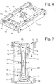
- Fig. 4 shows the cooperating with the coupling mechanism 25 plate unit 40, with the shaft door 13 at each floor 12 is coupled and also mounted vertically.
- the counter element 44 is held by a means, for example a spring, so that it can be adjusted from a rest position upwards or downwards.
- a magnetically formed counter element 44 and a locking member 50 are formed in this plate unit 40.
- This locking member 50 is displaceably mounted perpendicular to the plane of the plate and can be moved from a locked starting position in a against the coupling member 24 out notched position, whereby the plate unit 40 and with it the shaft door 13 can be brought into a fixed or in a released position ,
- This locking member 50 is shown in the locked starting position, in which opening of the shaft door 13 is prevented when the elevator is moving, as expediently a cam 51 in a groove, not shown, or the like, for example, the shaft wall 11 'and in the rail 38' almost free of play intervenes.
- the locking member 50 is guided in a longitudinal groove 53 'of a rail 53 in a base plate 42 of the disk unit 40, wherein this longitudinal groove 53' extends in the adjustment direction of the disk unit.
- an operating device 55 cooperating with the rail 53 which serves for emergency evacuation of persons in the cabin 15.
- an operating device 55 cooperating with the rail 53
- the rail 53 is held with cams in grooves 63 of the base plate 42 transverse to this liftable.
- the shaft doors can be pushed apart by hand, with the outer plates 57 pushed in one direction or the other and thereby
- the shaft door can be opened by means of a key operation and with the assistance of emergency batteries.
- the coupling element of the coupling mechanism and the counter element of the plate unit could be provided by a positive coupling as a driver of the shaft door with the car door.
- a coupling mechanism and a panel unit would be provided for each wing door of the cabin or floor, respectively. It could also be provided for each two locking members.
- the coupling mechanism according to the invention could theoretically also be fastened to the respective floor at the shaft door only, while the plate unit cooperating with the coupling mechanism could be assigned to the sliding cabin door.
- this locking member 50 could be omitted from the disk unit 40 if a lock of the hoistway door would otherwise be released.
- such a device can also be used in a railway station in mountain railways or aerial cableways for opening or closing a railway door or an outer door.
Landscapes
- Elevator Door Apparatuses (AREA)
- Lock And Its Accessories (AREA)
- Power-Operated Mechanisms For Wings (AREA)
Description
- Die Erfindung betrifft Einrichtung vorzugsweise für eine Aufzugsanlage zum Betätigen wenigstens einer Kabinen- bzw. Schachttüre nach dem Oberbegriff des Anspruchs 1.
- Bei einem bekannten Aufzug gemäss der Druckschrift
EP-A-2 297 018 ist eine Aufzugkabine mit horizontal verschiebbaren Kabinentürflügeln und bei den Stockwerken mit entsprechenden Schachttürflügeln in bekannter Weise vorgesehen, wobei diese Türflügel parallel zueinander angeordnet sind. Für das Öffnen und Schliessen der Kabinentürflügel ist ein Türantrieb und ausserdem eine Kopplungseinrichtung vorgesehen, die ein Übertragen der entsprechenden Bewegungen auf den Schachttürflügel umfasst und dazu mindestens ein verschiebbares Mitnehmerelement vorgesehen ist, welches in Kontakt mit einem am Schachttürflügel vorhandenen Gegenelement gebracht wird. Zudem sind dem Kabinentürflügel eine Türverriegelung mit einem Kabinentürriegel und einem Riegelanschlag zugeordnet. Eine Sperrwirkung dieser Türverriegelung ist abhängig von dem Zusammenwirken der Kopplungseinrichtung mit dem Gegenelement. Dies wird durch eine Aufzugsteuerung überwacht, bei der mittels eines vorhandenen Sicherheitsschalters bei der Türverriegelung ein Öffnen des Türflügels unterbunden wird, wenn sich die Aufzugskabine nicht genau auf dem Stockwerksniveau befindet. - Die Bewegung des Kabinentürriegels ist starr mit derjenigen des Mitnehmerelements gekoppelt. Wenn sich das Mitnehmerelement in einer vom Gegenelement des Schachttürflügels distanzierten Durchfahrtsstellung befindet bzw. weiter als bis zu einer definierten Kopplungsstellung bewegt, so blockiert der Kabinentürriegel eine Öffnung des Riegelanschlags und damit des Kabinentürflügels. Hingegen kann letzterer geöffnet werden, wenn das Mitnehmerelement vom Gegenelement in einer definierten Kopplungsstellung gestoppt wird.
- Es sind jeweils zwei Mitnehmerelemente eines Kabinentürflügels zwischen zwei Gegenelementen des Schachttürflügels vorgesehen, wenn sich die Aufzugskabine auf Stockwerksniveau befindet, wobei die Mitnehmerelemente durch eine Feder gegen die Gegenelemente gedrückt werden, bevor eine Öffnung des Kabinentürflügels beginnt.
- In der Druckschrift
WO-A-98/14395 - In der Druckschrift
EP-A-0 829 447 ist eine Vorrichtung zur Mitnahme von Schachttüren bei einem Aufzug offenbart, bei der eine Bewegungsmechanik mit einer Hebelanordnung vorgesehen ist, durch welchen ein Mitnehmer in einer senkrecht zu den Türebenen verlaufenden Richtung verschoben wird. Mittels eines Elektromagneten wird der Mitnehmer mit dem Kupplungsteil in Eingriff gebracht, nachdem die Bewegungsmechanik denselben soweit verstellt hat, bis ein eingestellter Luftspalt zwischen dem Elektromagneten und dem Kupplungsteil erreicht worden ist. - Nachteilig bei diesen Vorrichtungen ist der aufwändige Mechanismus für diese Mitnahme der Türen, bei dem diese Bewegungsmechanik und dieser Elektromagnet vorgesehen sind und damit eine genaue Steuerung sowohl zu der Bewegung bzw. zu der Positionierung der Bewegungsmechanik als auch zu dem Elektromagneten erfolgen muss.
- Ausgehend von solchen bekannten Aufzügen liegt der Erfindung die Aufgabe zugrunde, eine Einrichtung zum Betätigen wenigstens einer Kabinen- bzw. Schachttüre zu schaffen, welche bei Erfüllung all der erforderlichen Funktionen für den Betrieb eines Aufzugs eine platzsparende und sichere Konstruktion bietet.
- Erfindungsgemäss ist diese Aufgabe nach den Merkmalen des Anspruchs 1 gelöst.
- Der Kopplungsmechanismus für die Kabinentür weist erfindungsgemäss ein quer zu der Kabinentüre verstellbares Kopplungselement auf, welches von einer zurückgezogenen Position in eine mit einem Gegenelement der Platteneinheit für die Schachttüre gekuppelte Position bewegbar ist.
- Dieser erfindungsgemässe Aufbau der Einrichtung ermöglicht eine einwandfreie Funktion beim Betrieb einer Aufzuganlage, auch wenn Betriebsstörungen vorliegen. Damit kann ein Öffnen bzw. Schliessen der Kabinen- und der Schachttüre auf einfache Weise bewerkstelligt werden.
- Einer der wesentlichen Vorteile besteht zudem darin, dass mit dem erfindungsgemässen Aufbau der Einrichtung gegenüber den bekannten Aufzügen eine Verminderung des Spaltes zwischen der Kabine und dem Schacht türseitig erzielt werden kann, der von ca. 30 auf 10 mm reduzierbar ist. Damit ist nebst einer optischen Verbesserung auch die Gefahr reduziert, dass schmale Gegenstände, wie Schlüssel, Geld oder dergleichen, kaum mehr durch diesen Spalt in den Liftschacht fallen können.
- Sehr vorteilhaft sind dieses verstellbare Kopplungselement des Kopplungsmechanismus sowie das Gegenelement der Platteneinheit als Magnetplatten ausgebildet, durch welche in der gekuppelten Position eine ausreichende Haftkraft erzeugbar ist. Dadurch kann eine Kopplung sehr effizient und sicher erfolgen und durch dieses Zurückziehen des Kopplungselementes wird kein Platzbedarf bei geschlossenen Türen benötigt.
- Diese erfindungsgemässe Einrichtung eignet sich auch zum Nachrüsten und Modernisieren von bestehenden Aufzugsanlagen. Es können zudem bei älteren oder sehr hohen Bauten die damit verbundenen sich ändernden und hohen Toleranzen zwischen Liftkabine und dem Liftschacht bzw. den Schachtwänden wegen Bauabsenkungen, verändernde Abmessungen etc. problemlos ausgeglichen werden.
- Ausführungsbeispiele sowie weitere Vorteile der Erfindung sind nachfolgend anhand einer Zeichnung näher erläutert. Es zeigt:
- Fig. 1
- einen schematischen teilweisen Längsschnitt einer erfindungsgemässen Aufzugsanlage;
- Fig. 2
- eine perspektivische Ansicht eines erfindungsgemässen Kopplungsmechanismus der Aufzugsanlage in Schliessstellung der Türen, welcher mit der Kabinentüre verbunden ist;
- Fig. 3
- eine perspektivische Ansicht des Kopplungsmechanismus nach
Fig. 2 während dem Öffnen bzw. Schliessen der Türen; - Fig. 4
- eine perspektivische Ansicht einer mit dem Kopplungsmechanismus nach
Fig. 2 zusammenwirkenden Platteneinheit, die mit der Schachttüre verbunden ist; und - Fig. 5
- eine Draufsicht auf die Platteneinheit unter Weglassung eines Gegenelementes zur Ansicht einer Betätigungseinrichtung.
- Bei einer teilweisen dargestellten Aufzugsanlage 10 gemäss
Fig. 1 ist ein Liftschacht 11 und eine in diesem geführte auf- und abbewegbare Kabine 15 angedeutet. Diese auf bekannte Weise durch Seile oder dergleichen gehaltene Kabine kann in dem Liftschacht 11 zu den einzelnen Stockwerken 12 durch eine entsprechende Steuerung geführt werden. - Solche Aufzugsanlagen werden allem voran in Häusern, Bürogebäuden, in gewerblichen Gebäuden oder dergleichen installiert und sie dienen für die Beförderung von Personen, Tieren und/oder Gegenständen aller Art. Sie eignet sich speziell auch für Aufzugsanlagen, die mit zumindest teilweise in horizontaler Richtung verlaufenden Schächten gebaut sind.
- Sowohl bei der Kabine 15 als auch bei den jeweiligen Stockwerken 12 sind je wenigstens eine Kabinentüre 16 und eine Schachttüre 13 vorgesehen, die quer zur Bildebene geöffnet bzw. geschlossen werden können. Je nach Platzverhältnissen können auch zwei oder mehr solcher Türen pro Kabine und pro Stockwerk installiert sein. Den Türen 13, 16 sind auf ihrer Oberseite Rollen 14, 38 zugeordnet, die via Verbindungselemente 21, 39 an fest installierten Führungsschienen 14', 38' einerseits an der Kabine 15 und andererseits in der Schachtwandung 11' geführt sind. An der Unterseite sind diese Türen 13, 16 vorteilhaft in Längsführungen 13', 16' geführt.
- Eine Einrichtung 20 zum Betätigen der Kabinen- bzw. Schachttüre 13, 16 ist vorteilhaft auf der Oberseite der Kabine 15 platziert. Es ist ein von einer Steuerung betätigbarer Antriebsmotor 17 auf der KabinenOberseite angeordnet, welcher üblicherweise einen umlaufenden Zahnriemen als Antriebselement 18 für die Türen 13, 16 antreibt.
-
Fig. 2 und Fig. 3 zeigen einen Kopplungsmechanismus 25 der Einrichtung 20, welcher an der verschiebbaren Kabinentüre 16 befestigbar ist und im montierten Zustand, wie inFig. 1 ersichtlich ist, in vertikaler Ausrichtung angeordnet ist. Die teilweise gezeigte Führungsschiene 14' ist beim Antriebsmotor 17 in ihrer Längserstreckung horizontal verlaufend befestigt und die inFig. 1 angedeuteten Rollen 14 sind bei einer an der Kabinentüre 16 befestigbaren Grundplatte 21 drehbar gelagert. - Erfindungsgemäss weist der Kopplungsmechanismus 25 ein quer zu diesem bzw. zu der Kabinentüre 16 verstellbares Kopplungselement 24 auf, welches von einer zurückgezogenen Position, wie in
Fig. 2 ersichtlich ist, in eine mit einem Gegenelement der Platteneinheit 40 gekuppelte Position, wie inFig. 3 dargestellt ist, bewegbar ist. - Sehr vorteilhaft sind das verstellbare Kopplungselement 24 des Kopplungsmechanismus 25 sowie das Gegenelement 44 der Platteneinheit 40 jeweils als Magnetplatte ausgebildet, durch welche in der gekuppelten Position eine ausreichende Haftkraft erzeugbar ist, welche noch durch nicht gezeigte Druckfedern unterstützt werden kann. Das Kopplungselement 24 besteht dabei aus einem oder mehreren Magneten. Damit lässt sich eine schnelle und wirksame Kupplung zwischen Kabinen- und Schachttüre herbeiführen.
- Gemäss
Fig. 2 und Fig. 3 umfasst der Kopplungsmechanismus 25 eine Verstelleinrichtung 26 für das Kopplungselement 24, eine mit dem Antriebselement 18 des Türantriebs durch eine Klemme 31 verbindbare Wippe 22 sowie ein schwenkbares Übertragungsglied 23, welche an der Grundplatte 21 angeordnet sind. Die Verstelleinrichtung 26 ist mit einem Schlitten 27 mit wenigstens einer, vorliegend zwei Führungsstangen 28 und mit einem an letzteren angelenktes Schwenkelement 29 für das quere Verstellen des senkrecht in der Grundplatte 21 gelagerten Kopplungselementes 24 versehen, wobei der längsbewegbare Schlitten 27 mit dem drehbar gelagerten Übertragungsglied 23 gekoppelt ist. - Wenn nun durch die Aufzugssteuerung die Türen geöffnet werden sollen, so wird ausgehend von der Stellung des Kopplungsmechanismus 25 gemäss
Fig. 2 durch ein von der Liftsteuerung bewirktes Auslösen diese mit einem Anschlagbolzen 22' zusammenwirkende Wippe 22 von einem Zugelement 19 um einen bestimmten Winkel geschwenkt und damit ein Koppeln der Klemme 31 mit dem Zahnriemen 18 bewirkt. Gleichsam wird das Übertragungsglied 23 um eine Schwenkachse 23' eines an der Grundplatte 21 gelenkig gelagerten Hebels 32 gedreht und die Verstelleinrichtung 26 betätigt, so dass das Schwenkelement 29 diese Querbewegung des Kopplungselementes 24 auslöst, bis dasselbe gemäss der Position nachFig. 3 mit dem Gegenelement 44 verbunden ist. Nach dem Schliessen der Türen wird das Kopplungselement 24 wieder in umgekehrter Richtung in die Position gemässFig. 2 gebracht. -
Fig. 4 zeigt die mit dem Kopplungsmechanismus 25 zusammenwirkende Platteneinheit 40, die mit der Schachttüre 13 beim jeweiligen Stockwerk 12 gekoppelt und ebenfalls vertikal montiert ist. Es ist dabei eine rückseitig mit der Schachttüre 13 verbindbare Abdeckplatte 54 und das mit dieser via seitliche Gleitführungen 56 in der Höhe verstellbare Gegenelement 44 vorgesehen. Zweckmässigerweise ist das Gegenelement 44 durch ein Mittel, zum Beispiel eine Feder, so gehalten, dass es sich von einer Ruheposition nach oben bzw. nach unten verstellen kann. - Damit wird als weiterer Vorteil der Erfindung erreicht, dass nach einer Kopplung des Kopplungselementes 24 mit dem Gegenelement 44 allfällige Höhenveränderungen der Kabine 15 beim Ein- bzw. Aussteigen von Personen bzw. beim Be- bzw. Entladen ausgeglichen werden, indem sich dieses Gegenelement mit dem Kopplungselement und der Kabine leicht nach unten oder nach oben bewegen kann.
- Im Rahmen der Erfindung ist in dieser Platteneinheit 40 ein magnetisch ausgebildetes Gegenelement 44 sowie ein Verriegelungsorgan 50 ausgebildet. Dieses Verriegelungsorgan 50 ist dabei senkrecht zu der Plattenebene verschiebbar gelagert und kann von einer verriegelten Ausgangsstellung in eine gegen das Kopplungselement 24 hin ausgerastete Stellung bewegt werden, wodurch die Platteneinheit 40 und mit ihr die Schachttüre 13 in eine fixierte oder in eine gelöste Position gebracht werden kann.
- Mit diesen Neuerungen der erfindungsgemässen Einrichtung kann auch eine vorzeitige Türöffnung der Lift- bzw. Schachttüren im Gegensatz zu den bekannten Einrichtungen vermieden werden.
- In der gezeigten Stellung der Rückseite der Platteneinheit 40 gemäss
Fig. 4 ist dieses Verriegelungsorgan 50 in der verriegelten Ausgangsstellung dargestellt, bei der ein Öffnen der Schachttüre 13 bei fahrendem Aufzug verhindert wird, da zweckmässigerweise ein Nocken 51 in eine nicht gezeigte Nut oder dergleichen beispielsweise bei der Schachtwand 11' bzw. in der Schiene 38' annähernd spielfrei eingreift. Das Verriegelungsorgan 50 ist in einer Längsnut 53' einer Schiene 53 in einer Basisplatte 42 der Platteneinheit 40 geführt, wobei sich diese Längsnut 53' in Verstellrichtung der Platteneinheit erstreckt. - Gemäss
Fig. 5 ist eine mit der Schiene 53 zusammenwirkende Betätigungseinrichtung 55 vorgesehen, die für ein Notevakuieren von Personen in der Kabine 15 dient. Durch eine Querverstellung von Aussenplatten 57 und Hebeln 58 quer zur Längserstreckung der Schiene 53 wird letztere und mit ihr das Verriegelungsorgan 50 angehoben und damit eine Entriegelung des Verriegelungsorgans bewirkt. Es sind entsprechend ausgebildete Kipphebel 59 einerseits mit den Hebeln 58 und andererseits an Achsen 52 gelenkig verbunden und andererseits durch an diesen Kipphebeln 59 angeordnete Schrägflächen 59' mit der Schiene 53 in Wirkverbindung, derart, dass die Schiene und mit ihr das Verriegelungsorgan 50 beim Verschwenken der Kipphebel 59 angehoben werden. Die Schiene 53 ist dabei mit Nocken in Nuten 63 der Basisplatte 42 quer zu dieser anhebbar gehalten. - In einer Notsituation, wie beispielsweise bei einem Stromausfall, können die Schachttüren von Hand auseinandergedrückt werden, wobei die Aussenplatten 57 in die eine oder andere Richtung geschoben und dadurch diesem Zwecke kann die Schachttüre mittels Schlüsselbetätigung und mit Unterstützung von Notstrombatterien geöffnet werden.
- Die Erfindung ist mit den oben erläuterten Ausführungsbeispielen ausreichend dargetan. Sie könnte aber selbstverständlich noch durch andere Varianten verdeutlicht sein. So könnten beispielsweise das Kopplungselement des Kopplungsmechanismus sowie das Gegenelement der Platteneinheit durch eine formschlüssige Kupplung als Mitnehmer der Schachttüre mit der Kabinentüre vorgesehen sein.
- Wenn zwei oder mehr solcher Türen für eine Kabine und für ein Stockwerk vorgesehen wären, wie dies bei der eingangs erwähnten Druckschrift veranschaulicht ist, so würden für jede Flügeltüre der Kabine bzw. des Stockwerks jeweils ein Kopplungsmechanismus und eine Platteneinheit vorgesehen sein. Dabei könnten auch je zwei Verriegelungsorgane vorgesehen sein.
- Der erfindungsgemässe Kopplungsmechanismus könnte theoretisch auch bzw. nur bei Schachttüre beim jeweiligen Stockwerk befestigt sein, währenddem die mit dem Kopplungsmechanismus zusammenwirkende Platteneinheit der verschiebbaren Kabinentüre zugeordnet sein könnte.
- Theoretisch könnte dieses Verriegelungsorgan 50 bei der Platteneinheit 40 weggelassen sein, wenn eine Verriegelung der Schachttüre anderweitig gelöst würde.
- Im Prinzip kann eine solche Einrichtung auch in einer Bahnstation bei Bergbahnen bzw. Luftseilbahnen zum Öffnen bzw. Schliessen einer Bahntüre bzw. einer Aussentüre eingesetzt werden.
Claims (10)
- Einrichtung vorzugsweise für eine Aufzugsanlage zum Betätigen wenigstens einer Kabinen- bzw. Schachttüre (13, 16), mit einem Kopplungsmechanismus (25), welcher an einer verschiebbaren Kabinentüre (16) einer Kabine (15) und/oder an einer Schachttüre (13) beim jeweiligen Stockwerk (12) befestigbar ist, bzw. mit einer mit dem Kopplungsmechanismus (25) zusammenwirkenden Platteneinheit (40), die an der Schachttüre (13) beim jeweiligen Stockwerk (12) oder an der Kabinentüre (16) fixierbar ist, wobei der Kopplungsmechanismus (25) ein quer zu diesem bzw. zu der Kabinentüre (16) bzw. Schachttüre (13) verstellbares Kopplungselement (24) aufweist, welches von einer zurückgezogenen Position in eine mit einem Gegenelement (44) der Platteneinheit (40) gekuppelte Position bewegbar ist, dadurch gekennzeichnet, dass das Kopplungselement (24) einer Verstelleinrichtung (26) des Kopplungsmechanismus (25) von der zurückgezogenen Position in die mit dem Gegenelement (44) der Platteneinheit (40) gekuppelten Position bewegbar ist.
- Einrichtung nach Anspruch 1, dadurch gekennzeichnet, dass das verstellbare Kopplungselement (24) des Kopplungsmechanismus (25) sowie das Gegenelement der Platteneinheit (40) jeweils magnetisch ausgebildet sind, durch welche in der gekuppelten Position eine ausreichende magnetische Haftkraft zwischen diesen erzeugbar ist.
- Einrichtung nach Anspruch 1 oder 2, dadurch gekennzeichnet, dass der Kopplungsmechanismus (25) eine an der Kabinentüre (16) befestigbare Grundplatte (21) oder dergleichen, ein mit einem Antriebselement (18) herstellbare Verbindung und der Verstelleinrichtung (26) für das Kopplungselement (24) umfasst.
- Einrichtung nach Anspruch 3, dadurch gekennzeichnet, dass eine mit einem Antriebselement (18) des Türantriebs verbundene Wippe (22) als Verbindung sowie ein Übertragungsglied (23) von der Wippe zu der Verstelleinrichtung vorgesehen ist.
- Einrichtung nach Anspruch 3 oder 4, dadurch gekennzeichnet, dass die auf der Grundplatte (21) montierte Verstelleinrichtung (26) mit einem Schlitten (27) mit wenigstens einer Führungsstange (28) und mit einem an letzteren angelenktes Schwenkelement (29) für das quere Verstellen des senkrecht in der Grundplatte gelagerten Kopplungselementes (24) versehen ist, wobei der Schlitten (27) quer dazu mit dem drehbar gelagerten Übertragungsglied (23) bewegbar ist.
- Einrichtung nach Anspruch 1 oder 2, dadurch gekennzeichnet, dass die Platteneinheit (40) eine rückseitig mit der Schachttüre (13) verbindbare Abdeckplatte (54) und das mit letzterer via Gleitführungen (56) in der Höhe verstellbare Gegenelement (44) aufweist.
- Einrichtung nach einem der vorhergehenden Ansprüche 1 bis 6, dadurch gekennzeichnet, dass die Platteneinheit (40) wenigstens ein Verriegelungsorgan (50) als Gegenelement aufweist, welches in Querrichtung zu der Plattenebene von einer verriegelten Ausgangsstellung in eine gegen das Kopplungselement (24) hin entriegelte Stellung verschiebbar angeordnet und damit die Platteneinheit (40) und die mit ihr verbundene Schachttüre (13) in eine fixierte oder in eine gelöste Position bringbar ist.
- Einrichtung nach Anspruch 7, dadurch gekennzeichnet, dass das Verriegelungsorgan (50) in einer Längsnut (53') einer Schiene (53) in der Platteneinheit (40) geführt ist, wobei sich diese Längsnut in Verstellrichtung der Platteneinheit erstreckt.
- Einrichtung nach Anspruch 7 oder 8, dadurch gekennzeichnet, dass die Schiene (53) durch eine Betätigungseinrichtung (55) senkrecht zu Ihrer Längserstreckung verschiebbar ist, um ein Entriegeln des Verriegelungsorgans und damit ein Bewegen der Platteneinheit (40) zu bewirken.
- Einrichtung nach Anspruch 9, dadurch gekennzeichnet, dass die Betätigungseinrichtung (55) von aussen verschiebbare Hebel (58), mit diesen gelenkig verbundene Kipphebel (59) und an letzteren angeordnete Schrägflächen (59') aufweist, wobei diese Schrägflächen (59') mit der Schiene (53) in Wirkverbindung stehen, derart, dass die Schiene und mit ihr das Verriegelungsorgan (50) beim Verschwenken der Kipphebel (59) durch die Hebel (58) angehoben wird.
Priority Applications (2)
| Application Number | Priority Date | Filing Date | Title |
|---|---|---|---|
| SI201531027T SI3186183T1 (sl) | 2014-08-25 | 2015-08-21 | Priprava za aktiviranje vrat kabine in jaška dvigalne naprave |
| PL15753370T PL3186183T3 (pl) | 2014-08-25 | 2015-08-21 | Urządzenie do uruchamiania drzwi kabiny i szybu instalacji dźwigowej |
Applications Claiming Priority (2)
| Application Number | Priority Date | Filing Date | Title |
|---|---|---|---|
| CH01300/14A CH710032B1 (de) | 2014-08-25 | 2014-08-25 | Einrichtung für eine Aufzugsanlage zum Betätigen wenigstens einer Kabinen- bzw. Schachttüre. |
| PCT/EP2015/069253 WO2016030296A1 (de) | 2014-08-25 | 2015-08-21 | Einrichtung zum betätigen einer kabinen- und schachttür einer aufzugsanlage |
Publications (2)
| Publication Number | Publication Date |
|---|---|
| EP3186183A1 EP3186183A1 (de) | 2017-07-05 |
| EP3186183B1 true EP3186183B1 (de) | 2019-09-11 |
Family
ID=53900829
Family Applications (1)
| Application Number | Title | Priority Date | Filing Date |
|---|---|---|---|
| EP15753370.4A Active EP3186183B1 (de) | 2014-08-25 | 2015-08-21 | Einrichtung zum betätigen einer kabinen- und schachttür einer aufzugsanlage |
Country Status (12)
| Country | Link |
|---|---|
| US (2) | US10392229B2 (de) |
| EP (1) | EP3186183B1 (de) |
| CN (1) | CN107074501B (de) |
| AR (1) | AR101681A1 (de) |
| CH (1) | CH710032B1 (de) |
| ES (1) | ES2761642T3 (de) |
| HU (1) | HUE047718T2 (de) |
| PL (1) | PL3186183T3 (de) |
| PT (1) | PT3186183T (de) |
| SI (1) | SI3186183T1 (de) |
| TW (1) | TWI673227B (de) |
| WO (1) | WO2016030296A1 (de) |
Families Citing this family (7)
| Publication number | Priority date | Publication date | Assignee | Title |
|---|---|---|---|---|
| CH710032B1 (de) | 2014-08-25 | 2018-04-13 | Salvenmoser Michael | Einrichtung für eine Aufzugsanlage zum Betätigen wenigstens einer Kabinen- bzw. Schachttüre. |
| DE102017111560A1 (de) * | 2017-05-26 | 2018-11-29 | Thyssenkrupp Ag | Fahrkorb für eine Aufzugsanlage und Verfahren zum Öffnen und Schließen einer Türöffnung |
| CN109956386B (zh) * | 2017-12-14 | 2024-04-09 | 湖南捷达电梯工程有限公司 | 一种电梯门机系统 |
| CN109281587B (zh) * | 2018-10-29 | 2023-10-20 | 上海东铁五金有限公司 | 带防脱功能的平移式紧急疏散自动门 |
| JP6810916B1 (ja) * | 2020-03-03 | 2021-01-13 | フジテック株式会社 | ドア用係合装置 |
| CN112061937A (zh) * | 2020-09-24 | 2020-12-11 | 中国五冶集团有限公司 | 一种施工电梯 |
| US12297078B2 (en) * | 2023-07-10 | 2025-05-13 | Otis Elevator Company | Magnetic door coupler |
Family Cites Families (17)
| Publication number | Priority date | Publication date | Assignee | Title |
|---|---|---|---|---|
| US2481124A (en) * | 1944-09-13 | 1949-09-06 | Express Lift Co Ltd | Door-operating mechanism for lift doors and the like |
| GB712722A (en) | 1952-06-03 | 1954-07-28 | Wm Wadsworth & Sons Ltd | Improvements relating to the doors of lifts |
| US3033317A (en) | 1956-10-25 | 1962-05-08 | Montgomery Elevator | Mechanism for operating an elevator hatch door and interlock |
| US2996152A (en) | 1960-04-06 | 1961-08-15 | Olexson George | Magnetic retractable door roller for automatic elevators |
| JPS538973B2 (de) | 1972-07-25 | 1978-04-03 | ||
| JPH05162956A (ja) | 1991-12-12 | 1993-06-29 | Toshiba Corp | エレベータドア装置 |
| US5487449A (en) * | 1994-04-06 | 1996-01-30 | Otis Elevator Company | Magnetic elevator door coupling |
| US5896952A (en) * | 1996-08-22 | 1999-04-27 | Inventio Ag | Apparatus for coupling elevator doors |
| ATE256076T1 (de) * | 1996-09-17 | 2003-12-15 | Inventio Ag | Vorrichtung zur mitnahme von schachttüren bei aufzügen |
| TR199900743T2 (xx) | 1996-10-03 | 1999-09-21 | Inventio Ag | Asans�r kap�lar�n� �al��t�rma sistemi. |
| US6070700A (en) * | 1997-09-16 | 2000-06-06 | Inventio Ag | Operating system for elevator doors |
| GB2461452B (en) | 2007-03-23 | 2011-10-26 | Otis Elevator Co | Electromagnetic coupling with a slider layer |
| EP2138442A1 (de) * | 2008-06-25 | 2009-12-30 | Inventio Ag | Aufzugtürsystem mit Kabinentürverriegelung |
| US8746412B2 (en) | 2008-12-19 | 2014-06-10 | Otis Elevator Company | Elevator door frame with electronics housing |
| CN201990356U (zh) * | 2011-02-15 | 2011-09-28 | 苏州莱茵电梯制造有限公司 | 一种应用于电梯上的动力层门系统 |
| DE202014102534U1 (de) * | 2014-05-13 | 2015-08-18 | Wittur Holding Gmbh | Türkuppler mit flexibel positionierbaren Kupplerkufen |
| CH710032B1 (de) | 2014-08-25 | 2018-04-13 | Salvenmoser Michael | Einrichtung für eine Aufzugsanlage zum Betätigen wenigstens einer Kabinen- bzw. Schachttüre. |
-
2014
- 2014-08-25 CH CH01300/14A patent/CH710032B1/de unknown
-
2015
- 2015-08-21 PL PL15753370T patent/PL3186183T3/pl unknown
- 2015-08-21 SI SI201531027T patent/SI3186183T1/sl unknown
- 2015-08-21 PT PT157533704T patent/PT3186183T/pt unknown
- 2015-08-21 ES ES15753370T patent/ES2761642T3/es active Active
- 2015-08-21 EP EP15753370.4A patent/EP3186183B1/de active Active
- 2015-08-21 US US15/506,283 patent/US10392229B2/en active Active
- 2015-08-21 HU HUE15753370A patent/HUE047718T2/hu unknown
- 2015-08-21 WO PCT/EP2015/069253 patent/WO2016030296A1/de not_active Ceased
- 2015-08-21 CN CN201580045698.1A patent/CN107074501B/zh active Active
- 2015-08-24 TW TW104127494A patent/TWI673227B/zh active
- 2015-08-24 AR ARP150102714A patent/AR101681A1/es active IP Right Grant
-
2019
- 2019-08-26 US US16/551,173 patent/US11192755B2/en active Active
Non-Patent Citations (1)
| Title |
|---|
| None * |
Also Published As
| Publication number | Publication date |
|---|---|
| AR101681A1 (es) | 2017-01-04 |
| TW201620812A (zh) | 2016-06-16 |
| CN107074501A (zh) | 2017-08-18 |
| HUE047718T2 (hu) | 2020-05-28 |
| PT3186183T (pt) | 2019-12-18 |
| US20200010303A1 (en) | 2020-01-09 |
| PL3186183T3 (pl) | 2020-04-30 |
| CN107074501B (zh) | 2019-12-03 |
| US10392229B2 (en) | 2019-08-27 |
| CH710032A2 (de) | 2016-02-29 |
| TWI673227B (zh) | 2019-10-01 |
| ES2761642T3 (es) | 2020-05-20 |
| US11192755B2 (en) | 2021-12-07 |
| CH710032B1 (de) | 2018-04-13 |
| US20170267494A1 (en) | 2017-09-21 |
| EP3186183A1 (de) | 2017-07-05 |
| WO2016030296A1 (de) | 2016-03-03 |
| SI3186183T1 (sl) | 2020-02-28 |
Similar Documents
| Publication | Publication Date | Title |
|---|---|---|
| EP3186183B1 (de) | Einrichtung zum betätigen einer kabinen- und schachttür einer aufzugsanlage | |
| DE2164980C2 (de) | Türantriebsvorrichtung mit Verriegelungsmechanismus für Aufzüge | |
| EP0332841B1 (de) | Türantriebsvorrichtung mit Verriegelungsmechanismus für Aufzüge | |
| EP0513509B1 (de) | Aufzug | |
| EP1713712B9 (de) | Vorrichtung zur betätigung und verriegelung von aufzugstüren | |
| EP1541518B1 (de) | Aufzugs-Türantriebsvorrichtung | |
| DE602004012327T2 (de) | Mitnehmer für aufzugskabine- und schachttüren | |
| EP1820767A1 (de) | Verfahren zur Modernisierung des Kabinentürsystems eines Aufzugs und Modernisierungsbausatz zur Durchführung des Verfahrens | |
| EP3243984A1 (de) | Türschlossvorrichtung für eine paniktür | |
| EP2709941B1 (de) | Aufzugsystem | |
| EP1794399B1 (de) | Bodenverriegelung | |
| EP0839753A1 (de) | Vorrichtung zum Öffnen und Schliessen einer Kabinentür und einer Schachttür einer Aufzugsanlage | |
| EP4547591B1 (de) | Aufzug | |
| DE19900875C2 (de) | Verriegelungsvorrichtung für eine Türanlage | |
| DE69803021T2 (de) | Motorbetriebene Verriegelungsvorrichtung eines Türflügels, Tür mit solch einer Vorrichtung und damit ausgerüstetes Schienenfahrzeug | |
| EP0929495A1 (de) | Mitnehmersystem für aufzugstüren | |
| EP0829446A1 (de) | Mitnehmeeinrichtung für Aufzugstüren | |
| EP0912811B1 (de) | Schiebetür | |
| EP2695843A1 (de) | Türkuppler mit Entlastung des Schachttürriegels | |
| EP4587362B1 (de) | Türantriebsvorrichtung mit zwei unabhängigen voneinander verlagerbaren mitnehmer | |
| EP1801337B1 (de) | Vorrichtung zur Schließfolgeregelung für zweiflügelige Drehtüren | |
| DE60032698T2 (de) | Vorrichtung zum Öffnen und Schliessen von Aufzugstürflügeln | |
| EP2072449A1 (de) | Türantriebsvorrichtung für Aufzugsanlagen | |
| EP4594235A1 (de) | Türsystem | |
| DE102025104474A1 (de) | Bremsvorrichtung für einen Fahrkorb einer Aufzugsanlage |
Legal Events
| Date | Code | Title | Description |
|---|---|---|---|
| STAA | Information on the status of an ep patent application or granted ep patent |
Free format text: STATUS: THE INTERNATIONAL PUBLICATION HAS BEEN MADE |
|
| PUAI | Public reference made under article 153(3) epc to a published international application that has entered the european phase |
Free format text: ORIGINAL CODE: 0009012 |
|
| STAA | Information on the status of an ep patent application or granted ep patent |
Free format text: STATUS: REQUEST FOR EXAMINATION WAS MADE |
|
| 17P | Request for examination filed |
Effective date: 20170201 |
|
| AK | Designated contracting states |
Kind code of ref document: A1 Designated state(s): AL AT BE BG CH CY CZ DE DK EE ES FI FR GB GR HR HU IE IS IT LI LT LU LV MC MK MT NL NO PL PT RO RS SE SI SK SM TR |
|
| AX | Request for extension of the european patent |
Extension state: BA ME |
|
| DAV | Request for validation of the european patent (deleted) | ||
| DAX | Request for extension of the european patent (deleted) | ||
| STAA | Information on the status of an ep patent application or granted ep patent |
Free format text: STATUS: EXAMINATION IS IN PROGRESS |
|
| 17Q | First examination report despatched |
Effective date: 20181109 |
|
| GRAJ | Information related to disapproval of communication of intention to grant by the applicant or resumption of examination proceedings by the epo deleted |
Free format text: ORIGINAL CODE: EPIDOSDIGR1 |
|
| GRAP | Despatch of communication of intention to grant a patent |
Free format text: ORIGINAL CODE: EPIDOSNIGR1 |
|
| GRAP | Despatch of communication of intention to grant a patent |
Free format text: ORIGINAL CODE: EPIDOSNIGR1 |
|
| STAA | Information on the status of an ep patent application or granted ep patent |
Free format text: STATUS: GRANT OF PATENT IS INTENDED |
|
| GRAS | Grant fee paid |
Free format text: ORIGINAL CODE: EPIDOSNIGR3 |
|
| INTG | Intention to grant announced |
Effective date: 20190621 |
|
| INTG | Intention to grant announced |
Effective date: 20190628 |
|
| GRAA | (expected) grant |
Free format text: ORIGINAL CODE: 0009210 |
|
| STAA | Information on the status of an ep patent application or granted ep patent |
Free format text: STATUS: THE PATENT HAS BEEN GRANTED |
|
| AK | Designated contracting states |
Kind code of ref document: B1 Designated state(s): AL AT BE BG CH CY CZ DE DK EE ES FI FR GB GR HR HU IE IS IT LI LT LU LV MC MK MT NL NO PL PT RO RS SE SI SK SM TR |
|
| REG | Reference to a national code |
Ref country code: GB Ref legal event code: FG4D Free format text: NOT ENGLISH |
|
| REG | Reference to a national code |
Ref country code: CH Ref legal event code: EP |
|
| REG | Reference to a national code |
Ref country code: AT Ref legal event code: REF Ref document number: 1178226 Country of ref document: AT Kind code of ref document: T Effective date: 20190915 |
|
| REG | Reference to a national code |
Ref country code: DE Ref legal event code: R096 Ref document number: 502015010348 Country of ref document: DE Ref country code: IE Ref legal event code: FG4D Free format text: LANGUAGE OF EP DOCUMENT: GERMAN |
|
| REG | Reference to a national code |
Ref country code: RO Ref legal event code: EPE |
|
| REG | Reference to a national code |
Ref country code: PT Ref legal event code: SC4A Ref document number: 3186183 Country of ref document: PT Date of ref document: 20191218 Kind code of ref document: T Free format text: AVAILABILITY OF NATIONAL TRANSLATION Effective date: 20191209 |
|
| REG | Reference to a national code |
Ref country code: CH Ref legal event code: NV Representative=s name: LUCHS AND PARTNER AG PATENTANWAELTE, CH |
|
| REG | Reference to a national code |
Ref country code: SE Ref legal event code: TRGR |
|
| REG | Reference to a national code |
Ref country code: NL Ref legal event code: FP |
|
| REG | Reference to a national code |
Ref country code: LT Ref legal event code: MG4D |
|
| PG25 | Lapsed in a contracting state [announced via postgrant information from national office to epo] |
Ref country code: BG Free format text: LAPSE BECAUSE OF FAILURE TO SUBMIT A TRANSLATION OF THE DESCRIPTION OR TO PAY THE FEE WITHIN THE PRESCRIBED TIME-LIMIT Effective date: 20191211 Ref country code: NO Free format text: LAPSE BECAUSE OF FAILURE TO SUBMIT A TRANSLATION OF THE DESCRIPTION OR TO PAY THE FEE WITHIN THE PRESCRIBED TIME-LIMIT Effective date: 20191211 Ref country code: HR Free format text: LAPSE BECAUSE OF FAILURE TO SUBMIT A TRANSLATION OF THE DESCRIPTION OR TO PAY THE FEE WITHIN THE PRESCRIBED TIME-LIMIT Effective date: 20190911 Ref country code: LT Free format text: LAPSE BECAUSE OF FAILURE TO SUBMIT A TRANSLATION OF THE DESCRIPTION OR TO PAY THE FEE WITHIN THE PRESCRIBED TIME-LIMIT Effective date: 20190911 |
|
| PG25 | Lapsed in a contracting state [announced via postgrant information from national office to epo] |
Ref country code: GR Free format text: LAPSE BECAUSE OF FAILURE TO SUBMIT A TRANSLATION OF THE DESCRIPTION OR TO PAY THE FEE WITHIN THE PRESCRIBED TIME-LIMIT Effective date: 20191212 Ref country code: RS Free format text: LAPSE BECAUSE OF FAILURE TO SUBMIT A TRANSLATION OF THE DESCRIPTION OR TO PAY THE FEE WITHIN THE PRESCRIBED TIME-LIMIT Effective date: 20190911 Ref country code: AL Free format text: LAPSE BECAUSE OF FAILURE TO SUBMIT A TRANSLATION OF THE DESCRIPTION OR TO PAY THE FEE WITHIN THE PRESCRIBED TIME-LIMIT Effective date: 20190911 Ref country code: LV Free format text: LAPSE BECAUSE OF FAILURE TO SUBMIT A TRANSLATION OF THE DESCRIPTION OR TO PAY THE FEE WITHIN THE PRESCRIBED TIME-LIMIT Effective date: 20190911 |
|
| PG25 | Lapsed in a contracting state [announced via postgrant information from national office to epo] |
Ref country code: EE Free format text: LAPSE BECAUSE OF FAILURE TO SUBMIT A TRANSLATION OF THE DESCRIPTION OR TO PAY THE FEE WITHIN THE PRESCRIBED TIME-LIMIT Effective date: 20190911 |
|
| REG | Reference to a national code |
Ref country code: ES Ref legal event code: FG2A Ref document number: 2761642 Country of ref document: ES Kind code of ref document: T3 Effective date: 20200520 |
|
| REG | Reference to a national code |
Ref country code: HU Ref legal event code: AG4A Ref document number: E047718 Country of ref document: HU |
|
| PG25 | Lapsed in a contracting state [announced via postgrant information from national office to epo] |
Ref country code: CZ Free format text: LAPSE BECAUSE OF FAILURE TO SUBMIT A TRANSLATION OF THE DESCRIPTION OR TO PAY THE FEE WITHIN THE PRESCRIBED TIME-LIMIT Effective date: 20190911 Ref country code: IS Free format text: LAPSE BECAUSE OF FAILURE TO SUBMIT A TRANSLATION OF THE DESCRIPTION OR TO PAY THE FEE WITHIN THE PRESCRIBED TIME-LIMIT Effective date: 20200224 Ref country code: SM Free format text: LAPSE BECAUSE OF FAILURE TO SUBMIT A TRANSLATION OF THE DESCRIPTION OR TO PAY THE FEE WITHIN THE PRESCRIBED TIME-LIMIT Effective date: 20190911 Ref country code: SK Free format text: LAPSE BECAUSE OF FAILURE TO SUBMIT A TRANSLATION OF THE DESCRIPTION OR TO PAY THE FEE WITHIN THE PRESCRIBED TIME-LIMIT Effective date: 20190911 |
|
| REG | Reference to a national code |
Ref country code: DE Ref legal event code: R097 Ref document number: 502015010348 Country of ref document: DE |
|
| PLBE | No opposition filed within time limit |
Free format text: ORIGINAL CODE: 0009261 |
|
| STAA | Information on the status of an ep patent application or granted ep patent |
Free format text: STATUS: NO OPPOSITION FILED WITHIN TIME LIMIT |
|
| PG2D | Information on lapse in contracting state deleted |
Ref country code: IS |
|
| PG25 | Lapsed in a contracting state [announced via postgrant information from national office to epo] |
Ref country code: IS Free format text: LAPSE BECAUSE OF FAILURE TO SUBMIT A TRANSLATION OF THE DESCRIPTION OR TO PAY THE FEE WITHIN THE PRESCRIBED TIME-LIMIT Effective date: 20200112 Ref country code: DK Free format text: LAPSE BECAUSE OF FAILURE TO SUBMIT A TRANSLATION OF THE DESCRIPTION OR TO PAY THE FEE WITHIN THE PRESCRIBED TIME-LIMIT Effective date: 20190911 |
|
| 26N | No opposition filed |
Effective date: 20200615 |
|
| PG25 | Lapsed in a contracting state [announced via postgrant information from national office to epo] |
Ref country code: MC Free format text: LAPSE BECAUSE OF FAILURE TO SUBMIT A TRANSLATION OF THE DESCRIPTION OR TO PAY THE FEE WITHIN THE PRESCRIBED TIME-LIMIT Effective date: 20190911 |
|
| PG25 | Lapsed in a contracting state [announced via postgrant information from national office to epo] |
Ref country code: LU Free format text: LAPSE BECAUSE OF NON-PAYMENT OF DUE FEES Effective date: 20200821 |
|
| PG25 | Lapsed in a contracting state [announced via postgrant information from national office to epo] |
Ref country code: IE Free format text: LAPSE BECAUSE OF NON-PAYMENT OF DUE FEES Effective date: 20200821 |
|
| PG25 | Lapsed in a contracting state [announced via postgrant information from national office to epo] |
Ref country code: MT Free format text: LAPSE BECAUSE OF FAILURE TO SUBMIT A TRANSLATION OF THE DESCRIPTION OR TO PAY THE FEE WITHIN THE PRESCRIBED TIME-LIMIT Effective date: 20190911 Ref country code: CY Free format text: LAPSE BECAUSE OF FAILURE TO SUBMIT A TRANSLATION OF THE DESCRIPTION OR TO PAY THE FEE WITHIN THE PRESCRIBED TIME-LIMIT Effective date: 20190911 |
|
| PG25 | Lapsed in a contracting state [announced via postgrant information from national office to epo] |
Ref country code: MK Free format text: LAPSE BECAUSE OF FAILURE TO SUBMIT A TRANSLATION OF THE DESCRIPTION OR TO PAY THE FEE WITHIN THE PRESCRIBED TIME-LIMIT Effective date: 20190911 |
|
| PGFP | Annual fee paid to national office [announced via postgrant information from national office to epo] |
Ref country code: NL Payment date: 20250821 Year of fee payment: 11 |
|
| PGFP | Annual fee paid to national office [announced via postgrant information from national office to epo] |
Ref country code: HU Payment date: 20250814 Year of fee payment: 11 |
|
| PGFP | Annual fee paid to national office [announced via postgrant information from national office to epo] |
Ref country code: ES Payment date: 20250917 Year of fee payment: 11 Ref country code: PT Payment date: 20250813 Year of fee payment: 11 Ref country code: FI Payment date: 20250820 Year of fee payment: 11 |
|
| PGFP | Annual fee paid to national office [announced via postgrant information from national office to epo] |
Ref country code: DE Payment date: 20250912 Year of fee payment: 11 |
|
| PGFP | Annual fee paid to national office [announced via postgrant information from national office to epo] |
Ref country code: PL Payment date: 20250808 Year of fee payment: 11 Ref country code: IT Payment date: 20250829 Year of fee payment: 11 Ref country code: TR Payment date: 20250801 Year of fee payment: 11 |
|
| PGFP | Annual fee paid to national office [announced via postgrant information from national office to epo] |
Ref country code: GB Payment date: 20250723 Year of fee payment: 11 Ref country code: BE Payment date: 20250820 Year of fee payment: 11 |
|
| PGFP | Annual fee paid to national office [announced via postgrant information from national office to epo] |
Ref country code: FR Payment date: 20250821 Year of fee payment: 11 Ref country code: AT Payment date: 20250820 Year of fee payment: 11 |
|
| PGFP | Annual fee paid to national office [announced via postgrant information from national office to epo] |
Ref country code: SE Payment date: 20250821 Year of fee payment: 11 Ref country code: CH Payment date: 20250901 Year of fee payment: 11 |
|
| PGFP | Annual fee paid to national office [announced via postgrant information from national office to epo] |
Ref country code: RO Payment date: 20250811 Year of fee payment: 11 |
|
| PGFP | Annual fee paid to national office [announced via postgrant information from national office to epo] |
Ref country code: SI Payment date: 20250808 Year of fee payment: 11 |