EP3187248B1 - Dispositif de séparation à membrane ayant une meilleure vitesse de filtration - Google Patents
Dispositif de séparation à membrane ayant une meilleure vitesse de filtration Download PDFInfo
- Publication number
- EP3187248B1 EP3187248B1 EP16204452.3A EP16204452A EP3187248B1 EP 3187248 B1 EP3187248 B1 EP 3187248B1 EP 16204452 A EP16204452 A EP 16204452A EP 3187248 B1 EP3187248 B1 EP 3187248B1
- Authority
- EP
- European Patent Office
- Prior art keywords
- membrane
- circumferential grooves
- outlet
- layer
- interior
- Prior art date
- Legal status (The legal status is an assumption and is not a legal conclusion. Google has not performed a legal analysis and makes no representation as to the accuracy of the status listed.)
- Active
Links
Images






Classifications
-
- B—PERFORMING OPERATIONS; TRANSPORTING
- B01—PHYSICAL OR CHEMICAL PROCESSES OR APPARATUS IN GENERAL
- B01D—SEPARATION
- B01D63/00—Apparatus in general for separation processes using semi-permeable membranes
- B01D63/16—Rotary, reciprocated or vibrated modules
-
- A—HUMAN NECESSITIES
- A61—MEDICAL OR VETERINARY SCIENCE; HYGIENE
- A61M—DEVICES FOR INTRODUCING MEDIA INTO, OR ONTO, THE BODY; DEVICES FOR TRANSDUCING BODY MEDIA OR FOR TAKING MEDIA FROM THE BODY; DEVICES FOR PRODUCING OR ENDING SLEEP OR STUPOR
- A61M1/00—Suction or pumping devices for medical purposes; Devices for carrying-off, for treatment of, or for carrying-over, body-liquids; Drainage systems
- A61M1/02—Blood transfusion apparatus
- A61M1/0209—Multiple bag systems for separating or storing blood components
- A61M1/0218—Multiple bag systems for separating or storing blood components with filters
-
- A—HUMAN NECESSITIES
- A61—MEDICAL OR VETERINARY SCIENCE; HYGIENE
- A61M—DEVICES FOR INTRODUCING MEDIA INTO, OR ONTO, THE BODY; DEVICES FOR TRANSDUCING BODY MEDIA OR FOR TAKING MEDIA FROM THE BODY; DEVICES FOR PRODUCING OR ENDING SLEEP OR STUPOR
- A61M1/00—Suction or pumping devices for medical purposes; Devices for carrying-off, for treatment of, or for carrying-over, body-liquids; Drainage systems
- A61M1/14—Dialysis systems; Artificial kidneys; Blood oxygenators ; Reciprocating systems for treatment of body fluids, e.g. single needle systems for hemofiltration or pheresis
- A61M1/16—Dialysis systems; Artificial kidneys; Blood oxygenators ; Reciprocating systems for treatment of body fluids, e.g. single needle systems for hemofiltration or pheresis with membranes
- A61M1/26—Dialysis systems; Artificial kidneys; Blood oxygenators ; Reciprocating systems for treatment of body fluids, e.g. single needle systems for hemofiltration or pheresis with membranes and internal elements which are moving
- A61M1/262—Dialysis systems; Artificial kidneys; Blood oxygenators ; Reciprocating systems for treatment of body fluids, e.g. single needle systems for hemofiltration or pheresis with membranes and internal elements which are moving rotating
- A61M1/265—Dialysis systems; Artificial kidneys; Blood oxygenators ; Reciprocating systems for treatment of body fluids, e.g. single needle systems for hemofiltration or pheresis with membranes and internal elements which are moving rotating inducing Taylor vortices
-
- A—HUMAN NECESSITIES
- A61—MEDICAL OR VETERINARY SCIENCE; HYGIENE
- A61M—DEVICES FOR INTRODUCING MEDIA INTO, OR ONTO, THE BODY; DEVICES FOR TRANSDUCING BODY MEDIA OR FOR TAKING MEDIA FROM THE BODY; DEVICES FOR PRODUCING OR ENDING SLEEP OR STUPOR
- A61M1/00—Suction or pumping devices for medical purposes; Devices for carrying-off, for treatment of, or for carrying-over, body-liquids; Drainage systems
- A61M1/34—Filtering material out of the blood by passing it through a membrane, i.e. hemofiltration or diafiltration
- A61M1/3496—Plasmapheresis; Leucopheresis; Lymphopheresis
-
- B—PERFORMING OPERATIONS; TRANSPORTING
- B01—PHYSICAL OR CHEMICAL PROCESSES OR APPARATUS IN GENERAL
- B01D—SEPARATION
- B01D63/00—Apparatus in general for separation processes using semi-permeable membranes
- B01D63/06—Tubular membrane modules
- B01D63/062—Tubular membrane modules with membranes on a surface of a support tube
- B01D63/063—Tubular membrane modules with membranes on a surface of a support tube on the inner surface thereof
-
- B—PERFORMING OPERATIONS; TRANSPORTING
- B01—PHYSICAL OR CHEMICAL PROCESSES OR APPARATUS IN GENERAL
- B01D—SEPARATION
- B01D69/00—Semi-permeable membranes for separation processes or apparatus characterised by their form, structure or properties; Manufacturing processes specially adapted therefor
- B01D69/10—Supported membranes; Membrane supports
-
- B—PERFORMING OPERATIONS; TRANSPORTING
- B01—PHYSICAL OR CHEMICAL PROCESSES OR APPARATUS IN GENERAL
- B01D—SEPARATION
- B01D71/00—Semi-permeable membranes for separation processes or apparatus characterised by the material; Manufacturing processes specially adapted therefor
- B01D71/06—Organic material
- B01D71/48—Polyesters
-
- B—PERFORMING OPERATIONS; TRANSPORTING
- B01—PHYSICAL OR CHEMICAL PROCESSES OR APPARATUS IN GENERAL
- B01D—SEPARATION
- B01D71/00—Semi-permeable membranes for separation processes or apparatus characterised by the material; Manufacturing processes specially adapted therefor
- B01D71/06—Organic material
- B01D71/50—Polycarbonates
-
- B—PERFORMING OPERATIONS; TRANSPORTING
- B01—PHYSICAL OR CHEMICAL PROCESSES OR APPARATUS IN GENERAL
- B01D—SEPARATION
- B01D71/00—Semi-permeable membranes for separation processes or apparatus characterised by the material; Manufacturing processes specially adapted therefor
- B01D71/06—Organic material
- B01D71/56—Polyamides, e.g. polyester-amides
-
- B—PERFORMING OPERATIONS; TRANSPORTING
- B01—PHYSICAL OR CHEMICAL PROCESSES OR APPARATUS IN GENERAL
- B01D—SEPARATION
- B01D71/00—Semi-permeable membranes for separation processes or apparatus characterised by the material; Manufacturing processes specially adapted therefor
- B01D71/06—Organic material
- B01D71/66—Polymers having sulfur in the main chain, with or without nitrogen, oxygen or carbon only
- B01D71/68—Polysulfones; Polyethersulfones
-
- B—PERFORMING OPERATIONS; TRANSPORTING
- B01—PHYSICAL OR CHEMICAL PROCESSES OR APPARATUS IN GENERAL
- B01D—SEPARATION
- B01D2315/00—Details relating to the membrane module operation
- B01D2315/02—Rotation or turning
Definitions
- the present disclosure is directed to separation devices of the type employing relatively rotating surfaces, at least one of which carries a membrane for filtering a component from fluid passed between the surfaces.
- Collection may employ a pre-assembled arrangement of tubing and containers or bags, including a flexible plastic primary container or bag for receiving a unit of whole blood from a donor and one or more "satellite" containers or bags.
- the blood may first be collected in the primary container, which also contains an anticoagulant (typically containing sodium citrate, phosphate and dextrose-often referred to as CPD).
- CPD an anticoagulant
- a preservative (often called an "additive solution” or AS, and commonly containing a saline, adenine and glucose medium-which is referred to as SAG) may be included as part of a larger assembly of containers and tubes that are used in processing after the blood is collected.
- the unit of whole blood After collection of a unit of whole blood, the unit of whole blood, with connected tubing and containers, may be transported to a blood component processing laboratory, commonly referred to as a "back lab," for further processing. Further processing may entail loading the primary container and associated tubing and satellite containers into a centrifuge to separate the whole blood into components such as concentrated red cells and platelet-rich or platelet-poor plasma. These components are then manually expressed from the primary container into other pre-connected satellite containers, and may again be centrifuged to separate the platelets from plasma. Subsequently, the blood components may be leukoreduced by filtration for further processing or storage. The process may be time-consuming, labor intensive, and subject to possible human error.
- Blood banks and transfusion centers may also perform the task of "cell washing,” which removes and/or replaces the liquid medium (or a part thereof) in which the cells are suspended, to concentrate or further concentrate cells in a liquid medium, and/or to purify a cell suspension by the removal of unwanted cellular or other material.
- cell washing removes and/or replaces the liquid medium (or a part thereof) in which the cells are suspended, to concentrate or further concentrate cells in a liquid medium, and/or to purify a cell suspension by the removal of unwanted cellular or other material.
- Cell washing systems may involve centrifugation of a cell-suspension, decanting of the supernatant, re-suspension of concentrated cells in new media, and possible repetition of these steps until the cells of the suspension are provided at an adequately high or otherwise desirable concentration.
- Centrifugal separators used in the processing of blood and blood components may be used in such cell-washing methods.
- Blood separation apparatus and procedures may employ a separation membrane to separate blood components instead of a centrifuge.
- This type of device includes relatively rotating surfaces, at least one or which carries a porous membrane.
- the device may have an outer stationary housing and an internal spinning rotor covered by a porous membrane.
- An example of such a blood cell fractionation device is described in US 6,045,701 which uses filters coated with polyethylene oxide derivatives cross-linked to prevent leaching from filter surfaces.
- the present disclosure is directed to a blood filtration device comprising a generally cylindrical housing having an interior wall.
- An interior member is mounted interior of the housing and comprises an outer surface having a porous membrane disposed thereon.
- the housing and interior member are relatively rotatable and define an annular gap therebetween.
- the blood filtration device also comprises an inlet for directing fluid into the annular gap, a first outlet for exiting filtrate passing through the membrane, and a second outlet for directing from the annular gap the remaining retentate.
- the porous membrane comprises a first layer and a second layer.
- the porous membrane comprises a first layer comprising nylon and a second layer comprising polycarbonate, wherein the nylon layer is disposed underneath the polycarbonate layer as a support for the polycarbonate layer.
- the interior member is mounted interior of the housing and comprises an outer surface having a porous membrane disposed thereon, wherein the outer surface comprises a plurality of circumferential grooves having two or more depth values.
- the housing and interior member are relatively rotatable and define an annular gap between the housing and outer surface of the interior member.
- the blood filtration device comprises an inlet for directing fluid into the annular gap, a first outlet for exiting filtrate passing through the membrane, and a second outlet for directing from the annular gap the remaining retentate.
- the porous membrane comprises a first layer and a second layer.
- the interior member is mounted interior of the housing and comprises an outer surface having a porous membrane disposed thereon, wherein the outer surface comprises a plurality of circumferential grooves having two or more depth values.
- the blood filtration device comprises an opening disposed at an end of the outer surface leading to an interior of the interior member.
- a plurality of longitudinal grooves interconnect the circumferential grooves, and the housing and interior member are relatively rotatable and define an annular gap therebetween.
- the device comprises an inlet for directing fluid into the annular gap, a first outlet in communication with the interior of the interior member for releasing filtrate passing through the membrane, and a second outlet for directing from the annular gap the remaining retentate.
- the porous membrane comprises a first layer and a second layer.
- Some embodiments may increase the efficiency of separation devices, systems, and methods applicable to blood collection and processing.
- a description of a spinning membrane separator may be found in U.S. Pat. No. 5,194,145 to Schoendorfer and describes a membrane-covered spinner having an interior collection system disposed within a stationary shell. Blood is fed into an annular space or gap between the spinner and the shell. The blood moves along the longitudinal axis of the shell toward an exit region, with plasma passing through the membrane and out of the shell into a collection container. The remaining blood components, primarily red blood cells, platelets and white cells, move to the exit region between the spinner and the shell and may be returned to the donor or collected for further processing.
- Spinning membrane separators may provide excellent filtration rates, due primarily to the unique flow patterns ("Taylor vortices") induced in the gap between the spinning membrane and the shell.
- the Taylor vortices help to keep the blood cells from depositing on and fouling or clogging the membrane.
- spinning membrane separators are described in U.S. Pat. No. 5,053,121 and U.S. Pat. Pub. No. 2014/0010738 .
- a spinning membrane blood separation or fractionation system generally designated 10
- Such a system 10 may be used to extract plasma and red blood cells from whole blood obtained from a donor. Only the separation device and the associated drive unit are shown, but it should be understood that such a separator may be part of a disposable system including collection containers, containers of additives such as saline, SAG, or ACD, return containers, tubing, etc., and that there are also associated control and instrumentation systems for operation of the device.
- the system 10 includes a generally cylindrical housing 12, mounted concentrically about a longitudinal vertical central axis.
- An internal member 14 is mounted concentric with the central axis.
- the housing and internal member are relatively rotatable.
- the housing 12 is stationary and the internal member 14 may be a rotating spinner that is rotatable concentrically within the cylindrical housing 12.
- the boundaries of the blood flow path may generally be defined by the gap 16 between the interior surface of the housing 12 and the exterior surface of the rotary spinner 14.
- the spacing between the housing 12 and the spinner 14 can be referred to as the shear gap.
- a typical shear gap may be approximately 0.025-0.050 inches (0.067-0.127 cm) and may be of a uniform dimension along the axis, for example, where the axis of the spinner and housing are coincident.
- the shear gap may also vary circumferentially for example, where the axis of the housing and spinner are offset.
- the shear gap 16 may vary along the axial direction.
- an increasing gap width in the direction of flow may be implemented to limit hemolysis.
- Such a gap width may range from about 0.025 to about 0.075 inches (0.06-0.19 cm).
- the axes of the housing 12 and rotor 14 could be coincident and the diameter of the rotor 14 decrease in the axial direction (direction of flow) while the diameter of inner surface of the housing 12 remains constant or the diameter of the housing 12 increases while the rotor 14 diameter remains constant, or both surfaces vary in diameter.
- the gap width may be varied by varying the outer diameter of the rotor 14 and/or the inner diameter of the facing housing surface.
- the width dimension of the gap 16 may be selected so that at the desired relative rotational speed, Taylor-Couette flow, such as Taylor vortices, are created in the gap and hemolysis is limited.
- whole blood may be fed from an inlet conduit 20 through an inlet orifice 22, which directs the blood into the blood flow entrance region in a path tangential to the circumference about the upper end of the spinner 14.
- the housing inner wall includes an exit orifice 34.
- the cylindrical housing 12 may be completed by an upper end cap 40 and a bottom end housing 44 terminating in a plasma outlet orifice 46 concentric with the central axis.
- the spinner 14 may be rotatably mounted between the upper end cap 40 and the bottom end housing 44.
- the spinner 14 comprises a shaped central mandrel or rotor 50, the outer surface of which is shaped to define a series of spaced-apart circumferential grooves or ribs 52 separated by annular lands 54.
- the surface channels defined by the circumferential grooves 52 may be interconnected by longitudinal grooves 56.
- these grooves 56 may be in communication with a central orifice or manifold 58 via an opening 58a and bridge 58b.
- the surface of the rotary spinner 14 is at least partially or entirely covered by a cylindrical porous membrane 62.
- the membrane 62 may have a nominal pore size of 0.6 microns, although other pore sizes may alternatively be used. In one embodiment, pore sizes in the range of 0.2 microns to 5 microns may be used.
- Pore size generally refers to the cross-sectional dimension of the pore 24, and not the depth of the pore 24 through the filter layer. For both pores of circular and non-circular shapes, "pore size” generally refers to the smallest cross-sectional dimension of the pores, unless otherwise stated.
- the membrane 62 may be a fibrous mesh membrane, cast membrane, track-etched membrane, etc.
- the membrane 62 may have a polyester mesh (substrate) with nylon particles solidified thereon, thereby creating a tortuous path through which only certain sized components will pass.
- the membrane may be made of a thin (e.g., approximately 15 micron thick) sheet of, for example, polycarbonate, nylon, and/or both, and pores may be, e.g., approximately 3-5 microns. The pores may be sized to allow small formed components (e.g., platelets, microparticles, etc.) to pass, while the desired cells (e.g., red and/or white blood cells) are collected.
- the membrane thickness may be in the range of 10 to 190 microns and have any suitable pore size from 0.2 microns to 5 microns.
- the rotary spinner 14 may be mounted in the upper end cap 40 to rotate about a pin 64, which may be press fit into the end cap 40 on one side and seated within a cylindrical bearing surface 65 in an end cylinder 66 forming part of the rotary spinner 14.
- the internal spinner 14 or outer housing 12 may be rotated by any suitable rotary drive device or system.
- the end cylinder 66 may be partially encompassed by a ring 68 of magnetic material utilized in indirect driving of the spinner 14.
- a drive motor 70 exterior to the housing 12 may be coupled to turn an annular magnetic drive member 72 that includes at least a pair of interior permanent magnets 74. As the annular drive member 72 is rotated, magnetic attraction between the ring 68 interior to the housing 12 and the magnets 74 exterior to the housing may lock the spinner 14 to the exterior drive, causing the spinner 14 to rotate.
- the central outlet orifice 58 may communicate with a central bore 76 in an end bearing 78 that is concentric with the central axis.
- An end bearing seat may be defined by an internal shoulder 80 that forms a lower edge of a central opening 82, which communicates with the plasma outlet orifice 46.
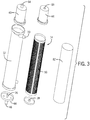
- Fig. 3 is an exploded view of the spinning membrane blood separation or fractionation system 10.
- the cylindrical housing 12 of the system 10 may house the internal member 14 concentrically and relatively rotatably about a common central axis.
- a membrane 62 may cover the internal member 14, and the shear gap 16 may be formed by the spacing between the housing 12 and the spinner 14, with the membrane 62 separating the different blood components.
- Optimal filtration leading to successful blood separation procedures may be dependent on several factors.
- One factor is the membrane filtration velocity, which is the volume of filtrate filtered per unit of time per area of membrane. If volume is measured in cm 3 , time is measured in minutes, and area of membrane is measured in cm 2 , the filtration rate may be measured in cm/min. Obtaining higher filtration rates while minimizing hemolysis may enhance separation efficiency and predictability.
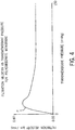
- Fig. 4 is a graphical depiction of the general relationship between filtration velocity and transmembrane pressure for a polycarbonate membrane.
- the curve of Fig. 4 shows that in general for polycarbonate membranes, filtration velocity increases proportionally with transmembrane pressure until a critical pressure P is reached beyond which filtration velocity no longer increases proportionally with transmembrane pressure.
- a further increase of transmembrane pressure beyond critical pressure P eventually leads to a decay of filtration velocity.
- nylon membranes after reaching a critical pressure point, filtration velocity does not decay but rather gradually continues with a positive slope until reaching an asymptote.
- Filtration velocity decreasing despite an increasing transmembrane pressure may be reflective of an obstruction of flow.
- the polycarbonate membrane may collapse against the internal member 14, especially as fluid outside the membrane 62 becomes denser towards orifices 34 and 46 as the plasma concentration outside the membrane decreases due to having crossed the membrane 62.
- Fig. 5 is a pictorial depiction of the interaction between the membrane 62 and the grooves 52 of the internal member 14.
- the plasma continuously crosses the membrane 62 into the grooves 52 of the internal member 14.
- the density outside the membrane 62 towards the orifices 34 and 46 increases and exerts increasing pressure on the membrane 62.
- the increasing pressure on membrane 62 may result in restricted flow within the grooves 52 of the internal member 14 due to collapsing of the polycarbonate membrane against a portion of a groove 52. Restricted flow within the grooves 52 may in turn result in restricted flow across the membrane 62 as well as restricted axial/longitudinal flow ( Fig. 9 ) towards opening 58a that leads to the plasma bridge 58b ( Fig. 1 ).
- Fig. 6 is a graphical depiction of the general relationship between filtration velocity and transmembrane pressure for a nylon membrane as well as a polycarbonate membrane.
- the nylon membrane curve after reaching its critical pressure point N at which the curve is no longer linear, does not decay but rather gradually continues with a positive slope until reaching an asymptote.
- the nylon membrane curve does not reach a peak level as high as that reached by the polycarbonate membrane.
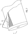
- Fig. 7 depicts one end of the internal rotor 14 with a membrane 62 comprising two layers.
- the two layers include a polycarbonate layer 62a and a nylon layer 62b.
- the nylon layer 62b is disposed underneath the polycarbonate layer 62a and acts as a scaffold/support for the polycarbonate layer 62a to prevent collapse of the polycarbonate membrane 62a into the grooves.
- the nylon layer 62b should have a thickness value and an air permeability value that is conducive to the nylon layer's ability to support the polycarbonate layer 62a while minimizing obstruction or hindrance of fluid flow.
- the nylon layer 62b may have a thickness of 40-80 microns and an air permeability of 50-130 cc/cm ⁇ 2/sec.
- Fig. 8 is a graphical depiction of the general relationship between filtration velocity and transmembrane pressure that results from a multi-layer membrane comprising a polycarbonate layer 62a and a nylon layer 62b.
- the filtration velocity reaches a level similar to the peak level exhibited by a polycarbonate membrane alone and also maintains a positive slope until reaching an asymptote, as exhibited by a nylon membrane.
- the nylon layer 62a acting as a support helps minimize or eliminate the decay due to membrane collapse exhibited by a polycarbonate membrane curve and thereby sustain peak levels even as transmembrane pressure increases.
- FIG. 9 a perspective side view of the internal rotor 14 is shown. Opening 58a that leads to plasma bridge 58b ( Fig. 1 ) is disposed near an end of the internal rotor proximal to outlet orifices 34 and 46. Grooves 52 separated by annular lands 54 may be disposed circumferentially and serially along the length of the internal member 14. Longitudinal groove 56a may run along the length of internal member 14 and be proximal to or coincide with plasma opening 58a leading to the plasma bridge 58b. Longitudinal groove 56a may also interconnect the circumferential grooves 52.
- Internal member 14 may have a second longitudinal groove 56b that also runs along the length of internal member 14 and interconnects the circumferential grooves 52 but is distal from or does not coincide with plasma opening 58a.
- Longitudinal groove 56b may provide a second collection pathway by which plasma flow can be directed towards the plasma bridge 58b through opening 58a.
- Fig. 10 a side view of the internal member 14 with an expanded view of the circumferential grooves 52 is shown.
- the nylon layer 62b of Fig. 7 providing a support for polycarbonate layer 62a and minimizing potential collapse of the membrane 62 against a portion of groove 52 may allow for deeper grooves 52 than would a polycarbonate layer alone.
- the practicable depth value of grooves 52 may be limited due to a positive relationship between depth value and difficulty of membrane collapse reversal, given that a membrane having collapsed deeper within a groove would be less likely to return to its un-collapsed position.
- Groove depth D in Fig. 10 is the distance between the top edge of the annular land 54 and the bottom of groove 52. In one embodiment, depth D may be greater than 0.033 inches and preferably approximately 0.066 inches up to 0.099 inches. In addition to deeper grooves being able to accommodate higher volume of fluid collection by the internal rotor 14, a greater depth D may allow for minimal hindrance of the collection process in the event that some collapse of the membrane 62 against a portion of groove 52 occurs.
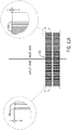
- Fig. 11A depicts a side view of the internal member 14 with an expanded view of the circumferential grooves 52 proximal to outlet orifices 34 and 46 and an expanded view of the circumferential grooves 52 proximal to inlet conduit 20.
- the likelihood of collapse of the membrane 62 against a portion of a groove 52 may increase.
- deeper grooves 52 may allow for continuous flow of filtrate through grooves 52 even though a top portion of space of the groove 52 is taken up by material of the membrane 62.
- circumferential grooves 52a proximal to outlet orifices 34 and 46 may each have depth D approximately 0.066 inches up to 0.099 inches, and circumferential grooves 52b proximal to inlet conduit 20 may each have depth d approximately 0.033 to 0.066 inches.
- Grooves 52b proximal to inlet conduit 20 may be shallower than grooves 52a proximal to orifices 34 and 46, as the density of fluid surrounding grooves 52b proximal to inlet conduit 20 may be lower than that of grooves 52a proximal to orifices 34 and 46.
- grooves 52 may gradually increase longitudinally in depth D along the length of internal member 14 from the end proximal to inlet conduit 20 to the end proximal to orifices 34 and 46.
- depth D may be as low as 0.033 inches at the end proximal to inlet conduit 20, incrementally increase to approximately 0.066 inches at a point m at any point between the end proximal to inlet conduit 20 and the end proximal to orifices 34 and 46, and incrementally increase up to 0.099 inches at the end proximal to outlet orifices 34 and 46.
- depth D may be as low as 0.033 inches at the end proximal to inlet conduit 20, incrementally increase to approximately 0.066 inches at a point m at any point between the end proximal to inlet conduit 20 and the end proximal to orifices 34 and 46, and incrementally increase up to 0.099 inches at the end proximal to outlet orifices 34 and 46.
- a groove 52c most proximal to orifices 34 and 46 may have depth D of 0.087 to 0.099 inches, while a groove 52g most proximal to the inlet conduit 20 may have depth d of 0.033 to 0.048 inches.
- a groove 52e proximal to point m may have depth D of approximately 0.066 inches and preferably in the range of 0.054 to 0.078 inches.
- a groove 52d located between groove 52c and 52e may have depth D of approximately 0.083 inches or any value from depth D of groove 52c to depth D of groove 52e. In one embodiment, groove 52d may have depth D in the range of 0.070 to 0.095 inches.
- a groove 52f located between groove 52e and 52g may have depth d of approximately 0.050 inches or any value from depth d of groove 52g to depth D of groove 52e. In one embodiment, groove 52f may have depth d in the range of 0.038 to 0.062 inches.
Landscapes
- Health & Medical Sciences (AREA)
- Chemical Kinetics & Catalysis (AREA)
- Chemical & Material Sciences (AREA)
- Heart & Thoracic Surgery (AREA)
- Animal Behavior & Ethology (AREA)
- Life Sciences & Earth Sciences (AREA)
- Vascular Medicine (AREA)
- Engineering & Computer Science (AREA)
- Anesthesiology (AREA)
- Biomedical Technology (AREA)
- Hematology (AREA)
- Veterinary Medicine (AREA)
- Public Health (AREA)
- General Health & Medical Sciences (AREA)
- Urology & Nephrology (AREA)
- Emergency Medicine (AREA)
- Separation Using Semi-Permeable Membranes (AREA)
- External Artificial Organs (AREA)
Claims (13)
- Dispositif de filtration de sang, comprenant :un boîtier cylindrique stationnaire (12) ayant une paroi intérieure ;un élément intérieur (14) qui est une centrifugeuse rotative qui est rotative concentriquement à l'intérieur du boîtier cylindrique (12) et montée à l'intérieur du boîtier (12), comprenant une surface extérieure ayant une membrane poreuse (62) disposée sur celle-ci ;dans lequel la surface extérieure comprend une série de rainures circonférentielles espacées les unes des autres (52) qui sont séparées par des plages annulaires (54) ;l'élément intérieur (14) étant rotatif relativement au boîtier (12), et définissant un espace annulaire (16) entre ceux-ci ;une entrée (20, 22) pour diriger un fluide dans l'espace annulaire (16) ;une première sortie (34) pour faire sortir un filtrat passant à travers la membrane ;une seconde sortie (46) pour diriger, depuis l'espace annulaire (16), le rétentat restant ; etdans lequel la membrane poreuse (62) comprend une première couche comprenant du nylon (62b) et une seconde couche comprenant du polycarbonate (62a), dans lequel la couche de nylon (62b) est disposée en dessous de la couche de polycarbonate (62a) en tant que support pour la couche de polycarbonate (62a).
- Dispositif selon la revendication 1, dans lequel l'entrée est configurée pour diriger un sang total dans l'espace annulaire (16), la première sortie (34) est configurée pour faire sortir un filtrat comprenant du plasma et/ou des plaquettes, et la seconde sortie (46) est configurée pour diriger, depuis l'espace annulaire (16), le rétentat restant comprenant des cellules sanguines.
- Dispositif selon l'une quelconque des revendications précédentes, dans lequel la surface extérieure comprend des rainures circonférentielles (52, 52a-g) ayant deux, ou plus, valeurs de profondeur, et dans lequel l'espace annulaire (16) est disposé entre le boîtier (12) et la surface extérieure de l'élément intérieur (14).
- Dispositif selon la revendication 3, dans lequel une première partie de la surface extérieure comprend des rainures circonférentielles (52 a-g) ayant une première valeur de profondeur, et une seconde partie de la surface extérieure comprend des rainures circonférentielles ayant une seconde valeur de profondeur (52 a-g).
- Dispositif selon la revendication 3, dans lequel les rainures circonférentielles (52 a-g) ont des valeurs de profondeur incrémentalement croissantes, le long d'une longueur de la surface extérieure, de 0,8382 mm (0,033 pouces) à 2,5146 mm (0,099 pouces).
- Dispositif selon la revendication 5, dans lequel les valeurs de profondeur croissantes procèdent dans une direction depuis une première extrémité de l'élément intérieur (14) proximale à l'entrée (20, 22) jusqu'à une seconde extrémité de l'élément intérieur (14) proximale à la première sortie (34) et/ou la seconde sortie (46).
- Dispositif selon la revendication 1, dans lequel la surface extérieure comprend des rainures circonférentielles (52, 52 a-g) ayant deux, ou plus, valeurs de profondeur ;
dans lequel une ouverture est disposée à une extrémité de la surface extérieure conduisant à un intérieur de l'élément intérieur (14) ;
dans lequel une pluralité de rainures longitudinales raccordent mutuellement les rainures circonférentielles ; et
dans lequel la première sortie (34) est en communication avec l'intérieur de l'élément intérieur (14) pour libérer un filtrat passant à travers la membrane (62). - Dispositif selon la revendication 7, dans lequel au moins trois rainures longitudinales interconnectent les rainures circonférentielles, dont au moins une coïncide avec l'ouverture disposée à l'extrémité de la surface extérieure et dont au moins une ne coïncide pas avec l'ouverture disposée à l'extrémité de la surface extérieure.
- Dispositif selon la revendication 7, dans lequel une première partie de la surface extérieure comprend des rainures circonférentielles (52-a-g) ayant une première valeur de profondeur, et une seconde partie de la surface extérieure comprend des rainures circonférentielles (52 a-g) ayant une seconde valeur de profondeur.
- Dispositif selon la revendication 7, dans lequel les rainures circonférentielles ont des valeurs de profondeur incrémentalement croissantes le long d'une longueur de la surface extérieure de 0,8382 mm (0,033 pouces) à 2,5146 mm (0,099 pouces).
- Dispositif selon la revendication 10, dans lequel les valeurs de profondeur croissantes continuent dans une direction depuis une première extrémité de l'élément intérieur (14) proximale à l'entrée (20, 22) jusqu'à une seconde extrémité de l'élément intérieur (14) proximale à la première sortie (34) et/ou la seconde sortie (46).
- Dispositif selon l'une quelconque des revendications précédentes, dans lequel la première couche de nylon (62b) et la seconde couche de polycarbonate (62a) comprennent des pores ayant des tailles dans la plage de 0,2 microns à 5 microns, et la couche de nylon (62b) comprend une épaisseur de 40 à 80 microns et une perméabilité à l'air de 50 à 130 cm3/cm2/sec.
- Dispositif selon l'une quelconque des revendications précédentes, dans lequel au moins une des première et seconde couches (62a, 62b) comprend au moins une d'une membrane maillée fibreuse, d'une membrane coulée et une membrane gravée sur piste.
Applications Claiming Priority (1)
| Application Number | Priority Date | Filing Date | Title |
|---|---|---|---|
| US201562271480P | 2015-12-28 | 2015-12-28 |
Publications (3)
| Publication Number | Publication Date |
|---|---|
| EP3187248A2 EP3187248A2 (fr) | 2017-07-05 |
| EP3187248A3 EP3187248A3 (fr) | 2017-10-04 |
| EP3187248B1 true EP3187248B1 (fr) | 2020-05-13 |
Family
ID=57570315
Family Applications (1)
| Application Number | Title | Priority Date | Filing Date |
|---|---|---|---|
| EP16204452.3A Active EP3187248B1 (fr) | 2015-12-28 | 2016-12-15 | Dispositif de séparation à membrane ayant une meilleure vitesse de filtration |
Country Status (2)
| Country | Link |
|---|---|
| US (1) | US11311842B2 (fr) |
| EP (1) | EP3187248B1 (fr) |
Cited By (2)
| Publication number | Priority date | Publication date | Assignee | Title |
|---|---|---|---|---|
| WO2022225800A1 (fr) * | 2021-04-19 | 2022-10-27 | Fenwal, Inc. | Dispositif de filtration du sang |
| EP3845258B1 (fr) * | 2020-01-03 | 2025-02-05 | Fenwal, Inc. | Système et procédé de lyse et d'élimination de globules sanguins rouges d'un produit de cellule |
Families Citing this family (1)
| Publication number | Priority date | Publication date | Assignee | Title |
|---|---|---|---|---|
| CN109529444A (zh) * | 2018-12-17 | 2019-03-29 | 刘向晖 | 一种去除血液样本中血细胞的过滤技术及过滤器 |
Citations (1)
| Publication number | Priority date | Publication date | Assignee | Title |
|---|---|---|---|---|
| US20030036085A1 (en) * | 2002-08-19 | 2003-02-20 | Salinaro Richard F | Membranes |
Family Cites Families (14)
| Publication number | Priority date | Publication date | Assignee | Title |
|---|---|---|---|---|
| GB2104401B (en) * | 1981-08-25 | 1985-03-20 | Krauss Maffei Ag | Support plate for centrifuges |
| AU4152085A (en) | 1984-03-21 | 1985-10-11 | Mclaughlin, W.F. | Method and apparatus for separation of matter from suspension |
| WO1988001193A1 (fr) | 1986-08-11 | 1988-02-25 | Hemascience Laboratories, Inc. | Procedes et systemes de lavage de cellules sanguines |
| US6045701A (en) | 1994-10-17 | 2000-04-04 | Baxter International Inc. | Method of filtering a fluid suspension with a membrane having a particular coating |
| AUPP081397A0 (en) | 1997-12-09 | 1998-01-08 | Mcgrath, Kevin Douglas | Filtration apparatus |
| AU5613700A (en) | 1999-07-16 | 2001-02-05 | Baxter International Inc. | Polyvinylidene difluoride membranes and methods for making such membranes |
| ATE354430T1 (de) | 1999-12-08 | 2007-03-15 | Baxter Int | Verfahren zur herstellung einer mikroporösen filtermembran |
| US7470245B2 (en) * | 2000-02-02 | 2008-12-30 | Xepmed, Inc. | Extracorporeal pathogen reduction system |
| WO2005037408A1 (fr) * | 2003-10-14 | 2005-04-28 | Donaldson Company, Inc. | Ensemble filtre a support plisse en v, et procedes correspondants |
| DE102007019051B3 (de) * | 2007-04-23 | 2008-10-09 | Fresenius Medical Care Deutschland Gmbh | Hohlfaserkapillarmembran und Verfahren zu deren Herstellung |
| EP2683470B1 (fr) * | 2011-03-11 | 2017-05-03 | Fenwal, Inc. | Dispositifs de séparation par membrane, systèmes et procédés les employant, systèmes et procédés de gestion de données |
| EP2698422B1 (fr) * | 2011-04-11 | 2016-06-22 | Kaneka Corporation | Préparation de matériau de cellules mononucléaires et procédé de préparation de cellules mononucléaires utilisant celle-ci |
| JP6284818B2 (ja) | 2014-04-24 | 2018-02-28 | 株式会社ダイセル | 微細孔と取り扱い強度を有した多孔膜積層体及びその製造方法 |
| WO2015167487A1 (fr) | 2014-04-30 | 2015-11-05 | Fenwal, Inc. | Procédé de maîtrise de l'encrassement et de l'activation de la protéine du complément pendant la filtration rotative à membrane de plasma à partir de sang total |
-
2016
- 2016-12-12 US US15/376,349 patent/US11311842B2/en active Active
- 2016-12-15 EP EP16204452.3A patent/EP3187248B1/fr active Active
Patent Citations (1)
| Publication number | Priority date | Publication date | Assignee | Title |
|---|---|---|---|---|
| US20030036085A1 (en) * | 2002-08-19 | 2003-02-20 | Salinaro Richard F | Membranes |
Cited By (2)
| Publication number | Priority date | Publication date | Assignee | Title |
|---|---|---|---|---|
| EP3845258B1 (fr) * | 2020-01-03 | 2025-02-05 | Fenwal, Inc. | Système et procédé de lyse et d'élimination de globules sanguins rouges d'un produit de cellule |
| WO2022225800A1 (fr) * | 2021-04-19 | 2022-10-27 | Fenwal, Inc. | Dispositif de filtration du sang |
Also Published As
| Publication number | Publication date |
|---|---|
| US11311842B2 (en) | 2022-04-26 |
| US20170182464A1 (en) | 2017-06-29 |
| EP3187248A3 (fr) | 2017-10-04 |
| EP3187248A2 (fr) | 2017-07-05 |
Similar Documents
| Publication | Publication Date | Title |
|---|---|---|
| EP3395425B1 (fr) | Système comprenant un dispositif de séparation de membrane | |
| US4808307A (en) | Couette membrane filtration apparatus for separating suspended components in a fluid medium using high shear | |
| US4871462A (en) | Enhanced separation of blood components | |
| ES2277360T3 (es) | Sistema para filtrar fluidos medicos y bilogicos. | |
| US4776964A (en) | Closed hemapheresis system and method | |
| EP0231623A2 (fr) | Dispositif de filtration à membrane couette pour la séparation de composants suspendus dans un fluide utilisant de forts efforts tranchants | |
| JPS59155758A (ja) | 血液の分別装置および分別法 | |
| EP3187248B1 (fr) | Dispositif de séparation à membrane ayant une meilleure vitesse de filtration | |
| US10335533B2 (en) | Device for separating blood into its components as well as a method for doing so and use of such a device | |
| US10729829B2 (en) | Systems and methods for platelet concentration with a spinning membrane separator | |
| US9033858B2 (en) | Method and apparatus for concentrating platelets from platelet-rich plasma | |
| US20030173274A1 (en) | Blood component separation device, system, and method including filtration | |
| EP3137127B1 (fr) | Procédé de maîtrise de l'encrassement et de l'activation de la protéine du complément pendant la filtration rotative à membrane de plasma à partir de sang total | |
| US11097037B2 (en) | Systems and methods for leukoreducing a red blood cell-containing fluid and concentrated red blood cells | |
| US9713669B2 (en) | Method for sized-based cell separation using spinning membrane filtration | |
| WO2022225800A1 (fr) | Dispositif de filtration du sang | |
| EP4008374B1 (fr) | Amorçage des séparateurs de membrane de rotation |
Legal Events
| Date | Code | Title | Description |
|---|---|---|---|
| PUAI | Public reference made under article 153(3) epc to a published international application that has entered the european phase |
Free format text: ORIGINAL CODE: 0009012 |
|
| STAA | Information on the status of an ep patent application or granted ep patent |
Free format text: STATUS: THE APPLICATION HAS BEEN PUBLISHED |
|
| AK | Designated contracting states |
Kind code of ref document: A2 Designated state(s): AL AT BE BG CH CY CZ DE DK EE ES FI FR GB GR HR HU IE IS IT LI LT LU LV MC MK MT NL NO PL PT RO RS SE SI SK SM TR |
|
| AX | Request for extension of the european patent |
Extension state: BA ME |
|
| PUAL | Search report despatched |
Free format text: ORIGINAL CODE: 0009013 |
|
| AK | Designated contracting states |
Kind code of ref document: A3 Designated state(s): AL AT BE BG CH CY CZ DE DK EE ES FI FR GB GR HR HU IE IS IT LI LT LU LV MC MK MT NL NO PL PT RO RS SE SI SK SM TR |
|
| AX | Request for extension of the european patent |
Extension state: BA ME |
|
| RIC1 | Information provided on ipc code assigned before grant |
Ipc: B01D 69/10 20060101ALI20170831BHEP Ipc: B01D 63/16 20060101AFI20170831BHEP Ipc: A61M 1/34 20060101ALI20170831BHEP |
|
| STAA | Information on the status of an ep patent application or granted ep patent |
Free format text: STATUS: REQUEST FOR EXAMINATION WAS MADE |
|
| 17P | Request for examination filed |
Effective date: 20180326 |
|
| RBV | Designated contracting states (corrected) |
Designated state(s): AL AT BE BG CH CY CZ DE DK EE ES FI FR GB GR HR HU IE IS IT LI LT LU LV MC MK MT NL NO PL PT RO RS SE SI SK SM TR |
|
| STAA | Information on the status of an ep patent application or granted ep patent |
Free format text: STATUS: EXAMINATION IS IN PROGRESS |
|
| 17Q | First examination report despatched |
Effective date: 20180713 |
|
| GRAP | Despatch of communication of intention to grant a patent |
Free format text: ORIGINAL CODE: EPIDOSNIGR1 |
|
| STAA | Information on the status of an ep patent application or granted ep patent |
Free format text: STATUS: GRANT OF PATENT IS INTENDED |
|
| INTG | Intention to grant announced |
Effective date: 20191212 |
|
| GRAS | Grant fee paid |
Free format text: ORIGINAL CODE: EPIDOSNIGR3 |
|
| GRAA | (expected) grant |
Free format text: ORIGINAL CODE: 0009210 |
|
| STAA | Information on the status of an ep patent application or granted ep patent |
Free format text: STATUS: THE PATENT HAS BEEN GRANTED |
|
| AK | Designated contracting states |
Kind code of ref document: B1 Designated state(s): AL AT BE BG CH CY CZ DE DK EE ES FI FR GB GR HR HU IE IS IT LI LT LU LV MC MK MT NL NO PL PT RO RS SE SI SK SM TR |
|
| REG | Reference to a national code |
Ref country code: GB Ref legal event code: FG4D |
|
| REG | Reference to a national code |
Ref country code: CH Ref legal event code: EP |
|
| REG | Reference to a national code |
Ref country code: DE Ref legal event code: R096 Ref document number: 602016036304 Country of ref document: DE |
|
| REG | Reference to a national code |
Ref country code: AT Ref legal event code: REF Ref document number: 1269511 Country of ref document: AT Kind code of ref document: T Effective date: 20200615 |
|
| REG | Reference to a national code |
Ref country code: LT Ref legal event code: MG4D |
|
| REG | Reference to a national code |
Ref country code: NL Ref legal event code: MP Effective date: 20200513 |
|
| PG25 | Lapsed in a contracting state [announced via postgrant information from national office to epo] |
Ref country code: GR Free format text: LAPSE BECAUSE OF FAILURE TO SUBMIT A TRANSLATION OF THE DESCRIPTION OR TO PAY THE FEE WITHIN THE PRESCRIBED TIME-LIMIT Effective date: 20200814 Ref country code: NO Free format text: LAPSE BECAUSE OF FAILURE TO SUBMIT A TRANSLATION OF THE DESCRIPTION OR TO PAY THE FEE WITHIN THE PRESCRIBED TIME-LIMIT Effective date: 20200813 Ref country code: SE Free format text: LAPSE BECAUSE OF FAILURE TO SUBMIT A TRANSLATION OF THE DESCRIPTION OR TO PAY THE FEE WITHIN THE PRESCRIBED TIME-LIMIT Effective date: 20200513 Ref country code: IS Free format text: LAPSE BECAUSE OF FAILURE TO SUBMIT A TRANSLATION OF THE DESCRIPTION OR TO PAY THE FEE WITHIN THE PRESCRIBED TIME-LIMIT Effective date: 20200913 Ref country code: LT Free format text: LAPSE BECAUSE OF FAILURE TO SUBMIT A TRANSLATION OF THE DESCRIPTION OR TO PAY THE FEE WITHIN THE PRESCRIBED TIME-LIMIT Effective date: 20200513 Ref country code: FI Free format text: LAPSE BECAUSE OF FAILURE TO SUBMIT A TRANSLATION OF THE DESCRIPTION OR TO PAY THE FEE WITHIN THE PRESCRIBED TIME-LIMIT Effective date: 20200513 Ref country code: PT Free format text: LAPSE BECAUSE OF FAILURE TO SUBMIT A TRANSLATION OF THE DESCRIPTION OR TO PAY THE FEE WITHIN THE PRESCRIBED TIME-LIMIT Effective date: 20200914 |
|
| PG25 | Lapsed in a contracting state [announced via postgrant information from national office to epo] |
Ref country code: LV Free format text: LAPSE BECAUSE OF FAILURE TO SUBMIT A TRANSLATION OF THE DESCRIPTION OR TO PAY THE FEE WITHIN THE PRESCRIBED TIME-LIMIT Effective date: 20200513 Ref country code: RS Free format text: LAPSE BECAUSE OF FAILURE TO SUBMIT A TRANSLATION OF THE DESCRIPTION OR TO PAY THE FEE WITHIN THE PRESCRIBED TIME-LIMIT Effective date: 20200513 Ref country code: HR Free format text: LAPSE BECAUSE OF FAILURE TO SUBMIT A TRANSLATION OF THE DESCRIPTION OR TO PAY THE FEE WITHIN THE PRESCRIBED TIME-LIMIT Effective date: 20200513 Ref country code: BG Free format text: LAPSE BECAUSE OF FAILURE TO SUBMIT A TRANSLATION OF THE DESCRIPTION OR TO PAY THE FEE WITHIN THE PRESCRIBED TIME-LIMIT Effective date: 20200813 |
|
| REG | Reference to a national code |
Ref country code: AT Ref legal event code: MK05 Ref document number: 1269511 Country of ref document: AT Kind code of ref document: T Effective date: 20200513 |
|
| PG25 | Lapsed in a contracting state [announced via postgrant information from national office to epo] |
Ref country code: NL Free format text: LAPSE BECAUSE OF FAILURE TO SUBMIT A TRANSLATION OF THE DESCRIPTION OR TO PAY THE FEE WITHIN THE PRESCRIBED TIME-LIMIT Effective date: 20200513 Ref country code: AL Free format text: LAPSE BECAUSE OF FAILURE TO SUBMIT A TRANSLATION OF THE DESCRIPTION OR TO PAY THE FEE WITHIN THE PRESCRIBED TIME-LIMIT Effective date: 20200513 |
|
| PG25 | Lapsed in a contracting state [announced via postgrant information from national office to epo] |
Ref country code: ES Free format text: LAPSE BECAUSE OF FAILURE TO SUBMIT A TRANSLATION OF THE DESCRIPTION OR TO PAY THE FEE WITHIN THE PRESCRIBED TIME-LIMIT Effective date: 20200513 Ref country code: CZ Free format text: LAPSE BECAUSE OF FAILURE TO SUBMIT A TRANSLATION OF THE DESCRIPTION OR TO PAY THE FEE WITHIN THE PRESCRIBED TIME-LIMIT Effective date: 20200513 Ref country code: AT Free format text: LAPSE BECAUSE OF FAILURE TO SUBMIT A TRANSLATION OF THE DESCRIPTION OR TO PAY THE FEE WITHIN THE PRESCRIBED TIME-LIMIT Effective date: 20200513 Ref country code: RO Free format text: LAPSE BECAUSE OF FAILURE TO SUBMIT A TRANSLATION OF THE DESCRIPTION OR TO PAY THE FEE WITHIN THE PRESCRIBED TIME-LIMIT Effective date: 20200513 Ref country code: IT Free format text: LAPSE BECAUSE OF FAILURE TO SUBMIT A TRANSLATION OF THE DESCRIPTION OR TO PAY THE FEE WITHIN THE PRESCRIBED TIME-LIMIT Effective date: 20200513 Ref country code: DK Free format text: LAPSE BECAUSE OF FAILURE TO SUBMIT A TRANSLATION OF THE DESCRIPTION OR TO PAY THE FEE WITHIN THE PRESCRIBED TIME-LIMIT Effective date: 20200513 Ref country code: EE Free format text: LAPSE BECAUSE OF FAILURE TO SUBMIT A TRANSLATION OF THE DESCRIPTION OR TO PAY THE FEE WITHIN THE PRESCRIBED TIME-LIMIT Effective date: 20200513 Ref country code: SM Free format text: LAPSE BECAUSE OF FAILURE TO SUBMIT A TRANSLATION OF THE DESCRIPTION OR TO PAY THE FEE WITHIN THE PRESCRIBED TIME-LIMIT Effective date: 20200513 |
|
| REG | Reference to a national code |
Ref country code: DE Ref legal event code: R097 Ref document number: 602016036304 Country of ref document: DE |
|
| PG25 | Lapsed in a contracting state [announced via postgrant information from national office to epo] |
Ref country code: SK Free format text: LAPSE BECAUSE OF FAILURE TO SUBMIT A TRANSLATION OF THE DESCRIPTION OR TO PAY THE FEE WITHIN THE PRESCRIBED TIME-LIMIT Effective date: 20200513 Ref country code: PL Free format text: LAPSE BECAUSE OF FAILURE TO SUBMIT A TRANSLATION OF THE DESCRIPTION OR TO PAY THE FEE WITHIN THE PRESCRIBED TIME-LIMIT Effective date: 20200513 |
|
| PLBE | No opposition filed within time limit |
Free format text: ORIGINAL CODE: 0009261 |
|
| STAA | Information on the status of an ep patent application or granted ep patent |
Free format text: STATUS: NO OPPOSITION FILED WITHIN TIME LIMIT |
|
| 26N | No opposition filed |
Effective date: 20210216 |
|
| PG25 | Lapsed in a contracting state [announced via postgrant information from national office to epo] |
Ref country code: SI Free format text: LAPSE BECAUSE OF FAILURE TO SUBMIT A TRANSLATION OF THE DESCRIPTION OR TO PAY THE FEE WITHIN THE PRESCRIBED TIME-LIMIT Effective date: 20200513 |
|
| REG | Reference to a national code |
Ref country code: CH Ref legal event code: PL |
|
| PG25 | Lapsed in a contracting state [announced via postgrant information from national office to epo] |
Ref country code: MC Free format text: LAPSE BECAUSE OF FAILURE TO SUBMIT A TRANSLATION OF THE DESCRIPTION OR TO PAY THE FEE WITHIN THE PRESCRIBED TIME-LIMIT Effective date: 20200513 |
|
| REG | Reference to a national code |
Ref country code: BE Ref legal event code: MM Effective date: 20201231 |
|
| PG25 | Lapsed in a contracting state [announced via postgrant information from national office to epo] |
Ref country code: IE Free format text: LAPSE BECAUSE OF NON-PAYMENT OF DUE FEES Effective date: 20201215 Ref country code: LU Free format text: LAPSE BECAUSE OF NON-PAYMENT OF DUE FEES Effective date: 20201215 |
|
| PG25 | Lapsed in a contracting state [announced via postgrant information from national office to epo] |
Ref country code: CH Free format text: LAPSE BECAUSE OF NON-PAYMENT OF DUE FEES Effective date: 20201231 Ref country code: LI Free format text: LAPSE BECAUSE OF NON-PAYMENT OF DUE FEES Effective date: 20201231 |
|
| PG25 | Lapsed in a contracting state [announced via postgrant information from national office to epo] |
Ref country code: TR Free format text: LAPSE BECAUSE OF FAILURE TO SUBMIT A TRANSLATION OF THE DESCRIPTION OR TO PAY THE FEE WITHIN THE PRESCRIBED TIME-LIMIT Effective date: 20200513 Ref country code: MT Free format text: LAPSE BECAUSE OF FAILURE TO SUBMIT A TRANSLATION OF THE DESCRIPTION OR TO PAY THE FEE WITHIN THE PRESCRIBED TIME-LIMIT Effective date: 20200513 Ref country code: CY Free format text: LAPSE BECAUSE OF FAILURE TO SUBMIT A TRANSLATION OF THE DESCRIPTION OR TO PAY THE FEE WITHIN THE PRESCRIBED TIME-LIMIT Effective date: 20200513 |
|
| PG25 | Lapsed in a contracting state [announced via postgrant information from national office to epo] |
Ref country code: MK Free format text: LAPSE BECAUSE OF FAILURE TO SUBMIT A TRANSLATION OF THE DESCRIPTION OR TO PAY THE FEE WITHIN THE PRESCRIBED TIME-LIMIT Effective date: 20200513 |
|
| PG25 | Lapsed in a contracting state [announced via postgrant information from national office to epo] |
Ref country code: BE Free format text: LAPSE BECAUSE OF NON-PAYMENT OF DUE FEES Effective date: 20201231 |
|
| P01 | Opt-out of the competence of the unified patent court (upc) registered |
Effective date: 20230515 |
|
| PGFP | Annual fee paid to national office [announced via postgrant information from national office to epo] |
Ref country code: GB Payment date: 20251229 Year of fee payment: 10 |
|
| PGFP | Annual fee paid to national office [announced via postgrant information from national office to epo] |
Ref country code: FR Payment date: 20251226 Year of fee payment: 10 |
|
| PGFP | Annual fee paid to national office [announced via postgrant information from national office to epo] |
Ref country code: DE Payment date: 20251229 Year of fee payment: 10 |