EP3395425B1 - Système comprenant un dispositif de séparation de membrane - Google Patents
Système comprenant un dispositif de séparation de membrane Download PDFInfo
- Publication number
- EP3395425B1 EP3395425B1 EP18178478.6A EP18178478A EP3395425B1 EP 3395425 B1 EP3395425 B1 EP 3395425B1 EP 18178478 A EP18178478 A EP 18178478A EP 3395425 B1 EP3395425 B1 EP 3395425B1
- Authority
- EP
- European Patent Office
- Prior art keywords
- plasma
- whole blood
- housing
- priming
- container
- Prior art date
- Legal status (The legal status is an assumption and is not a legal conclusion. Google has not performed a legal analysis and makes no representation as to the accuracy of the status listed.)
- Active
Links
Images






Classifications
-
- A—HUMAN NECESSITIES
- A61—MEDICAL OR VETERINARY SCIENCE; HYGIENE
- A61M—DEVICES FOR INTRODUCING MEDIA INTO, OR ONTO, THE BODY; DEVICES FOR TRANSDUCING BODY MEDIA OR FOR TAKING MEDIA FROM THE BODY; DEVICES FOR PRODUCING OR ENDING SLEEP OR STUPOR
- A61M1/00—Suction or pumping devices for medical purposes; Devices for carrying-off, for treatment of, or for carrying-over, body-liquids; Drainage systems
- A61M1/34—Filtering material out of the blood by passing it through a membrane, i.e. hemofiltration or diafiltration
-
- A—HUMAN NECESSITIES
- A61—MEDICAL OR VETERINARY SCIENCE; HYGIENE
- A61M—DEVICES FOR INTRODUCING MEDIA INTO, OR ONTO, THE BODY; DEVICES FOR TRANSDUCING BODY MEDIA OR FOR TAKING MEDIA FROM THE BODY; DEVICES FOR PRODUCING OR ENDING SLEEP OR STUPOR
- A61M1/00—Suction or pumping devices for medical purposes; Devices for carrying-off, for treatment of, or for carrying-over, body-liquids; Drainage systems
- A61M1/02—Blood transfusion apparatus
- A61M1/0272—Apparatus for treatment of blood or blood constituents prior to or for conservation, e.g. freezing, drying or centrifuging
-
- A—HUMAN NECESSITIES
- A61—MEDICAL OR VETERINARY SCIENCE; HYGIENE
- A61M—DEVICES FOR INTRODUCING MEDIA INTO, OR ONTO, THE BODY; DEVICES FOR TRANSDUCING BODY MEDIA OR FOR TAKING MEDIA FROM THE BODY; DEVICES FOR PRODUCING OR ENDING SLEEP OR STUPOR
- A61M1/00—Suction or pumping devices for medical purposes; Devices for carrying-off, for treatment of, or for carrying-over, body-liquids; Drainage systems
- A61M1/02—Blood transfusion apparatus
- A61M1/0281—Apparatus for treatment of blood or blood constituents prior to transfusion, e.g. washing, filtering or thawing
-
- A—HUMAN NECESSITIES
- A61—MEDICAL OR VETERINARY SCIENCE; HYGIENE
- A61M—DEVICES FOR INTRODUCING MEDIA INTO, OR ONTO, THE BODY; DEVICES FOR TRANSDUCING BODY MEDIA OR FOR TAKING MEDIA FROM THE BODY; DEVICES FOR PRODUCING OR ENDING SLEEP OR STUPOR
- A61M1/00—Suction or pumping devices for medical purposes; Devices for carrying-off, for treatment of, or for carrying-over, body-liquids; Drainage systems
- A61M1/14—Dialysis systems; Artificial kidneys; Blood oxygenators ; Reciprocating systems for treatment of body fluids, e.g. single needle systems for hemofiltration or pheresis
- A61M1/16—Dialysis systems; Artificial kidneys; Blood oxygenators ; Reciprocating systems for treatment of body fluids, e.g. single needle systems for hemofiltration or pheresis with membranes
- A61M1/26—Dialysis systems; Artificial kidneys; Blood oxygenators ; Reciprocating systems for treatment of body fluids, e.g. single needle systems for hemofiltration or pheresis with membranes and internal elements which are moving
- A61M1/262—Dialysis systems; Artificial kidneys; Blood oxygenators ; Reciprocating systems for treatment of body fluids, e.g. single needle systems for hemofiltration or pheresis with membranes and internal elements which are moving rotating
- A61M1/265—Dialysis systems; Artificial kidneys; Blood oxygenators ; Reciprocating systems for treatment of body fluids, e.g. single needle systems for hemofiltration or pheresis with membranes and internal elements which are moving rotating inducing Taylor vortices
-
- A—HUMAN NECESSITIES
- A61—MEDICAL OR VETERINARY SCIENCE; HYGIENE
- A61M—DEVICES FOR INTRODUCING MEDIA INTO, OR ONTO, THE BODY; DEVICES FOR TRANSDUCING BODY MEDIA OR FOR TAKING MEDIA FROM THE BODY; DEVICES FOR PRODUCING OR ENDING SLEEP OR STUPOR
- A61M1/00—Suction or pumping devices for medical purposes; Devices for carrying-off, for treatment of, or for carrying-over, body-liquids; Drainage systems
- A61M1/34—Filtering material out of the blood by passing it through a membrane, i.e. hemofiltration or diafiltration
- A61M1/3403—Regulation parameters
-
- A—HUMAN NECESSITIES
- A61—MEDICAL OR VETERINARY SCIENCE; HYGIENE
- A61M—DEVICES FOR INTRODUCING MEDIA INTO, OR ONTO, THE BODY; DEVICES FOR TRANSDUCING BODY MEDIA OR FOR TAKING MEDIA FROM THE BODY; DEVICES FOR PRODUCING OR ENDING SLEEP OR STUPOR
- A61M1/00—Suction or pumping devices for medical purposes; Devices for carrying-off, for treatment of, or for carrying-over, body-liquids; Drainage systems
- A61M1/34—Filtering material out of the blood by passing it through a membrane, i.e. hemofiltration or diafiltration
- A61M1/342—Adding solutions to the blood, e.g. substitution solutions
-
- A—HUMAN NECESSITIES
- A61—MEDICAL OR VETERINARY SCIENCE; HYGIENE
- A61M—DEVICES FOR INTRODUCING MEDIA INTO, OR ONTO, THE BODY; DEVICES FOR TRANSDUCING BODY MEDIA OR FOR TAKING MEDIA FROM THE BODY; DEVICES FOR PRODUCING OR ENDING SLEEP OR STUPOR
- A61M1/00—Suction or pumping devices for medical purposes; Devices for carrying-off, for treatment of, or for carrying-over, body-liquids; Drainage systems
- A61M1/34—Filtering material out of the blood by passing it through a membrane, i.e. hemofiltration or diafiltration
- A61M1/3496—Plasmapheresis; Leucopheresis; Lymphopheresis
-
- A—HUMAN NECESSITIES
- A61—MEDICAL OR VETERINARY SCIENCE; HYGIENE
- A61M—DEVICES FOR INTRODUCING MEDIA INTO, OR ONTO, THE BODY; DEVICES FOR TRANSDUCING BODY MEDIA OR FOR TAKING MEDIA FROM THE BODY; DEVICES FOR PRODUCING OR ENDING SLEEP OR STUPOR
- A61M1/00—Suction or pumping devices for medical purposes; Devices for carrying-off, for treatment of, or for carrying-over, body-liquids; Drainage systems
- A61M1/36—Other treatment of blood in a by-pass of the natural circulatory system, e.g. temperature adaptation, irradiation ; Extra-corporeal blood circuits
- A61M1/3621—Extra-corporeal blood circuits
- A61M1/3622—Extra-corporeal blood circuits with a cassette forming partially or totally the blood circuit
- A61M1/36224—Extra-corporeal blood circuits with a cassette forming partially or totally the blood circuit with sensing means or components thereof
-
- A—HUMAN NECESSITIES
- A61—MEDICAL OR VETERINARY SCIENCE; HYGIENE
- A61M—DEVICES FOR INTRODUCING MEDIA INTO, OR ONTO, THE BODY; DEVICES FOR TRANSDUCING BODY MEDIA OR FOR TAKING MEDIA FROM THE BODY; DEVICES FOR PRODUCING OR ENDING SLEEP OR STUPOR
- A61M1/00—Suction or pumping devices for medical purposes; Devices for carrying-off, for treatment of, or for carrying-over, body-liquids; Drainage systems
- A61M1/36—Other treatment of blood in a by-pass of the natural circulatory system, e.g. temperature adaptation, irradiation ; Extra-corporeal blood circuits
- A61M1/3621—Extra-corporeal blood circuits
- A61M1/3622—Extra-corporeal blood circuits with a cassette forming partially or totally the blood circuit
- A61M1/36225—Extra-corporeal blood circuits with a cassette forming partially or totally the blood circuit with blood pumping means or components thereof
-
- A—HUMAN NECESSITIES
- A61—MEDICAL OR VETERINARY SCIENCE; HYGIENE
- A61M—DEVICES FOR INTRODUCING MEDIA INTO, OR ONTO, THE BODY; DEVICES FOR TRANSDUCING BODY MEDIA OR FOR TAKING MEDIA FROM THE BODY; DEVICES FOR PRODUCING OR ENDING SLEEP OR STUPOR
- A61M1/00—Suction or pumping devices for medical purposes; Devices for carrying-off, for treatment of, or for carrying-over, body-liquids; Drainage systems
- A61M1/36—Other treatment of blood in a by-pass of the natural circulatory system, e.g. temperature adaptation, irradiation ; Extra-corporeal blood circuits
- A61M1/3621—Extra-corporeal blood circuits
- A61M1/3622—Extra-corporeal blood circuits with a cassette forming partially or totally the blood circuit
- A61M1/36226—Constructional details of cassettes, e.g. specific details on material or shape
- A61M1/362262—Details of incorporated reservoirs
-
- A—HUMAN NECESSITIES
- A61—MEDICAL OR VETERINARY SCIENCE; HYGIENE
- A61M—DEVICES FOR INTRODUCING MEDIA INTO, OR ONTO, THE BODY; DEVICES FOR TRANSDUCING BODY MEDIA OR FOR TAKING MEDIA FROM THE BODY; DEVICES FOR PRODUCING OR ENDING SLEEP OR STUPOR
- A61M1/00—Suction or pumping devices for medical purposes; Devices for carrying-off, for treatment of, or for carrying-over, body-liquids; Drainage systems
- A61M1/36—Other treatment of blood in a by-pass of the natural circulatory system, e.g. temperature adaptation, irradiation ; Extra-corporeal blood circuits
- A61M1/3621—Extra-corporeal blood circuits
- A61M1/3622—Extra-corporeal blood circuits with a cassette forming partially or totally the blood circuit
- A61M1/36226—Constructional details of cassettes, e.g. specific details on material or shape
- A61M1/362263—Details of incorporated filters
- A61M1/362264—Details of incorporated filters the filter being a blood filter
-
- A—HUMAN NECESSITIES
- A61—MEDICAL OR VETERINARY SCIENCE; HYGIENE
- A61M—DEVICES FOR INTRODUCING MEDIA INTO, OR ONTO, THE BODY; DEVICES FOR TRANSDUCING BODY MEDIA OR FOR TAKING MEDIA FROM THE BODY; DEVICES FOR PRODUCING OR ENDING SLEEP OR STUPOR
- A61M1/00—Suction or pumping devices for medical purposes; Devices for carrying-off, for treatment of, or for carrying-over, body-liquids; Drainage systems
- A61M1/36—Other treatment of blood in a by-pass of the natural circulatory system, e.g. temperature adaptation, irradiation ; Extra-corporeal blood circuits
- A61M1/3621—Extra-corporeal blood circuits
- A61M1/3622—Extra-corporeal blood circuits with a cassette forming partially or totally the blood circuit
- A61M1/36226—Constructional details of cassettes, e.g. specific details on material or shape
- A61M1/362265—Details of valves
-
- A—HUMAN NECESSITIES
- A61—MEDICAL OR VETERINARY SCIENCE; HYGIENE
- A61M—DEVICES FOR INTRODUCING MEDIA INTO, OR ONTO, THE BODY; DEVICES FOR TRANSDUCING BODY MEDIA OR FOR TAKING MEDIA FROM THE BODY; DEVICES FOR PRODUCING OR ENDING SLEEP OR STUPOR
- A61M1/00—Suction or pumping devices for medical purposes; Devices for carrying-off, for treatment of, or for carrying-over, body-liquids; Drainage systems
- A61M1/36—Other treatment of blood in a by-pass of the natural circulatory system, e.g. temperature adaptation, irradiation ; Extra-corporeal blood circuits
- A61M1/3621—Extra-corporeal blood circuits
- A61M1/3622—Extra-corporeal blood circuits with a cassette forming partially or totally the blood circuit
- A61M1/36226—Constructional details of cassettes, e.g. specific details on material or shape
- A61M1/362266—Means for adding solutions or substances to the blood
-
- A—HUMAN NECESSITIES
- A61—MEDICAL OR VETERINARY SCIENCE; HYGIENE
- A61M—DEVICES FOR INTRODUCING MEDIA INTO, OR ONTO, THE BODY; DEVICES FOR TRANSDUCING BODY MEDIA OR FOR TAKING MEDIA FROM THE BODY; DEVICES FOR PRODUCING OR ENDING SLEEP OR STUPOR
- A61M1/00—Suction or pumping devices for medical purposes; Devices for carrying-off, for treatment of, or for carrying-over, body-liquids; Drainage systems
- A61M1/36—Other treatment of blood in a by-pass of the natural circulatory system, e.g. temperature adaptation, irradiation ; Extra-corporeal blood circuits
- A61M1/3621—Extra-corporeal blood circuits
- A61M1/3627—Degassing devices; Buffer reservoirs; Drip chambers; Blood filters
- A61M1/3633—Blood component filters, e.g. leukocyte filters
-
- A—HUMAN NECESSITIES
- A61—MEDICAL OR VETERINARY SCIENCE; HYGIENE
- A61M—DEVICES FOR INTRODUCING MEDIA INTO, OR ONTO, THE BODY; DEVICES FOR TRANSDUCING BODY MEDIA OR FOR TAKING MEDIA FROM THE BODY; DEVICES FOR PRODUCING OR ENDING SLEEP OR STUPOR
- A61M1/00—Suction or pumping devices for medical purposes; Devices for carrying-off, for treatment of, or for carrying-over, body-liquids; Drainage systems
- A61M1/36—Other treatment of blood in a by-pass of the natural circulatory system, e.g. temperature adaptation, irradiation ; Extra-corporeal blood circuits
- A61M1/3687—Chemical treatment
-
- A—HUMAN NECESSITIES
- A61—MEDICAL OR VETERINARY SCIENCE; HYGIENE
- A61M—DEVICES FOR INTRODUCING MEDIA INTO, OR ONTO, THE BODY; DEVICES FOR TRANSDUCING BODY MEDIA OR FOR TAKING MEDIA FROM THE BODY; DEVICES FOR PRODUCING OR ENDING SLEEP OR STUPOR
- A61M1/00—Suction or pumping devices for medical purposes; Devices for carrying-off, for treatment of, or for carrying-over, body-liquids; Drainage systems
- A61M1/36—Other treatment of blood in a by-pass of the natural circulatory system, e.g. temperature adaptation, irradiation ; Extra-corporeal blood circuits
- A61M1/3692—Washing or rinsing blood or blood constituents
-
- A—HUMAN NECESSITIES
- A61—MEDICAL OR VETERINARY SCIENCE; HYGIENE
- A61M—DEVICES FOR INTRODUCING MEDIA INTO, OR ONTO, THE BODY; DEVICES FOR TRANSDUCING BODY MEDIA OR FOR TAKING MEDIA FROM THE BODY; DEVICES FOR PRODUCING OR ENDING SLEEP OR STUPOR
- A61M1/00—Suction or pumping devices for medical purposes; Devices for carrying-off, for treatment of, or for carrying-over, body-liquids; Drainage systems
- A61M1/36—Other treatment of blood in a by-pass of the natural circulatory system, e.g. temperature adaptation, irradiation ; Extra-corporeal blood circuits
- A61M1/38—Removing constituents from donor blood and storing or returning remainder to body, e.g. for transfusion
-
- B—PERFORMING OPERATIONS; TRANSPORTING
- B01—PHYSICAL OR CHEMICAL PROCESSES OR APPARATUS IN GENERAL
- B01D—SEPARATION
- B01D61/00—Processes of separation using semi-permeable membranes, e.g. dialysis, osmosis or ultrafiltration; Apparatus, accessories or auxiliary operations specially adapted therefor
- B01D61/14—Ultrafiltration; Microfiltration
- B01D61/18—Apparatus therefor
-
- B—PERFORMING OPERATIONS; TRANSPORTING
- B01—PHYSICAL OR CHEMICAL PROCESSES OR APPARATUS IN GENERAL
- B01D—SEPARATION
- B01D63/00—Apparatus in general for separation processes using semi-permeable membranes
- B01D63/06—Tubular membrane modules
-
- B—PERFORMING OPERATIONS; TRANSPORTING
- B01—PHYSICAL OR CHEMICAL PROCESSES OR APPARATUS IN GENERAL
- B01D—SEPARATION
- B01D63/00—Apparatus in general for separation processes using semi-permeable membranes
- B01D63/16—Rotary, reciprocated or vibrated modules
-
- A—HUMAN NECESSITIES
- A61—MEDICAL OR VETERINARY SCIENCE; HYGIENE
- A61M—DEVICES FOR INTRODUCING MEDIA INTO, OR ONTO, THE BODY; DEVICES FOR TRANSDUCING BODY MEDIA OR FOR TAKING MEDIA FROM THE BODY; DEVICES FOR PRODUCING OR ENDING SLEEP OR STUPOR
- A61M1/00—Suction or pumping devices for medical purposes; Devices for carrying-off, for treatment of, or for carrying-over, body-liquids; Drainage systems
- A61M1/36—Other treatment of blood in a by-pass of the natural circulatory system, e.g. temperature adaptation, irradiation ; Extra-corporeal blood circuits
- A61M1/3621—Extra-corporeal blood circuits
- A61M1/3622—Extra-corporeal blood circuits with a cassette forming partially or totally the blood circuit
- A61M1/36222—Details related to the interface between cassette and machine
-
- A—HUMAN NECESSITIES
- A61—MEDICAL OR VETERINARY SCIENCE; HYGIENE
- A61M—DEVICES FOR INTRODUCING MEDIA INTO, OR ONTO, THE BODY; DEVICES FOR TRANSDUCING BODY MEDIA OR FOR TAKING MEDIA FROM THE BODY; DEVICES FOR PRODUCING OR ENDING SLEEP OR STUPOR
- A61M2205/00—General characteristics of the apparatus
- A61M2205/33—Controlling, regulating or measuring
- A61M2205/3331—Pressure; Flow
-
- A—HUMAN NECESSITIES
- A61—MEDICAL OR VETERINARY SCIENCE; HYGIENE
- A61M—DEVICES FOR INTRODUCING MEDIA INTO, OR ONTO, THE BODY; DEVICES FOR TRANSDUCING BODY MEDIA OR FOR TAKING MEDIA FROM THE BODY; DEVICES FOR PRODUCING OR ENDING SLEEP OR STUPOR
- A61M2205/00—General characteristics of the apparatus
- A61M2205/50—General characteristics of the apparatus with microprocessors or computers
-
- A—HUMAN NECESSITIES
- A61—MEDICAL OR VETERINARY SCIENCE; HYGIENE
- A61M—DEVICES FOR INTRODUCING MEDIA INTO, OR ONTO, THE BODY; DEVICES FOR TRANSDUCING BODY MEDIA OR FOR TAKING MEDIA FROM THE BODY; DEVICES FOR PRODUCING OR ENDING SLEEP OR STUPOR
- A61M2205/00—General characteristics of the apparatus
- A61M2205/60—General characteristics of the apparatus with identification means
-
- B—PERFORMING OPERATIONS; TRANSPORTING
- B01—PHYSICAL OR CHEMICAL PROCESSES OR APPARATUS IN GENERAL
- B01D—SEPARATION
- B01D2313/00—Details relating to membrane modules or apparatus
- B01D2313/08—Flow guidance means within the module or the apparatus
-
- B—PERFORMING OPERATIONS; TRANSPORTING
- B01—PHYSICAL OR CHEMICAL PROCESSES OR APPARATUS IN GENERAL
- B01D—SEPARATION
- B01D2313/00—Details relating to membrane modules or apparatus
- B01D2313/20—Specific housing
- B01D2313/205—Specific housing characterised by the shape
-
- B—PERFORMING OPERATIONS; TRANSPORTING
- B01—PHYSICAL OR CHEMICAL PROCESSES OR APPARATUS IN GENERAL
- B01D—SEPARATION
- B01D2315/00—Details relating to the membrane module operation
- B01D2315/02—Rotation or turning
-
- G—PHYSICS
- G16—INFORMATION AND COMMUNICATION TECHNOLOGY [ICT] SPECIALLY ADAPTED FOR SPECIFIC APPLICATION FIELDS
- G16H—HEALTHCARE INFORMATICS, i.e. INFORMATION AND COMMUNICATION TECHNOLOGY [ICT] SPECIALLY ADAPTED FOR THE HANDLING OR PROCESSING OF MEDICAL OR HEALTHCARE DATA
- G16H10/00—ICT specially adapted for the handling or processing of patient-related medical or healthcare data
- G16H10/40—ICT specially adapted for the handling or processing of patient-related medical or healthcare data for data related to laboratory analysis, e.g. patient specimen analysis
Definitions
- the present application is related to systems incorporating separation devices of the type employing relatively rotating surfaces, at least one of which carries a membrane for filtering a component from fluid passed between the surfaces; and to the use of such systems to separate biological cells, such as red cells, plasma or white cells, from whole blood.
- such a collection typically employs a pre-assembled arrangement of tubing and containers or bags, including a flexible plastic primary container or bag for receiving a unit of whole blood from a donor and one or more "satellite" containers or bags.
- the blood is first collected in the primary container, which also contains an anticoagulant (typically containing sodium citrate, phosphate and dextrose-often referred to as CPD).
- CPD phosphate and dextrose-often
- a preservative (often called an "additive solution” or AS, and commonly containing a saline, adenine and glucose medium-which is referred to as SAG) may be included as part of a larger assembly of bags and tubes that are used in processing after the blood is collected.
- cell washing Another routine task performed by blood banks and transfusion center is "cell washing.” This may be performed to remove and/or replace the liquid medium (or a part thereof) in which the cells are suspended, to concentrate or further concentrate cells in a liquid medium, and/or to purify a cell suspension by the removal of unwanted cellular or other material.
- Spinning membrane separators have been found to provide excellent plasma filtration rates, due primarily to the unique flow patterns ("Taylor vortices") induced in the gap between the spinning membrane and the shell.
- the Taylor vortices help to keep the blood cells from depositing on and fouling or clogging the membrane.
- spinning membrane separators have been widely used for the collection of plasma, they have not typically been used for the collection of other blood components, specifically red blood cells. Spinning membrane separators also have not typically been used for cell washing.
- One example of a spinning membrane separator used in the washing of cells such as red blood cells is described in U.S. Patent No. 5,053,121 . However, the system described therein utilizes two separate spinners associated in series or in parallel to wash "shed" blood of a patient. Other descriptions of the use of spinning membrane separators for separation of blood or blood components may also be found in U.S. Patents Nos. 5,376,263 ; 4,776,964 ; 4,753,729 ; 5,135,667 and 4,755,300 .
- US5,783,085 discloses a system for separating at least one constituent from blood making use of a spinning membrane separator, comprising a membrane and a housing that are mutually separated by a gap, and provided with at least one port adjacent each of the top and the bottom of the housing and communicating with said gap, wherein the membrane is configured to spin about a generally vertically-oriented axis, wherein the spinning membrane separator further comprises a plasma outlet that communicates with the side of the membrane facing away from the gap.
- the spinning membrane is present on a surface of an internal member that is driven by a drive member.
- the separator is herein primed by a small volume of saline solution. After the priming whole blood is separated into plasma and concentrated red blood cells.
- the separator is part of a flow circuit further comprising a source of saline solution, an anticoagulant source, a plasma container, and tubings.
- the system further comprises a durable module including clamps and pumps.
- a spinning membrane blood separation or fractionation system is shown.
- a system 10 is typically used to extract plasma from whole blood obtained from an individual human donor.
- the plasma separation device and the associated drive unit are shown, although it should be understood that such a separator forms part of a disposable system including collection bags, bags of additives such as saline or ACD, return bags, tubing, etc., and that there are also associated control and instrumentation systems for operation of the device.
- the system 10 includes a generally cylindrical housing 12, mounted concentrically about a longitudinal vertical central axis.
- An internal member 14 is mounted concentric with the central axis.
- the housing and internal member is relatively rotatable.
- the housing is stationary and the internal member is a rotating spinner that is rotatable concentrically within the cylindrical housing 12.
- the boundaries of the blood flow path are generally defined by the gap 16 between the interior surface of the housing 12 and the exterior surface of the rotary spinner 14.
- the spacing between the housing and the spinner is sometimes referred to as the shear gap.
- a typical shear gap may be approximately 0.025 -0.050 inches (0.067-0.127 cm) and may be of a uniform dimension along the axis, for example, where the axis of the spinner and housing are coincident.
- the shear gap may also vary circumferentially for example, where the axis of the housing and spinner are offset.
- the shear gap also may vary along the axial direction, for example preferably an increasing gap width in the direction of flow to limit hemolysis.
- a gap width may range from about 0.025 to about 0.075 inches (0.06 - 0.19 cm).
- the axes of the housing and rotor could be coincident and the diameter of the rotor decrease in the axial direction (direction of flow) while the diameter of inner surface of the housing remains constant or the diameter of the housing increases while the rotor diameter remains constant, or both surfaces vary in diameter.
- the gap width may be about 0.035 inches (0.088 cm) at the upstream or inlet end of the gap and about 0.059 inches (0.15 cm) at the downstream end or terminus of the gap.
- the gap width could be varied by varying the outer diameter of the rotor and/or the inner diameter of the facing housing surface.
- the gap width could change linearly or stepwise or in some other manner as may be desired.
- the width dimension of the gap is preferably selected so that at the desired relative rotational speed, Taylor-Couette flow, such as Taylor vortices, are created in the gap and hemolysis is limited.
- Whole blood is fed from an inlet conduit 20 through an inlet orifice 22, which directs the blood into the blood flow entrance region in a path tangential to the circumference about the upper end of the spinner 14.
- the housing inner wall includes an exit orifice 34.
- the cylindrical housing 12 is completed by an upper end cap 40 having an end boss 42, the walls of which are nonmagnetic, and a bottom end housing 44 terminating in a plasma outlet orifice 46 concentric with the central axis.
- the spinner 14 is rotatably mounted between the upper end cap 40 and the bottom end housing 44.
- the spinner 14 comprises a shaped central mandrel or rotor 50, the outer surface of which is shaped to define a series of spaced-apart circumferential grooves or ribs 52 separated by annular lands 54.
- the surface channels defined by the circumferential grooves 52 are interconnected by longitudinal grooves 56.
- these grooves 56 are in communication with a central orifice or manifold 58.
- the surface of the rotary spinner 14 is at least partially, and is preferably substantially or entirely, covered by a cylindrical porous membrane 62.
- the membrane 62 typically has a nominal pore size of 0.6 microns, but other pore sizes may alternatively be used.
- Membranes useful in the washing methods described herein may be fibrous mesh membranes, cast membranes, track etched membranes or other types of membranes that will be known to those of skill in the art.
- the membrane may have a polyester mesh (substrate) with nylon particles solidified thereon, thereby creating a tortuous path through which only certain sized components will pass.
- the membrane may be made of a thin (approximately 15 micron thick) sheet of, for example, polycarbonate.
- pores may be larger than those described above.
- pores may be approximately 3-5 microns.
- the pores may be sized to allow small formed components (e.g., platelets, microparticles, etc.) to pass, while the desired cells (e.g., white blood cells) are collected.
- the rotary spinner is mounted in the upper end cap to rotate about a pin 64, which is press fit into the end cap 40 on one side and seated within a cylindrical bearing surface 65 in an end cylinder 66 forming part of the rotary spinner 14.
- the internal spinner or outer housing may be rotated by any suitable rotary drive device or system.
- the end cylinder 66 is partially encompassed by a ring 68 of magnetic material utilized in indirect driving of the spinner 14.
- a drive motor 70 exterior to the housing 12 is coupled to turn an annular magnetic drive member 72 that includes at least a pair of interior permanent magnets 74. As the annular drive member 72 is rotated, magnetic attraction between the ring 68 interior to the housing 12 and the magnets 74 exterior to the housing locks the spinner 14 to the exterior drive, causing the spinner 14 to rotate.
- the central outlet orifice 58 communicates with a central bore 76 in an end bearing 78 that is concentric with the central axis.
- An end bearing seat is defined by an internal shoulder 80 that forms a lower edge of a central opening 82.
- the central opening 82 communicates with the plasma outlet orifice 46. If the inner facing surface of the housing is covered entirely or partially by a membrane, a fluid collection or manifold may be provided beneath the membrane to collect plasma and direct it through a housing outlet (not shown).
- a spinning membrane separator that provides for improved plasma flow rates with an acceptably low level of hemolysis in the retained blood.
- Various factors are known to affect the filtration flow rate through spinning membrane separators, including the speed of rotation, the size of the gap between the spinning membrane and the shell, the effective area of the membrane, the concentration of red blood cells (or hematocrit), and the blood viscosity.
- Previous practices in the design of spinning membrane devices have been largely empirical, aided to some extent by vague phenomenological descriptions of the effects of the various design parameters on performance and hemolysis. This has proved to be inefficient in terms of development time and technical resources spent.
- the parameters of the spinning membrane separator of the present disclosure were determined based on quantitative differential models that take into account the local plasma velocity through the membrane and the local hemoglobin concentration. These differential models were integrated over the length of the device to provide a total plasma flow rate and plasma hemoglobin concentration at the outlet of the device.
- the method included the operational inputs based upon the existing Plasmacell-C separator geometry and operating conditions, including donor hematocrit, inlet blood flow rate, rotational speed, and effective membrane area. Also factored in were the geometric inputs of rotor radius, the width of the annular gap, and the length over which the integration is performed. See Table 1 below. To obtain predicted values for hypothetical separators, rotor radius and filtration length were varied from about 1 .0 to up to about 2.0 times the current Plasmacell- C values in increments of 0.05, providing a 21 x21 design space grid for each output variable of interest. For all devices, the housing taper and the gap at the outlet were held constant, and the inlet gap and rotational speed were varied accordingly.
- outputs of plasma flow rate and hemoglobin concentration were obtained for various values of the rotor radius, the rotational speed, and the integration length.
- the results of the models are shown in superimposed contour plots of the outlet hematocrit and outlet wall shear stress ( Fig. 3 ), the outlet hematocrit and the outlet plasma hemoglobin concentration ( Fig. 4 ), and the outlet hematocrit and Taylor number ( Fig. 5 ), all as a function of the relative filtration length and spinner radius.
- filtration length is understood to be axial length of the central mandrel or rotor 50 from the beginning to the end of grooves or ribs 52. It generally represents the length of the membrane available for filtration.
- Fig. 6 shows the plasma hemoglobin results as a function of filtration length and spinner radius in a three-dimensional plot, showing the increase in hemoglobin with larger devices. These results were then evaluated to provide the best balance of high plasma flow rate with acceptably low levels of hemolysis.
- the models predicted lengths and diameters for the rotor that would result in increased membrane areas whose use would also have acceptably low levels of hemolysis.
- Prototype separators (based on the results of the models) were made and tested to validate the results predicted by the models. Table 2, below, compares a current Plasmacell-C plasmapheresis device with two potential alternatives based on the models.
- a spinning membrane separator 10 includes a rotary spinner 14 which has a spinner diameter D, a filtration length FL, and an overall length LOA.
- the rotor has a diameter D of approximately 2.8 cm (1 .1 ") , a filtration length FL, of approximately 7.6 cm (3"), and an overall length, LOA, of approximately 12.7 cm (5.0").
- a spinning membrane separator may advantageously have a diameter D of 4.19 cm (1 .65”), a filtration length FL of 14.0 cn (5.52”), and an overall length LOA of 19.6 cm (7.7").
- Prototype spinning membrane separators were tested with bovine and human blood to validate the results predicted by the models. Blood flow rates of 100 ml/min were obtained with spinner speeds varying from 1000-3500 rpm. Outlet hematocrit levels of 80% and higher were obtained before high levels of fouling of the membrane were experienced. Collection times for 880 ml of plasma ranged from between approximately 18 and 20 minutes.
- the residence time of the red blood cells in the shear gap has a direct relationship to the amount of hemolysis.
- flow regions exist along the axial length of the rotor where the fluid flows is relatively stagnant, resulting in pockets of hemolysis.
- the quality of the collected red blood cells is degraded.
- a method for creating separate fluid flow regions in the gap of a spinning membrane separator without the use of seals is disclosed.
- the separate flow regions reduce or minimize the influence of mixing of the fluids between the two flow regions.
- the separate flow regions are achieved by having a raised rib or ridge in the gap to reduce or minimize the gap between the spinner and the outer cylinder.
- the ridge or rib is provided on the surface of the rotor beyond where the spinning membrane is attached thereto.
- the ridge is preferably located so as to define the boundary of the high perfusion flow region.
- the radial size of the ridge is inversely proportional to the decree of mixing allowed between the two regions defined thereby, with a larger radial dimension for the ridge allowing for less mixing.
- the axial dimension or extent of the ridge is also inversely proportional to the degree of mixing allowed, with a larger axial dimension allowing for less mixing.
- the axial dimension of the ridge is preferably at least one gap-size long to minimize the formation of adjacent Taylor vortices causing unwanted mixing.
- FIG. 8 a schematic cross sectional representation of a spinning membrane separation device 10 is shown.
- the device comprises a fixed outer cylinder 12 and a rotating inner cylinder 14 having a filter member carried thereon.
- the inner cylinder is provided with a radial ridge 90. This ridge serves to divide the gap 16 between the spinner and the outer housing into two fluid regions.
- a first fluid region 92 has a stagnant, non-perfused region of flow, typically on the portion of the spinner that extends beyond the filter membrane.
- a second fluid region 94 which typically contacts the filter membrane, has a highly perfused region of flow.
- the first fluid region 92 is not perfused, blood residing therein is exposed to increased shear stresses for longer periods of time than the blood in the second fluid region 94.
- the blood in the first fluid region 92 may often become hemolyzed and has high concentrations of free hemoglobin (Hb).
- the ridge 90 inhibits fluid flow between the two fluid regions, thus minimizing the extent of mixing of the Hb-contaminated blood in the first region 92 with the low Hb blood in the second region 94.
- the ridge 90 is shown as being integral with the rotor, it could also be formed on the inside of the outer cylinder to achieve the same effect.
- the axial dimension of the ridge should be at least one-gap size long.
- a typical spinning membrane separation device for performing plasmapheresis typically has a gap between the spinner and the containment wall of from 0.058 cm (0.023”) to 0.067 cm (0.0265"), and a ridge in accordance with the present application could have an axial dimension within the same general range.
- larger axial dimensions for the ridge will result in reduced mixing and, in one example, a rotor having a radially-extending ridge with an axial dimension of 0.23 cm (0.092”) has been found to be effective.
- a spinning membrane separation device as described above may be advantageously used in various blood processing systems and methods for which prior devices generally were not suited, particularly systems and process for obtaining Red Blood Cells.
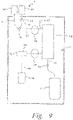
- the spinner is used for "back lab” processing of previously collected whole blood, as shown in Figs. 9-15A .
- a disposable fluid flow circuit or module A and a reusable durable controller or module B configured to cooperate with and control flow through the fluid circuit A are schematically illustrated.
- the disposable fluid circuit A as illustrated in Fig. 9 includes various components interconnected by flexible plastic tubing defining flow paths between the components.
- the circuit is preferably fully pre-assembled and pre-sterilized with the possible exception of the unit of whole blood container and the cell preservative container. More specifically, the illustrated disposable circuit in Fig. 9 includes whole blood container 101, a cell preservation solution container 102, blood component separator 108, plasma collection container 112, optional leukocyte reduction filter 113, and red cell collection container 115. While not illustrated in Fig.
- the reusable module B may have hangers with associated weigh scales for supporting any or all of the containers 101, 102, 112 and 115.
- hangers/ weigh scales may not be illustrated, but are understood to be part of the described systems.
- the whole blood collection container 101 may be any suitable container but is typically a flexible plastic pouch or bag in which approximately 450 ml of whole blood have been previously collected.
- the container 101 may be part of a separate system during collection and then joined to the rest of the fluid circuit A or actually part of the circuit A at the time of collection.
- the whole blood is mixed with an anticoagulant located in the primary container to prevent premature coagulation.
- "whole blood” as used herein includes blood mixed with anticoagulant.
- Flexible plastic tubing 105 is attached to the whole blood collection container, such as by a sterile connection device or other suitable attachment mechanism, and defines a whole blood fluid flow path between the whole blood container 101 and a junction with cell preservative solution tubing 103, which extends from the cell preservation solution container 102 to the flow path junction.
- the flow path junction between the whole blood flow path and all preservative flow path is located at inlet clamp 116. From the junction, the flow path extends through tubing 107 to an inlet port in the separator 108.
- the separator housing has an outlet that communicates with the gap between the housing and rotor and with concentrated red cell flow path tubing 110 for withdrawing concentrated red cells from the separator gap.
- the housing includes an outlet from the rotor that communicates with the side of the membrane facing away from the gap (for example, the interior of the rotor) and communicates with plasma flow path tubing 111.
- the disposable fluid flow circuit A optionally includes a leukocyte reduction filter 113, which may be of any suitable well known construction for removing leukocytes from concentrated red cells without unduly causing hemolysis of red cells or reducing the number of red cells in the collected product.
- the concentrated red cells flow from the leukocyte reduction filter 113 through a continuation 114 of the concentrated red cell flow path into storage container 15 which may be of any suitable plastic material compatible with red cell storage.
- the reusable or durable controller module B preferably includes a hematocrit sensor 104 for detecting the hematocrit and the whole blood flowing from the whole blood container 101 .
- the hematocrit detector may be of any suitable design or construction but is preferably as described in U.S. Patent No. 6,419,822 .
- the durable reusable controller or control module B also includes an inlet clamp 116 which may be operated to control fluid from the whole blood container 101 or the cell preservative container 102 or, optionally, simultaneously and proportionally from both of the containers 101 and 102.
- the reusable module includes an inlet pump 106, which also may be of any suitable construction, and may be, for example, a peristaltic type pump which operates by progressive compression or squeezing of the tubing 107 forming the inlet flow path into the separator, a flexible diaphragm pump or other suitable pump.
- a pressure sensor 117 communicates with the inlet flow path between the pump 106 and the separator 108 to determine the inlet pumping pressure. The sensor may output to the control system to provide an alarm function in the event of an over-pressure condition or an under-pressure condition or both.
- the reusable module also includes an outlet pump 109 that is associated with the outlet flow path 110, and functions in the manner similar to that described with respect to inlet pump 106. It also may be of any suitable construction such as a peristaltic pump, a flexible diaphragm or other suitable pumping structure.
- the plasma flow path 111 exiting the separator is preferably not controlled by a pump, and the volumetric flow rate through the plasma flow path tubing is the difference between the inlet volumetric flow rate from pump 106 and the outlet volumetric flow rate from pump 109.
- Reusable module B may, however, also include a clamp 118 for controlling flow of plasma through the plasma flow path tubing 111.
- the disposable module A may also include a plasma collection container 112 in fluid communication with the plasma flow path for receiving plasma separated by the separator 108. Because the plasma passes through a porous membrane in the separator 108, the plasma that is collected in container 112 is largely cell free plasma and may be suitable for administration to patients, freezing for storage or subsequent processing.
- Fig. 10 generally shows the flow path(s) of fluid through the system illustrated in Fig. 9 . Specifically, it shows flow of whole blood from the single unit whole blood container 101 through the whole blood hematocrit detector 104, to a junction in the flow path located at the binary clamp 116.
- Cell preservation solution such as a red cell preservation solution, flows from the red cell container 102 also to the junction at the binary clamp 116.
- the binary clamp allows the flow of whole blood or cell preservative downstream into the remainder of the system.
- the clamp 116 could be a proportional clamp to allow a selected proportionate flow of whole blood and red cell preservative simultaneously.
- the separation device employs a relatively rotating housing and rotor, at least one of which carries a membrane through which plasma is allowed to pass.
- the membrane is carried on the surface of the rotor and plasma passes through the membrane and through internal passage labyrinth within the rotor exiting eventually to the plasma collection container 112.
- the device is commonly referred to a spinning membrane separator, as shown in Fig. 10 .
- the membrane could potentially be mounted on the inside surface of the housing, facing the gap between the inside surface of the housing wall and the outer surface of the membrane, or a membrane could be carried on both the outer surface of the rotor and the inner surface of the housing so that plasma flows through membranes simultaneously, therefore potentially increasing the separation speed or performance of the separator 108.
- the concentrated red cells flow through the housing outlet communicating with the gap between rotor and housing and through the red cell flow path 110 and the outlet pump 109, which controls the volumetric flow rate of the concentrated red cells.
- the outlet pump 109 pumps the concentrated red cells into the red cell collection container 115 and, optionally, through a leukocyte reduction filter located in the red cell flow path between the pump 109 and the collection container 115.
- the force of the pump pushing the concentrated red cells through the leukocyte reduction filter helps to maintain the processing time within a reasonable range, as compared, for example, to the time it would be required for gravity flow of concentrated red cells through a leukocyte reduction filter in a manual setting.
- the plasma separated by the separator 108 flows from the separator device, for example, from an outlet communicating with a labyrinth of passageways within the rotor through a single control clamp 118 and to the plasma collection container 112.
- the plasma passes through the membrane, it is largely cell free and suitable for subsequent administration to patients, freezing, and/or for the processing, such as by fractionation to obtain plasma components for use in other therapeutic products.
- the system could also include a filter such as a leukocyte reduction filter in the plasma flow line 111 if desired.
- Fig. 11 illustrates one version of a potential system employing both a disposable fluid circuit module A and a reusable or durable controller module B. Although shown assembled, the fluid circuit module A and durable module B have separate and independent utility and may be used with other systems as well.
- the disposable module A is conveniently mounted to the face of the reusable module B, which has associated hangars or supports, some of which may be associated with weight scales, for supporting the various containers of the disposable system.
- the disposable module is, as indicated earlier, preferably preassembled, and pre-sterilized.
- the cell preservative solution container may be pre-attached as part of the disposable system or may be added later, such as by a sterile connection device or other suitable attachment.
- the whole blood container which contains the unit of previously collected whole blood may also be pre-attached to the pre-assembled fluid circuit or attached by way of a sterile connection device or other suitable attachment mechanism.
- the face of the reusable module B includes, in this embodiment, a separate solution clamp 116a for controlling flow of cell preservation solution from the solution container 102, which is hung from an elevated solution support pole.
- the whole blood container 101 is hung from a weight scale.
- the weight scale may be of conventional construction and may provide a weight measurement signal that may be used by the control system of the module B for sensing the amount of whole blood that remains in the container and/or the amount of whole blood that has been processed through the system.
- the disposable system includes a red cell flow path 105 that extends from the whole blood container, through the hematocrit detector 104, and through a separate whole blood clamp 116b for controlling flow of whole blood from the container into the system.
- the cell preservative solution flow path 103 and the whole blood flow path 105 combine at a junction, such as a v-site or y-site, upstream of the inlet pump 106.
- the combined flow path extends through the inlet pump and to an inlet on the separator device 108.
- the reusable module B includes a drive unit, such as a magnetic drive unit for causing rotation of the rotor within the separator housing without requiring drive members or components to physically extend through the housing.
- the rotor includes a magnetically coupled drive element that is rotated by the magnetic drive unit associated with the reusable module. This system is described more fully in U.S. Patent No. 5,194,145 to Schoendorfer .
- the concentrated red cell outlet from the separator 108 is attached to the red cell flow path 110, which extends through outlet pump 109 and to an inlet into the optional leukocyte reduction filter 113.
- Filter media located between the inlet and outlet of the leukocyte reduction filter substantially removes leukocytes from the red cells. From the filter outlet, the red cell flow path tubing 114 conveys the red cells into the red cell collection container 115.
- Plasma is conducted from the plasma outlet of the separator through a plasma flow control clamp 118 and into the plasma collection container 112.
- the concentrated red cell container 115 and the plasma container 112 are suspended from weight scales which may be in electronic communication with the control system of the durable or reusable module B to provide information regarding the amount of concentrated red cells and/or plasma collected from the whole blood or the rate of collection.
- Primer refers to the method by which the filter membrane is prepared (i.e., wetted) prior to use. Wetting with a fluid helps to displace air present in the matrix of the membrane prior to pressure- induced fluid flow through the membrane.
- a low viscosity non-biological fluid such as a cell preservation solution (red cell solution such as, Adsol solution) is used for wetting to allow the most effective displacement of air.
- cell preservation solution red cell solution such as, Adsol solution
- fluid is removed from the cell preservation solution bag 102 by the inlet pump 106 until the solution line 103, whole blood line 105, inlet line 107, and spinning membrane device 108 are completely filled with the solution.
- the inlet pump 106 may move both clockwise and counterclockwise during the prime.
- the purpose of the solution prime is to prevent an air-blood interface from forming by creating a solution-blood interface and to wet the membrane within the separation device. Each is a measure taken to reduce the hemolysis of red blood cells.
- the cell solution flow path 103 will be closed by the inlet clamp 116.
- the illustrated inlet clamp is a binary clamp that can close either the cell preservation solution flow path 103 or the whole blood flow path 107.
- Whole blood will then be pumped through the whole blood flow path 105 and the inlet flow path 107 by the inlet pump 106 into the separator 108.
- Inlet pump 106 flow rates can vary from about 10 ml/min to 150 ml/min depending on desired product outcomes for a specific procedure.
- the whole blood leaves the whole blood container 101 it will pass through the whole blood hematocrit detector 104 which will generate an estimation of the whole blood hematocrit through IR LED reflectance measurements. Details of the hematocrit detector are explained in U.S.
- Patent No. 6,419,822 (Title: Systems and methods for sensing red blood cell hematocrit).
- the whole blood hematocrit value is required for an initial control algorithm of the illustrated system, but may not be essential in other systems.
- the system will begin to draw plasma from the separator which separates the whole blood entering the spinning membrane device into a red cell concentrate and virtually cell free plasma.
- red blood cells at approximately 80-85% hematocrit will be pumped out of the separator 108 through the red cell flow path 110 and into the red blood cell leukofilter 113 by the outlet pump 109.
- the outlet pump forces the packed red blood cells through the red blood cell leukofilter 113 and the red cell concentrate which exits the red blood cell leukofilter 13 through the red blood cell line 114 and into the red blood cell product bag 115 will be successfully depleted of white blood cells and also depleted of platelets. It is also possible to complete a whole blood automated separation without the use of a red blood cell leukofilter 113. In this case the red blood cell leukofilter 114 would be removed from the system and the red blood cell product 115 would not be depleted of white blood cells or platelets.
- plasma will flow through the plasma flow path 111 into the plasma bag 112 at a flow rate equal to the difference between the inlet pump 106 flow rate and outlet pump 109 flow rate as is currently done in other spinning membrane separation applications like that applied in the Autopheresis- C ® instrument sold by Fenwal, Inc..
- the pressure across the membrane generated by the offset in flow rates is monitored by the pressure sensor 117.
- the pressure measurements are used to control the plasma flow rate using the algorithm described in U.S. Patent Application Serial No. 13/095,633, filed April 27, 2011 (Title: SYSTEMS AND METHODS OF CONTROLLING FOULING DURING A FILTRATION PROCEDURE), granted as US8,840,790 .
- the system in Figures 9-11 will continue to separate packed red blood cells and plasma until the whole blood bag 101 is empty as detected by air passing through the whole blood hematocrit detector 104. At this point the whole blood line 105 will be closed and the cell preservative solution line will be opened by the inlet clamp 116 to start the solution rinse or flush.
- preservative solution will be removed from the solution bag 102 and pumped into the separator 108 by the inlet pump 106.
- the plasma flow path 111 is closed by the plasma clamp 118 during the solution rinse.
- the solution rinse is used to flush any blood remaining in the system into the red blood cell product container 115.
- the solution rinse will also increase the red blood cell product container 115 volume to the level desired for proper red blood cell storage. After the solution rinse is finished the separation of the whole blood unit is complete.
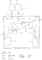
- a further alternative two-pump system is shown.
- This embodiment differs from that in Fig. 9 primarily in that the fluid from the blood cell preservative solution is added after the red blood cells have been separated from the whole blood.
- a container/bag 101 containing previously- collected whole blood preferably already combined with an anticoagulant
- Pump 106 cooperates with tubing 107 to pump whole blood to the separator 108.
- Container 102 containing the red blood cell preservative additive solution is connected to the collection container 115 for the separated red blood cells through tubing 1 14, through which the separated red blood cells are also directed to container 115 through the leukocyte filter 1 14.
- Container 102 for the additive solution may be supplied as part of the disposable system A, and may be joined to the remainder of the disposable (after sterilization by, e.g., gamma or E-Beam processing) during final packaging after the remainder of the disposable has been sterilized (by, e.g., moist heat processing).
- the container 102 may be formed integrally with the remainder of the disposable.
- both the container 102 and the whole blood container 101 may be separate from the remainder of the disposable and connected at the time of use through, e.g., sterile spike connections 170, shown schematically in Fig. 10 .
- Such spike connections preferably include a 0.2 micron filter to maintain sterility.
- tubing 103 connecting the additive solution container 102 to the leukocyte filter 62 may also be cooperatively engaged by the pump 109.
- pump 109 may be a dual pump head that flows both the additive solution and the red blood cells exiting the separator 108 to control the flow rate of each based upon the inside diameter of the tubings 103 and 110.
- the embodiment of Fig .12 also utilizes an additional pressure sensor 117b to monitor the back pressure from the leukocyte filter 113. Should the back pressure become excessive, as in the event of filter occlusion, the sensor will act to control the flow rate in order to ensure that the disposable does not rupture due to excessive pressure.
- a method for priming a membrane filter is provided by which is more likely that the maximum amount of the surface area of the filter membrane is wetted, thus maximizing the membrane area available for filtration/separation.
- the wetting solution enters at the top inlet port of the spinning separator, and gravity pulls the fluid toward the outlet at the bottom of the separator.
- the surface tension of the priming fluid will form an air-fluid interface that may move unevenly across the membrane surface, creating disruptions.
- a method for priming a membrane separator that more uniformly wets the membrane surface by providing a more uniform air-fluid interface during priming.
- priming fluid is introduced into the separator so that it works against the force of gravity as the fluid-air interface advances in an upward direction across the surface of the membrane. This helps to ensure a more uniform wetting of the membrane, as the air displaced during priming is able to move in a single direction without being trapped as the air-fluid interface advances across the membrane.
- the priming fluid is introduced into the separator through a port at the bottom of the separator.
- the priming solution advances upwardly in the housing of the separator against the force of gravity to wet the surface of the membrane, with the air being expelled from the separator through a port at the top of the separator. While this "bottom to top” priming is described in the context of a spinning membrane separator, it is also applicable to any type of membrane separator that requires fluid priming prior to use.
- the separator 108 is oriented vertically, so that the membrane separator and housing are relatively rotatable to one another about a generally-vertical axis, with the port for receiving the whole blood at the top of the separator and the ports through which the separated RBCs and plasma exit at the bottom of the separator.
- the priming solution may be introduced through one of the exit orifice 34 or plasma outlet orifice 46 of the spinning membrane separator 10, while air is expelled through the inlet orifice 22.
- separator 10 may be inverted or upturned for priming, so that the exit orifice 34 and plasma outlet orifice 46 are at the top of the separator 10, and the inlet orifice 22 is at the bottom of the separator 10.
- the priming solution may then be introduced through the inlet 22, with the fluid-air interface advancing upwardly and air being expelled through either or both of the exit orifice 34 and the plasma outlet orifice 46.
- the separator 10 may be returned to its original orientation, with the inlet orifice 22 at the top and the exit orifice 34 and plasma outlet orifice 46 at the bottom.
- FIG. 12A A further alternative in which the "bottom to top" priming of the blood separator 108 described above may be used is shown in Fig. 12A - not in accordance with the invention.
- the inlet line 107 for the whole blood connects to the lower port of the separator 108 (to which the outlet line 110 had been attached in the embodiment of Fig. 12 ), while the outlet line 110 is connected to the port at the top of the separator 108 (to which the inlet line 107 had been attached in the embodiment of Fig. 12 ).
- the inlet line 107 for the whole blood connects to the lower port of the separator 108 (to which the outlet line 110 had been attached in the embodiment of Fig. 12 ), while the outlet line 110 is connected to the port at the top of the separator 108 (to which the inlet line 107 had been attached in the embodiment of Fig. 12 ).
- clamp 116B is opened and pump 106 activated to flow whole blood (preferably with anticoagulant added) through the inlet line 107 so that it enters the separator 108 through the port at the lower end of the housing.
- whole blood preferably with anticoagulant added
- the separator housing air is expelled through the top port, to substantially eliminate all air from the device, and the filter membrane is wetted.
- the system continues to operate as shown in Fig. 12A to separate the whole blood into plasma, received in container 112, and red blood cells, received in container 115.
- the separator may be rinsed with additive solution from container 102.
- Figs. 14 and 15 a blood separation system according to the claimed invention is shown.
- the system of Figs. 14 and 15 is similar to that of Figs. 9 , 11 , and 12 except that the durable module B includes a third pump 119 for selectively flowing additive solution to either the separator 108 during the priming phase (as shown in Fig. 14 ), or to the separated red blood cells during the separation phase (as shown in Fig. 15 ).
- the system of Figs. 14 and 15 also includes a further clamp 120 for selectively permitting or preventing flow of fluid (separated red blood cells and additive solution) through the leukofilter 113 and into the red blood cell container 115.
- clamp 20 Prior to priming, clamp 20 could briefly remain open and pump 109 could pump residual air from container 115 and filter 113, minimizing the amount of air remaining in container 115 at the end of the procedure.
- the system of Figs. 14 and 15 employs bottom to top priming of the separator 108, except using additive solution for the priming fluid instead of whole blood.
- air from the disposable system A is pushed to the whole blood container 101.
- the system is operated as shown in Fig. 15 .
- additive solution is pumped to the separator 108 (as shown in the prime phase illustrated in Fig. 14 ) to rinse the separator.
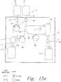
- Fig. 15A a further alternative system is shown - not in accordance with the invention.
- the system of Fig. 15A is like that of Figs. 14 and 15 , in that the reusable component B comprises three pumps 106, 109, and 1 19.
- the system of Fig. 15A is similar to that of Fig. 12A , in that the inlet line 107 for the whole blood is connected to the port at the bottom of the separator 108, while the outlet line for the separated red blood cells is connected to the port at the top of the separator.
- whole blood is used for priming the system, similar to the system of Fig. 12A .
Landscapes
- Health & Medical Sciences (AREA)
- Heart & Thoracic Surgery (AREA)
- Vascular Medicine (AREA)
- Engineering & Computer Science (AREA)
- Public Health (AREA)
- Veterinary Medicine (AREA)
- Anesthesiology (AREA)
- Biomedical Technology (AREA)
- Hematology (AREA)
- Life Sciences & Earth Sciences (AREA)
- Animal Behavior & Ethology (AREA)
- General Health & Medical Sciences (AREA)
- Cardiology (AREA)
- Chemical & Material Sciences (AREA)
- Chemical Kinetics & Catalysis (AREA)
- Urology & Nephrology (AREA)
- Water Supply & Treatment (AREA)
- Emergency Medicine (AREA)
- General Chemical & Material Sciences (AREA)
- External Artificial Organs (AREA)
- Separation Using Semi-Permeable Membranes (AREA)
- Apparatus Associated With Microorganisms And Enzymes (AREA)
- Medical Preparation Storing Or Oral Administration Devices (AREA)
- Automatic Analysis And Handling Materials Therefor (AREA)
Claims (5)
- Dispositif de séparation de sang total comprenant un circuit de traitement de fluide jetable (A) et un module de commande (B) durable et réutilisable, configuré de manière à coopérer avec le circuit de traitement de fluide (A) et à commander le débit à travers ce dernier, dans lequel le circuit de traitement de fluide (A) comprend :un conteneur de sang total (101), une source de solution d'amorçage (102), un conteneur de collecte de plasma (112) et un conteneur de globules rouges (115) ;un séparateur centrifuge à membrane (108) orienté verticalement et comprenant un logement avec une partie supérieure et une partie inférieure, au moins un orifice adjacent à chacune de la partie supérieure et de la partie inférieure du logement, dans lequel le séparateur comporte des surfaces tournant relativement à l'intérieur du logement, dont au moins l'une d'elles supporte une membrane poreuse, lesquelles surfaces sont espacées l'une de l'autre afin de définir un espace s'étendant axialement entre elles, lesquelles surfaces tournant relativement peuvent tourner autour d'un axe sensiblement vertical,lequel logement comporte un orifice d'entrée (22) afin d'assurer l'entrée du sang total, qui est l'orifice adjacent à la partie supérieure du logement, un orifice de sortie (34) destiné aux globules rouges séparés et un orifice de plasma (46) destiné au plasma séparé, lesdits orifice de sortie (34) et orifice de plasma (46) constituant les orifices adjacents à la partie inférieure du logement ;un filtre de réduction de leucocyte (113) ;une tuyauterie flexible s'étendant à partir de l'orifice de sortie vers le filtre de réduction de leucocyte (113) et définissant un trajet d'écoulement de sortie (110) ;une ligne de globules rouges (114) entre le filtre de réduction de leucocyte (113) et le conteneur de globules rouges (115) en aval dudit filtre de réduction de leucocyte (113),une tuyauterie flexible s'étendant à partir de l'orifice de plasma (46) vers le conteneur de collecte de plasma (112) et définissant un trajet d'écoulement de plasma ;une tuyauterie flexible s'étendant à partir du conteneur de sang total (101) vers l'orifice d'entrée (22) définissant un trajet d'écoulement d'entrée (107) ;une tuyauterie flexible s'étendant à partir de la source de fluide d'amorçage (102) vers une jonction avec le trajet d'écoulement de globules rouges (110), ladite solution d'amorçage étant une solution de conservation de cellules ;dans lequel le module de commande (B) comprend une pompe d'entrée (106) associée au trajet d'écoulement d'entrée (107) afin de commander le débit de sang total dans le séparateur centrifuge à membrane (108), une pompe de sortie (109) associée au trajet d'écoulement de sortie (110) et une troisième pompe (119) associée à la tuyauterie flexible s'étendant à partir de la source de fluide d'amorçage (102) afin d'assurer sélectivement l'écoulement de la solution de conservation de cellules soit vers le séparateur centrifuge à membrane (108) au cours d'une phase d'amorçage, assurant en conséquence un amorçage ascendant, soit vers les globules rouges séparés au cours d'une phase de séparation,dans lequel le module de commande (B) comprend, en outre :une première pince d'étranglement (116a) destinée à commander le débit de solution de conservation de cellules à partir de la source de fluide d'amorçage (102),une deuxième pince d'étranglement (116b) destinée à commander le débit du sang total à partir de la source de sang total (101), etune pince d'étranglement supplémentaire (120) destinée à permettre l'écoulement du fluide à travers le filtre de réduction de leucocyte (113) et vers le conteneur de globules rouges (115) ou à l'empêcher de manière sélective, dans lequel la pince d'étranglement supplémentaire (120) est fermée afin d'empêcher l'écoulement de la solution de conservation de cellules à travers le filtre de réduction de leucocyte (113) et vers le conteneur de globules rouges au cours de la phase d'amorçage et est ouverte au cours de la phase de séparation,dans lequel le module de commande est configuré de manière à ouvrir la pince d'étranglement supplémentaire (120) avant la phase d'amorçage et à commander la pompe de sortie (109) de manière à pomper l'air résiduel à partir du conteneur de globules rouges (115) et du filtre de réduction de leucocyte (113) vers le séparateur centrifuge à membrane (108).
- Dispositif selon la revendication 1, dans lequel le module de commande est configuré de manière à commander la troisième pompe dans une phase d'amorçage afin d'effectuer :l'introduction de la solution d'amorçage à travers l'orifice de sortie (34) au niveau de la partie inférieure du logement (12) ; etl'écoulement de solution d'amorçage additionnelle à travers l'orifice de sortie (34) au niveau de la partie inférieure du logement (12) de telle sorte qu'il se forme une interface entre solution d'amorçage et air qui avance vers le haut à travers le logement afin de déplacer l'air à l'intérieur du logement et d'expulser l'air à travers l'orifice d'entrée (22) au niveau de la partie supérieure du logement et de mouiller simultanément la membrane (62).
- Dispositif selon l'une quelconque des revendications précédentes, dans lequel le module de commande (B) comprend une pince d'étranglement de commande de débit de plasma (118) afin de commander le débit du plasma s'écoulant à travers la tuyauterie flexible définissant le trajet d'écoulement de plasma.
- Dispositif selon l'une quelconque des revendications précédentes, comprenant, en outre, un détecteur d'hématocrite de sang total (104) afin de détecter l'hématocrite du sang total s'écoulant à partir du conteneur de sang total (101).
- Dispositif selon l'une quelconque des revendications précédentes, dans lequel le module de commande comprend, en outre, un capteur de pression (117) communiquant avec le trajet d'écoulement d'entrée (107) entre la pompe d'entrée (106) et le séparateur à membrane (108) afin de déterminer la pression de pompage d'entrée.
Applications Claiming Priority (6)
| Application Number | Priority Date | Filing Date | Title |
|---|---|---|---|
| US201161451903P | 2011-03-11 | 2011-03-11 | |
| US201161537856P | 2011-09-22 | 2011-09-22 | |
| US201161538558P | 2011-09-23 | 2011-09-23 | |
| US201161550516P | 2011-10-24 | 2011-10-24 | |
| PCT/US2012/028550 WO2012125480A1 (fr) | 2011-03-11 | 2012-03-09 | Dispositifs de séparation à membrane, systèmes et procédés les utilisant, et systèmes et procédés de gestion de données |
| EP12757597.5A EP2683457B1 (fr) | 2011-03-11 | 2012-03-09 | Dispositifs de séparation à membrane, systèmes et procédés les utilisant, et systèmes et procédés de gestion de données |
Related Parent Applications (1)
| Application Number | Title | Priority Date | Filing Date |
|---|---|---|---|
| EP12757597.5A Division EP2683457B1 (fr) | 2011-03-11 | 2012-03-09 | Dispositifs de séparation à membrane, systèmes et procédés les utilisant, et systèmes et procédés de gestion de données |
Publications (2)
| Publication Number | Publication Date |
|---|---|
| EP3395425A1 EP3395425A1 (fr) | 2018-10-31 |
| EP3395425B1 true EP3395425B1 (fr) | 2022-10-12 |
Family
ID=46831065
Family Applications (7)
| Application Number | Title | Priority Date | Filing Date |
|---|---|---|---|
| EP12757375.6A Active EP2683470B1 (fr) | 2011-03-11 | 2012-03-09 | Dispositifs de séparation par membrane, systèmes et procédés les employant, systèmes et procédés de gestion de données |
| EP12757317.8A Active EP2683456B1 (fr) | 2011-03-11 | 2012-03-09 | Procédé de lavage de cellules biologiques |
| EP12757433.3A Active EP2683471B1 (fr) | 2011-03-11 | 2012-03-09 | Dispositifs de séparation par membrane, systèmes et procédés les employant |
| EP12756950.7A Active EP2683455B1 (fr) | 2011-03-11 | 2012-03-09 | Dispositifs de séparation à membrane, systèmes et procédés utilisant ceux-ci, et systèmes et procédés de gestion de données |
| EP18178478.6A Active EP3395425B1 (fr) | 2011-03-11 | 2012-03-09 | Système comprenant un dispositif de séparation de membrane |
| EP12757597.5A Active EP2683457B1 (fr) | 2011-03-11 | 2012-03-09 | Dispositifs de séparation à membrane, systèmes et procédés les utilisant, et systèmes et procédés de gestion de données |
| EP12756959.8A Active EP2683469B1 (fr) | 2011-03-11 | 2012-03-09 | Dispositifs de séparation à membrane, systèmes et procédés utilisant ceux-ci, et systèmes et procédés de gestion de données |
Family Applications Before (4)
| Application Number | Title | Priority Date | Filing Date |
|---|---|---|---|
| EP12757375.6A Active EP2683470B1 (fr) | 2011-03-11 | 2012-03-09 | Dispositifs de séparation par membrane, systèmes et procédés les employant, systèmes et procédés de gestion de données |
| EP12757317.8A Active EP2683456B1 (fr) | 2011-03-11 | 2012-03-09 | Procédé de lavage de cellules biologiques |
| EP12757433.3A Active EP2683471B1 (fr) | 2011-03-11 | 2012-03-09 | Dispositifs de séparation par membrane, systèmes et procédés les employant |
| EP12756950.7A Active EP2683455B1 (fr) | 2011-03-11 | 2012-03-09 | Dispositifs de séparation à membrane, systèmes et procédés utilisant ceux-ci, et systèmes et procédés de gestion de données |
Family Applications After (2)
| Application Number | Title | Priority Date | Filing Date |
|---|---|---|---|
| EP12757597.5A Active EP2683457B1 (fr) | 2011-03-11 | 2012-03-09 | Dispositifs de séparation à membrane, systèmes et procédés les utilisant, et systèmes et procédés de gestion de données |
| EP12756959.8A Active EP2683469B1 (fr) | 2011-03-11 | 2012-03-09 | Dispositifs de séparation à membrane, systèmes et procédés utilisant ceux-ci, et systèmes et procédés de gestion de données |
Country Status (9)
| Country | Link |
|---|---|
| US (7) | US9656013B2 (fr) |
| EP (7) | EP2683470B1 (fr) |
| JP (8) | JP5897612B2 (fr) |
| CN (6) | CN103429323B (fr) |
| AU (6) | AU2012229313B2 (fr) |
| BR (6) | BR112013022800B1 (fr) |
| CA (6) | CA2825823C (fr) |
| RU (6) | RU2615536C2 (fr) |
| WO (6) | WO2012125460A1 (fr) |
Families Citing this family (142)
| Publication number | Priority date | Publication date | Assignee | Title |
|---|---|---|---|---|
| US20160321480A1 (en) * | 2005-12-09 | 2016-11-03 | Tego, Inc. | Methods and systems for rf communications in blood-extraction procedures |
| US9361568B2 (en) | 2005-12-09 | 2016-06-07 | Tego, Inc. | Radio frequency identification tag with hardened memory system |
| US10130751B2 (en) | 2011-03-11 | 2018-11-20 | Fenwal, Inc. | Membrane separation and washing devices, systems and methods employing same, and data management systems and methods |
| EP2683470B1 (fr) * | 2011-03-11 | 2017-05-03 | Fenwal, Inc. | Dispositifs de séparation par membrane, systèmes et procédés les employant, systèmes et procédés de gestion de données |
| WO2013043433A2 (fr) | 2011-09-22 | 2013-03-28 | Fenwal, Inc. | Circuits pour fluides jetables et procédés de lavage de cellules |
| US9744498B2 (en) | 2011-03-11 | 2017-08-29 | Fenwal, Inc. | Disposable fluid circuits and methods for cell washing with on-line dilution of cell feed |
| US9164078B2 (en) | 2012-06-15 | 2015-10-20 | Fenwal, Inc. | Process for predicting hematocrit of whole blood using IR light |
| CN103861161B (zh) * | 2012-12-18 | 2016-06-08 | 苏州排头兵药业科技有限公司 | 洗涤红细胞装置及洗涤红细胞的制备方法 |
| WO2014182330A1 (fr) | 2013-05-06 | 2014-11-13 | Hitachi Chemical Company Ltd | Dispositifs et procédés de capture de molécules-cibles |
| US9603986B2 (en) | 2013-08-30 | 2017-03-28 | Fenwal, Inc. | Device and method for processing and producing autologous platelet-rich plasma |
| US9920313B2 (en) | 2013-10-21 | 2018-03-20 | Biomet Biologics, Llc | Cell washing device using a wave |
| US10232104B2 (en) | 2014-02-25 | 2019-03-19 | Biomet Manufacturing, Llc | Cell filter separation system |
| US9782707B2 (en) | 2014-03-24 | 2017-10-10 | Fenwal, Inc. | Biological fluid filters having flexible walls and methods for making such filters |
| US10376627B2 (en) | 2014-03-24 | 2019-08-13 | Fenwal, Inc. | Flexible biological fluid filters |
| US9796166B2 (en) | 2014-03-24 | 2017-10-24 | Fenwal, Inc. | Flexible biological fluid filters |
| US9968738B2 (en) | 2014-03-24 | 2018-05-15 | Fenwal, Inc. | Biological fluid filters with molded frame and methods for making such filters |
| US10159778B2 (en) | 2014-03-24 | 2018-12-25 | Fenwal, Inc. | Biological fluid filters having flexible walls and methods for making such filters |
| WO2015167487A1 (fr) * | 2014-04-30 | 2015-11-05 | Fenwal, Inc. | Procédé de maîtrise de l'encrassement et de l'activation de la protéine du complément pendant la filtration rotative à membrane de plasma à partir de sang total |
| US10207225B2 (en) | 2014-06-16 | 2019-02-19 | Emd Millipore Corporation | Single-pass filtration systems and processes |
| WO2015195453A2 (fr) | 2014-06-16 | 2015-12-23 | Emd Millipore Corporation | Procédés pour augmenter la capacité de processus à écoulement continu |
| ES2742704T3 (es) | 2014-06-25 | 2020-02-17 | Emd Millipore Corp | Elementos, módulos y sistemas de filtro compactos, enrollados en espiral |
| JP6817937B2 (ja) * | 2014-07-21 | 2021-01-20 | エイヴェリー デニソン リテール インフォメーション サービシズ リミテッド ライアビリティ カンパニー | クイックレスポンス(qr)コード内の機密情報を表示するシステム、方法及び装置 |
| US10335078B2 (en) | 2014-08-04 | 2019-07-02 | General Electric Company | Device for separation and collection of plasma |
| US9950321B2 (en) | 2014-08-04 | 2018-04-24 | General Electric Company | Device for separation and collection of plasma |
| CA2957526C (fr) | 2014-08-08 | 2023-03-28 | Fremon Scientific, Inc. | Sac intelligent servant a la detection de parametres physiologiques et/ou physiques de sacs contenant une substance biologique |
| US20160045932A1 (en) | 2014-08-18 | 2016-02-18 | Fenwal, Inc. | Anti-Thrombogenic Porous Membranes And Methods For Manufacturing Such Membranes |
| US10905819B2 (en) * | 2014-08-19 | 2021-02-02 | Fenwal, Inc. | Systems and methods for automated recovery of white blood cells after producing a leuko-reduced blood product |
| EP3184129A1 (fr) | 2014-08-21 | 2017-06-28 | Fenwal, Inc. | Traitement en parallèle de composants de fluide |
| US10172996B2 (en) * | 2014-08-22 | 2019-01-08 | Fenwal, Inc. | Medical solution authentication |
| SG11201508664VA (en) | 2014-08-29 | 2016-03-30 | Emd Millipore Corp | Single Pass Tangential Flow Filtration Systems and Tangential Flow Filtration Systems withRecirculation of Retentate |
| CN108325391B (zh) | 2014-08-29 | 2021-05-18 | Emd 密理博公司 | 过滤液体进料的方法 |
| US9498567B2 (en) | 2014-09-29 | 2016-11-22 | Fenwal, Inc. | Systems and methods for controlling the return phase of a blood separation procedure |
| US9486590B2 (en) | 2014-09-29 | 2016-11-08 | Fenwal, Inc. | Automatic purging of air from a fluid processing system |
| US9953193B2 (en) | 2014-09-30 | 2018-04-24 | Tego, Inc. | Operating systems for an RFID tag |
| US9482620B2 (en) * | 2014-10-21 | 2016-11-01 | Colorado State University Research Foundation | Portable particle spectrometer |
| US10400216B2 (en) * | 2014-12-18 | 2019-09-03 | Fenwal, Inc. | Methods for cell washing with on-line dilution of cell feed |
| US10220132B2 (en) | 2014-12-19 | 2019-03-05 | Fenwal, Inc. | Biological fluid flow control apparatus and method |
| US9833557B2 (en) | 2014-12-19 | 2017-12-05 | Fenwal, Inc. | Systems and methods for determining free plasma hemoglobin |
| US11298446B2 (en) | 2014-12-19 | 2022-04-12 | Fenwal, Inc. | Systems and methods for calibrating pump stroke volumes during a blood separation procedure |
| US10688233B2 (en) | 2014-12-19 | 2020-06-23 | Fenwal, Inc. | Method and system for the automated processing of biological fluid during low level alert condition |
| SG11201706096YA (en) * | 2015-01-26 | 2017-08-30 | Stichting Sanquin Bloedvoorziening | Methods and systems for the detection and removal of pathogens from blood |
| CN105987843B (zh) * | 2015-03-23 | 2021-06-22 | 爱科来株式会社 | 分离或者检测稀有细胞的方法 |
| US9855382B2 (en) | 2015-03-31 | 2018-01-02 | Biomet Biologics, Llc | Cell washing device using standing acoustic waves and a phantom material |
| US10376620B2 (en) * | 2015-04-02 | 2019-08-13 | Fenwal, Inc. | Systems and methods for leukoreducing a red blood cell-containing fluid and concentrated red blood cells |
| WO2016183032A1 (fr) | 2015-05-08 | 2016-11-17 | Biomagnetic Solutions Llc | Appareil et procédé de séparation de cellules immunomagnétique |
| SG10202003075UA (en) | 2015-06-05 | 2020-05-28 | Novartis Ag | Flow-through paramagnetic particle-based cell separation and paramagnetic particle removal |
| WO2016200806A1 (fr) * | 2015-06-08 | 2016-12-15 | Becton, Dickinson And Company | Extracteur à plasma |
| CN209221880U (zh) | 2015-06-08 | 2019-08-09 | 贝克顿·迪金森公司 | 用于生物样品的过滤单元 |
| RU2675232C2 (ru) * | 2015-06-19 | 2018-12-18 | Богдан Иванович Асатуров | Способ для получения, разделения и исследования компонентов биологических жидкостей и устройство его осуществления |
| US10254916B2 (en) | 2015-06-29 | 2019-04-09 | Fenwal, Inc. | Systems and methods for monitoring and correcting defects and tubing installation errors for blood processing systems |
| US10434240B2 (en) | 2015-08-17 | 2019-10-08 | Fenwal, Inc. | Methods and systems for processing and washing a photopheresis mononuclear cell product |
| US10458920B2 (en) | 2015-08-17 | 2019-10-29 | Fenwal, Inc. | Systems and methods for ensuring proper tubing installation for fluid processing systems |
| DE112016003948T5 (de) | 2015-08-31 | 2018-05-09 | City Of Sapporo | Molekulare verfahren zum beurteilen einer urothelialen erkrankung |
| WO2017048673A1 (fr) | 2015-09-14 | 2017-03-23 | Fenwal, Inc. | Appareil, systèmes et procédés de stockage, traitement et/ou traitement de composants du sang |
| US11389578B2 (en) | 2015-10-13 | 2022-07-19 | Fenwal, Inc. | Fluid processing and circuit array, system and apparatus |
| CN121674196A (zh) | 2015-12-22 | 2026-03-17 | 环球生命科技咨询美国有限责任公司 | 在细胞收获设备中以及与其相关的改进 |
| WO2017109083A1 (fr) * | 2015-12-22 | 2017-06-29 | Ge Healthcare Bio-Sciences Corp. | Améliorations à et liées à des instruments de traitements de cellules |
| WO2017109071A1 (fr) * | 2015-12-22 | 2017-06-29 | Ge Healthcare Bio-Sciences Corp. | Améliorations relatives à un appareil de collecte de cellules |
| US11311842B2 (en) | 2015-12-28 | 2022-04-26 | Fenwal, Inc. | Membrane separation device having improved filtration velocity |
| US11383015B2 (en) | 2016-01-11 | 2022-07-12 | Fenwal, Inc. | System and method for plasma purification prior to mononuclear cell collection |
| US10329530B2 (en) | 2016-01-18 | 2019-06-25 | Fenwal, Inc. | Cell washing system and methods for washing small volumes of cells |
| EP3203398B1 (fr) * | 2016-02-08 | 2019-05-08 | B. Braun Avitum AG | Procédé de configuration d'un appareil médical de traitement de fluide |
| AU2017227802B2 (en) | 2016-03-02 | 2020-11-12 | Becton, Dickinson And Company | Biological fluid separation device |
| WO2017153191A1 (fr) | 2016-03-09 | 2017-09-14 | Fresenius Kabi Deutschland Gmbh | Dispositif destiné au traitement de contenants de sang |
| EP3220298A1 (fr) | 2016-03-14 | 2017-09-20 | Fenwal, Inc. | Système de traitement de cellules et procédé avec commande de paramètre de processus |
| US10251990B2 (en) | 2016-04-29 | 2019-04-09 | Fenwal, Inc. | System and method for processing, incubating, and/or selecting biological cells |
| US10449283B2 (en) | 2016-04-29 | 2019-10-22 | Fenwal, Inc. | System and method for selecting and culturing cells |
| US10221385B2 (en) | 2016-05-27 | 2019-03-05 | Fenwal, Inc. | Cell processing system and method with post-separation cell count control |
| EP3940706A1 (fr) | 2016-05-27 | 2022-01-19 | Fenwal, Inc. | Système de traitement de cellules et procédé doté d'un processus d'évaluation préliminaire |
| EP3248627B1 (fr) | 2016-05-27 | 2020-02-26 | Fenwal, Inc. | Systèmes et procédés d'amorçage d'un circuit de fluide |
| EP3469358B1 (fr) | 2016-06-09 | 2025-10-22 | Becton, Dickinson and Company | Dispositif de séparation de fluide biologique |
| CA3023486C (fr) | 2016-06-09 | 2022-03-29 | Emd Millipore Corporation | Elements filtrants a trajet radial, systemes et procedes d'utilisation de ces derniers |
| US10654000B2 (en) * | 2016-07-13 | 2020-05-19 | Fenwal, Inc. | Cell processing system and method with centralized data management, monitoring and/or control |
| EP3295972B1 (fr) | 2016-09-14 | 2020-11-25 | Fenwal, Inc. | Système de traitement de cellules et procédé avec options de remplissage |
| WO2018053217A1 (fr) * | 2016-09-16 | 2018-03-22 | Fenwal, Inc. | Systèmes et procédés de séparation du sang utilisant des techniques de séparation centrifuge et de séparation par membrane tournante |
| US10363355B2 (en) | 2016-09-21 | 2019-07-30 | Fenwal, Inc. | System and method for platelet removal during mononuclear cell collection |
| US10729829B2 (en) * | 2016-11-11 | 2020-08-04 | Fenwal, Inc. | Systems and methods for platelet concentration with a spinning membrane separator |
| EP3858395A1 (fr) | 2016-12-01 | 2021-08-04 | Fenwal, Inc. | Systèmes et procédés de remplissage et de finition |
| US10274495B2 (en) | 2016-12-21 | 2019-04-30 | Fenwal, Inc. | System and method for separating cells incorporating magnetic separation |
| WO2018132619A1 (fr) * | 2017-01-11 | 2018-07-19 | Hemodus Medical, Llc | Procédé d'estimation de volume sanguin |
| US10682611B2 (en) * | 2017-02-22 | 2020-06-16 | Fenwal, Inc. | System and method for controlling outlet flow of a device for separating cellular suspensions |
| CA3054272C (fr) * | 2017-02-27 | 2023-01-24 | I Peace, Inc. | Systeme de traitement de cellules et procede de traitement de cellules |
| CN108732001B (zh) * | 2017-04-24 | 2021-03-05 | 光宝电子(广州)有限公司 | 血浆血球分离装置及其分离方法 |
| RU176517U1 (ru) * | 2017-04-25 | 2018-01-22 | Александр Викторович Хаймин | Аппарат для получения жизнеспособных лейкоцитов |
| US20180324900A1 (en) | 2017-05-04 | 2018-11-08 | Fremon Scientific, Inc. | Dry Heat Thawing of Biological Substances |
| US10758652B2 (en) * | 2017-05-30 | 2020-09-01 | Haemonetics Corporation | System and method for collecting plasma |
| US10792416B2 (en) | 2017-05-30 | 2020-10-06 | Haemonetics Corporation | System and method for collecting plasma |
| EP3422354B1 (fr) | 2017-06-29 | 2025-09-17 | Fenwal, Inc. | Système et procédé d'authentification de composants jetables d'un dispositif médical |
| EP3461511B1 (fr) | 2017-09-29 | 2022-04-20 | Fenwal, Inc. | Systèmes et procédés pour traiter de grands volumes de fluide biologique |
| EP3470142A1 (fr) | 2017-10-11 | 2019-04-17 | Orthogen AG | Dispositif doté d'une première chambre permettant de recevoir un liquide biologique |
| EP3501594B1 (fr) | 2017-12-21 | 2026-04-15 | Fenwal, Inc. | Système et procédé de connexion stérile des passages de fluide |
| EP3525214A1 (fr) | 2018-02-09 | 2019-08-14 | Fenwal, Inc. | Champs de données personnalisés pour les procédures d'aphérèse automatisées |
| CN108441407B (zh) * | 2018-04-02 | 2022-05-13 | 天晴干细胞股份有限公司 | 一种细胞自动纯化冻存装置 |
| US10893829B2 (en) | 2018-04-13 | 2021-01-19 | Fenwal, Inc. | Optical detection and measurement of hematocrit and free hemoglobin concentration |
| US10837885B2 (en) | 2018-05-07 | 2020-11-17 | Fremon Scientific, Inc. | Thawing biological substances |
| US11191880B2 (en) | 2018-05-16 | 2021-12-07 | Fenwal, Inc. | Fill and finish systems and methods for small volume processing |
| US10886022B2 (en) | 2018-05-18 | 2021-01-05 | Fenwal, Inc. | System and method for authenticating disposable components in extracorporeal photopheresis |
| US10890524B2 (en) | 2018-06-05 | 2021-01-12 | Fenwal, Inc. | Discerning between the presence of red blood cells and free hemoglobin in a biological fluid |
| PT3802775T (pt) * | 2018-06-06 | 2022-05-27 | Limula Sa | Aparelho e processo para o fabrico automatizado de células geneticamente modificadas a partir de fluidos biológicos |
| CN112512670B (zh) * | 2018-06-26 | 2023-07-28 | 三菱化学株式会社 | 分离膜模块 |
| US11911553B2 (en) | 2018-07-06 | 2024-02-27 | Fenwal, Inc. | Systems and methods for concentrating cells with a syringe and a centrifuge |
| JP2019022530A (ja) * | 2018-11-16 | 2019-02-14 | 株式会社カネカ | 細胞分離用デバイス設置用スタンド |
| US11137344B2 (en) | 2018-11-28 | 2021-10-05 | Fenwal, Inc. | Optical mixing of fluids |
| GB2579673A (en) | 2018-12-12 | 2020-07-01 | Haemair Ltd | Cell washing apparatus |
| US11904147B2 (en) | 2018-12-19 | 2024-02-20 | Fenwal, Inc. | Methods and systems for mating disposable syringes with pneumatic drivers without breaking sterility |
| EP3705146B1 (fr) | 2019-03-05 | 2025-12-03 | Fenwal, Inc. | Collection de cellules mononucléaires et de cellules souches périphériques du sang |
| EP4464344A3 (fr) | 2019-03-05 | 2025-01-22 | Fenwal, Inc. | Collecte, édition génomique et lavage de lymphocytes t |
| JP6530577B1 (ja) * | 2019-03-20 | 2019-06-12 | 剛士 田邊 | 細胞処理システム及び細胞処理装置 |
| JP6530874B1 (ja) * | 2019-03-20 | 2019-06-12 | 剛士 田邊 | 細胞処理システム及び細胞処理装置 |
| JP7090337B2 (ja) * | 2019-03-20 | 2022-06-24 | アイ ピース,インコーポレイテッド | 細胞処理システム及び細胞処理装置 |
| CN113748199B (zh) * | 2019-03-26 | 2024-10-25 | 株式会社美加细胞 | 细胞悬浮液处理装置 |
| JP2020156370A (ja) * | 2019-03-26 | 2020-10-01 | 株式会社京都製作所 | 細胞懸濁液処理装置 |
| JP7297208B2 (ja) * | 2019-03-26 | 2023-06-26 | 株式会社京都製作所 | 細胞懸濁液処理装置 |
| US11484891B2 (en) | 2019-05-23 | 2022-11-01 | Fenwal, Inc. | Adjustment of target interface location between separated fluid components in a centrifuge |
| US11666687B2 (en) | 2019-06-06 | 2023-06-06 | Fenwal, Inc. | Systems and methods for detecting an empty WB container |
| RU2710356C1 (ru) * | 2019-08-01 | 2019-12-26 | Общество с ограниченной ответственностью "Научно-производственное предприятие Биотех-М" | Мобильное устройство для гравитационной сепарации крови и способ его применения |
| US11478755B2 (en) | 2019-08-15 | 2022-10-25 | Fenwal, Inc. | Small volume processing systems and methods |
| EP3791904B1 (fr) | 2019-09-16 | 2022-02-09 | Fenwal, Inc. | Ajustement dynamique d'algorithmes pour la séparation et la collecte de composants sanguins |
| US11559770B2 (en) | 2019-10-24 | 2023-01-24 | Fenwal, Inc. | Small volume processing systems and methods with capacitive sensing |
| US11623034B2 (en) | 2020-01-03 | 2023-04-11 | Fenwal, Inc. | System and method to lyse and remove red blood cells from a cell product |
| EP3885050B1 (fr) * | 2020-03-26 | 2022-10-05 | Alfa Laval Corporate AB | Séparateur centrifuge pour la séparation d'un mélange liquide |
| KR20230026340A (ko) * | 2020-05-22 | 2023-02-24 | 에스큐지 바이오테크놀로지스 컴퍼니 | 세포를 자동으로 처리하기 위한 현장 의료 시스템 |
| CN111893086B (zh) * | 2020-06-16 | 2022-07-19 | 中国科学院苏州生物医学工程技术研究所 | 胎儿有核红细胞捕获载体、提取装置及方法 |
| US11946794B2 (en) | 2020-09-29 | 2024-04-02 | Fenwal, Inc. | Systems for retaining and weighing variously configured containers |
| US12285758B2 (en) | 2020-10-14 | 2025-04-29 | Fenwal, Inc. | In vitro diagnostic device with integrated plasma separator |
| EP3995163B1 (fr) | 2020-11-10 | 2025-01-22 | Fenwal, Inc. | Table de retenue pour système de traitement de fluide |
| CN112094344B (zh) * | 2020-11-11 | 2021-01-29 | 英科博雅基因科技(天津)有限公司 | 从covid-19康复者血浆中纯化抗s1蛋白受体结合域多克隆抗体的方法 |
| US11904281B2 (en) | 2021-02-11 | 2024-02-20 | Fenwal, Inc. | Spinning membrane separator priming systems and methods |
| CN112915281B (zh) * | 2021-03-12 | 2022-12-16 | 臻叶生物科技有限公司 | 一种无抗凝剂的prp生物膜制备装置及方法 |
| EP4075119B1 (fr) | 2021-04-15 | 2025-11-12 | Fenwal, Inc. | Réglage de l'épaisseur d'un fluide biologique surveillé par un ensemble de détection optique |
| WO2022225800A1 (fr) | 2021-04-19 | 2022-10-27 | Fenwal, Inc. | Dispositif de filtration du sang |
| CN113769191B (zh) * | 2021-08-20 | 2023-11-07 | 健帆生物科技集团股份有限公司 | 双重血浆分子吸附系统的控制方法、设备及存储介质 |
| US20230106739A1 (en) | 2021-10-04 | 2023-04-06 | Fenwal, Inc. | Detection Of Data Entry Errors For Blood Separation Systems |
| US12161784B2 (en) * | 2021-10-05 | 2024-12-10 | Fenwal, Inc. | Systems and methods for volume reduction of blood products prior to transfusion |
| US20230321334A1 (en) | 2022-04-06 | 2023-10-12 | Fenwal, Inc. | Systems And Methods For Implementing Different Versions Of A Blood Separation Procedure |
| KR20250047653A (ko) | 2022-08-10 | 2025-04-04 | 지이에이 웨스트팔리아 세퍼레이터 그룹 게엠베하 | 현탁액을 분리하기 위한 분리 장치 |
| US12299706B2 (en) | 2022-08-19 | 2025-05-13 | Fenwal, Inc. | Incentivization of optimal blood donation frequency |
| DE202024102397U1 (de) | 2023-06-07 | 2024-09-10 | Gea Westfalia Separator Group Gmbh | Trennanlage zum Trennen einer Suspension |
| WO2024251477A1 (fr) | 2023-06-07 | 2024-12-12 | Gea Westfalia Separator Group Gmbh | Appareil de séparation pour la séparation d'une suspension |
| US20250041497A1 (en) * | 2023-07-31 | 2025-02-06 | Terumo Bct, Inc. | Connectivity set for connecting a post-processing unit to an apheresis device |
| CN117547887B (zh) * | 2024-01-08 | 2024-03-22 | 定襄县君睿金属制品有限公司 | 一种新型高效碳钢过滤装置 |
| WO2025179108A1 (fr) | 2024-02-23 | 2025-08-28 | Fenwal, Inc. | Algorithme de volume sanguin total adaptatif |
Family Cites Families (78)
| Publication number | Priority date | Publication date | Assignee | Title |
|---|---|---|---|---|
| US5034135A (en) | 1982-12-13 | 1991-07-23 | William F. McLaughlin | Blood fractionation system and method |
| CA1258053A (fr) * | 1982-12-13 | 1989-08-01 | Halbert Fischel | Systeme et methode pour le fractionnement du sang |
| AU4152085A (en) | 1984-03-21 | 1985-10-11 | Mclaughlin, W.F. | Method and apparatus for separation of matter from suspension |
| EP0310205B1 (fr) | 1984-03-21 | 1994-07-20 | McLaughlin, William Francis | Filtration d'une suspension liquide |
| JPS6125903U (ja) * | 1984-07-24 | 1986-02-15 | 株式会社 伊藤鉄工所 | ろ過装置 |
| US4776964A (en) | 1984-08-24 | 1988-10-11 | William F. McLaughlin | Closed hemapheresis system and method |
| US4753729A (en) | 1985-04-26 | 1988-06-28 | Baxter Travenol Laboratories, Inc. | Rotor drive for medical disposables |
| US4755300A (en) | 1985-12-23 | 1988-07-05 | Haemonetics Corporation | Couette membrane filtration apparatus for separating suspended components in a fluid medium using high shear |
| WO1988001193A1 (fr) | 1986-08-11 | 1988-02-25 | Hemascience Laboratories, Inc. | Procedes et systemes de lavage de cellules sanguines |
| JPS63292964A (ja) * | 1987-05-26 | 1988-11-30 | Kuraray Co Ltd | 血漿処理装置 |
| DE68902698C5 (de) * | 1988-06-23 | 2005-07-14 | Asahi Medical Co. Ltd. | Verfahren zur Trennung von Blut in Blutkomponenten und Einheit zur Trennung von Blutkomponenten. |
| JP2838725B2 (ja) | 1990-05-02 | 1998-12-16 | テルモ株式会社 | 血液採取器具 |
| US5135667A (en) | 1990-06-14 | 1992-08-04 | Baxter International Inc. | Method and apparatus for administration of anticoagulant to red cell suspension output of a blood separator |
| JP2953753B2 (ja) * | 1990-06-28 | 1999-09-27 | テルモ株式会社 | 血漿採取装置 |
| US5069792A (en) * | 1990-07-10 | 1991-12-03 | Baxter International Inc. | Adaptive filter flow control system and method |
| US5178603A (en) * | 1990-07-24 | 1993-01-12 | Baxter International, Inc. | Blood extraction and reinfusion flow control system and method |
| US5234608A (en) * | 1990-12-11 | 1993-08-10 | Baxter International Inc. | Systems and methods for processing cellular rich suspensions |
| US5254250A (en) | 1991-05-30 | 1993-10-19 | Membrex, Inc. | Rotary filtration device and filter pack therefor |
| US5298016A (en) | 1992-03-02 | 1994-03-29 | Advanced Haemotechnologies | Apparatus for separating plasma and other wastes from blood |
| JPH05317413A (ja) * | 1992-05-20 | 1993-12-03 | Asahi Medical Co Ltd | 白血球除去血液成分採取装置 |
| US5972217A (en) | 1994-10-17 | 1999-10-26 | Baxter International Inc. | Blood cell separation devices having a membrane with particular coating |
| JP3696646B2 (ja) | 1995-03-02 | 2005-09-21 | テルモ株式会社 | 血液管理システム |
| US5762791A (en) | 1995-08-09 | 1998-06-09 | Baxter International Inc. | Systems for separating high hematocrit red blood cell concentrations |
| US6527957B1 (en) * | 1995-08-09 | 2003-03-04 | Baxter International Inc. | Methods for separating, collecting and storing red blood cells |
| US6251284B1 (en) | 1995-08-09 | 2001-06-26 | Baxter International Inc. | Systems and methods which obtain a uniform targeted volume of concentrated red blood cells in diverse donor populations |
| US5707517A (en) | 1995-11-27 | 1998-01-13 | Membrex, Inc. | Immersible rotary disc filtration device |
| TW391881B (en) | 1996-09-25 | 2000-06-01 | Baxter Int | Method and apparatus for filtering suspensions of medical and biological fluids or the like |
| US6187198B1 (en) | 1997-10-21 | 2001-02-13 | Dsu Medical Corporation | Automatic priming of connected blood sets |
| US5951870A (en) | 1997-10-21 | 1999-09-14 | Dsu Medical Corporation | Automatic priming of blood sets |
| RU2123525C1 (ru) | 1997-11-14 | 1998-12-20 | Общество с ограниченной ответственностью "БИОЛЮКС" | Установка для производства биопродукта |
| AUPP081397A0 (en) * | 1997-12-09 | 1998-01-08 | Mcgrath, Kevin Douglas | Filtration apparatus |
| US6251295B1 (en) * | 1998-01-08 | 2001-06-26 | Nexell Therapeutics Inc. | Method for recirculation washing of blood cells |
| JP3517359B2 (ja) | 1998-09-14 | 2004-04-12 | テルモ株式会社 | 細胞分離・回収装置および細胞の分離・回収方法 |
| WO2000023140A1 (fr) * | 1998-10-16 | 2000-04-27 | Mission Medical, Inc. | Systeme de traitement du sang |
| US6284142B1 (en) | 1999-09-03 | 2001-09-04 | Baxter International Inc. | Sensing systems and methods for differentiating between different cellular blood species during extracorporeal blood separation or processing |
| US6348156B1 (en) | 1999-09-03 | 2002-02-19 | Baxter International Inc. | Blood processing systems and methods with sensors to detect contamination due to presence of cellular components or dilution due to presence of plasma |
| US6294094B1 (en) * | 1999-09-03 | 2001-09-25 | Baxter International Inc. | Systems and methods for sensing red blood cell hematocrit |
| US6969367B2 (en) | 2000-02-02 | 2005-11-29 | Xepmed, Inc. | Extracorporeal pathogen reduction system |
| US7470245B2 (en) | 2000-02-02 | 2008-12-30 | Xepmed, Inc. | Extracorporeal pathogen reduction system |
| US6423023B1 (en) | 2000-02-02 | 2002-07-23 | Chang Yu-An | Method and apparatus for enhanced plasmapheresis |
| EP1127606A1 (fr) | 2000-02-24 | 2001-08-29 | Stichting Energieonderzoek Centrum Nederland(ECN) | Module de membrane pour la séparation de mélanges de fluides |
| CN1420796A (zh) * | 2000-03-31 | 2003-05-28 | 巴克斯特国际公司 | 收集包括不含或实质上不含血细胞的血浆在内的减白细胞的血液组分的系统及方法 |
| US6471855B1 (en) * | 2000-11-22 | 2002-10-29 | Baxter International Inc. | Cassette with integral separation device |
| US6884228B2 (en) | 2001-03-06 | 2005-04-26 | Baxter International Inc. | Automated system adaptable for use with different fluid circuits |
| US20020179544A1 (en) | 2001-04-27 | 2002-12-05 | Nexell Therapeutics, Inc. | Cell processing and fluid transfer apparatus and method of use |
| US20030078805A1 (en) | 2001-04-28 | 2003-04-24 | Baxter International Inc. | A system and method for managing a procedure in a blood component collection facility |
| US20030018289A1 (en) * | 2001-05-24 | 2003-01-23 | Kok-Hwee Ng | System and method for interfacing with an operator within a blood collection facility |
| FR2827176B1 (fr) | 2001-07-12 | 2003-12-19 | Biolog | Procede de fiabilisation de la tracabilite des prelevements sanguins lors des operations d'extraction notamment du plasma et des globules rouges |
| US20030010717A1 (en) * | 2001-07-13 | 2003-01-16 | Nx Stage Medical, Inc. | Systems and methods for handling air and/or flushing fluids in a fluid circuit |
| US6863821B2 (en) | 2002-02-02 | 2005-03-08 | Baxter International Inc. | Shear-enhanced systems and methods for removing waste materials and liquid from the blood |
| US7479123B2 (en) | 2002-03-04 | 2009-01-20 | Therakos, Inc. | Method for collecting a desired blood component and performing a photopheresis treatment |
| US7211191B2 (en) * | 2004-09-30 | 2007-05-01 | Thermogenesis Corp. | Blood component separation method and apparatus |
| DE60322385D1 (de) | 2002-05-30 | 2008-09-04 | Kkj Inc | Filtratonsvorrichtung und -verfahren mit verbesserten wirbeln |
| US7189352B2 (en) | 2003-01-14 | 2007-03-13 | Medtronic, Inc. | Extracorporeal blood circuit priming system and method |
| CA2518899C (fr) | 2003-03-10 | 2013-09-24 | Don Schoendorfer | Dispositifs de filtration ameliores par des vortex |
| RU2329831C2 (ru) | 2004-02-09 | 2008-07-27 | Анджелантони Индустрие Спа | Устройство для получения, хранения и предоставления пакетов для крови |
| CN2676200Y (zh) | 2004-02-23 | 2005-02-02 | 上海达华医疗器械有限公司 | 血浆离心过滤分离器 |
| US7374677B2 (en) | 2004-08-20 | 2008-05-20 | Kkj, Inc. | Two stage hemofiltration that generates replacement fluid |
| JP4822258B2 (ja) | 2005-11-11 | 2011-11-24 | 日機装株式会社 | 血液透析装置 |
| JP4466549B2 (ja) | 2005-12-06 | 2010-05-26 | トヨタ自動車株式会社 | 大径化された単層カーボンナノチューブを製造する方法 |
| JP2008067779A (ja) | 2006-09-12 | 2008-03-27 | Terumo Corp | 血液成分採取装置、ディスポーザブルユニット及び装置本体 |
| KR101861192B1 (ko) * | 2007-02-27 | 2018-05-28 | 데카 프로덕츠 리미티드 파트너쉽 | 혈액투석 장치 및 방법 |
| CN101254318B (zh) | 2007-02-28 | 2011-12-07 | 法哈德·阿赫默德·阿坎哈尔 | 一种可持续工作、便于携带的血液透析仪 |
| CA2682544C (fr) | 2007-03-30 | 2012-09-25 | Jms Co., Ltd. | Circuit de sang, appareil de controle de la purification du sang et procede d'amorcage |
| US8444587B2 (en) | 2007-10-01 | 2013-05-21 | Baxter International Inc. | Fluid and air handling in blood and dialysis circuits |
| WO2009082519A1 (fr) * | 2007-12-26 | 2009-07-02 | Caridianbct, Inc. | Procédé et appareil pour un ajout contrôlé de solutions à des composants sanguins |
| EP3869205B1 (fr) * | 2008-01-21 | 2023-11-22 | Nexus Dx, Inc. | Dispositif centrifuge en couches minces et procédé d'analyse utilisant un tel dispositif |
| US20090211962A1 (en) * | 2008-02-27 | 2009-08-27 | Kyungyoon Min | Processing chambers for use with apheresis devices |
| US8192386B2 (en) * | 2008-02-27 | 2012-06-05 | Fenwal, Inc. | System and method for controlling hematocrit during a therapeutic red blood cell exchange procedure |
| JP2009297339A (ja) * | 2008-06-16 | 2009-12-24 | Nikkiso Co Ltd | 血液浄化装置及びそのプライミング方法 |
| JP5294985B2 (ja) * | 2008-12-16 | 2013-09-18 | 日機装株式会社 | 血液浄化装置及びそのプライミング方法 |
| RU85099U1 (ru) * | 2009-03-24 | 2009-07-27 | Юрий Данилович Марцинишин | Проточный фильтр текучих сред |
| KR101703334B1 (ko) * | 2009-05-27 | 2017-02-06 | 파커-한니핀 코포레이션 | 필터의 프라이밍 방법 |
| US20110152740A1 (en) * | 2009-12-22 | 2011-06-23 | Caridianbct, Inc. | Methods and apparatus for collection of filtered blood components |
| JP2013517928A (ja) | 2010-01-21 | 2013-05-20 | ケイケイジェイ インコーポレイテッド | 渦強化ろ過装置 |
| WO2012064754A2 (fr) * | 2010-11-08 | 2012-05-18 | New York Blood Center, Inc. | Système de préparation de constituants |
| EP2683470B1 (fr) * | 2011-03-11 | 2017-05-03 | Fenwal, Inc. | Dispositifs de séparation par membrane, systèmes et procédés les employant, systèmes et procédés de gestion de données |
| US8840790B2 (en) | 2011-04-27 | 2014-09-23 | Fenwal, Inc. | Systems and methods of controlling fouling during a filtration procedure |
-
2012
- 2012-03-09 EP EP12757375.6A patent/EP2683470B1/fr active Active
- 2012-03-09 US US14/003,290 patent/US9656013B2/en active Active
- 2012-03-09 CA CA2825823A patent/CA2825823C/fr active Active
- 2012-03-09 CN CN201280012856.XA patent/CN103429323B/zh active Active
- 2012-03-09 EP EP12757317.8A patent/EP2683456B1/fr active Active
- 2012-03-09 EP EP12757433.3A patent/EP2683471B1/fr active Active
- 2012-03-09 BR BR112013022800-8A patent/BR112013022800B1/pt active IP Right Grant
- 2012-03-09 CN CN201280012867.8A patent/CN103429308B/zh active Active
- 2012-03-09 JP JP2013557902A patent/JP5897612B2/ja active Active
- 2012-03-09 CA CA2825820A patent/CA2825820C/fr active Active
- 2012-03-09 CA CA2825826A patent/CA2825826C/fr active Active
- 2012-03-09 JP JP2013557911A patent/JP6006243B2/ja active Active
- 2012-03-09 RU RU2013145531A patent/RU2615536C2/ru active
- 2012-03-09 BR BR112013022451-7A patent/BR112013022451B1/pt active IP Right Grant
- 2012-03-09 JP JP2013557905A patent/JP5897613B2/ja active Active
- 2012-03-09 WO PCT/US2012/028500 patent/WO2012125460A1/fr not_active Ceased
- 2012-03-09 WO PCT/US2012/028532 patent/WO2012125472A1/fr not_active Ceased
- 2012-03-09 AU AU2012229313A patent/AU2012229313B2/en active Active
- 2012-03-09 CN CN201280012852.1A patent/CN103429321B/zh active Active
- 2012-03-09 AU AU2012229298A patent/AU2012229298B2/en active Active
- 2012-03-09 US US14/003,298 patent/US9895482B2/en active Active
- 2012-03-09 CA CA2825819A patent/CA2825819C/fr active Active
- 2012-03-09 WO PCT/US2012/028550 patent/WO2012125480A1/fr not_active Ceased
- 2012-03-09 RU RU2013145565/05A patent/RU2601449C2/ru active
- 2012-03-09 RU RU2013145505/14A patent/RU2591658C2/ru active
- 2012-03-09 BR BR112013022568-8A patent/BR112013022568B1/pt active IP Right Grant
- 2012-03-09 CN CN201280012879.0A patent/CN103429309B/zh active Active
- 2012-03-09 BR BR112013022647-1A patent/BR112013022647B1/pt not_active IP Right Cessation
- 2012-03-09 WO PCT/US2012/028492 patent/WO2012125457A1/fr not_active Ceased
- 2012-03-09 EP EP12756950.7A patent/EP2683455B1/fr active Active
- 2012-03-09 JP JP2013557913A patent/JP5913385B2/ja active Active
- 2012-03-09 US US14/003,281 patent/US9408961B2/en active Active
- 2012-03-09 JP JP2013557918A patent/JP2014515631A/ja active Pending
- 2012-03-09 CA CA2825920A patent/CA2825920C/fr active Active
- 2012-03-09 BR BR112013022599-8A patent/BR112013022599B1/pt active IP Right Grant
- 2012-03-09 BR BR112013022656-0A patent/BR112013022656B1/pt active IP Right Grant
- 2012-03-09 EP EP18178478.6A patent/EP3395425B1/fr active Active
- 2012-03-09 EP EP12757597.5A patent/EP2683457B1/fr active Active
- 2012-03-09 US US14/003,294 patent/US9764075B2/en active Active
- 2012-03-09 US US14/003,284 patent/US20130345674A1/en not_active Abandoned
- 2012-03-09 AU AU2012229301A patent/AU2012229301B2/en active Active
- 2012-03-09 CN CN201280012854.0A patent/CN103415329B/zh active Active
- 2012-03-09 RU RU2013145567/14A patent/RU2598455C2/ru active
- 2012-03-09 RU RU2013145564/14A patent/RU2597140C2/ru active
- 2012-03-09 WO PCT/US2012/028522 patent/WO2012125470A1/fr not_active Ceased
- 2012-03-09 RU RU2013145568/05A patent/RU2595704C2/ru active
- 2012-03-09 CA CA2825824A patent/CA2825824C/fr active Active
- 2012-03-09 AU AU2012229304A patent/AU2012229304B2/en active Active
- 2012-03-09 AU AU2012229311A patent/AU2012229311B2/en active Active
- 2012-03-09 WO PCT/US2012/028512 patent/WO2012125463A1/fr not_active Ceased
- 2012-03-09 JP JP2013557908A patent/JP5917574B2/ja active Active
- 2012-03-09 AU AU2012229321A patent/AU2012229321B2/en active Active
- 2012-03-09 EP EP12756959.8A patent/EP2683469B1/fr active Active
- 2012-03-09 CN CN201280012876.7A patent/CN103415334B/zh active Active
- 2012-03-09 US US14/003,273 patent/US9381291B2/en active Active
-
2016
- 2016-06-10 JP JP2016116414A patent/JP2016190046A/ja active Pending
-
2018
- 2018-04-27 JP JP2018086112A patent/JP6589008B2/ja active Active
- 2018-07-02 US US16/025,432 patent/US20180303997A1/en active Pending
Also Published As
Similar Documents
| Publication | Publication Date | Title |
|---|---|---|
| EP3395425B1 (fr) | Système comprenant un dispositif de séparation de membrane | |
| EP2910259B1 (fr) | Dispositifs de séparation à membrane | |
| EP3028724B1 (fr) | Dispositifs de lavage et de séparation à membrane, systèmes et procédés utilisant celle-ci | |
| US10729829B2 (en) | Systems and methods for platelet concentration with a spinning membrane separator | |
| EP3137127B1 (fr) | Procédé de maîtrise de l'encrassement et de l'activation de la protéine du complément pendant la filtration rotative à membrane de plasma à partir de sang total |
Legal Events
| Date | Code | Title | Description |
|---|---|---|---|
| PUAI | Public reference made under article 153(3) epc to a published international application that has entered the european phase |
Free format text: ORIGINAL CODE: 0009012 |
|
| STAA | Information on the status of an ep patent application or granted ep patent |
Free format text: STATUS: THE APPLICATION HAS BEEN PUBLISHED |
|
| AC | Divisional application: reference to earlier application |
Ref document number: 2683457 Country of ref document: EP Kind code of ref document: P |
|
| AK | Designated contracting states |
Kind code of ref document: A1 Designated state(s): AL AT BE BG CH CY CZ DE DK EE ES FI FR GB GR HR HU IE IS IT LI LT LU LV MC MK MT NL NO PL PT RO RS SE SI SK SM TR |
|
| STAA | Information on the status of an ep patent application or granted ep patent |
Free format text: STATUS: REQUEST FOR EXAMINATION WAS MADE |
|
| 17P | Request for examination filed |
Effective date: 20190430 |
|
| RBV | Designated contracting states (corrected) |
Designated state(s): AL AT BE BG CH CY CZ DE DK EE ES FI FR GB GR HR HU IE IS IT LI LT LU LV MC MK MT NL NO PL PT RO RS SE SI SK SM TR |
|
| STAA | Information on the status of an ep patent application or granted ep patent |
Free format text: STATUS: EXAMINATION IS IN PROGRESS |
|
| 17Q | First examination report despatched |
Effective date: 20191001 |
|
| GRAP | Despatch of communication of intention to grant a patent |
Free format text: ORIGINAL CODE: EPIDOSNIGR1 |
|
| STAA | Information on the status of an ep patent application or granted ep patent |
Free format text: STATUS: GRANT OF PATENT IS INTENDED |
|
| INTG | Intention to grant announced |
Effective date: 20220503 |
|
| GRAS | Grant fee paid |
Free format text: ORIGINAL CODE: EPIDOSNIGR3 |
|
| GRAA | (expected) grant |
Free format text: ORIGINAL CODE: 0009210 |
|
| STAA | Information on the status of an ep patent application or granted ep patent |
Free format text: STATUS: THE PATENT HAS BEEN GRANTED |
|
| AC | Divisional application: reference to earlier application |
Ref document number: 2683457 Country of ref document: EP Kind code of ref document: P |
|
| AK | Designated contracting states |
Kind code of ref document: B1 Designated state(s): AL AT BE BG CH CY CZ DE DK EE ES FI FR GB GR HR HU IE IS IT LI LT LU LV MC MK MT NL NO PL PT RO RS SE SI SK SM TR |
|
| REG | Reference to a national code |
Ref country code: GB Ref legal event code: FG4D |
|
| REG | Reference to a national code |
Ref country code: CH Ref legal event code: EP |
|
| REG | Reference to a national code |
Ref country code: DE Ref legal event code: R096 Ref document number: 602012078865 Country of ref document: DE |
|
| REG | Reference to a national code |
Ref country code: IE Ref legal event code: FG4D |
|
| REG | Reference to a national code |
Ref country code: AT Ref legal event code: REF Ref document number: 1523814 Country of ref document: AT Kind code of ref document: T Effective date: 20221115 |
|
| REG | Reference to a national code |
Ref country code: LT Ref legal event code: MG9D |
|
| REG | Reference to a national code |
Ref country code: NL Ref legal event code: MP Effective date: 20221012 |
|
| REG | Reference to a national code |
Ref country code: AT Ref legal event code: MK05 Ref document number: 1523814 Country of ref document: AT Kind code of ref document: T Effective date: 20221012 |
|
| PG25 | Lapsed in a contracting state [announced via postgrant information from national office to epo] |
Ref country code: NL Free format text: LAPSE BECAUSE OF FAILURE TO SUBMIT A TRANSLATION OF THE DESCRIPTION OR TO PAY THE FEE WITHIN THE PRESCRIBED TIME-LIMIT Effective date: 20221012 |
|
| PG25 | Lapsed in a contracting state [announced via postgrant information from national office to epo] |
Ref country code: SE Free format text: LAPSE BECAUSE OF FAILURE TO SUBMIT A TRANSLATION OF THE DESCRIPTION OR TO PAY THE FEE WITHIN THE PRESCRIBED TIME-LIMIT Effective date: 20221012 Ref country code: PT Free format text: LAPSE BECAUSE OF FAILURE TO SUBMIT A TRANSLATION OF THE DESCRIPTION OR TO PAY THE FEE WITHIN THE PRESCRIBED TIME-LIMIT Effective date: 20230213 Ref country code: NO Free format text: LAPSE BECAUSE OF FAILURE TO SUBMIT A TRANSLATION OF THE DESCRIPTION OR TO PAY THE FEE WITHIN THE PRESCRIBED TIME-LIMIT Effective date: 20230112 Ref country code: LT Free format text: LAPSE BECAUSE OF FAILURE TO SUBMIT A TRANSLATION OF THE DESCRIPTION OR TO PAY THE FEE WITHIN THE PRESCRIBED TIME-LIMIT Effective date: 20221012 Ref country code: FI Free format text: LAPSE BECAUSE OF FAILURE TO SUBMIT A TRANSLATION OF THE DESCRIPTION OR TO PAY THE FEE WITHIN THE PRESCRIBED TIME-LIMIT Effective date: 20221012 Ref country code: ES Free format text: LAPSE BECAUSE OF FAILURE TO SUBMIT A TRANSLATION OF THE DESCRIPTION OR TO PAY THE FEE WITHIN THE PRESCRIBED TIME-LIMIT Effective date: 20221012 Ref country code: AT Free format text: LAPSE BECAUSE OF FAILURE TO SUBMIT A TRANSLATION OF THE DESCRIPTION OR TO PAY THE FEE WITHIN THE PRESCRIBED TIME-LIMIT Effective date: 20221012 |
|
| PG25 | Lapsed in a contracting state [announced via postgrant information from national office to epo] |
Ref country code: RS Free format text: LAPSE BECAUSE OF FAILURE TO SUBMIT A TRANSLATION OF THE DESCRIPTION OR TO PAY THE FEE WITHIN THE PRESCRIBED TIME-LIMIT Effective date: 20221012 Ref country code: PL Free format text: LAPSE BECAUSE OF FAILURE TO SUBMIT A TRANSLATION OF THE DESCRIPTION OR TO PAY THE FEE WITHIN THE PRESCRIBED TIME-LIMIT Effective date: 20221012 Ref country code: LV Free format text: LAPSE BECAUSE OF FAILURE TO SUBMIT A TRANSLATION OF THE DESCRIPTION OR TO PAY THE FEE WITHIN THE PRESCRIBED TIME-LIMIT Effective date: 20221012 Ref country code: IS Free format text: LAPSE BECAUSE OF FAILURE TO SUBMIT A TRANSLATION OF THE DESCRIPTION OR TO PAY THE FEE WITHIN THE PRESCRIBED TIME-LIMIT Effective date: 20230212 Ref country code: HR Free format text: LAPSE BECAUSE OF FAILURE TO SUBMIT A TRANSLATION OF THE DESCRIPTION OR TO PAY THE FEE WITHIN THE PRESCRIBED TIME-LIMIT Effective date: 20221012 Ref country code: GR Free format text: LAPSE BECAUSE OF FAILURE TO SUBMIT A TRANSLATION OF THE DESCRIPTION OR TO PAY THE FEE WITHIN THE PRESCRIBED TIME-LIMIT Effective date: 20230113 |
|
| P01 | Opt-out of the competence of the unified patent court (upc) registered |
Effective date: 20230515 |
|
| REG | Reference to a national code |
Ref country code: DE Ref legal event code: R097 Ref document number: 602012078865 Country of ref document: DE |
|
| PG25 | Lapsed in a contracting state [announced via postgrant information from national office to epo] |
Ref country code: SM Free format text: LAPSE BECAUSE OF FAILURE TO SUBMIT A TRANSLATION OF THE DESCRIPTION OR TO PAY THE FEE WITHIN THE PRESCRIBED TIME-LIMIT Effective date: 20221012 Ref country code: RO Free format text: LAPSE BECAUSE OF FAILURE TO SUBMIT A TRANSLATION OF THE DESCRIPTION OR TO PAY THE FEE WITHIN THE PRESCRIBED TIME-LIMIT Effective date: 20221012 Ref country code: EE Free format text: LAPSE BECAUSE OF FAILURE TO SUBMIT A TRANSLATION OF THE DESCRIPTION OR TO PAY THE FEE WITHIN THE PRESCRIBED TIME-LIMIT Effective date: 20221012 Ref country code: DK Free format text: LAPSE BECAUSE OF FAILURE TO SUBMIT A TRANSLATION OF THE DESCRIPTION OR TO PAY THE FEE WITHIN THE PRESCRIBED TIME-LIMIT Effective date: 20221012 Ref country code: CZ Free format text: LAPSE BECAUSE OF FAILURE TO SUBMIT A TRANSLATION OF THE DESCRIPTION OR TO PAY THE FEE WITHIN THE PRESCRIBED TIME-LIMIT Effective date: 20221012 |
|
| PLBE | No opposition filed within time limit |
Free format text: ORIGINAL CODE: 0009261 |
|
| STAA | Information on the status of an ep patent application or granted ep patent |
Free format text: STATUS: NO OPPOSITION FILED WITHIN TIME LIMIT |
|
| PG25 | Lapsed in a contracting state [announced via postgrant information from national office to epo] |
Ref country code: SK Free format text: LAPSE BECAUSE OF FAILURE TO SUBMIT A TRANSLATION OF THE DESCRIPTION OR TO PAY THE FEE WITHIN THE PRESCRIBED TIME-LIMIT Effective date: 20221012 Ref country code: AL Free format text: LAPSE BECAUSE OF FAILURE TO SUBMIT A TRANSLATION OF THE DESCRIPTION OR TO PAY THE FEE WITHIN THE PRESCRIBED TIME-LIMIT Effective date: 20221012 |
|
| 26N | No opposition filed |
Effective date: 20230713 |
|
| PG25 | Lapsed in a contracting state [announced via postgrant information from national office to epo] |
Ref country code: MC Free format text: LAPSE BECAUSE OF FAILURE TO SUBMIT A TRANSLATION OF THE DESCRIPTION OR TO PAY THE FEE WITHIN THE PRESCRIBED TIME-LIMIT Effective date: 20221012 |
|
| REG | Reference to a national code |
Ref country code: CH Ref legal event code: PL |
|
| PG25 | Lapsed in a contracting state [announced via postgrant information from national office to epo] |
Ref country code: SI Free format text: LAPSE BECAUSE OF FAILURE TO SUBMIT A TRANSLATION OF THE DESCRIPTION OR TO PAY THE FEE WITHIN THE PRESCRIBED TIME-LIMIT Effective date: 20221012 |
|
| REG | Reference to a national code |
Ref country code: BE Ref legal event code: MM Effective date: 20230331 |
|
| PG25 | Lapsed in a contracting state [announced via postgrant information from national office to epo] |
Ref country code: LU Free format text: LAPSE BECAUSE OF NON-PAYMENT OF DUE FEES Effective date: 20230309 |
|
| REG | Reference to a national code |
Ref country code: IE Ref legal event code: MM4A |
|
| PG25 | Lapsed in a contracting state [announced via postgrant information from national office to epo] |
Ref country code: LI Free format text: LAPSE BECAUSE OF NON-PAYMENT OF DUE FEES Effective date: 20230331 Ref country code: IE Free format text: LAPSE BECAUSE OF NON-PAYMENT OF DUE FEES Effective date: 20230309 Ref country code: CH Free format text: LAPSE BECAUSE OF NON-PAYMENT OF DUE FEES Effective date: 20230331 |
|
| PG25 | Lapsed in a contracting state [announced via postgrant information from national office to epo] |
Ref country code: BE Free format text: LAPSE BECAUSE OF NON-PAYMENT OF DUE FEES Effective date: 20230331 |
|
| PG25 | Lapsed in a contracting state [announced via postgrant information from national office to epo] |
Ref country code: IT Free format text: LAPSE BECAUSE OF FAILURE TO SUBMIT A TRANSLATION OF THE DESCRIPTION OR TO PAY THE FEE WITHIN THE PRESCRIBED TIME-LIMIT Effective date: 20221012 |
|
| PG25 | Lapsed in a contracting state [announced via postgrant information from national office to epo] |
Ref country code: BG Free format text: LAPSE BECAUSE OF FAILURE TO SUBMIT A TRANSLATION OF THE DESCRIPTION OR TO PAY THE FEE WITHIN THE PRESCRIBED TIME-LIMIT Effective date: 20221012 |
|
| PG25 | Lapsed in a contracting state [announced via postgrant information from national office to epo] |
Ref country code: BG Free format text: LAPSE BECAUSE OF FAILURE TO SUBMIT A TRANSLATION OF THE DESCRIPTION OR TO PAY THE FEE WITHIN THE PRESCRIBED TIME-LIMIT Effective date: 20221012 |
|
| PG25 | Lapsed in a contracting state [announced via postgrant information from national office to epo] |
Ref country code: CY Free format text: LAPSE BECAUSE OF FAILURE TO SUBMIT A TRANSLATION OF THE DESCRIPTION OR TO PAY THE FEE WITHIN THE PRESCRIBED TIME-LIMIT; INVALID AB INITIO Effective date: 20120309 |
|
| PG25 | Lapsed in a contracting state [announced via postgrant information from national office to epo] |
Ref country code: HU Free format text: LAPSE BECAUSE OF FAILURE TO SUBMIT A TRANSLATION OF THE DESCRIPTION OR TO PAY THE FEE WITHIN THE PRESCRIBED TIME-LIMIT; INVALID AB INITIO Effective date: 20120309 |
|
| PG25 | Lapsed in a contracting state [announced via postgrant information from national office to epo] |
Ref country code: TR Free format text: LAPSE BECAUSE OF FAILURE TO SUBMIT A TRANSLATION OF THE DESCRIPTION OR TO PAY THE FEE WITHIN THE PRESCRIBED TIME-LIMIT Effective date: 20221012 |
|
| PGFP | Annual fee paid to national office [announced via postgrant information from national office to epo] |
Ref country code: GB Payment date: 20260327 Year of fee payment: 15 |
|
| PGFP | Annual fee paid to national office [announced via postgrant information from national office to epo] |
Ref country code: DE Payment date: 20260327 Year of fee payment: 15 |
|
| PGFP | Annual fee paid to national office [announced via postgrant information from national office to epo] |
Ref country code: FR Payment date: 20260325 Year of fee payment: 15 |