EP3187427B2 - Dispositif et procédé destinés à saisir et à transporter des cartons rsc - Google Patents
Dispositif et procédé destinés à saisir et à transporter des cartons rsc Download PDFInfo
- Publication number
- EP3187427B2 EP3187427B2 EP16199590.7A EP16199590A EP3187427B2 EP 3187427 B2 EP3187427 B2 EP 3187427B2 EP 16199590 A EP16199590 A EP 16199590A EP 3187427 B2 EP3187427 B2 EP 3187427B2
- Authority
- EP
- European Patent Office
- Prior art keywords
- cardboard
- gripping
- transversal
- gripping elements
- sleeve
- Prior art date
- Legal status (The legal status is an assumption and is not a legal conclusion. Google has not performed a legal analysis and makes no representation as to the accuracy of the status listed.)
- Active
Links
Images









Classifications
-
- B—PERFORMING OPERATIONS; TRANSPORTING
- B65—CONVEYING; PACKING; STORING; HANDLING THIN OR FILAMENTARY MATERIAL
- B65B—MACHINES, APPARATUS OR DEVICES FOR, OR METHODS OF, PACKAGING ARTICLES OR MATERIALS; UNPACKING
- B65B43/00—Forming, feeding, opening or setting-up containers or receptacles in association with packaging
- B65B43/26—Opening or distending bags; Opening, erecting, or setting-up boxes, cartons, or carton blanks
- B65B43/34—Opening or distending bags; Opening, erecting, or setting-up boxes, cartons, or carton blanks by internal pressure
- B65B43/345—Opening or distending bags; Opening, erecting, or setting-up boxes, cartons, or carton blanks by internal pressure applied to boxes, cartons or carton blanks
-
- B—PERFORMING OPERATIONS; TRANSPORTING
- B65—CONVEYING; PACKING; STORING; HANDLING THIN OR FILAMENTARY MATERIAL
- B65B—MACHINES, APPARATUS OR DEVICES FOR, OR METHODS OF, PACKAGING ARTICLES OR MATERIALS; UNPACKING
- B65B43/00—Forming, feeding, opening or setting-up containers or receptacles in association with packaging
- B65B43/26—Opening or distending bags; Opening, erecting, or setting-up boxes, cartons, or carton blanks
- B65B43/30—Opening or distending bags; Opening, erecting, or setting-up boxes, cartons, or carton blanks by grippers engaging opposed walls, e.g. suction-operated
- B65B43/305—Opening or distending bags; Opening, erecting, or setting-up boxes, cartons, or carton blanks by grippers engaging opposed walls, e.g. suction-operated specially adapted for boxes, cartons or carton blanks
-
- B—PERFORMING OPERATIONS; TRANSPORTING
- B31—MAKING ARTICLES OF PAPER, CARDBOARD OR MATERIAL WORKED IN A MANNER ANALOGOUS TO PAPER; WORKING PAPER, CARDBOARD OR MATERIAL WORKED IN A MANNER ANALOGOUS TO PAPER
- B31B—MAKING CONTAINERS OF PAPER, CARDBOARD OR MATERIAL WORKED IN A MANNER ANALOGOUS TO PAPER
- B31B50/00—Making rigid or semi-rigid containers, e.g. boxes or cartons
- B31B50/74—Auxiliary operations
- B31B50/76—Opening and distending flattened articles
- B31B50/78—Mechanically
- B31B50/786—Mechanically by introducing opening fingers in the collapsed blanks
-
- B—PERFORMING OPERATIONS; TRANSPORTING
- B31—MAKING ARTICLES OF PAPER, CARDBOARD OR MATERIAL WORKED IN A MANNER ANALOGOUS TO PAPER; WORKING PAPER, CARDBOARD OR MATERIAL WORKED IN A MANNER ANALOGOUS TO PAPER
- B31B—MAKING CONTAINERS OF PAPER, CARDBOARD OR MATERIAL WORKED IN A MANNER ANALOGOUS TO PAPER
- B31B50/00—Making rigid or semi-rigid containers, e.g. boxes or cartons
- B31B50/74—Auxiliary operations
- B31B50/76—Opening and distending flattened articles
- B31B50/78—Mechanically
- B31B50/786—Mechanically by introducing opening fingers in the collapsed blanks
- B31B50/787—Rotating fingers; Two or more fingers moving relatively to each other
Definitions
- the invention relates to the handling of sleeve-shaped so-called RSC (regular slotted card) boxes, which consist of a sleeve with a polygonal cross-section, usually square, initially open on both sides, and are delivered in a flat, then 2-layer, condition.
- RSC regular slotted card
- RSC cartons are referred to, regardless of whether the sleeve is actually a carton material or any other material, be it plastic or textile material.
- such boxes were, in a first step, drawn from the flat-folded, 2-layer shape of the sleeve to a polygonal cross-section, usually by suction cups attacking from two opposite sides in the transverse direction and pulling the cardboard sleeve apart to the desired polygonal cross-section , with the two front sides of the sleeve-shaped box still open.
- an internally engaging gripping tool was then introduced from one of the open end faces into the interior of the sleeve, i.e. the sleeve-shaped cardboard, which extended gripping elements radially to the axial direction, i.e. the direction running from one open side of the sleeve to the other until they contact the inner surfaces of the sleeve with a sufficiently strong contact pressure to be able to lift the sleeve from the ground and transport it to another location for further processing and, for example, place it there.
- the extension distance of the gripping elements from the base body of the tool stamp must be able to bridge these manufacturing tolerances, but on the other hand the extension length of the gripping elements is limited by the inner cross section of the sleeve-shaped cardboard to be handled, i.e. the sleeve.
- the size of the base body is not limited to the inner free cross section of the cardboard sleeve, but can be significantly larger. Consequently, the gripping elements can change their position on the base body within a wide range and thereby cardboard sleeves of very different dimensions, i.e. from very small to very large internal cross sections, can be gripped by one and the same tool stamp.
- the gripping elements can be positioned relative to the base body either - as for assuming the starting position - transversely to the axial direction, i.e. preferably in the main plane of the base body, linearly in at least one, preferably both transverse directions, the two directions of the main plane of the base body.
- the gripping elements are controlled transversely to the axial direction in such a way that their end position relative to one another corresponds to a contact with the target internal cross section of the sleeve or, in other words, all gripping elements that are to be inserted later into a cardboard sleeve beforehand, in the starting position, lie within a predetermined target area, which is in particular equal to or slightly smaller than the target internal cross section of the cardboard tube to be handled.
- How far the gripping elements are moved from the starting position to the end position can be controlled by force or distance: With force control, this movement is carried out until a predetermined contact force is reached for each individual gripping element, which can be measured, for example, based on the current consumption of the electric motor moving the gripping element.
- the gripping elements are retracted axially into the sleeve to such an extent that their front free end reaches the lower free end of the sleeve body, i.e. the cardboard sleeve, without the swivel tabs still present on the end faces, which later form the bottom almost reach.
- This bonding is improved in that the bonding points are located, among other things or exclusively, under the free-ending end face of the gripping elements, and after folding the overlapping pivot tabs that lie against one another in the axial direction with the adhesive in between are pressed against one another in the axial direction by coming from the inside
- the gripping elements press their front sides against the inside of the floor, and the outside of the floor is supported on the surface or a counter support.
- the cross section of the cardboard sleeve has more than four corners, for example six or eight corners, a corresponding number of gripping elements will usually be inserted into the cardboard sleeve, because as a rule the gripping elements should be on the inside corners of the cardboard -Put on the sleeve.
- the gripping elements are set to such starting positions that the group of gripping elements intended for gripping a cardboard tube is axially retracted into the intended one of the several cardboard tubes arranged next to one another can be done by the entire base body, which carries the several groups of gripping elements, moving axially towards the open end faces of the cardboard tubes arranged next to one another.
- the group assignment to the individual cardboard tubes or their internal cross-sections remains the same; only the initial positions of the individual gripping elements need to be determined be adapted to the new dimension of the new internal cross section.
- cardboard tubes with a very small internal cross section can be gripped, the limitation being how closely the gripping elements can be moved towards one another in order to assume a starting position, or a single cardboard tube can be gripped with a much larger free one inner cross section are gripped and held, limited only by the range of movement of the gripping elements within the base area of the base body, so that such a cardboard sleeve can have a cross section up to approximately the extent of the base body in its main plane.
- the cardboard tubes which are delivered as two-layer flat folded tubes without a significant free inner cross section, must first be converted into open cardboard tubes. i.e. with a free inner cross section corresponding approximately to the target cross section.
- this is achieved by gripping a first side wall using a suction cup or a suction unit that contains several suction cups and thus removing the flat-folded cardboard sleeve from a storage stack.
- the second side wall which is adjacent to this first side wall and lies in the same plane in the flat folded position, can be pivoted into an angled position, preferably a right-angled position, relative to the first side wall, i.e. folded. so that the cardboard tube is in the open state.
- the cardboard sleeve is usually moved to a closing station in which the base is closed as previously described.
- the pivoting tabs are pivoted into the transverse plane in such a way that, during the transport movement, the opposing pivoting tabs of a cardboard tube with a rectangular cross-section running in the transport direction are moved over a stationary or moving guide element in such a way that this first pair of Swivel brackets are folded into the transverse plane.
- the transport direction is the direction in which the several cardboard tubes to be gripped at the same time are arranged one behind the other for gripping, i.e. generally the first transverse direction of the base body of the tool stamp.
- the main plane of the base body is aligned horizontally and the gripping elements extend vertically, preferably downwards from the base body.
- the main plane of the base body namely the plane in which the base body has its largest surface extent, is generally horizontal during operation.
- the main direction of extension of the gripping elements extends perpendicular to this main plane, but at least primarily perpendicular to the main plane, so that if the main extension direction runs obliquely to the main plane, its largest directional component is the vertical one to the main plane.
- the gripping elements are straight rods or straight tubes, preferably with a closed front, in particular lower, free end.
- the gripping elements have a polygonal, in particular rectangular, in particular square outer circumference transverse to their main direction of extension, at least over part of their extent.
- the base body preferably has a greater extent in at least one, preferably in both directions of its main plane, i.e. the transverse directions to the axial direction, than the range of movement in which the tool stamps can move in the main plane of the base body.
- this extension of the base body in one or both directions of its main plane is also larger than the inner free cross section of the largest cardboard sleeve that can be handled by the tool stamp.
- the base body has guides which run in two intersecting directions of its main plane, the two transverse directions which are perpendicular to one another, along which the gripping elements can be moved - preferably individually and independently of one another, or at least in pairs independently of one another.
- the first transverse direction in which the base body has the greatest extent in its main plane is briefly referred to as the
- a first group of gripping elements can be moved along a first X-guide, which runs in the X direction, and a second group of gripping elements can be moved in a controlled manner along a second, parallel, X-guide.
- the two groups each comprise an equal number of gripping elements, and one gripping element from one row is connected to one gripping element from the other row, in particular the gripping element located exactly opposite, via a crossbar, so that each pair of gripping elements can only be connected together in X Direction can be moved and their relative position in the X position to one another cannot be changed, in particular the two gripping elements of each pair of gripping elements are each in the same X position.
- the crossbar runs exactly in the Y direction.
- the two gripping elements of a pair can change their distance from one another due to the change in distance between the two X-guides on which the two gripping elements of the pair are guided.
- each cross member preferably each individual gripping element, has an
- the individual gripping elements can preferably be moved independently of one another in both transverse directions.
- a particularly suitable outer peripheral shape of the gripping elements would then be a triangular peripheral shape, in particular in the form of an equilateral triangle or a rectangular triangle.
- a further crossbar spaced apart in the axial direction, which can be adjusted in a controlled manner in the axial direction, in the Z direction, to the first crossbar.
- the gripping elements are preferably as long in their main direction of extension as the longest handleable sleeve body can be, these gripping elements have a considerable axial extension, so that considerable torques occur at their end attachment point relative to the base body.
- the two gripping elements of a pair can be stiffened against each other by moving the movable crossbar into an axial position close to the cardboard sleeve when gripping or before gripping becomes.
- the first-mentioned crossbar and/or the second-mentioned crossbar can have a longitudinal extension, usually in the Y direction, in the area between The two gripping elements of a pair connected thereby can be designed to be telescopic, and if these crossbars do not extend beyond the space between the two gripping elements, the at least one or the two crossbars can also be positioned inside the cardboard sleeve when gripping.
- the first crossbar often protrudes on both sides beyond the distance between the two gripping elements coupled to one another and the crossbar is guided at its ends in additional crossbar guides in the X direction, in addition to the guidance of the individual gripping elements on their respective X-guides.
- This X-drive preferably consists of a threaded rod and a spindle nut that can be screwed onto it, with the motor 6a of the drive preferably driving the spindle nut and the threaded rod running in the
- gripping elements are rod-shaped or tubular, their outer circumference preferably rests directly on the inner surface of the cardboard sleeve when gripped, with the necessary contact force to be able to hold and lift it.
- At least one contact element can also be attached to the outside of the gripping elements in such a way that when gripping a cardboard sleeve, only these contact elements rest on the inner surface of the sleeve.
- the contact element can in particular be pivotally attached to the gripping element, preferably freely pivotable or adjustable, - depending on the application - about any spatial direction.
- the position of the at least one contact element can also be adjustable along the direction of the gripping element, depending on the shape and size of the cardboard tube to be gripped.
- contact elements can also be removable, in particular can be pushed on or removed as a sleeve from the free end of the, for example, rod-shaped contact element.
- the motors that move the gripping elements or the crossbars in the X and Y directions are either force-controlled or controlled in terms of their travel path from the starting position or controlled in terms of reaching the end position.
- the control that controls the tool stamp is able to position the gripping elements - depending on the specified position and shape and size of the cardboard tube to be gripped - so that they are arranged in groups relative to one another, in particular in groups of four, so that each Group is able to move axially into one of the cardboard tubes to be gripped.
- the base body comprises six pairs of gripping elements
- three cardboard tubes with a rectangular cross-section can be gripped simultaneously by the control combining two pairs into a group. If, due to the size of the internal cross-section, only two cardboard tubes with a rectangular cross-section are gripped side by side at the same time, each group can also only include two pairs of gripping elements if it is possible for the other two pairs to grip outside the two cardboard tubes, i.e. in a deactivated position.
- the groups for the two cardboard sleeves can then each include three pairs of gripping elements, with the gripping elements of the two outer pairs being moved into the inner corners of the cardboard sleeve for gripping, while the middle pair is at most loosely attached to the inside of the rectangular ones Cardboard sleeve is in contact, but as a rule no pressure should be exerted towards the outside, as this would cause the cardboard sleeve to be unacceptably deformed outwards.
- the tool stamp is preferably inserted into the stationary cardboard sleeve emotional.
- the device then comprises a movement device which is able to move the tool stamp by means of a lifting device at least in the axial direction or an approximately axial direction.
- the movement device can also move the tool stamp in at least one, preferably two intersecting directions of the main plane of the base body, the two transverse directions perpendicular to one another, the X and Y directions.
- the movement device is therefore preferably designed in such a way that it can move the tool stamp in all three spatial directions relative to the machine frame.
- the movement in the Y direction can take place via at least one telescopic and therefore extendable vertical strut between the base frame of the machine and the tool stamp, or, for example, by a scissor linkage.
- the attachment to the machine frame is preferably not stationary, but rather takes place on a carriage which can be moved relative to the machine frame along a guide, preferably along rails, in at least one of the transverse directions, preferably the transverse direction running in the direction of the main extension direction of the base body .
- the tool stamp can not only lift the cardboard sleeves it has gripped and held, but can also move in at least one transverse direction when lifted from the ground, for example from the position for gripping to another processing station, for example a floor closing device one of the two open end faces of the cardboard sleeve, namely the end face opposite the base body of the tool stamp, is closed.
- the movement device that moves the tool punch can also be a robot arm instead.
- the process of gripping the cardboard tubes i.e. the gripping station, is usually embedded in a process that includes further processes.
- This can, for example, be designed in such a way that there are initially two, in particular fixed, guide elements running in the first transverse direction, which are shaped and arranged in such a way that the cardboard tubes held by the tool stamp are moved one behind the other by contacting them Transversely extending swivel tabs in a transverse plane to the axial direction is achieved.
- At least one movable, controlled-driven folding element which is used to fold the swivel tabs running in the second transverse direction into the transverse plane to the axial direction and to place them on the underside of the first two swivel tabs that have already been folded over, and this process too one after the other with each of the several cardboard tubes held by the tool stamp.
- the floors are preferably pressed against this opponent holder over a sufficiently long period of time with the help of the free lower ends of the gripping rods that are still in the cardboard sleeve, and for this purpose the cardboard tubes are either moved very slowly along the counterholder or stand still on the counterholder for a sufficient hardening time Counterholder held pressed on.
- Upstream of the gripping station is usually the process of opening the box and a corresponding box opener, because the box tubes are usually not delivered in the open state, i.e. with a polygon-shaped free inner cross section, but rather in for reasons of space a flat folded state in which, for example, two of the four side walls of the cardboard sleeve are arranged in two parallel, closely adjacent and mutually contacting layers.
- a box opener removes one of the flat-folded cardboard tubes from a supply stack of such flat-folded cardboard tubes and pulls the cardboard tube apart into the open state, i.e. with a polygonal free inner cross section in accordance with the desired later cross-sectional shape of the box, by first pulling the gripping elements of the box apart Tool stamp can then be moved into the cardboard sleeve, which is usually open on both sides.
- a suction unit which comprises one or more individual suction cups, engages one of the side walls of the flat-folded cardboard tube on the outside, sucks it in and lifts it off the supply stack.
- Suction unit engages on a side surface of the other layer on the outer surface and pulls the flat folded cardboard sleeve apart transversely to its axial direction into the open state.
- the two suction units not only have to change their distance from one another, but also have to be moved in a controlled manner relative to one another in the transverse direction.
- the opening of the cardboard sleeve is effected by either a fixed opening guide element or a movable opening flap instead of the additional suction unit.
- a fixed opening guide element is arranged in such a way that when the flat-folded sleeve is removed from the supply stack, this guide element automatically folds the side wall adjacent to the gripped side wall into the correct angular position relative to the side wall gripped by the suction unit in the open state of the cardboard sleeve.
- an opening flap which can be pivoted to one of the edges of the subsequently opened cardboard sleeve with a pivot axis running parallel, the opening flap can, by active movement, fold over the side wall adjacent to the side wall gripped by the suction cup.
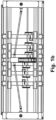
- the Figures 1a to 3c show the tool stamp 1 alone, partly with and partly without the cardboard tubes 100 that are open in terms of their cross section and are to be gripped.
- the tool stamp 1 consists of a frame-shaped base body 2, the largest surface extent of which is the main plane 2 ' - as in the Figures 2a -c marked - defined.
- These gripping rods 1a to 1f, 1A to 1F extend perpendicular to the main plane 2' in the axial direction 10, the Z direction.
- the transverse directions 11a, 11b, the X-direction and Y-direction, which span the main plane 2', are defined in such a way that the first transverse direction 11a or but especially in the main level 2 '.
- the longitudinal center plane 2" perpendicular to the main plane 2' runs in the middle of the extension of the base body 2 in the second transverse direction 11b, the Y direction.
- the base body 2 preferably the entire tool stamp 1 is designed as a mirror image of this long center plane 2".
- the main plane 2' of the base body 2 is generally horizontal, while the main extension direction 1' of the gripping elements or gripping rods and also the longitudinal center plane 2" are vertical.
- the frame-shaped base body 2 consists of two longitudinal struts 15a, which run parallel and at a distance from one another in the first transverse direction 11a and which are connected to one another at their respective analog free ends via a cross strut 15b to form a rectangle, lying parallel to the main plane 2 '.
- one of two traverse guides 13a, b is present on both sides, which also run in the X direction and are also firmly connected with their ends to one of the cross struts 15b.
- the spindle nuts 7a of all crossbars 5 rotate about the same axis of rotation, which runs parallel to the first transverse direction 11a.
- a non-rotatable threaded rod 7b which is fastened with its ends in the cross struts 15b and is in engagement with the spindle nuts 7a, extends along this axis of rotation, so that each cross member 5 is independent of the others by controlled drive of the individual motors 6a of the X-drives 6 - except for the fact that mutual overtaking in the X direction is not possible - it can be moved back and forth in the X direction within the movement range 1".
- Two gripping rods extend from each of the crossbars 5 - spaced apart from one another in the Y direction - downwards, i.e. in the axial direction 10, the Z direction.
- the two gripping rods 1f, 1F per crossbar 5 are movable relative to one another in the of the base body 2.
- each of the gripping rods 1f, 1F is attached at its upper end to a guide sleeve 9, which is movable in the Y direction relative to the cross strut 5.
- Each of the guide sleeves 9 has a through opening running in the a rod which runs through the through opening in the guide sleeves 9 and fits exactly into it, so that each guide sleeve 9 can be moved along one of the X-guides 3a, b.
- the X-guides 3a, b are round rods and the through openings of the guide sleeves 9 also have a matching round cross section.
- the X-guides 3a, b are fastened with their free ends in the cross struts 15d of the base body 2, but only fixed in the one of the cross struts 15b is housed, movable in counter-synchrony with one another.
- the twelve gripping rods in this case are thus divided into two displacement groups 1.1, 1.2:
- One half of the gripping rods 1a-1f is the displacement group 1.1 which is arranged in the identical Y position and is located in one end region of their respective Cross struts 5 are located, while the other half of the gripping rods 1A to 1F occupies a spaced-apart displacement group 1.2, but within the displacement group 1.2, a different Y position on the opposite side of the longitudinal center plane 2 "and these gripping rods 1A to 1F located in the other end region of their respective crossbars 5.
- FIG. 4c is shown enlarged in perspective, can be taken by starting from that in the Figures 2a -c shown state, the entire tool stamp 1 is lowered and thereby a specific gripping group of gripping bars is inserted into a cardboard sleeve 100 and then by moving the individual gripping bars in the X and Y directions along the base body 2 of the tool stamp 1 with respect to the cross-sectional center of the respective cardboard sleeve 100, the cardboard sleeve 100 is clamped to a free inner cross section 100 ', in particular by extending the gripping rods of the gripping group into the inner corners of the cross section 100' of the cardboard sleeve 100 in the main plane 2' until they have such a contact force on the inner surface 103 of the cardboard sleeve 100 rests so that the cardboard sleeve has a force fit on this gripping group is held by gripping rods and by moving, in particular raising and moving to the side, the entire tool stamp 1, the one or more cardboard tubes 100 held
- one or more cardboard tubes 100 can be gripped at the same time: For gripping a cardboard tube 100 with a rectangular cross section - as in Figure 3a shown - only one gripping group consisting of four gripping rods 1a, 1A, 1b, 1B arranged in a rectangle is required, so that by means of the existing twelve gripping rods 1a to 1f, 1A to 1F, which are arranged in two displacement groups 1.1, 1.2, simultaneously up to three cardboard tubes 100 with a rectangular cross-section can be handled, provided that their cross-sections are small enough to be able to arrange these three vertically extending cardboard tubes 100 next to each other, i.e. in a row extending in the X direction, within the movement range 1 "below the gripping bars.
- Such an open cardboard tube - as in Figure 4c shown - has, on the one hand, a sleeve body 104, consisting of the four side walls 100a-d which adjoin one another in the circumferential direction around the free cross section and are connected to one another in an articulated manner.
- a sleeve body 104 At the lower end 104a of the sleeve body 104 - preferably aligned with the respective side wall 100a-d of the sleeve body 104, i.e. running vertically - there is a lower pivot tab 105a-d, from which the base 106 is later formed by pivoting inwards and gluing against each other boxes to be produced from the cardboard tube.
- each side wall 100a-d is usually adjoined at the upper end by such a pivoting tab 105a-d, from which a closed top of the box is later created only after the box has been filled.
- such an open cardboard tube 100 therefore has a free inner cross section 100 'continuous from the upper open side 101 to the lower open side 102, into which the gripping rods can be inserted from above, preferably until the lower one free end of the gripping rods - which are preferably all at the same height in the Z direction - are at the level of the lower end of the cardboard body 104 or just above.
- the gripping rods have a rectangular, preferably square, cross-section, with which cardboard tubes 100 with a rectangular inner cross-section or with inner cross-sections whose inner corners each have an inner angle of at least 90 ° can be clamped and gripped in the main plane 2 '.
- the gripping rods could also have an external cross section in the form of a right-angled triangle.
- an equilateral triangle can also be chosen - as in Figure 3b shown at the top left - or a triangular shape in which the triangle angle at one corner of the triangle is less than 60 °, which means that even smaller internal angles could be approached in a cardboard tube 100, as can occur, for example, in a triangular cardboard tube.
- the length of the gripping rods is designed for the longest axial length of cardboard tubes 100 that can be handled.
- the base body 2 is at a relatively large distance above the upper end of the Cardboard tubes 100.
- this additional cross member 5' is only located in the free distance between the two gripping rods to be supported, this additional cross member 5' can also be retracted into the inner free cross section 100' of the cardboard tube 100 when gripping cardboard tubes 100.
- the gripping rod at the upper end can be pivoted relative to the guide sleeve 9 about a pivot axis 17, which lies parallel to the main plane 2 'at an angle to the X and Y directions that is adapted to the cross-sectional shape of the cardboard sleeve to be gripped, and preferably the gripping rod itself is pivotable about the Z direction.
- a contact element can - especially in this case - be placed at at least one point on the outer circumference of the gripping bar 18 can be arranged, which can be moved not only in the axial direction along the gripping rod, but also relative to it about a further pivot axis 17', preferably parallel to the pivot axis 17, in any case at least around a further pivot axis 17' lying transversely to the Z direction, preferably in the main plane 2 '. be pivotable.
- the contact element 18 has an outer contour which is suitable for resting on the inner contour of the cardboard tube to be gripped, preferably in one of its inner corners, preferably in the form of an angle profile, as in Figure 3b shown below left.
- round cardboard tubes can also be gripped, as in Figure 3b shown on the far right by sliding a contact element 18 onto a gripping rod with a polygonal, for example square, cross-section, which has an outer contour in the form of a circular segment, the radius of curvature of which is equal to or slightly smaller than the radius of curvature of the circular inner circumferential contour of the cardboard tube 100 to be gripped.
- a polygonal, for example square, cross-section which has an outer contour in the form of a circular segment, the radius of curvature of which is equal to or slightly smaller than the radius of curvature of the circular inner circumferential contour of the cardboard tube 100 to be gripped.
- Fig. 2a show the Fig. 2b the case that two cardboard tubes arranged next to one another - again rectangular in cross section - are gripped by the tool stamp 1 at the same time, but the dimensions of the cross section of this type of cardboard tube are so large that in the first transverse direction 11a, the X direction of the tool stamp 1 , only two such cardboard tubes 100 a, b can be arranged within the movement range 1" of the gripping elements, i.e. here the gripping rods.
- the four gripping rods that are not required can also be arranged in pairs - for example because there is not enough space available for the aforementioned arrangement - inside the free cross section 100 'of one of the two cardboard tubes 100a, b, as in Fig.
- a gripping group for gripping the cardboard sleeve 100a consists of the six gripping bars, for example 1a - 1c and 1A - 1C, although after immersion in the cardboard sleeve 100a, preferably only the four outer gripping bars 1a, 1A, 1c, 1C are in the gripping position, i.e outwards into the inner corners of the rectangular cardboard tube 100, while the two middle gripping rods 1b, B preferably remain in their initial position.
- the gripping group to be lowered into the free inner cross section 100 'of this cardboard sleeve 100 can also include all 12 gripping bars 1a - f, 1A - F, whereby after lowering into the cardboard sleeve 100 only preferably the outer four gripping bars 1a, A, 1f, F can be extended into the gripping position, i.e. into the inner corners of the rectangular free cross section 100' of the cardboard tube 100 in the main plane 2'.
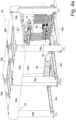
- FIG. 4a the entire handling device 30 is shown, including the supporting frame 34 consisting of the vertical posts 34a, which are connected at the upper end by upper horizontal traverses 34b running in both horizontal directions, and at the lower end by preferably also in both horizontal directions -Lower horizontal trusses 34c running in different directions.
- this frame 34 is in Fig. 4b , which however depicts a slightly different work situation, is omitted.
- the handling device 30 includes: On the one hand, the box opener 40, which removes the last one from a supply stack 51 of flat-folded boxes 99 - as shown in the Fig. 7a - c explained - and at a defined gripping position in the open state, i.e. as an open cardboard tube 100, for gripping by the tool stamp 1, as in the Fig. 2a - c shown.
- the box opener 40 which removes the last one from a supply stack 51 of flat-folded boxes 99 - as shown in the Fig. 7a - c explained - and at a defined gripping position in the open state, i.e. as an open cardboard tube 100, for gripping by the tool stamp 1, as in the Fig. 2a - c shown.
- the tool stamp 1 is lifted here by means of a lifting device 35 in the form of a scissor linkage 35, which engages at its lower end on the base body 2 of the tool stamp 1, and is fastened at its upper end to a carriage 32, which runs along guides 33 in the form of Rails can be moved in the and lowered, for example also placed on the ground.
- a lifting device 35 in the form of a scissor linkage 35, which engages at its lower end on the base body 2 of the tool stamp 1, and is fastened at its upper end to a carriage 32, which runs along guides 33 in the form of Rails can be moved in the and lowered, for example also placed on the ground.
- a controller 30 controls all movements of all movable parts of the handling device 30, including those of the tool stamp 1.
- FIG. 4a shows the tool stamp 1 in the waiting position so that the cardboard erector 40 provides a new set of open, graspable cardboard tubes 100 Fig. 5a in the side view the state while the gripping groups of gripping elements 1a - f, A - F are just being lowered into the three open cardboard tubes 100a - c provided next to each other by lowering the tool stamp 1.
- Fig. 4b shows one step further the movement of the tool stamp 1 by means of the movement device 31 in the X direction with the three cardboard tubes 100a - c hanging on it and gripped by the tool stamp 1.
- Fig. 6a shows how the tool stamp 1 has already moved the three cardboard sleeves 100a, b, c over the beginning of the base closing device 20 and places them on their rail-shaped counterholder 21 with their already closed bases 106, and these are currently being glued.
- the gripping elements 1a - 1F are preferably moved further down in the Z direction until they press on the top of the swivel tabs 105a, b located above and thus open the adhesive spots preferably applied underneath.
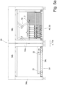
- the front view of the Fig. 5b shows the same situation as Fig. 5a in the viewing direction X, in which the gripping elements of the tool stamp 1 move straight into the cardboard tubes 100a - c.
- Fig. 5b and Fig. 6b So show in the front view of the handling device 30, on the one hand, the gripping of the cardboard tubes 100 and, on the other hand, the placing of their bottoms 106.
- the lifting device 35 here in the form of the scissor linkage 35, is designed to be movable in a controlled manner along the carriage 32 in the Y direction, and thus the carriage 1 not only in the X and Z directions, but also in the Y direction.
- Direction can be designed to be movable to a limited extent.
- the inclined surface 43 can also be seen, which usually extends outside the frame 34 of the handling device 30, and on which the supply stack 51 of essentially upright, adjacent, flat-folded cardboard tubes 99 automatically slides into place
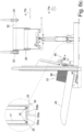
- Direction of the box opener 40 which enlarges in the Fig. 7a - c is shown in different functional positions: This shows Fig.
- both positions of the box opener 40 Since in this case three cardboard tubes 100a, b, c, next to each other are to be gripped simultaneously by the tool stamp 1, the cardboard opener 40 in this case comprises three opening units 44, which are arranged in the X direction along two guide rods arranged one above the other at a distance parallel to one another 45a, b of an X-guide 45 can be moved and adjusted so that they are in the in Fig. 7a
- the docking position shown at the top right is in the correct places on the first flat-folded cardboard tubes 99 of the in Fig. 7c
- the more easily recognizable supply stack 51 which consists of three adjacent partial supply stacks, can dock.
- the opening units 44 move into the offering position Fig. 7a shown further to the left and slightly lower by moving the X-guide 45 along a Y-guide 46.
- the suction units 47 which are not completely vertical in the docking position but are slightly at an angle to the vertical, are pivoted into the vertical position in accordance with the inclination of the flat-folded cardboard sleeves 99 resting with their lower edge on the inclined surface 43, so that the now open cardboard sleeves 100 a - c held by the opening unit 44 are now vertical in the offering position.
- the offering position is already part of the gripping station 50, because in this offering position the gripping rods are inserted from above into the inner free cross section 100' of the open cardboard tubes 100.
- the two vertical struts which connect the two guide rods 45a, b at the ends and can be moved with their lower end in the Y-guide 46, can be pivoted about a pivot axis running parallel to the X-axis.
- Each suction unit 47 consists of a plate, on the front of which there are two or more suction cups 41 one above the other in order to suck on the outer surface of one of the side walls 100.1 facing them.
- the adjacent side walls 100.1 and 100.2 are pressed into a perpendicular position to one another, and the cardboard sleeve now has its open, rectangular, free inner cross section 100 ', as required for inserting the holding rods into the gripping station 50.
Landscapes
- Engineering & Computer Science (AREA)
- Mechanical Engineering (AREA)
- Making Paper Articles (AREA)
- Manipulator (AREA)
Claims (10)
- Dispositif de manutention (30) pour saisir et maintenir des cosses de carton (100) ouvertes des deux côtés dans le sens axial (10), avec- une commande (30'),- au moins un outil de poinçonnage (1) avec un corps de base (2) et des membres de saisie (1a - f, 1A - F) qui sont fixés de manière mobile au corps de base (2),- dans lequel le corps de base (2) présente sa plus grande extension de surface dans son plan principal (2'),- dans lequel les membres de saisie (1a - f, 1A - F) ont un sens principal d'extension (1'), où ils ont leur plus grande dimension, qui s'étend transversalement au plan principal (2') du corps de base (2) et- les membres de saisie (1a - f, 1A - F), en particulier tous, s'étendent à partir du corps de base (2) vers le même côté, en particulier vers le bas,
caractérisé en ce que- les membres de saisie (1a - f, 1A - F) peuvent être déplacés par rapport au corps de base (2) dans les deux sens transversaux (11a, b) du plan principal (2') du corps de base (2) qui sont perpendiculaires l'une à l'autre,- le dispositif de manutention est conçu de telle sorte que les membres de saisie, après avoir été introduits dans la cosse de carton, peuvent être amenés dans une position finale dans laquelle ils s'appliquent contre la surface intérieure de la cosse de carton et maintiennent celui-ci par adhérence de force,- un premier rang de membres de saisie (1a - f) peut être déplacé de manière commandée en tant que premier groupe déplaçable (1.1) le long d'un premier guidage X (3a) qui s'étend dans le premier sens transversal (11a) et un deuxième rang de membres de saisie (1A - F) peut être déplacé de manière commandée en tant que deuxième groupe déplaçable (1.2) le long d'un deuxième guidage X (3b) qui lui est parallèle, et- au moins un, en particulier les deux, guidages X (3a, b) sont guidés à leurs extrémités respectivement dans un guidage Y (4a, b) qui s'étend dans le deuxième sens transversal (11b) et peuvent être déplacés de manière commandée à leur distance mutuelle, et- les deux groupes déplaçables (1.1, 1.2) possèdent chacun le même nombre de membres de saisie (1a - f, 1A - F) et un membre de saisie (1a) respectif sur l'un des guidages X (3a) est relié à un membre de saisie (1A) situé en face sur l'autre guidage X (3b) par l'intermédiaire d'une traverse (5) de manière fixe dans le sens X et de manière mobile l'un par rapport à l'autre dans le sens Y,- chaque traverse (5) peut être déplacée dans le sens X par l'intermédiaire d'un entraînement X (6) indépendamment des autres traverses (5),- les deux guidages X (3a, b) sont déplacés dans leur distance relative le long des guidages Y (4a, b) au moyen d'un entraînement Y (8) avec un moteur central (8a),- la commande (30') est apte à positionner les membres de saisie (1a - f, 1A - F) de manière à former des groupes de saisie, de sorte que chaque groupe de saisie puisse être introduit axialement dans l'une des cosses de carton (100) à saisir. - Dispositif selon la revendication 1,
caractérisé en ce que- les membres de saisie (1a - f, 1A - F) sont des barres ou des tubes droits et/ou- les membres de saisie (1a - f, 1A - F) présentent, au moins sur une partie de leur extension, une circonférence extérieur polygonale, en particulier rectangulaire, en particulier carrée, transversalement à leur sens principal d'extension (1'). - Dispositif selon l'une des revendications de dispositif précédentes,
caractérisé en ce que- le corps de base (2) présente, dans au moins l'un des sens transversaux (11a, b) du plan principal (2'), une extension plus grande que la région de mouvement (1") dans laquelle les outils de poinçonnage (1) peuvent se déplacer dans le plan principal (2') et/ou à la section transversale intérieure libre (100') de la plus grande cosse de carton (100) à gérer. - Dispositif selon l'une des revendications de dispositif précédentes,
caractérisé en ce que- entre les deux membres de saisie (1a, A) reliés entre eux de manière fixe dans le sens X et mobile l'un par rapport à l'autre dans le sens Y par l'intermédiaire d'une traverse (5), il existe une autre traverse (5') espacée dans le sens axiale Z, la perpendiculaire au plan principal (2') du corps de base (2), dont la distance Z par rapport à la première traverse (5) est réglable de manière commandée, et/ou- les deux guidages X (3a, b) sont déplacés dans leur distance relative le long des guidages Y (4a, b) de manière synchrone en sens opposé au plan longitudinal central (2") dans le plan principal (2') du corps de base (2). - Dispositif selon l'une des revendications de dispositif précédentes,
caractérisé en ce que- chaque traverse (5) est entraînée au moyen d'un écrou de broche (7a) disposé sur la traverse (5), entraîné par un moteur (6a), qui est en prise avec une tige filetée (7b) qui s'étend parallèlement aux guidages X (3a, b) et qui est fixée en rotation par ses extrémités dans le corps de base (2). - Dispositif selon l'une des revendications de dispositif précédentes,
caractérisé en ce que- sur chacun des membres de saisie (1a - f, 1A - F) est arrangé au moins un élément de contact (18) pour entrer en contact avec la surface intérieure (103) de la cosse (100), lequel est fixé au membre de saisie (1a - f, 1A - F) en particulier de manière pivotante, en particulier autour d'un axe de pivotement (17') transversal au sens axial (10). - Dispositif selon l'une des revendications de dispositif précédentes,
caractérisé en ce que- les mouvements des membres de saisie (1a - f, 1A - F) contre la surface intérieure (103) de la cosse (100), en particulier les moteurs entraînants (6a, 8a), sont commandés par la force et sont opérés jusqu'à ce qu'une force prédéfinie soit atteinte par le moteur correspondant (6a, 8a), la force étant en particulier prédéfinie sous forme d'une intensité de courant prédéfinie. - Dispositif selon l'une des revendications de dispositif précédentes,
caractérisé en ce que- un dispositif de déplacement (31) est présent, qui est capable de déplacer ledit au moins un outil de poinçonnage (1) dans le sens axial (10) et dans au moins un des sens transversaux (11a, b), et où en particulier
soit le dispositif de déplacement (31)- comprend un coulisseau (32) comprenant le corps de base (2) de l'outil de poinçonnage (1) et qui peut être déplacé le long de guidages horizontaux (33), en particulier de rails (33), en particulier dans l'un des sens transversaux (11a, b) et- comprend un dispositif de levage (35) entre le coulisseau (32) et l'outil de poinçonnage (1), en particulier son corps de base (2), afin de déplacer l'outil de poinçonnage (1) dans le sens axial (10), en particulier dans le sens verticale, et- en particulier l'outil de poinçonnage (1) peut être déplacé de manière commandée sur le coulisseau (32) dans l'autre sens transversal (11b, a) ou
soit le dispositif de déplacement (31) est un bras de robot. - Dispositif selon l'une des revendications de dispositif précédentes, caractérisé en ce que- le dispositif comprend un ouvreur de carton (40) pour étirer les cosses de carton (99) pliés à plat pour former des cosses de carton (100) ouvertes dans la section transversale, et en particulier
l'ouvreur de carton (40)- comprend une première unité d'aspirateur (47) avec au moins un aspirateur (41), qui est capable de saisir la cosse de carton (99) plié à plat sur une première surface latérale (100.1) et de la retirer d'une pile de stockage (51) de cosses de carton (99) pliés à plat, ainsi que- un volet d'ouverture (42) adjacent à l'unité d'aspirateur (47), qui est pivotable de manière commandée autour d'un axe de pivotement, qui est parallèle aux bords de la future cosse de carton (100) et qui est capable de plier la deuxième surface (100.2) de la cosse de carton (100), adjacente à la première surface latérale (100.1) et située dans le même plan à l'état plié à plat, dans une position angulaire, en particulier à angle droit, par rapport à celle-ci, et d'ouvrir ainsi la cosse de carton (100). - Dispositif selon l'une des revendications de dispositif précédentes,
caractérisé en ce que
il existe un dispositif de fermeture de fond (20) comprenant :- un contre-support (21) s'étendant dans le premier sens transversal (11a) pour déposer ou pousser les fonds (106) des cosses de carton (100) supportés par l'outil de poinçonnage (100),- deux membres de guidage (23) s'étendant dans le premier sens transversal (11a), en particulier fixes, pour plier les pattes de pivotement (105 a, b) s'étendant dans ce sens transversal (11a) dans un plan transversal (11') par rapport au sens axial (10) par un mouvement de contact le long des membres de guidage (23),- au moins un membre de pliage (24) mobile et entraîné de manière commandée, pour plier les pattes de pivotement (105 c, d) s'étendant dans le deuxième sens transversal (11b), pour plier les pattes de pivotement (105 c, d) s'étendant dans ce sens transversale (11b) dans un plan transversal (11') par rapport au sens axial (10) et pour les appuyer contre la surface de fond des deux premières pattes de pivotement (105 a, b) déjà pliées,- un applicateur de colle (22) pour appliquer une colle (25) entre les deux couches de pattes pivotantes (105a - d) pliées et empilées.
Applications Claiming Priority (1)
| Application Number | Priority Date | Filing Date | Title |
|---|---|---|---|
| DE102015122901.3A DE102015122901B4 (de) | 2015-12-29 | 2015-12-29 | Vorrichtung und Verfahren zum Ergreifen und Transportieren von RSC-Kartons |
Publications (3)
| Publication Number | Publication Date |
|---|---|
| EP3187427A1 EP3187427A1 (fr) | 2017-07-05 |
| EP3187427B1 EP3187427B1 (fr) | 2018-11-14 |
| EP3187427B2 true EP3187427B2 (fr) | 2023-11-01 |
Family
ID=57354221
Family Applications (1)
| Application Number | Title | Priority Date | Filing Date |
|---|---|---|---|
| EP16199590.7A Active EP3187427B2 (fr) | 2015-12-29 | 2016-11-18 | Dispositif et procédé destinés à saisir et à transporter des cartons rsc |
Country Status (2)
| Country | Link |
|---|---|
| EP (1) | EP3187427B2 (fr) |
| DE (1) | DE102015122901B4 (fr) |
Families Citing this family (6)
| Publication number | Priority date | Publication date | Assignee | Title |
|---|---|---|---|---|
| DE102018110639A1 (de) * | 2018-05-03 | 2019-11-07 | Krones Aktiengesellschaft | Verfahren und Vorrichtung zum Verschließen von Karton-Umverpackungen |
| CN108674946B (zh) * | 2018-07-26 | 2023-10-13 | 济南速雕数控机械有限公司 | 一种家具板材的卸料转移装置 |
| CN109397742B (zh) * | 2018-11-30 | 2024-01-26 | 中天智能装备有限公司 | 一种纸盒自动封盖机构 |
| CN109533490B (zh) * | 2018-12-27 | 2023-06-23 | 南京工程学院 | 一种磁吸式自动套袋机及其使用方法 |
| CN110451028B (zh) * | 2019-09-11 | 2021-09-28 | 绥宁县吉升工业纸板有限责任公司 | 一种纸箱打包机 |
| CN113334854B (zh) * | 2021-07-06 | 2024-08-13 | 鹤山市联兴纸制品有限公司 | 纸板导料压痕方法 |
Family Cites Families (21)
| Publication number | Priority date | Publication date | Assignee | Title |
|---|---|---|---|---|
| US2718426A (en) | 1952-12-08 | 1955-09-20 | Nagy James | Block lifting and loading apparatus |
| US3465499A (en) * | 1966-08-01 | 1969-09-09 | Hoerner Waldorf Corp | Bag opening apparatus |
| FR2116290B1 (fr) | 1970-12-04 | 1975-01-10 | Barbier Roger | |
| DE2445177C2 (de) | 1974-09-21 | 1987-06-25 | Schaberger Carlo Sondermasch | Greifvorrichtung zum erfassen und umsetzen von zeilenweise aufgereihten behaeltnissen, wie flaschen, dosen oder dergleichen |
| NL8702044A (nl) * | 1987-08-31 | 1989-03-16 | Overveld B V Maschf Van | Dozenuitvouwmachine. |
| US5116094A (en) | 1989-03-14 | 1992-05-26 | The Boeing Company | Apparatus and method for handling honeycomb core |
| JPH0683981B2 (ja) | 1989-04-13 | 1994-10-26 | 東レエンジニアリング株式会社 | チャック装置 |
| DE4122953A1 (de) * | 1991-07-11 | 1993-01-14 | Nahrungsguetermaschbau Gmbh | Vorrichtung zum aufnehmen und freigeben von stueckguetern |
| US6013438A (en) | 1996-11-27 | 2000-01-11 | Baylor College Of Medicine | Assay for detecting apoptotic cells |
| DE29907459U1 (de) * | 1999-04-27 | 1999-07-29 | Norden Pac Development Ab, Kalmar | Verpackungsmaschine |
| ITBO20000659A1 (it) | 2000-11-14 | 2002-05-14 | Oma Srl | Testa sfaldatrice per macchine depallettizzatrici |
| JP3968415B2 (ja) | 2001-11-30 | 2007-08-29 | 独立行政法人産業技術総合研究所 | 把持装置 |
| ITPR20050070A1 (it) * | 2005-11-16 | 2007-05-17 | P E Promec Sistemi Srl | Apparato per formare contenitori di cartone. |
| DE102008010432A1 (de) | 2008-02-21 | 2009-08-27 | Focke & Co.(Gmbh & Co. Kg) | Verfahren und Vorrichtung zum Einführen von (Schlauch-)Beuteln in Kartons |
| WO2011050112A2 (fr) | 2009-10-20 | 2011-04-28 | Nexus Biosystems, Inc. | Appareil de préhension et procédé pour des contenants de différentes tailles |
| US8172292B1 (en) | 2009-11-04 | 2012-05-08 | SACMI USA, Ltd. | Arm tool for packing trays in boxes |
| US8973735B2 (en) * | 2011-09-19 | 2015-03-10 | The Procter & Gamble Company | Mechanisms for transferring items |
| CN202278586U (zh) | 2011-09-28 | 2012-06-20 | 巨石集团有限公司 | 一种取放用机械手抓 |
| DE102012220294A1 (de) | 2012-11-07 | 2014-05-08 | IBG-Automation GmbH | Greifvorrichtung und Verfahren zur Betätigung eines Werkstücks |
| DE202014001939U1 (de) | 2014-02-28 | 2015-05-29 | Liebherr-Verzahntechnik Gmbh | Handhabungsvorrichtung |
| DE102014221221A1 (de) | 2014-10-20 | 2016-04-21 | Krones Aktiengesellschaft | Vorrichtung und Verfahren zum Aufziehen und Aufrichten von zusammengelegten oder zusammengefalteten Kartonagen zu stehend angeordneten Gefachen und/oder Umverpackungen |
-
2015
- 2015-12-29 DE DE102015122901.3A patent/DE102015122901B4/de active Active
-
2016
- 2016-11-18 EP EP16199590.7A patent/EP3187427B2/fr active Active
Non-Patent Citations (2)
| Title |
|---|
| IMOVE ENTERPRISES: "Palletizing Robot Freeze trays3 PARO by roTeg", YOUTUBE, 13 October 2011 (2011-10-13), Retrieved from the Internet <URL:https://www.youtube.com/watch?v=VW8wU7EClHg> † |
| ROTEG PALETTIERROBOTER: "Palettierroboter PARO für Trays", YOUTUBE, 24 August 2009 (2009-08-24), Retrieved from the Internet <URL:https://www.rateg.de/traypalettierung> † |
Also Published As
| Publication number | Publication date |
|---|---|
| EP3187427B1 (fr) | 2018-11-14 |
| DE102015122901B4 (de) | 2018-06-14 |
| EP3187427A1 (fr) | 2017-07-05 |
| DE102015122901A1 (de) | 2017-06-29 |
Similar Documents
| Publication | Publication Date | Title |
|---|---|---|
| EP3187427B2 (fr) | Dispositif et procédé destinés à saisir et à transporter des cartons rsc | |
| EP0491658B1 (fr) | Procédé et dispositif pour déformer sous forme d'ondulation un matériau en feuilles | |
| EP3144255A1 (fr) | Dispositif destine a reconditionner des marchandises au detail regroupees en emballages unitaires | |
| DE69003391T2 (de) | Pressenstrasseanordnung. | |
| DE10359310A1 (de) | Vorrichtung und Verfahren zur Herstellung von Behälterverpackungen | |
| EP0672480A1 (fr) | Système de transport | |
| EP3825262B1 (fr) | Station de retournement pour panneaux en tôle ou piles de panneaux en tôle et procédé d'utilisation de la station de retournement | |
| EP3595827B1 (fr) | Dispositif de centrage | |
| EP0671228A2 (fr) | Installation de transport pour pièces à usiner dans une presse | |
| DE102014102333A1 (de) | Vorrichtung und Verfahren zur Vorfaltung von Packungsmänteln | |
| EP4112513B1 (fr) | Système doté d'un dispositif d'appréhension | |
| DE19904443A1 (de) | Verfahren und Vorrichtung zum Zuführen von Packungszuschnitten | |
| DE4216123A1 (de) | Formatveränderbare Stapelstation für aufeinanderfolgend angelieferte Blatterzeugnisse | |
| EP3576932B1 (fr) | Dispositif de manipulation et procédé de fermeture de languettes de fond extérieures d'un suremballage | |
| EP4007664B1 (fr) | Procédé de transfert, système de manipulation conçu pour celui-ci, et unité de pliage | |
| WO2018055178A1 (fr) | Procédé et machine-outil servant à l'usinage de pièces en forme de plaque, en particulier de tôles | |
| DE69601510T2 (de) | Vorrichtung zum Entnehmen und Aufrichten von schlauchförmigen Zuschnitten, in Kartoniermaschinen und dergleichen | |
| DE102008001346A1 (de) | Kartonaufrichter | |
| WO2017025221A1 (fr) | Procédé permettant de déplacer au moins un dispositif de manutention conçu pour la manipulation de produits en vrac, et dispositif de manipulation de produits en vrac | |
| DE9405299U1 (de) | Vorrichtung zum Auffalten von Kisten | |
| EP4159388B1 (fr) | Dispositif doté d'un préhenseur | |
| DE3936764C2 (fr) | ||
| EP4107103B1 (fr) | Séparateur de découpes, machine d'emballage, et procédé de réalisation de découpes individualisées à partir d'une pile | |
| DE2719338A1 (de) | Verfahren und vorrichtung zur herstellung von behaeltern, boden- und deckelteilen aus flachmaterial | |
| DE102022103779B4 (de) | Verfahren zum Umsetzen von Produkten sowie hierfür geeigneter Umsetz-Roboter |
Legal Events
| Date | Code | Title | Description |
|---|---|---|---|
| PUAI | Public reference made under article 153(3) epc to a published international application that has entered the european phase |
Free format text: ORIGINAL CODE: 0009012 |
|
| STAA | Information on the status of an ep patent application or granted ep patent |
Free format text: STATUS: THE APPLICATION HAS BEEN PUBLISHED |
|
| AK | Designated contracting states |
Kind code of ref document: A1 Designated state(s): AL AT BE BG CH CY CZ DE DK EE ES FI FR GB GR HR HU IE IS IT LI LT LU LV MC MK MT NL NO PL PT RO RS SE SI SK SM TR |
|
| AX | Request for extension of the european patent |
Extension state: BA ME |
|
| STAA | Information on the status of an ep patent application or granted ep patent |
Free format text: STATUS: REQUEST FOR EXAMINATION WAS MADE |
|
| 17P | Request for examination filed |
Effective date: 20170707 |
|
| RBV | Designated contracting states (corrected) |
Designated state(s): AL AT BE BG CH CY CZ DE DK EE ES FI FR GB GR HR HU IE IS IT LI LT LU LV MC MK MT NL NO PL PT RO RS SE SI SK SM TR |
|
| REG | Reference to a national code |
Ref country code: DE Ref legal event code: R079 Ref document number: 502016002504 Country of ref document: DE Free format text: PREVIOUS MAIN CLASS: B65B0043340000 Ipc: B65B0061020000 |
|
| GRAP | Despatch of communication of intention to grant a patent |
Free format text: ORIGINAL CODE: EPIDOSNIGR1 |
|
| STAA | Information on the status of an ep patent application or granted ep patent |
Free format text: STATUS: GRANT OF PATENT IS INTENDED |
|
| INTG | Intention to grant announced |
Effective date: 20180727 |
|
| RIC1 | Information provided on ipc code assigned before grant |
Ipc: B65B 43/26 20060101ALI20180718BHEP Ipc: B65B 43/12 20060101ALI20180718BHEP Ipc: B65B 61/02 20060101AFI20180718BHEP Ipc: B65B 41/18 20060101ALI20180718BHEP |
|
| GRAS | Grant fee paid |
Free format text: ORIGINAL CODE: EPIDOSNIGR3 |
|
| GRAA | (expected) grant |
Free format text: ORIGINAL CODE: 0009210 |
|
| STAA | Information on the status of an ep patent application or granted ep patent |
Free format text: STATUS: THE PATENT HAS BEEN GRANTED |
|
| AK | Designated contracting states |
Kind code of ref document: B1 Designated state(s): AL AT BE BG CH CY CZ DE DK EE ES FI FR GB GR HR HU IE IS IT LI LT LU LV MC MK MT NL NO PL PT RO RS SE SI SK SM TR |
|
| REG | Reference to a national code |
Ref country code: CH Ref legal event code: EP Ref country code: AT Ref legal event code: REF Ref document number: 1064515 Country of ref document: AT Kind code of ref document: T Effective date: 20181115 |
|
| REG | Reference to a national code |
Ref country code: DE Ref legal event code: R096 Ref document number: 502016002504 Country of ref document: DE |
|
| REG | Reference to a national code |
Ref country code: IE Ref legal event code: FG4D Free format text: LANGUAGE OF EP DOCUMENT: GERMAN |
|
| REG | Reference to a national code |
Ref country code: NL Ref legal event code: MP Effective date: 20181114 |
|
| REG | Reference to a national code |
Ref country code: LT Ref legal event code: MG4D |
|
| PG25 | Lapsed in a contracting state [announced via postgrant information from national office to epo] |
Ref country code: ES Free format text: LAPSE BECAUSE OF FAILURE TO SUBMIT A TRANSLATION OF THE DESCRIPTION OR TO PAY THE FEE WITHIN THE PRESCRIBED TIME-LIMIT Effective date: 20181114 Ref country code: HR Free format text: LAPSE BECAUSE OF FAILURE TO SUBMIT A TRANSLATION OF THE DESCRIPTION OR TO PAY THE FEE WITHIN THE PRESCRIBED TIME-LIMIT Effective date: 20181114 Ref country code: LV Free format text: LAPSE BECAUSE OF FAILURE TO SUBMIT A TRANSLATION OF THE DESCRIPTION OR TO PAY THE FEE WITHIN THE PRESCRIBED TIME-LIMIT Effective date: 20181114 Ref country code: IS Free format text: LAPSE BECAUSE OF FAILURE TO SUBMIT A TRANSLATION OF THE DESCRIPTION OR TO PAY THE FEE WITHIN THE PRESCRIBED TIME-LIMIT Effective date: 20190314 Ref country code: FI Free format text: LAPSE BECAUSE OF FAILURE TO SUBMIT A TRANSLATION OF THE DESCRIPTION OR TO PAY THE FEE WITHIN THE PRESCRIBED TIME-LIMIT Effective date: 20181114 Ref country code: BG Free format text: LAPSE BECAUSE OF FAILURE TO SUBMIT A TRANSLATION OF THE DESCRIPTION OR TO PAY THE FEE WITHIN THE PRESCRIBED TIME-LIMIT Effective date: 20190214 Ref country code: LT Free format text: LAPSE BECAUSE OF FAILURE TO SUBMIT A TRANSLATION OF THE DESCRIPTION OR TO PAY THE FEE WITHIN THE PRESCRIBED TIME-LIMIT Effective date: 20181114 Ref country code: NO Free format text: LAPSE BECAUSE OF FAILURE TO SUBMIT A TRANSLATION OF THE DESCRIPTION OR TO PAY THE FEE WITHIN THE PRESCRIBED TIME-LIMIT Effective date: 20190214 |
|
| PG25 | Lapsed in a contracting state [announced via postgrant information from national office to epo] |
Ref country code: RS Free format text: LAPSE BECAUSE OF FAILURE TO SUBMIT A TRANSLATION OF THE DESCRIPTION OR TO PAY THE FEE WITHIN THE PRESCRIBED TIME-LIMIT Effective date: 20181114 Ref country code: GR Free format text: LAPSE BECAUSE OF FAILURE TO SUBMIT A TRANSLATION OF THE DESCRIPTION OR TO PAY THE FEE WITHIN THE PRESCRIBED TIME-LIMIT Effective date: 20190215 Ref country code: NL Free format text: LAPSE BECAUSE OF FAILURE TO SUBMIT A TRANSLATION OF THE DESCRIPTION OR TO PAY THE FEE WITHIN THE PRESCRIBED TIME-LIMIT Effective date: 20181114 Ref country code: PT Free format text: LAPSE BECAUSE OF FAILURE TO SUBMIT A TRANSLATION OF THE DESCRIPTION OR TO PAY THE FEE WITHIN THE PRESCRIBED TIME-LIMIT Effective date: 20190314 Ref country code: SE Free format text: LAPSE BECAUSE OF FAILURE TO SUBMIT A TRANSLATION OF THE DESCRIPTION OR TO PAY THE FEE WITHIN THE PRESCRIBED TIME-LIMIT Effective date: 20181114 Ref country code: AL Free format text: LAPSE BECAUSE OF FAILURE TO SUBMIT A TRANSLATION OF THE DESCRIPTION OR TO PAY THE FEE WITHIN THE PRESCRIBED TIME-LIMIT Effective date: 20181114 |
|
| PG25 | Lapsed in a contracting state [announced via postgrant information from national office to epo] |
Ref country code: DK Free format text: LAPSE BECAUSE OF FAILURE TO SUBMIT A TRANSLATION OF THE DESCRIPTION OR TO PAY THE FEE WITHIN THE PRESCRIBED TIME-LIMIT Effective date: 20181114 Ref country code: PL Free format text: LAPSE BECAUSE OF FAILURE TO SUBMIT A TRANSLATION OF THE DESCRIPTION OR TO PAY THE FEE WITHIN THE PRESCRIBED TIME-LIMIT Effective date: 20181114 Ref country code: CZ Free format text: LAPSE BECAUSE OF FAILURE TO SUBMIT A TRANSLATION OF THE DESCRIPTION OR TO PAY THE FEE WITHIN THE PRESCRIBED TIME-LIMIT Effective date: 20181114 Ref country code: IT Free format text: LAPSE BECAUSE OF FAILURE TO SUBMIT A TRANSLATION OF THE DESCRIPTION OR TO PAY THE FEE WITHIN THE PRESCRIBED TIME-LIMIT Effective date: 20181114 Ref country code: LU Free format text: LAPSE BECAUSE OF NON-PAYMENT OF DUE FEES Effective date: 20181118 |
|
| REG | Reference to a national code |
Ref country code: DE Ref legal event code: R026 Ref document number: 502016002504 Country of ref document: DE |
|
| PLBI | Opposition filed |
Free format text: ORIGINAL CODE: 0009260 |
|
| REG | Reference to a national code |
Ref country code: BE Ref legal event code: MM Effective date: 20181130 |
|
| REG | Reference to a national code |
Ref country code: IE Ref legal event code: MM4A |
|
| PLAX | Notice of opposition and request to file observation + time limit sent |
Free format text: ORIGINAL CODE: EPIDOSNOBS2 |
|
| PG25 | Lapsed in a contracting state [announced via postgrant information from national office to epo] |
Ref country code: RO Free format text: LAPSE BECAUSE OF FAILURE TO SUBMIT A TRANSLATION OF THE DESCRIPTION OR TO PAY THE FEE WITHIN THE PRESCRIBED TIME-LIMIT Effective date: 20181114 Ref country code: SK Free format text: LAPSE BECAUSE OF FAILURE TO SUBMIT A TRANSLATION OF THE DESCRIPTION OR TO PAY THE FEE WITHIN THE PRESCRIBED TIME-LIMIT Effective date: 20181114 Ref country code: SM Free format text: LAPSE BECAUSE OF FAILURE TO SUBMIT A TRANSLATION OF THE DESCRIPTION OR TO PAY THE FEE WITHIN THE PRESCRIBED TIME-LIMIT Effective date: 20181114 Ref country code: MC Free format text: LAPSE BECAUSE OF FAILURE TO SUBMIT A TRANSLATION OF THE DESCRIPTION OR TO PAY THE FEE WITHIN THE PRESCRIBED TIME-LIMIT Effective date: 20181114 Ref country code: EE Free format text: LAPSE BECAUSE OF FAILURE TO SUBMIT A TRANSLATION OF THE DESCRIPTION OR TO PAY THE FEE WITHIN THE PRESCRIBED TIME-LIMIT Effective date: 20181114 |
|
| 26 | Opposition filed |
Opponent name: KRONES AG Effective date: 20190808 |
|
| PG25 | Lapsed in a contracting state [announced via postgrant information from national office to epo] |
Ref country code: SI Free format text: LAPSE BECAUSE OF FAILURE TO SUBMIT A TRANSLATION OF THE DESCRIPTION OR TO PAY THE FEE WITHIN THE PRESCRIBED TIME-LIMIT Effective date: 20181114 Ref country code: IE Free format text: LAPSE BECAUSE OF NON-PAYMENT OF DUE FEES Effective date: 20181118 Ref country code: FR Free format text: LAPSE BECAUSE OF NON-PAYMENT OF DUE FEES Effective date: 20190114 |
|
| PG25 | Lapsed in a contracting state [announced via postgrant information from national office to epo] |
Ref country code: BE Free format text: LAPSE BECAUSE OF NON-PAYMENT OF DUE FEES Effective date: 20181130 |
|
| PLBB | Reply of patent proprietor to notice(s) of opposition received |
Free format text: ORIGINAL CODE: EPIDOSNOBS3 |
|
| PG25 | Lapsed in a contracting state [announced via postgrant information from national office to epo] |
Ref country code: MT Free format text: LAPSE BECAUSE OF FAILURE TO SUBMIT A TRANSLATION OF THE DESCRIPTION OR TO PAY THE FEE WITHIN THE PRESCRIBED TIME-LIMIT Effective date: 20181114 |
|
| PG25 | Lapsed in a contracting state [announced via postgrant information from national office to epo] |
Ref country code: TR Free format text: LAPSE BECAUSE OF FAILURE TO SUBMIT A TRANSLATION OF THE DESCRIPTION OR TO PAY THE FEE WITHIN THE PRESCRIBED TIME-LIMIT Effective date: 20181114 |
|
| PG25 | Lapsed in a contracting state [announced via postgrant information from national office to epo] |
Ref country code: HU Free format text: LAPSE BECAUSE OF FAILURE TO SUBMIT A TRANSLATION OF THE DESCRIPTION OR TO PAY THE FEE WITHIN THE PRESCRIBED TIME-LIMIT; INVALID AB INITIO Effective date: 20161118 Ref country code: CY Free format text: LAPSE BECAUSE OF FAILURE TO SUBMIT A TRANSLATION OF THE DESCRIPTION OR TO PAY THE FEE WITHIN THE PRESCRIBED TIME-LIMIT Effective date: 20181114 Ref country code: MK Free format text: LAPSE BECAUSE OF NON-PAYMENT OF DUE FEES Effective date: 20181114 |
|
| REG | Reference to a national code |
Ref country code: CH Ref legal event code: PL |
|
| PG25 | Lapsed in a contracting state [announced via postgrant information from national office to epo] |
Ref country code: LI Free format text: LAPSE BECAUSE OF NON-PAYMENT OF DUE FEES Effective date: 20191130 Ref country code: CH Free format text: LAPSE BECAUSE OF NON-PAYMENT OF DUE FEES Effective date: 20191130 |
|
| GBPC | Gb: european patent ceased through non-payment of renewal fee |
Effective date: 20201118 |
|
| PG25 | Lapsed in a contracting state [announced via postgrant information from national office to epo] |
Ref country code: GB Free format text: LAPSE BECAUSE OF NON-PAYMENT OF DUE FEES Effective date: 20201118 |
|
| REG | Reference to a national code |
Ref country code: AT Ref legal event code: MM01 Ref document number: 1064515 Country of ref document: AT Kind code of ref document: T Effective date: 20211118 |
|
| PG25 | Lapsed in a contracting state [announced via postgrant information from national office to epo] |
Ref country code: AT Free format text: LAPSE BECAUSE OF NON-PAYMENT OF DUE FEES Effective date: 20211118 |
|
| P01 | Opt-out of the competence of the unified patent court (upc) registered |
Effective date: 20230527 |
|
| PUAH | Patent maintained in amended form |
Free format text: ORIGINAL CODE: 0009272 |
|
| STAA | Information on the status of an ep patent application or granted ep patent |
Free format text: STATUS: PATENT MAINTAINED AS AMENDED |
|
| 27A | Patent maintained in amended form |
Effective date: 20231101 |
|
| AK | Designated contracting states |
Kind code of ref document: B2 Designated state(s): AL AT BE BG CH CY CZ DE DK EE ES FI FR GB GR HR HU IE IS IT LI LT LU LV MC MK MT NL NO PL PT RO RS SE SI SK SM TR |
|
| REG | Reference to a national code |
Ref country code: DE Ref legal event code: R102 Ref document number: 502016002504 Country of ref document: DE |
|
| PGFP | Annual fee paid to national office [announced via postgrant information from national office to epo] |
Ref country code: DE Payment date: 20251029 Year of fee payment: 10 |