EP4007664B1 - Procédé de transfert, système de manipulation conçu pour celui-ci, et unité de pliage - Google Patents
Procédé de transfert, système de manipulation conçu pour celui-ci, et unité de pliage Download PDFInfo
- Publication number
- EP4007664B1 EP4007664B1 EP20767947.3A EP20767947A EP4007664B1 EP 4007664 B1 EP4007664 B1 EP 4007664B1 EP 20767947 A EP20767947 A EP 20767947A EP 4007664 B1 EP4007664 B1 EP 4007664B1
- Authority
- EP
- European Patent Office
- Prior art keywords
- manipulator
- axis
- arm
- manipulator arm
- arms
- Prior art date
- Legal status (The legal status is an assumption and is not a legal conclusion. Google has not performed a legal analysis and makes no representation as to the accuracy of the status listed.)
- Active
Links
Images

Classifications
-
- B—PERFORMING OPERATIONS; TRANSPORTING
- B21—MECHANICAL METAL-WORKING WITHOUT ESSENTIALLY REMOVING MATERIAL; PUNCHING METAL
- B21D—WORKING OR PROCESSING OF SHEET METAL OR METAL TUBES, RODS OR PROFILES WITHOUT ESSENTIALLY REMOVING MATERIAL; PUNCHING METAL
- B21D5/00—Bending sheet metal along straight lines, e.g. to form simple curves
- B21D5/02—Bending sheet metal along straight lines, e.g. to form simple curves on press brakes without making use of clamping means
- B21D5/0281—Workpiece supporting devices
-
- B—PERFORMING OPERATIONS; TRANSPORTING
- B21—MECHANICAL METAL-WORKING WITHOUT ESSENTIALLY REMOVING MATERIAL; PUNCHING METAL
- B21D—WORKING OR PROCESSING OF SHEET METAL OR METAL TUBES, RODS OR PROFILES WITHOUT ESSENTIALLY REMOVING MATERIAL; PUNCHING METAL
- B21D43/00—Feeding, positioning or storing devices combined with, or arranged in, or specially adapted for use in connection with, apparatus for working or processing sheet metal, metal tubes or metal profiles; Associations therewith of cutting devices
- B21D43/20—Storage arrangements; Piling or unpiling
- B21D43/24—Devices for removing sheets from a stack
-
- B—PERFORMING OPERATIONS; TRANSPORTING
- B21—MECHANICAL METAL-WORKING WITHOUT ESSENTIALLY REMOVING MATERIAL; PUNCHING METAL
- B21D—WORKING OR PROCESSING OF SHEET METAL OR METAL TUBES, RODS OR PROFILES WITHOUT ESSENTIALLY REMOVING MATERIAL; PUNCHING METAL
- B21D43/00—Feeding, positioning or storing devices combined with, or arranged in, or specially adapted for use in connection with, apparatus for working or processing sheet metal, metal tubes or metal profiles; Associations therewith of cutting devices
- B21D43/02—Advancing work in relation to the stroke of the die or tool
- B21D43/026—Combination of two or more feeding devices provided for in B21D43/04 - B21D43/18
-
- B—PERFORMING OPERATIONS; TRANSPORTING
- B21—MECHANICAL METAL-WORKING WITHOUT ESSENTIALLY REMOVING MATERIAL; PUNCHING METAL
- B21D—WORKING OR PROCESSING OF SHEET METAL OR METAL TUBES, RODS OR PROFILES WITHOUT ESSENTIALLY REMOVING MATERIAL; PUNCHING METAL
- B21D43/00—Feeding, positioning or storing devices combined with, or arranged in, or specially adapted for use in connection with, apparatus for working or processing sheet metal, metal tubes or metal profiles; Associations therewith of cutting devices
- B21D43/02—Advancing work in relation to the stroke of the die or tool
- B21D43/18—Advancing work in relation to the stroke of the die or tool by means in pneumatic or magnetic engagement with the work
-
- B—PERFORMING OPERATIONS; TRANSPORTING
- B25—HAND TOOLS; PORTABLE POWER-DRIVEN TOOLS; MANIPULATORS
- B25J—MANIPULATORS; CHAMBERS PROVIDED WITH MANIPULATION DEVICES
- B25J5/00—Manipulators mounted on wheels or on carriages
- B25J5/02—Manipulators mounted on wheels or on carriages travelling along a guideway
-
- B—PERFORMING OPERATIONS; TRANSPORTING
- B25—HAND TOOLS; PORTABLE POWER-DRIVEN TOOLS; MANIPULATORS
- B25J—MANIPULATORS; CHAMBERS PROVIDED WITH MANIPULATION DEVICES
- B25J9/00—Program-controlled manipulators
- B25J9/0084—Program-controlled manipulators comprising a plurality of manipulators
-
- G—PHYSICS
- G05—CONTROLLING; REGULATING
- G05B—CONTROL OR REGULATING SYSTEMS IN GENERAL; FUNCTIONAL ELEMENTS OF SUCH SYSTEMS; MONITORING OR TESTING ARRANGEMENTS FOR SUCH SYSTEMS OR ELEMENTS
- G05B2219/00—Program-control systems
- G05B2219/30—Nc systems
- G05B2219/39—Robotics, robotics to robotics hand
Definitions
- the invention relates to a transfer method for the direct transfer of at least one metal sheet to be bent or a workpiece formed from the metal sheet in a bending system with at least one bending machine by means of a manipulation system from a first manipulator to at least a second manipulator, a manipulation system designed for this purpose and a bending system with a such manipulation system.
- the EP 0 914 879 A1 on which the preamble of claims 1 and 7 is based, describes a method and a bending system for automatically bending sheet metal material.
- a first manipulator and a second manipulator are provided, which can be moved independently of one another on a common guide arrangement, the common guide arrangement having a parallel alignment with respect to the longitudinal extension of the bending area of the bending press.
- Each of the manipulators has a base body that is movably arranged on the guide arrangement and an articulated arm with a plurality of arm parts that is located thereon.
- a gripper element Arranged on each end of each articulated arm facing away from the base body is a gripper element which can be rotated about two mutually orthogonal axes.
- the individual arm parts can each be rotated about horizontal axes of rotation aligned in parallel alignment with respect to the longitudinal extension of the guide arrangement.
- the first metal sheet to be bent is received by the first manipulator in a loading zone and a first set of bends is performed on the first metal sheet during a first step of the bending cycle.
- the first metal sheet is held and moved under controlled conditions by the first manipulator, with the second manipulator being kept on standby.
- the partially bent first metal sheet is held clamped between dies of the press brake at the end of the first set of bends and released by the first manipulator. Then, the first metal sheet held clamped is picked up by the second manipulator while the same first metal sheet is firmly held between the dies of the press brake.
- a second set of bends is performed on the first metal sheet with the aid of the manipulation of the second manipulator.
- the second manipulator deposits and releases the first metal sheet into a dump zone. While performing the second set of bends, a second metal sheet can be picked up from the loading zone by the first manipulator.
- the WO 2013/185834 A1 describes a multiple arrangement of gripping robots in which multiple joints are always provided.
- two receiving robots are provided for taking over blanks and passing them on to other robots.
- Each of the receiving robots can move from a central common receiving position, where it receives a blank output from the punch shears or punch press, to a lateral conveying position.
- the two receiving robots are in turn arranged on the floor and the other robots are in a hanging position.
- the blank to be transported further by the first receiving robot can only be taken over by one of the other robots or by both together. The same also applies to the transport of the blank from the second receiving robot to the other robots.
- the first further robots are located on a first side of the stacking system and the second further robots are located on the other side of the stacking system.
- the receiving robots hold the blanks on their underside, the other robots on their upper side.
- the gripping robots can be fixed overhead in the roof or ceiling area. In one operating mode, at least two robots can attack one and the same workpiece at the same time.
- the two robots can be controlled separately, but their movement sequences are mutually adjusted in order to avoid collisions.
- the handling arms of the robots are also mounted on the base body so that they can rotate about a vertical base axis. A direct transfer of workpieces from one of the robots to the other robot is not intended.
- the EP 2 195 267 B2 describes a method for unstacking plate-shaped parts, in particular sheet metal blanks, by means of a pair of robots that are independent of one another and can be moved hanging in the ceiling area along a linear guide device.
- Each of the robots is guided with its robot base on the linear guide device, a movement unit with a plurality of arms being arranged on the robot base.
- the entire movement unit is rotatably mounted on the robot base around its own vertical axis.
- a continuous transfer process from a stack of parts to a depositing point is achieved through the coordinated pivoting movements and optionally possible linear adjustments.
- the U.S. 2018/071806 A1 describes a production plant with several work stations and robots located between them, stationarily arranged, for the onward transport of the workpieces to be processed.
- the individual robots are not intended to interact directly with one another and to grasp workpieces at the same time.
- the object of the present invention was to overcome the disadvantages of the prior art and to provide a transfer method, a manipulation system and a bending system comprising such a manipulation system, by means of which an even faster and safer transfer process between two interacting manipulators can be carried out.
- the advantage of these method steps is that the mirror-symmetrical arrangement of the individual manipulator arms of the first manipulator with respect to the second manipulator creates the possibility of arranging the manipulators next to one another in their adjustment direction for direct transfer between their holding arrangements so that their holding arrangements are opposite one another and are arranged to project towards each other.
- the direct transfer of workpieces between the holding arrangements of the manipulators is still possible without the intermediate step of a clipboard. Sufficient space is thus created and collisions between the individual manipulators and their manipulator arms are prevented prevented during the transfer process.
- the direct transfer could be realized by rotating or turning the holding arrangements towards one another, with this additional rotating movement in the manipulators according to the invention with the always in a parallel direction pivot axes of the manipulator arms aligned with the adjustment axis of the guide arrangement is not provided.
- the first and the second manipulator arm of the first manipulator are on a first side with respect to a vertical center plane of the guide arrangement running in the direction of the first axis, and the first and second manipulator arm of the second manipulator are on a second side, opposite the first side, of the center plane of the Arranged guide arrangement, a position of the individual manipulator arms of the first and second manipulator is thereby achieved in the shortest possible way to each other.
- the respective manipulator arms of the first manipulator and of the second manipulator are thus located on each side of the central plane, as a result of which an even simpler mutually opposite arrangement of the holding arrangements can be achieved.
- a procedure is advantageous in which the second manipulator arm of the first manipulator is arranged on that side of the first manipulator arm which faces the second manipulator. This can prevent unnecessary collisions between the base frames of the manipulators.
- a further advantageous procedure is characterized in that the second manipulator arm of the second manipulator is arranged on that side of the first manipulator arm which faces the first manipulator. In this way, an additional distance between the two base frames of the manipulators can be achieved during the transfer process.
- a variant of the method is also advantageous in which the fifth axes of the third manipulator arms are arranged in parallel alignment with one another for the transfer process. By aligning the transfer devices parallel to one another, a safe transfer process between the two holding arrangements can be achieved.
- Another procedure is distinguished by the fifth axis of the third manipulator arm being arranged in alignment with one another for the transfer process.
- the fifth axes of the mutually facing transfer arrangements By aligning the fifth axes of the mutually facing transfer arrangements, safe holding and gripping can also be made possible in the receiving holding arrangement.
- a further advantageous procedure is characterized in that the first axis of the guide arrangement is aligned in parallel with respect to a bending line defined by a bending machine of the bending system. In this way, the same distance between the workpiece or metal sheet to be transported and the bending line can always be maintained without additional transverse adjustment with respect to the first axis.
- the mirror-symmetrical arrangement of the individual manipulator arms of the first manipulator with respect to the manipulator arms of the second manipulator creates the possibility of arranging the manipulators next to one another in their adjustment direction for the direct transfer between their holding arrangements to such an extent that their holding arrangements are arranged opposite one another and projecting towards one another.
- the direct Allowing the transfer of workpieces between the holding arrangements of the manipulators without the intermediate step of a clipboard creates sufficient space and thus prevents collisions between the individual manipulators and their manipulator arms during the transfer process.
- the direct transfer could be realized by rotating or turning the holding arrangements towards one another, with this additional rotating movement in the manipulators according to the invention with the always in a parallel direction pivot axes of the manipulator arms aligned with the adjustment axis of the guide arrangement is not provided.
- the first and the second manipulator arm of the first manipulator are on a first side with respect to a vertical center plane of the guide arrangement running in the direction of the first axis, and the first and second manipulator arm of the second manipulator are on a second side, opposite the first side, of the center plane of the Arranged guide arrangement, a position of the individual manipulator arms of the first and second manipulator is thereby achieved in the shortest possible way to each other.
- the respective manipulator arms of the first manipulator and of the second manipulator are thus located on each side of the central plane, as a result of which an even simpler mutually opposite arrangement of the holding arrangements can be achieved.
- the second manipulator arm of the first manipulator is arranged on that side of the first manipulator arm which faces the second manipulator. This can prevent unnecessary collisions between the base frames of the manipulators.
- Another embodiment is characterized in that the second manipulator arm of the second manipulator is arranged on that side of the first manipulator arm which faces the first manipulator. In this way, an additional distance between the two base frames of the manipulators can be achieved during the transfer process.
- the fifth axis of the first manipulator is arranged to run in a first normal plane with respect to the first axis and the first normal plane from the base frame of the first manipulator in the direction of the first en axis and spaced in the direction of the second manipulator by a first distance.
- sufficient space can be created between the fifth axis of the holding arrangement and the boundary of the base frame at the edge.
- the fifth axis can also be spaced or distanced from the peripheral edge area of the base frame in the area of the second manipulator.
- a further embodiment provides that the fifth axis of the second manipulator is arranged running in a second normal plane with respect to the first axis and the second normal plane is spaced a second distance from the base frame of the second manipulator in the direction of the first axis and in the direction of the first manipulator is arranged.
- the two manipulators can be adjusted towards one another in the area of their holding arrangements without collision, and the holding arrangements can nevertheless be positioned opposite one another for the transfer process.
- Another embodiment is characterized in that a sum of the first distance plus the second distance corresponds to at least one largest dimension of one of the third manipulator arms in the direction of the first axis. This choice of dimensions allows the two manipulator arms to be arranged opposite one another in a safe and collision-free manner.
- a bending system comprising at least one bending machine and a manipulation system designed according to the invention for the direct transfer of at least one sheet metal to be bent or a workpiece formed from the sheet metal from a first manipulator to at least one second manipulator.
- the advantage achieved in this way is that a bending system is created in which the manipulation system enables workpieces to be transferred directly between the manipulators without an additional intermediate storage step. This increases the productive bending time of the bending machine, since additional intermediate storage processes are no longer required.
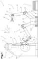
- a bending system 1 is shown with a manipulation system 2 shown in simplified form.
- the bending system 1 is designed in particular for the free bending of workpieces 3 to be manufactured from sheet metal by means of die bending, which can also be referred to as a production system.
- a metallic material is usually used as the starting material, which in its non-deformed state can be referred to as a flat material or flat element.
- Some system components of the bending system 1 are not shown or are only shown in a stylized way for the sake of clarity.
- the bending system 1 used for bending in the present case comprises at least one bending machine 4, in the present exemplary embodiment a bending press, in particular a press brake or press brake, for the production of the workpieces 3 or workpieces between at least one bending tool 5 that can be adjusted relative to one another.
- a bending press in particular a press brake or press brake
- only one bending machine was used 4, several of which can also be provided.
- the bending machine 4 is designed, among other things, for clamping the workpieces 3 or workpieces to be produced from the sheet metal between a clamping tool that can be adjusted relative to one another.
- the clamping tool then comprises at least a lower jaw and a cooperating upper jaw.
- the lower clamping jaw can also be referred to as the lower cheek or counter holder and the upper clamping jaw can also be referred to as the upper cheek or hold-down device.
- the lower clamping jaw can also be designed as a single punch.
- the bending machine 4 of the bending system 1 also includes a bending unit, which can also be referred to as a bending unit or forming unit. This training option for the bending machine 4 has only been described, but it is not shown in detail. The type and design of the bending machine 4 is not of essential importance in the process sequence described below. The main focus is more on the design of the manipulation system 2.
- the bending tool 5 of the bending machine 4 shown here and designed as a bending press comprises at least one bending punch 6, but usually several bending punches 6, and at least one bending die 7, but usually several bending dies 7 interacting with it.
- the at least one bending punch 6 is above the Arranged to be manufactured workpiece 3 on the bending machine 4 and held there accordingly, in particular clamped.
- the at least one bending die 7 is also held on the bending machine 4, in particular held clamped to it.
- the coordinate system is basically referred to as the “X” direction, which runs in a horizontal plane and in normal alignment with respect to the longitudinal extent of the bending tool 5, in particular its bending punch 6 and bending die 7. This is therefore the direction which also corresponds to the supply direction or the removal direction.
- the "Y” direction is understood to mean the vertical direction, which thus runs in the vertical direction of the bending tool 5 and further in the normal direction with respect to the horizontal plane.
- the “Z” direction is understood to mean that direction which runs in the longitudinal direction or in the longitudinal extension of the bending tool 5, in particular its bending punch 6 and bending die 7. The longitudinal extent of the bending edge or bending line defined by the bending tool 5 is thus also aligned in the “Z” direction.
- the bending machine 4 comprises a machine frame 8 which, for example, has a base plate 9 and side walls 10, 11 which project vertically therefrom and are spaced apart from one another in the transverse direction and aligned parallel to one another. These are preferred by one solid, for example formed from a sheet metal part cross brace 12 at their distanced from the bottom plate 9 end areas connected to each other.
- the side walls 10, 11 can be designed in an approximately C-shape to form a free space for the forming of the workpiece 3.
- the bending tool 5 is arranged and also held on press beams 13, 14.
- the lower press beam 13 is stationary and can also be referred to as a press table.
- the upper press beam 14 here is guided in linear guides 15 and can be adjusted relative to the lower press beam 13 in order to carry out the bending process.
- a drive arrangement 16 is provided for this purpose.
- a more detailed description and representation of a bending machine control unit, an input terminal and the energy supply have been omitted. Further details required for the operation of such a bending machine 4, such as feed devices or the like, are also omitted in the description of the subject in order to avoid an unnecessary length of the description.
- the manipulation system 2 comprises a first manipulator 17, at least one second manipulator 18 and a guide arrangement 19, on or on which the manipulators 17, 18 are adjustably guided along them.
- the adjustment movement can take place autonomously, it also being possible for drive energy and/or travel and/or adjustment commands to be transmitted from the guide arrangement 19 to the manipulators 17, 18.
- the guide arrangement 19 can, for example, comprise guide rails, guide rods or the like, which are preferably aligned to run in a straight line.
- the guide arrangement 19 defines a first axis 20 in the direction of its longitudinal extension.
- the guide arrangement 19 and thus also the first axis 20 preferably has a bending line or bending edge defined in a parallel direction with respect to a bending tool 5 or the clamping tool and is therefore also parallel with respect to the " aligned along the Z" axis of the coordinate system.
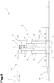
- manipulators 17, 18 The most important structural components of the manipulators 17, 18 are described below, the structural components of which are basically of the same design, but the arrangement on the manipulators 17, 18 can differ from one another. Those components of the first manipulator 17 are identified without inverted commas or without "'" and those of the second manipulator 18 are identified with inverted commas or with "'".
- Each of the manipulators 17, 18 comprises a base frame 21, 21' which is adjustably guided on the guide arrangement 19, e.g. by means of wheels and/or separate guide elements.
- the more detailed representation and description of drive means has been omitted, since this is well known and can be freely selected according to the known prior art.
- a first manipulator arm 22, 22' is mounted on the base frame 21, 21' so as to be pivotable about a second axis 23, 23'.
- a second manipulator arm 24, 24' is pivotably mounted about a third axis 25, 25' on each end region of the first manipulator arm 22, 22' that faces away from the base frame 21, 21'.
- a third manipulator arm 26, 26' is also provided, each of the third manipulator arms 26, 26' being pivotable about a fourth axis 27, 27' on a side facing away from the base frame 21, 21' on the respective second manipulator arm 24, 24' .
- the second axes 23, 23′, the third axes 25, 25′ and also the fourth axes 27, 27′ each and exclusively have a parallel alignment with respect to the first axis 20 .
- the axes mentioned above are also aligned parallel with respect to the bending line of the bending machine 4.
- the first manipulator arms 22, 22' can be arranged on the respective base frame 21, 21' either centrally on it or also on the side thereof, as is shown in the present exemplary embodiment.
- a holding arrangement 28, 28' is also arranged or provided on each of the third manipulator arms 26, 26'.
- the holding arrangement 28, 28' can, for example, be in the form of gripping tongs, a vacuum suction device, a holding magnet or the like.
- Each of the holding arrangements 28, 28' is mounted on the respective third manipulator arm 26, 26' such that it can be rotated about a fifth axis 29, 29'.
- Each of the fifth axes 29, 29' has a normal orientation with respect to the respective fourth axis 27, 27' and is thus oriented at right angles thereto. This possibility of rotation or pivoting allows the metal sheet or workpiece 3 held on the holding arrangement 28, 28' to be rotated, for example, about its own axis.
- each of the manipulators 17, 18 that each of the third manipulator arms 26, 26' is arranged on the side facing away from the first manipulator arm 22, 22' on the second manipulator arm 24, 24'.
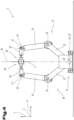
- the manipulators 17, 18 are arranged one behind the other on or on the common guide arrangement 19 and can be displaced along this relative thereto. Furthermore, the individual manipulator arms are arranged as mirror images of one another, with this taking place with respect to a fictitious normal plane between the two manipulators 17 , 18 to the first axis 20 .
- the third manipulator arm 26 of the first manipulator 17 is thus arranged on that side of the second manipulator arm 24 which faces the second manipulator 18 .
- the same also applies to the third manipulator arm 26' of the second manipulator 18.
- the third manipulator arm 26' of the second manipulator 18 is thus arranged on that side of the second manipulator arm 24' which faces the first manipulator 17.
- the second manipulator arm 24 of the first manipulator 17 is arranged on that side of its first manipulator arm 22 which faces the second manipulator 18 .
- the second manipulator arm 24' of the second manipulator 18 is also arranged on that side of its first manipulator arm 22' which faces the first manipulator 17. This means that each of the third manipulator arms 26, 26' is not on the same side as the first manipulator arms 22, 22'. There is always an arrangement in the direction of the opposite manipulator 18 or 17.
- the fifth axis 29 of the first manipulator 17 is arranged to run in a first normal plane 30 with respect to the first axis 20 . Provision is also made for the first normal plane 30 to be arranged at a distance from the base frame 21 of the first manipulator 17 in the direction of the first axis 20 and in the direction of the second manipulator 18 by a first distance 31 .
- the fifth axis 29 of the second manipulator 18 is arranged to run in a second normal plane 32 with respect to the first axis 20 . Furthermore, the second normal plane 32 is spaced apart by a second distance 33 from the base frame 21 ′ of the second manipulator 18 in the direction of the first axis 20 and in the direction of the first manipulator 17 .
- the manipulators 17, 18 In order to enable the two holding arrangements 28, 28' to be arranged opposite one another for the transfer process, at least one of the manipulators 17, 18 must be shifted in the direction of the other of the manipulators 18, 17. Due to the manipulators 17, 18 on the outside with respect to the base frame 21, 21' and located opposite The position of the third manipulator arms 26, 26 ⁇ , the manipulators 17, 18 can be arranged directly adjacent to one another.
- a sum of the first distance 31 plus the second distance 33 corresponds to at least one largest dimension of one of the third manipulator arms 26, 26 ⁇ in the direction of the first axis 20.
- the position of the manipulators 17, 18 and the manipulator arms before and during the transfer process is best from the Figures 2 to 4 to see. If, for example, a workpiece 3 or sheet metal is gripped by the holding arrangement 28 of the first manipulator 17 and this is to be transferred directly and without intermediate storage to the holding arrangement 28 ⁇ of the second manipulator 18, the third manipulator arms 26, 26 ⁇ must be aligned opposite one another and protruding towards one another .
- the holding arrangement 28 ⁇ of the second manipulator 18 can then likewise grasp the same workpiece 3 or sheet metal.
- the holding arrangement 28 of the first manipulator 17 is usually grasped or held on a first side and the holding arrangement 28 ⁇ of the second manipulator 18 is grasped or held on the opposite second side.
- the workpiece 3 or sheet metal can be released from the holding arrangement 28 of the first manipulator 17.
- a transfer from the holding arrangement 28' of the second manipulator 18 to the holding arrangement 28 of the first manipulator 17 takes place in the same way.
- the fifth axes 29, 29' of the third manipulator arms 26, 26' can preferably be arranged in a parallel alignment to one another for the transfer process. It can also be advantageous if the fifth axes 29, 29' of the third manipulator arms 26, 26' are arranged in alignment with one another for the transfer process.
- the first manipulator arm 22 and the second manipulator arm 24 of the first manipulator 17 are arranged on a first side with respect to a vertical center plane 34 of the guide arrangement 19 running in the direction of the first axis 20 .
- the first manipulator arm 22' and the second manipulator arm 24' of the second manipulator 18, on the other hand, can be or will be arranged on a second side, opposite the first side, of the center plane 34 of the guide arrangement 19.
- All information on value ranges in the present description is to be understood in such a way that it also includes any and all sub-ranges, e.g. the information 1 to 10 is to be understood in such a way that all sub-ranges, starting from the lower limit 1 and the upper limit 10, are also included , i.e. all subranges start with a lower limit of 1 or greater and end with an upper limit of 10 or less, e.g. 1 to 1.7, or 3.2 to 8.1, or 5.5 to 10.
- first distance 2 manipulation system 32 second normal level 3 workpiece 33 second distance 4 bending machine 34 midplane 5 bending tool 6 bending stamp 7 bending die 8th machine frame 9 bottom plate 10 sidewall 11 sidewall 12 cross-dressing 13 press bar 14 press bar 15 linear guide 16 drive assembly 17 first manipulator 18 second manipulator 19 guide arrangement 20 first axis 21 base frame 22 first manipulator arm 23 second axis 24 second manipulator arm 25 third axis 26 third manipulator arm 27 fourth axis 28 holding arrangement 29 fifth axis 30 first normal level
Landscapes
- Engineering & Computer Science (AREA)
- Mechanical Engineering (AREA)
- Robotics (AREA)
- Manipulator (AREA)
- Bending Of Plates, Rods, And Pipes (AREA)
Claims (13)
- Procédé pour le transfert direct d'au moins une tôle à plier ou d'une pièce (3) façonnée à partir de la tôle, dans une installation de pliage (1), avec au moins une machine de pliage (4), au moyen d'un système de manipulation (2), d'un premier manipulateur (17) vers au moins un deuxième manipulateur (18), dans lequel les étapes suivantes sont exécutées :- mise à disposition d'un dispositif de guidage commun (19), ce dispositif de guidage commun (19) définissant, en direction de son extension longitudinale, un premier axe commun (20) pour chacun des manipulateurs (17, 18) et chaque manipulateur (17, 18) étant mobile de manière autonome le long du dispositif de guidage commun (19) en direction du premier axe (20),- mise à disposition du premier manipulateur (17) et d'au moins le deuxième manipulateur (18), chacun des manipulateurs (17, 18) comprenant- un châssis de base (21, 21'),- un premier bras de manipulateur (22, 22'), dans lequel chacun des premiers bras de manipulateur (22, 22') peut pivoter, au niveau du châssis (21, 21') correspondant, autour d'un deuxième axe (23, 23'),- un deuxième bras de manipulateur (24, 24'), dans lequel chacun des deuxièmes bras de manipulateur (24, 24') peut pivoter, au niveau d'un côté opposé au châssis de base (21), sur le premier bras de manipulateur (22, 22') correspondant, autour d'un troisième axe (25, 25'),- un troisième bras de manipulateur (26, 26'), dans lequel chacun des troisièmes bras de manipulateur (26, 26') peut pivoter, au niveau d'un côté opposé au châssis de base (21, 21'), sur le deuxième bras de manipulateur (24, 24'), autour d'un quatrième axe (27, 27'),- dans lequel les deuxièmes axes (23, 23'), les troisièmes axes (25, 25') ainsi que les quatrièmes axes (27, 27') présentent chacun exclusivement une orientation parallèle par rapport au premier axe (20),- un dispositif de maintien (28, 28'), ce dispositif de maintien (28, 28') est disposé ou réalisé au niveau du troisième bras de manipulateur (26, 26') correspondant et chacun des dispositifs de maintien (28, 28') peut tourner autour d'un cinquième axe (29, 29'), dans lequel chacun des cinquièmes axes (29, 29') présente une orientation normale par rapport au quatrième axe (27, 27') correspondant,- dans lequel chacun des troisièmes bras de manipulateur (26, 26') est disposé sur le côté opposé au premier bras de manipulateur (22, 22') sur le deuxième manipulateur (24, 24'),- dans lequel une tôle ou une pièce (3) est saisie ou prise au niveau de son premier côté avec le dispositif de maintien (28) du premier manipulateur (17) et- dans lequel les manipulateurs (17, 18) sont disposés l'un derrière l'autre en direction du premier axe (20) au niveau ou sur le dispositif de guidage commun (19), et dans une position relative l'un par rapport à l'autre, dans laquelle le troisième bras de manipulateur (26) du premier manipulateur (17) est disposé du côté du deuxième bras de manipulateur (24) qui est orienté vers le deuxième manipulateur (18) et le troisième bras de manipulateur (26') du deuxième manipulateur (18) est disposé sur le côté du deuxième bras de manipulateur (24') qui est orienté vers le premier manipulateur (17),caractérisé en ce que- les manipulateurs (17, 18) pour le processus de transfert sont disposés de manière immédiatement adjacente entre eux et au moins un des manipulateurs (17, 18) est déplacé en direction de l'autre manipulateur (18, 17) et, en outre, les troisièmes bras de manipulateur (26, 26') sont orientés en face l'un de l'autre et leurs cinquièmes axes (29, 29') sont orientés de façon à dépasser respectivement l'un vers l'autre.- pour le processus de transfert, les premier et deuxième bras de manipulateur (22 ; 24) du premier manipulateur (17) sont disposés sur un premier côté par rapport à un plan central vertical (34) du dispositif de guidage (19), orienté de façon à s'étendre en direction du premier axe (20) et les premier et deuxième bras de manipulateur (22' ; 24') du deuxième manipulateur (18) sont disposés sur un deuxième côté, opposé au premier côté, du plan central (34) du dispositif de guidage (19), dans lequel le plan central vertical (34) s'étend dans une direction normale par rapport à un plan horizontal et- la même tôle ou pièce (3) est saisie ou prise, au niveau de son deuxième côté opposé au premier côté, avec le dispositif de maintien (28') du deuxième manipulateur (18) et la tôle ou la pièce (3) est libérée ou relâchée par le dispositif de maintien (28) du premier manipulateur (17).
- Procédé selon la revendication 1, caractérisé en ce que le deuxième bras de manipulateur (24) du premier manipulateur (17) est disposé sur le côté du premier bras de manipulateur (22) qui est orienté vers le deuxième manipulateur (18).
- Procédé selon la revendication 1 ou 2, caractérisé en ce que le deuxième bras de manipulateur (24') du deuxième manipulateur (18) est disposé sur le côté du premier bras de manipulateur (22') qui est orienté vers le premier manipulateur (17).
- Procédé selon l'une des revendications précédentes, caractérisé en ce que, pour le processus de transfert, les cinquièmes axes (29, 29') des troisièmes bras de manipulateur (26, 26') sont disposés respectivement avec une orientation parallèle entre eux.
- Procédé selon l'une des revendications précédentes, caractérisé en ce que, pour le processus de transfert, les cinquièmes axes (29, 29') des troisièmes bras de manipulateur (26, 26') sont disposés respectivement avec une orientation alignée entre eux.
- Procédé selon l'une des revendications précédentes, caractérisé en ce que, pour le premier axe (20) du dispositif de guidage (19) est disposée dans une orientation parallèle par rapport à une ligne de pliage définie par une machine de pliage (4) de l'installation de pliage (1).
- Système de manipulation (2) pour une installation de pliage (1) comprenant au moins une machine de pliage (4), pour le transfert direct d'au moins une tôle à plier ou d'une pièce (3) façonnée à partir de la tôle d'un premier manipulateur (17) vers au moins un deuxième manipulateur (18), ce système de manipulation (2) comprenant :- un dispositif de guidage commun (19), ce dispositif de guidage commun (19) définissant, en direction de son extension longitudinale, un premier axe commun (20) pour chacun des manipulateurs (17, 18) et chaque manipulateur (17, 18) du système de manipulation (2) est mobile de manière autonome le long du dispositif de guidage commun (19) en direction du premier axe (20),- le premier manipulateur (17) et l'au moins un deuxième manipulateur (18) comprennent chacun- un châssis de base (21, 21'),- un premier bras de manipulateur (22, 22'), dans lequel chacun des premiers bras de manipulateurs (22, 22') peut pivoter, au niveau du châssis de base (21, 21') correspondant, autour d'un deuxième axe (23, 23'),- un deuxième bras de manipulateur (24, 24'), dans lequel chacun des deuxièmes bras de manipulateur (24, 24') peut pivoter, au niveau d'un côté opposé au châssis de base (21, 21'), sur le premier bras de manipulateur (22, 22') correspondant, autour d'un troisième axe (25),- un troisième bras de manipulateur (26, 26'), dans lequel chacun des troisièmes bras de manipulateur (26, 26') peut pivoter, au niveau d'un côté opposé au châssis de base (21, 21'), sur le deuxième bras de manipulateur (24, 24'), autour d'un quatrième axe (27, 27'),- dans lequel les deuxièmes axes (23, 23'), les troisièmes axes (25, 25') ainsi que les quatrièmes axes (27, 27') de chaque manipulateur (17, 18) présentent chacun exclusivement une orientation parallèle par rapport au premier axe (20),- un dispositif de maintien (28, 28'), ce dispositif de maintien (28, 28') est disposé ou réalisé au niveau du troisième bras de manipulateur (26, 26') correspondant et chacun des dispositifs de maintien (28, 28') peut tourner autour d'un cinquième axe (29, 29'), dans lequel chacun des cinquièmes axes (29, 29') présente une orientation normale par rapport au quatrième axe (27, 27') correspondant, dans lequel- chacun des troisièmes bras de manipulateur (26, 26') est disposé sur le côté opposé au premier bras de manipulateur (22, 22') sur le deuxième manipulateur (24, 24'),- le premier manipulateur (17) et l'au moins un deuxième manipulateur (18) sont disposés l'un derrière l'autre en direction du premier axe (20) au niveau ou sur le dispositif de guidage commun (19), et dans une position relative l'un par rapport à l'autre, dans lequel le troisième bras de manipulateur (26) du premier manipulateur (17) est disposé du côté du deuxième bras de manipulateur (24) qui est orienté vers le deuxième manipulateur (18)- dans lequel le troisième bras de manipulateur (26') du deuxième manipulateur (18) est disposé sur le côté du deuxième bras de manipulateur (24') qui est orienté vers le premier manipulateur (17), plus particulièrement pour l'exécution du procédé de transfert direct selon l'une ds revendications précédentes,caractérisé en ce que- les manipulateurs (17, 18) pour le processus de transfert sont disposés de manière immédiatement adjacente entre eux et les troisièmes bras de manipulateur (26, 26') sont orientés en face l'un de l'autre et leurs cinquièmes axes (29, 29') sont orientés de façon à dépasser respectivement l'un vers l'autre et- pour le processus de transfert, les premier et deuxième bras de manipulateur (22 ; 24) du premier manipulateur (17) sont disposés sur un premier côté par rapport à un plan central vertical (34) du dispositif de guidage (19), orienté de façon à s'étendre en direction du premier axe (20) et les premier et deuxième bras de manipulateur (22' ; 24') du deuxième manipulateur (18) sont disposés sur un deuxième côté, opposé au premier côté, du plan central (34) du dispositif de guidage (19), dans lequel le plan central vertical (34) s'étend dans une direction normale par rapport à un plan horizontal.
- Système de manipulation (2) selon la revendication 7, caractérisé en ce que le deuxième bras de manipulateur (24) du premier manipulateur (17) est disposé sur le côté du premier bras de manipulateur (22) qui est orienté vers le deuxième manipulateur (18).
- Système de manipulation (2) selon la revendication 7 ou 8, caractérisé en ce que le deuxième bras de manipulateur (24') du deuxième manipulateur (18) est disposé sur le côté du premier bras de manipulateur (22') qui est orienté vers le premier manipulateur (17).
- Système de manipulation (2) selon l'une des revendications 7 à 9, caractérisé en ce que le cinquième axe (29) du premier manipulateur (17) est disposé de façon à s'étendre dans un premier plan normal (30) par rapport au premier axe (20) et le premier plan normal (30) est disposé à une première distance (31) du châssis de base (21) du premier manipulateur (17) en direction du premier axe (20) ainsi qu'en direction du deuxième manipulateur (18).
- Système de manipulation (2) selon l'une des revendications 7 à 10, caractérisé en ce que le cinquième axe (29') du deuxième manipulateur (18) est disposé de façon à s'étendre dans un deuxième plan normal (32) par rapport au premier axe (20) et le deuxième plan normal (32) est disposé à une deuxième distance (33) du châssis de base (21') du deuxième manipulateur (18) en direction du premier axe (20) ainsi qu'en direction du premier manipulateur (17).
- Système de manipulation (2) selon la revendication 10 ou 11, caractérisé en ce qu'une somme de la première distance (31) et de la deuxième distance (33) correspond au moins à la dimension la plus grande d'un des troisièmes bras de manipulateur (26, 26') en direction du premier axe (20).
- Installation de pliage (1) comprenant au moins une machine de pliage (4) et un système de manipulation (2) pour le transfert direct d'au moins une tôle à plier ou d'une pièce (3) façonnée à partir de la tôle, d'un premier manipulateur (17) vers au moins un deuxième manipulateur (18), caractérisé en ce que le système de manipulation (2) est conçu selon l'une des revendications 7 à 12.
Applications Claiming Priority (2)
| Application Number | Priority Date | Filing Date | Title |
|---|---|---|---|
| ATA50694/2019A AT522859B1 (de) | 2019-08-01 | 2019-08-01 | Übergabeverfahren, dafür ausgebildetes Manipulationssystem sowie Biegeanlage |
| PCT/AT2020/060283 WO2021016646A1 (fr) | 2019-08-01 | 2020-07-30 | Procédé de transfert, système de manipulation conçu pour celui-ci, et unité de pliage |
Publications (3)
| Publication Number | Publication Date |
|---|---|
| EP4007664A1 EP4007664A1 (fr) | 2022-06-08 |
| EP4007664C0 EP4007664C0 (fr) | 2023-09-06 |
| EP4007664B1 true EP4007664B1 (fr) | 2023-09-06 |
Family
ID=72421997
Family Applications (1)
| Application Number | Title | Priority Date | Filing Date |
|---|---|---|---|
| EP20767947.3A Active EP4007664B1 (fr) | 2019-08-01 | 2020-07-30 | Procédé de transfert, système de manipulation conçu pour celui-ci, et unité de pliage |
Country Status (6)
| Country | Link |
|---|---|
| US (1) | US20220314298A1 (fr) |
| EP (1) | EP4007664B1 (fr) |
| JP (1) | JP7358616B2 (fr) |
| CN (1) | CN114206522A (fr) |
| AT (1) | AT522859B1 (fr) |
| WO (1) | WO2021016646A1 (fr) |
Families Citing this family (2)
| Publication number | Priority date | Publication date | Assignee | Title |
|---|---|---|---|---|
| CN113020359B (zh) * | 2021-03-01 | 2022-01-25 | 广东百能家居有限公司 | 一种用于不锈钢橱柜生产的水槽制作方法及设备 |
| CN115047203A (zh) * | 2022-07-27 | 2022-09-13 | 上海富科思分析仪器有限公司 | 自动溶出系统 |
Family Cites Families (16)
| Publication number | Priority date | Publication date | Assignee | Title |
|---|---|---|---|---|
| DE8817048U1 (de) * | 1988-05-19 | 1992-03-12 | Kuka Schweissanlagen + Roboter Gmbh, 8900 Augsburg | Vorrichtung zum Handhaben, insbesondere Transportieren von Werkstücken zwischen zwei benachbarten Bearbeitungsstationen |
| IT1295906B1 (it) * | 1997-10-31 | 1999-05-28 | Antil Srl | Procedimento e apparecchiatura per la piegatura in automatico di lamiere in fogli |
| DE102004035797B9 (de) * | 2004-07-23 | 2006-07-13 | Langenstein & Schemann Gmbh | Verfahren und Vorrichtung zum Überführen eines Werkstücks |
| NL1028129C2 (nl) * | 2005-01-26 | 2006-07-27 | Safan Bv | Werkwijze voor het buigen van plaatvormig materiaal en pers voor het buigen van plaatvormig materiaal. |
| NL1032400C2 (nl) * | 2006-08-31 | 2008-03-03 | Safan Bv | Plaatmanipulatie. |
| DE102008009995A1 (de) * | 2008-02-19 | 2009-08-20 | Kuka Systems Gmbh | Verfahren und Vorrichtung zum Transportieren von Werkstücken |
| SI2195267T2 (sl) * | 2008-03-12 | 2019-02-28 | Schuler Automation Gmbh & Co. Kg | Postopek za razkladanje ploščastih delov |
| JP6039187B2 (ja) * | 2012-02-03 | 2016-12-07 | キヤノン株式会社 | 組立装置、把持ハンドおよび物品の組立方法 |
| US20150217359A1 (en) * | 2012-06-15 | 2015-08-06 | Abb Technology Ag | Stacking Line System And Method For Stacking Blanks Outputted From A Blanking Shear Or Press |
| KR101212195B1 (ko) * | 2012-07-19 | 2012-12-13 | 미원정밀공업(주) | 탠덤 프레스 라인용 더블 로봇라인을 이용한 프레스 성형품 자동 제조시스템 |
| JP5678979B2 (ja) * | 2013-03-15 | 2015-03-04 | 株式会社安川電機 | ロボットシステム、校正方法及び被加工物の製造方法 |
| WO2015075778A1 (fr) * | 2013-11-19 | 2015-05-28 | 株式会社安川電機 | Système robotisé |
| JP6619560B2 (ja) * | 2015-04-15 | 2019-12-11 | 株式会社オプトン | 曲げ加工装置 |
| CN105215160B (zh) | 2015-10-29 | 2018-11-06 | 武汉理工大学 | 一种多工位连续热冲压生产线及方法 |
| CN205341712U (zh) * | 2016-01-26 | 2016-06-29 | 武汉智孚机器人工程有限公司 | 一种钢板自动化折弯系统 |
| US11278951B2 (en) * | 2016-12-27 | 2022-03-22 | Abb Schweiz Ag | Pendular handling system for a press line |
-
2019
- 2019-08-01 AT ATA50694/2019A patent/AT522859B1/de not_active IP Right Cessation
-
2020
- 2020-07-30 US US17/627,206 patent/US20220314298A1/en not_active Abandoned
- 2020-07-30 JP JP2022506654A patent/JP7358616B2/ja active Active
- 2020-07-30 EP EP20767947.3A patent/EP4007664B1/fr active Active
- 2020-07-30 CN CN202080055887.8A patent/CN114206522A/zh active Pending
- 2020-07-30 WO PCT/AT2020/060283 patent/WO2021016646A1/fr not_active Ceased
Also Published As
| Publication number | Publication date |
|---|---|
| AT522859A1 (de) | 2021-02-15 |
| US20220314298A1 (en) | 2022-10-06 |
| EP4007664C0 (fr) | 2023-09-06 |
| EP4007664A1 (fr) | 2022-06-08 |
| JP7358616B2 (ja) | 2023-10-10 |
| CN114206522A (zh) | 2022-03-18 |
| AT522859B1 (de) | 2021-12-15 |
| WO2021016646A1 (fr) | 2021-02-04 |
| JP2022543096A (ja) | 2022-10-07 |
Similar Documents
| Publication | Publication Date | Title |
|---|---|---|
| EP3528976B1 (fr) | Installation de fabrication présentant un dispositif de manipulation | |
| EP2152446B1 (fr) | Dispositif de centrage pour des pièces à usiner planes dans une presse | |
| DE19621658C2 (de) | Bearbeitungsmaschine für plattenförmige Werkstücke, insbesondere zur Erzeugung von gebogenen Rändern an Blechteilen | |
| EP2707317B1 (fr) | Dispositif permettant de déplacer des roues de véhicule | |
| EP3448597B1 (fr) | Procédé de transport pour la manutention de pièces | |
| EP2707160A1 (fr) | Installation de fabrication comportant un système de changement d'outil | |
| DE102017121557B4 (de) | Verfahren und Vorrichtung zur Förderung und Positionierung von Werkstücken | |
| DE112016002792T5 (de) | Reckwalzmaschine und Reckwalzverfahren | |
| EP4007664B1 (fr) | Procédé de transfert, système de manipulation conçu pour celui-ci, et unité de pliage | |
| EP0136598A2 (fr) | Dispositif pour la manipulation de feuilles de tôle | |
| EP3138778B1 (fr) | Machine de verrouillage de coques | |
| DE19615251C2 (de) | Verfahren und Vorrichtung zum Bearbeiten von Werkstücken in einer Gesenkbiegepresse | |
| EP3448596A1 (fr) | Dispositif de transport à pinces de préhension | |
| EP3448595B1 (fr) | Dispositif de transport pour déplacer des pièces dans un dispositif d'usinage | |
| DE102019107077B4 (de) | Förderanlage zum Umsetzen zumindest eines plattenförmigen Werkstücks | |
| EP2675599A1 (fr) | Module de manutention de roues de véhicules automobiles | |
| EP3302840B2 (fr) | Installation de fabrication pour la fabrication de pièces en tôle et procédé à cet effet | |
| AT504171B1 (de) | Verfahren zum be- und entladen einer werkzeugmaschine mit werkzeugen | |
| DE102020108037B4 (de) | Positionierungseinrichtung und Verfahren zur Positionierung von Werkstücken | |
| EP2494499B1 (fr) | Changeur de documents | |
| EP4419270B1 (fr) | Machine de cintrage à pivotement | |
| DE102017115411B4 (de) | Vorrichtung zum Stapeln oder Entstapeln von Bauteilen | |
| AT526774B1 (de) | Pult zur Ablage eines Werkstücks aus Blech | |
| EP2783770B1 (fr) | Dispositif et procédé de manipulation de pièces en tôle sur une machine-outil destinée au traitement de découpe de tôles | |
| EP3181254B1 (fr) | Installation de fabrication comprenant une unité de manipulation d'outil |
Legal Events
| Date | Code | Title | Description |
|---|---|---|---|
| STAA | Information on the status of an ep patent application or granted ep patent |
Free format text: STATUS: UNKNOWN |
|
| STAA | Information on the status of an ep patent application or granted ep patent |
Free format text: STATUS: THE INTERNATIONAL PUBLICATION HAS BEEN MADE |
|
| PUAI | Public reference made under article 153(3) epc to a published international application that has entered the european phase |
Free format text: ORIGINAL CODE: 0009012 |
|
| STAA | Information on the status of an ep patent application or granted ep patent |
Free format text: STATUS: REQUEST FOR EXAMINATION WAS MADE |
|
| 17P | Request for examination filed |
Effective date: 20220301 |
|
| AK | Designated contracting states |
Kind code of ref document: A1 Designated state(s): AL AT BE BG CH CY CZ DE DK EE ES FI FR GB GR HR HU IE IS IT LI LT LU LV MC MK MT NL NO PL PT RO RS SE SI SK SM TR |
|
| DAV | Request for validation of the european patent (deleted) | ||
| DAX | Request for extension of the european patent (deleted) | ||
| GRAP | Despatch of communication of intention to grant a patent |
Free format text: ORIGINAL CODE: EPIDOSNIGR1 |
|
| STAA | Information on the status of an ep patent application or granted ep patent |
Free format text: STATUS: GRANT OF PATENT IS INTENDED |
|
| INTG | Intention to grant announced |
Effective date: 20230310 |
|
| GRAS | Grant fee paid |
Free format text: ORIGINAL CODE: EPIDOSNIGR3 |
|
| GRAA | (expected) grant |
Free format text: ORIGINAL CODE: 0009210 |
|
| STAA | Information on the status of an ep patent application or granted ep patent |
Free format text: STATUS: THE PATENT HAS BEEN GRANTED |
|
| AK | Designated contracting states |
Kind code of ref document: B1 Designated state(s): AL AT BE BG CH CY CZ DE DK EE ES FI FR GB GR HR HU IE IS IT LI LT LU LV MC MK MT NL NO PL PT RO RS SE SI SK SM TR |
|
| REG | Reference to a national code |
Ref country code: GB Ref legal event code: FG4D Free format text: NOT ENGLISH |
|
| REG | Reference to a national code |
Ref country code: CH Ref legal event code: EP |
|
| REG | Reference to a national code |
Ref country code: IE Ref legal event code: FG4D Free format text: LANGUAGE OF EP DOCUMENT: GERMAN |
|
| REG | Reference to a national code |
Ref country code: DE Ref legal event code: R096 Ref document number: 502020005166 Country of ref document: DE |
|
| U01 | Request for unitary effect filed |
Effective date: 20231004 |
|
| U07 | Unitary effect registered |
Designated state(s): AT BE BG DE DK EE FI FR IT LT LU LV MT NL PT SE SI Effective date: 20231013 |
|
| PG25 | Lapsed in a contracting state [announced via postgrant information from national office to epo] |
Ref country code: GR Free format text: LAPSE BECAUSE OF FAILURE TO SUBMIT A TRANSLATION OF THE DESCRIPTION OR TO PAY THE FEE WITHIN THE PRESCRIBED TIME-LIMIT Effective date: 20231207 |
|
| PG25 | Lapsed in a contracting state [announced via postgrant information from national office to epo] |
Ref country code: RS Free format text: LAPSE BECAUSE OF FAILURE TO SUBMIT A TRANSLATION OF THE DESCRIPTION OR TO PAY THE FEE WITHIN THE PRESCRIBED TIME-LIMIT Effective date: 20230906 Ref country code: NO Free format text: LAPSE BECAUSE OF FAILURE TO SUBMIT A TRANSLATION OF THE DESCRIPTION OR TO PAY THE FEE WITHIN THE PRESCRIBED TIME-LIMIT Effective date: 20231206 Ref country code: HR Free format text: LAPSE BECAUSE OF FAILURE TO SUBMIT A TRANSLATION OF THE DESCRIPTION OR TO PAY THE FEE WITHIN THE PRESCRIBED TIME-LIMIT Effective date: 20230906 Ref country code: GR Free format text: LAPSE BECAUSE OF FAILURE TO SUBMIT A TRANSLATION OF THE DESCRIPTION OR TO PAY THE FEE WITHIN THE PRESCRIBED TIME-LIMIT Effective date: 20231207 |
|
| PG25 | Lapsed in a contracting state [announced via postgrant information from national office to epo] |
Ref country code: IS Free format text: LAPSE BECAUSE OF FAILURE TO SUBMIT A TRANSLATION OF THE DESCRIPTION OR TO PAY THE FEE WITHIN THE PRESCRIBED TIME-LIMIT Effective date: 20240106 |
|
| PG25 | Lapsed in a contracting state [announced via postgrant information from national office to epo] |
Ref country code: ES Free format text: LAPSE BECAUSE OF FAILURE TO SUBMIT A TRANSLATION OF THE DESCRIPTION OR TO PAY THE FEE WITHIN THE PRESCRIBED TIME-LIMIT Effective date: 20230906 |
|
| PG25 | Lapsed in a contracting state [announced via postgrant information from national office to epo] |
Ref country code: SM Free format text: LAPSE BECAUSE OF FAILURE TO SUBMIT A TRANSLATION OF THE DESCRIPTION OR TO PAY THE FEE WITHIN THE PRESCRIBED TIME-LIMIT Effective date: 20230906 Ref country code: RO Free format text: LAPSE BECAUSE OF FAILURE TO SUBMIT A TRANSLATION OF THE DESCRIPTION OR TO PAY THE FEE WITHIN THE PRESCRIBED TIME-LIMIT Effective date: 20230906 Ref country code: IS Free format text: LAPSE BECAUSE OF FAILURE TO SUBMIT A TRANSLATION OF THE DESCRIPTION OR TO PAY THE FEE WITHIN THE PRESCRIBED TIME-LIMIT Effective date: 20240106 Ref country code: ES Free format text: LAPSE BECAUSE OF FAILURE TO SUBMIT A TRANSLATION OF THE DESCRIPTION OR TO PAY THE FEE WITHIN THE PRESCRIBED TIME-LIMIT Effective date: 20230906 Ref country code: CZ Free format text: LAPSE BECAUSE OF FAILURE TO SUBMIT A TRANSLATION OF THE DESCRIPTION OR TO PAY THE FEE WITHIN THE PRESCRIBED TIME-LIMIT Effective date: 20230906 Ref country code: SK Free format text: LAPSE BECAUSE OF FAILURE TO SUBMIT A TRANSLATION OF THE DESCRIPTION OR TO PAY THE FEE WITHIN THE PRESCRIBED TIME-LIMIT Effective date: 20230906 |
|
| PG25 | Lapsed in a contracting state [announced via postgrant information from national office to epo] |
Ref country code: PL Free format text: LAPSE BECAUSE OF FAILURE TO SUBMIT A TRANSLATION OF THE DESCRIPTION OR TO PAY THE FEE WITHIN THE PRESCRIBED TIME-LIMIT Effective date: 20230906 |
|
| REG | Reference to a national code |
Ref country code: DE Ref legal event code: R097 Ref document number: 502020005166 Country of ref document: DE |
|
| PLBE | No opposition filed within time limit |
Free format text: ORIGINAL CODE: 0009261 |
|
| STAA | Information on the status of an ep patent application or granted ep patent |
Free format text: STATUS: NO OPPOSITION FILED WITHIN TIME LIMIT |
|
| 26N | No opposition filed |
Effective date: 20240607 |
|
| PG25 | Lapsed in a contracting state [announced via postgrant information from national office to epo] |
Ref country code: MC Free format text: LAPSE BECAUSE OF FAILURE TO SUBMIT A TRANSLATION OF THE DESCRIPTION OR TO PAY THE FEE WITHIN THE PRESCRIBED TIME-LIMIT Effective date: 20230906 |
|
| REG | Reference to a national code |
Ref country code: CH Ref legal event code: PL |
|
| U90 | Renewal fees not paid: noting of loss of rights |
Free format text: RENEWAL FEE NOT PAID FOR YEAR 05 Effective date: 20250214 |
|
| GBPC | Gb: european patent ceased through non-payment of renewal fee |
Effective date: 20240730 |
|
| PG25 | Lapsed in a contracting state [announced via postgrant information from national office to epo] |
Ref country code: CH Free format text: LAPSE BECAUSE OF NON-PAYMENT OF DUE FEES Effective date: 20240731 |
|
| PG25 | Lapsed in a contracting state [announced via postgrant information from national office to epo] |
Ref country code: GB Free format text: LAPSE BECAUSE OF NON-PAYMENT OF DUE FEES Effective date: 20240730 |
|
| U93 | Unitary patent lapsed |
Free format text: RENEWAL FEE NOT PAID Effective date: 20240731 |
|
| PG25 | Lapsed in a contracting state [announced via postgrant information from national office to epo] |
Ref country code: IE Free format text: LAPSE BECAUSE OF NON-PAYMENT OF DUE FEES Effective date: 20240730 |
|
| PG25 | Lapsed in a contracting state [announced via postgrant information from national office to epo] |
Ref country code: CY Free format text: LAPSE BECAUSE OF FAILURE TO SUBMIT A TRANSLATION OF THE DESCRIPTION OR TO PAY THE FEE WITHIN THE PRESCRIBED TIME-LIMIT; INVALID AB INITIO Effective date: 20200730 |
|
| PG25 | Lapsed in a contracting state [announced via postgrant information from national office to epo] |
Ref country code: HU Free format text: LAPSE BECAUSE OF FAILURE TO SUBMIT A TRANSLATION OF THE DESCRIPTION OR TO PAY THE FEE WITHIN THE PRESCRIBED TIME-LIMIT; INVALID AB INITIO Effective date: 20200730 |