EP3187807B1 - Dispositif de séchage de foin - Google Patents
Dispositif de séchage de foin Download PDFInfo
- Publication number
- EP3187807B1 EP3187807B1 EP17156316.6A EP17156316A EP3187807B1 EP 3187807 B1 EP3187807 B1 EP 3187807B1 EP 17156316 A EP17156316 A EP 17156316A EP 3187807 B1 EP3187807 B1 EP 3187807B1
- Authority
- EP
- European Patent Office
- Prior art keywords
- air
- ventilation box
- ventilation
- hay
- sucked
- Prior art date
- Legal status (The legal status is an assumption and is not a legal conclusion. Google has not performed a legal analysis and makes no representation as to the accuracy of the status listed.)
- Active
Links
Images
Classifications
-
- A—HUMAN NECESSITIES
- A01—AGRICULTURE; FORESTRY; ANIMAL HUSBANDRY; HUNTING; TRAPPING; FISHING
- A01F—PROCESSING OF HARVESTED PRODUCE; HAY OR STRAW PRESSES; DEVICES FOR STORING AGRICULTURAL OR HORTICULTURAL PRODUCE
- A01F25/00—Storing agricultural or horticultural produce; Hanging-up harvested fruit
- A01F25/04—Stacks, ricks or the like
- A01F25/08—Ventilating means
-
- A—HUMAN NECESSITIES
- A01—AGRICULTURE; FORESTRY; ANIMAL HUSBANDRY; HUNTING; TRAPPING; FISHING
- A01F—PROCESSING OF HARVESTED PRODUCE; HAY OR STRAW PRESSES; DEVICES FOR STORING AGRICULTURAL OR HORTICULTURAL PRODUCE
- A01F25/00—Storing agricultural or horticultural produce; Hanging-up harvested fruit
- A01F25/14—Containers specially adapted for storing
-
- A—HUMAN NECESSITIES
- A01—AGRICULTURE; FORESTRY; ANIMAL HUSBANDRY; HUNTING; TRAPPING; FISHING
- A01F—PROCESSING OF HARVESTED PRODUCE; HAY OR STRAW PRESSES; DEVICES FOR STORING AGRICULTURAL OR HORTICULTURAL PRODUCE
- A01F25/00—Storing agricultural or horticultural produce; Hanging-up harvested fruit
- A01F25/16—Arrangements in forage silos
- A01F25/22—Ventilating arrangements
-
- B—PERFORMING OPERATIONS; TRANSPORTING
- B65—CONVEYING; PACKING; STORING; HANDLING THIN OR FILAMENTARY MATERIAL
- B65D—CONTAINERS FOR STORAGE OR TRANSPORT OF ARTICLES OR MATERIALS, e.g. BAGS, BARRELS, BOTTLES, BOXES, CANS, CARTONS, CRATES, DRUMS, JARS, TANKS, HOPPERS, FORWARDING CONTAINERS; ACCESSORIES, CLOSURES, OR FITTINGS THEREFOR; PACKAGING ELEMENTS; PACKAGES
- B65D88/00—Large containers
- B65D88/74—Large containers having means for heating, cooling, aerating or other conditioning of contents
-
- F—MECHANICAL ENGINEERING; LIGHTING; HEATING; WEAPONS; BLASTING
- F26—DRYING
- F26B—DRYING SOLID MATERIALS OR OBJECTS BY REMOVING LIQUID THEREFROM
- F26B21/00—Arrangements for supplying or controlling air or other gases for drying solid materials or objects
- F26B21/20—Circulating air or gases in closed cycles, e.g. wholly within the drying enclosure
- F26B21/202—Circulating air or gases in closed cycles, e.g. wholly within the drying enclosure with means for changing the flow pattern, e.g. by reversing gas flow or by moving the materials or objects through subsequent compartments, at least two of which have a different flow direction
-
- F—MECHANICAL ENGINEERING; LIGHTING; HEATING; WEAPONS; BLASTING
- F26—DRYING
- F26B—DRYING SOLID MATERIALS OR OBJECTS BY REMOVING LIQUID THEREFROM
- F26B21/00—Arrangements for supplying or controlling air or other gases for drying solid materials or objects
- F26B21/20—Circulating air or gases in closed cycles, e.g. wholly within the drying enclosure
- F26B21/25—Circulating air or gases in closed cycles, e.g. wholly within the drying enclosure partly outside the drying enclosure
-
- F—MECHANICAL ENGINEERING; LIGHTING; HEATING; WEAPONS; BLASTING
- F26—DRYING
- F26B—DRYING SOLID MATERIALS OR OBJECTS BY REMOVING LIQUID THEREFROM
- F26B21/00—Arrangements for supplying or controlling air or other gases for drying solid materials or objects
- F26B21/30—Controlling, e.g. regulating, parameters of gas supply
- F26B21/33—Humidity
- F26B21/333—Humidity by condensing the moisture in the drying medium, which may be recycled, e.g. using a heat pump cycle
-
- F—MECHANICAL ENGINEERING; LIGHTING; HEATING; WEAPONS; BLASTING
- F26—DRYING
- F26B—DRYING SOLID MATERIALS OR OBJECTS BY REMOVING LIQUID THEREFROM
- F26B21/00—Arrangements for supplying or controlling air or other gases for drying solid materials or objects
- F26B21/30—Controlling, e.g. regulating, parameters of gas supply
- F26B21/35—Temperature; Pressure
-
- F—MECHANICAL ENGINEERING; LIGHTING; HEATING; WEAPONS; BLASTING
- F26—DRYING
- F26B—DRYING SOLID MATERIALS OR OBJECTS BY REMOVING LIQUID THEREFROM
- F26B21/00—Arrangements for supplying or controlling air or other gases for drying solid materials or objects
- F26B21/30—Controlling, e.g. regulating, parameters of gas supply
- F26B21/37—Velocity of flow; Quantity of flow
-
- F—MECHANICAL ENGINEERING; LIGHTING; HEATING; WEAPONS; BLASTING
- F26—DRYING
- F26B—DRYING SOLID MATERIALS OR OBJECTS BY REMOVING LIQUID THEREFROM
- F26B3/00—Drying solid materials or objects by processes involving the application of heat
- F26B3/02—Drying solid materials or objects by processes involving the application of heat by convection, i.e. heat being conveyed from a heat source to the materials or objects to be dried by a gas or vapour, e.g. air
- F26B3/06—Drying solid materials or objects by processes involving the application of heat by convection, i.e. heat being conveyed from a heat source to the materials or objects to be dried by a gas or vapour, e.g. air the gas or vapour flowing through the materials or objects to be dried
-
- F—MECHANICAL ENGINEERING; LIGHTING; HEATING; WEAPONS; BLASTING
- F26—DRYING
- F26B—DRYING SOLID MATERIALS OR OBJECTS BY REMOVING LIQUID THEREFROM
- F26B3/00—Drying solid materials or objects by processes involving the application of heat
- F26B3/28—Drying solid materials or objects by processes involving the application of heat by radiation, e.g. from the sun
- F26B3/283—Drying solid materials or objects by processes involving the application of heat by radiation, e.g. from the sun in combination with convection
- F26B3/286—Drying solid materials or objects by processes involving the application of heat by radiation, e.g. from the sun in combination with convection by solar radiation
-
- F—MECHANICAL ENGINEERING; LIGHTING; HEATING; WEAPONS; BLASTING
- F26—DRYING
- F26B—DRYING SOLID MATERIALS OR OBJECTS BY REMOVING LIQUID THEREFROM
- F26B9/00—Machines or apparatus for drying solid materials or objects at rest or with only local agitation; Domestic airing cupboards
- F26B9/06—Machines or apparatus for drying solid materials or objects at rest or with only local agitation; Domestic airing cupboards in stationary drums or chambers
- F26B9/063—Machines or apparatus for drying solid materials or objects at rest or with only local agitation; Domestic airing cupboards in stationary drums or chambers for drying granular material in bulk, e.g. grain bins or silos with false floor
-
- F—MECHANICAL ENGINEERING; LIGHTING; HEATING; WEAPONS; BLASTING
- F26—DRYING
- F26B—DRYING SOLID MATERIALS OR OBJECTS BY REMOVING LIQUID THEREFROM
- F26B2200/00—Drying processes and machines for solid materials characterised by the specific requirements of the drying goods
- F26B2200/06—Grains, e.g. cereals, wheat, rice, corn
-
- Y—GENERAL TAGGING OF NEW TECHNOLOGICAL DEVELOPMENTS; GENERAL TAGGING OF CROSS-SECTIONAL TECHNOLOGIES SPANNING OVER SEVERAL SECTIONS OF THE IPC; TECHNICAL SUBJECTS COVERED BY FORMER USPC CROSS-REFERENCE ART COLLECTIONS [XRACs] AND DIGESTS
- Y02—TECHNOLOGIES OR APPLICATIONS FOR MITIGATION OR ADAPTATION AGAINST CLIMATE CHANGE
- Y02B—CLIMATE CHANGE MITIGATION TECHNOLOGIES RELATED TO BUILDINGS, e.g. HOUSING, HOUSE APPLIANCES OR RELATED END-USER APPLICATIONS
- Y02B40/00—Technologies aiming at improving the efficiency of home appliances, e.g. induction cooking or efficient technologies for refrigerators, freezers or dish washers
- Y02B40/18—Technologies aiming at improving the efficiency of home appliances, e.g. induction cooking or efficient technologies for refrigerators, freezers or dish washers using renewables, e.g. solar cooking stoves, furnaces or solar heating
Definitions
- the present invention relates to a device for drying hay, comprising a ventilation box for receiving the hay, the ventilation box being covered with a roof, the device further comprising at least one fan, by means of which fan air can be sucked in, the sucked-in air at least partially Dehumidifier can be supplied in order to dehumidify the air, and whereby the air can finally be blown through the ventilation box, from an initial area to an end area of the ventilation box by means of the at least one fan, the hay being able to be arranged between a starting area and an end area on a box surface which can be flowed through by the air is provided, wherein a changeover flap is provided which can be moved from a first position to a second position, in the first position the air can only be sucked out of the ventilation box by the at least one fan in order to form a closed air circuit in the device , and wherein in the second position the air can be sucked in at least partially from outside the ventilation box, several, preferably five ventilation boxes being
- GB 2463747 A known that relates to a heating and ventilation system for storage for perishable goods. Air is blown in through a duct by means of a fan in order to set a desired air humidity and temperature.
- the fan is arranged in a housing which has a closable inlet in order to selectively draw in air from the outside or from the inside of the store.
- flaps are provided in the accumulator, from which air can escape to the outside in order not to let the pressure in the accumulator become too great.
- heaters are provided to dry air that has been sucked in from the outside.
- a device for drying and storing grain or rice which comprises several ventilation boxes, a fan, a dehumidifier, various ducts, exhaust fans, a switching flap, air guiding flaps, air guiding means and a regulating or control unit, with the switching flap being controlled by means of the regulation and control unit is not disclosed.
- the material to be dried is placed in a ventilation box between an initial area and an end area of the ventilation box.
- the ventilation box protects the items to be dried from the weather from outside the ventilation box and is accordingly equipped with a roof.
- the material to be dried is arranged on a flowable box surface, the flowable box surface does not necessarily have to be a horizontal surface, but can also be a vertical surface or an inclined surface with an inclination between the horizontal and the vertical.
- Air for drying is sucked in with at least one fan and at least partially supplied to a dehumidifier. The air is then blown through the ventilation box with the at least one fan, from the start area to the end area.
- the invention is based on the idea of using existing heat sources in a targeted and controlled manner in order to heat the air for drying.
- air from outside ie from outside the ventilation box
- is sucked in can be warmed with existing heat sources.
- Solar energy is preferably used for heating the air sucked in from the outside.
- this air is only supplied to the dehumidifier or an air circuit in the ventilation box if it is warm enough, otherwise the air temperature in the ventilation box would cool down.
- the device further comprises at least one fan, by means of which fan air can be sucked in, the sucked-in air at least partially Dehumidifier can be supplied in order to dehumidify the air, and wherein the air can finally be blown through the ventilation box, from an initial area to an end area of the ventilation box by means of the at least one fan, the items to be dried being arranged between a starting area and an end area on a box surface which can be flowed through by the air
- a switching flap is provided which is movable from a first position to a second position, wherein in the first position, the air can only be sucked out of the ventilation box by the at least one fan in order to keep a closed air Training circuit in the device, and wherein in the second position, the air is at least partially sucked in from outside the ventilation box.
- An outside temperature, ie the temperature of the air drawn in from outside the ventilation box, and / or an inside temperature, ie the temperature of the air in the ventilation box, and / or the difference between outside temperature and inside temperature is preferably used to control the switching flap. Accordingly, in a method for drying material to be dried, it is provided according to the invention that an apparatus according to the invention is used and that Material to be dried is fed into the ventilation box and that an outside temperature of the air that can be sucked in from outside the ventilation box is measured, an inside temperature of the air in the ventilation box being measured, preferably in the end area, and the switch cap depending on the outside temperature and / or the inside temperature and / or the difference between the outside temperature and the inside temperature is moved from the first position to the second position and vice versa.
- Embodiments in which only the outside temperature or only the inside temperature is used to control the switchover flap can prove to be particularly simple in construction.
- the switching flap is moved into the second position or is held in the second position if the outside temperature is greater than or equal to an outside temperature threshold value and / or if the difference between the outside temperature and the inside temperature is greater than or equal to a positive differential temperature threshold.
- the changeover flap it is of course also conceivable for the changeover flap to be moved into the second position or to be held in the second position if the inside temperature is less than or equal to a certain inside temperature threshold value.
- the outside temperature threshold value is between 22 ° C. and 27 ° C., preferably 25 ° C.
- the positive differential temperature threshold value is between 2 ° C. and 5 ° C. preferably at 3 ° C.
- the switchover flap also allows specific cool air to be sucked in from the outside, possibly dehumidified and blown into the ventilation box if the temperature in the ventilation box is to be lowered in a targeted manner. It is therefore provided in a preferred embodiment of the method according to the invention that the changeover flap is moved into the second position or is held in the second position if the difference between the outside temperature and the inside temperature is less than or equal to a negative differential temperature threshold value.
- the changeover flap is moved into the second position or held in the second position if the inside temperature is greater than a certain inside temperature threshold and / or the outside temperature is less than a certain outside temperature threshold.
- the negative differential temperature threshold is between -5 ° C and -2 ° C, preferably -3 ° C.
- an air duct is provided under the roof, along which air can be sucked in from the outside of the ventilation box in the second position along the roof to conduct and allow heat transfer between the roof and the air.
- the roof allows a large area to be made available that is illuminated by the sun in a structurally simple manner. Accordingly, the air sucked in from the outside can be warmed up very well even in moderate sunshine before it is fed to the dehumidifier.
- the roof is designed as a sheet metal roof, preferably made of trapezoidal sheets.
- a cylinder preferably an electric cylinder is provided to move the switching flap back and forth between the first position and the second position.
- a cylinder preferably an electric cylinder is provided to move the switching flap back and forth between the first position and the second position.
- differently operated cylinders are also conceivable, for example hydraulic or pneumatic cylinders.
- the dehumidifier only needs to be switched on when the relative humidity of the air drawn in from outside is more than 50%.
- a structurally simple solution consists in always leading all of the intake air through the dehumidifier and only switching on the dehumidifier when necessary. This is irrespective of the position of the switch flap, i.e. even if no air is drawn in from the outside, but only from the ventilation box. It is therefore provided in a preferred embodiment of the device according to the invention that all of the air drawn in can be fed to the dehumidifier.
- the dehumidifier has an evaporator in which refrigerant is evaporated by the heat of the intake air, which in turn cools the intake air below the dew point.
- refrigerant is evaporated by the heat of the intake air, which in turn cools the intake air below the dew point.
- water condenses on the cold surface of the evaporator and runs or drips from the evaporator.
- the dehumidifier has an evaporator and a condenser, the air supplied to the dehumidifier being able to be passed at least partially, preferably completely, through the evaporator .
- this type of dehumidification can also be used to selectively cool the items to be dried in the ventilation box by dehumidifying and cooling the air after it has passed through the evaporator, without subsequent heating directly into the Ventilation box or is blown into the initial area of the ventilation box.
- the dehumidified air is to be warmed up, this is done in the simplest way in terms of construction, in that the dehumidified air is passed through the condenser, in which the refrigerant condenses and thereby releases latent heat, whereby the condenser can be used as a heat source. It is therefore provided in a preferred embodiment of the device according to the invention that the evaporator and condenser are arranged such that the air supplied to the dehumidifier can be passed both through the evaporator and through the condenser.
- an existing heat source namely the condenser, can be used to heat the air that is sucked in or blown into the ventilation box.
- a heat source is arranged between the evaporator and the condenser in order to additionally heat the air that has passed through the evaporator.
- the dehumidifier includes a compressor to compress the refrigerant evaporated in the evaporator. Since the compressor emits heat, the compressor is also suitable as an additional heat source, which can also be conveniently accommodated between the evaporator and the condenser without significantly impairing the flow of air from the evaporator to the condenser. It is therefore provided in a preferred embodiment of the device according to the invention that the dehumidifier comprises a compressor which at least partially, preferably completely, forms the heat source. This also contributes to the utilization of as many heat sources as possible for the heating of the intake air.
- the at least one fan has a speed control in order to set the intake air quantity to a predetermined value.
- the hay is preferably substantially loose in the ventilation box, ie in particular not in the form of round bales.
- round bale drying of the hay is also possible.
- the flowable box area is limited to the area on which the round bale (s) rests.
- This can preferably be implemented in such a way that in each case a round bale to be dried is arranged above an opening in the initial region of the ventilation box, the air used for drying being blown through the opening into the ventilation box or directly onto the respective round bale.
- the opening can be designed as a circular hole and is adapted to the diameter of the round bale, ie the diameter of the opening corresponds essentially to the diameter of the round bale and is therefore, for example, between 1.2 m and 2 m.
- the opening can be covered with a grid, for example.
- Frequency converters offer an easy to implement option for controlling the speed of the fan but also for the performance of the dehumidifier, which is essentially determined by the performance of the compressor. It is therefore provided in a preferred embodiment of the device according to the invention that frequency converters are provided for controlling the at least one fan and / or the dehumidifier.
- a sensor for measuring the The speed of the sucked-in air is provided, which is preferably arranged in the dehumidifier behind the evaporator.
- the measurement result can subsequently be used as a controlled variable for controlling the at least one fan.
- the arrangement of the sensor behind the evaporator has the advantage that the evaporator offers some protection for the sensor against dust.
- this sensor arrangement proves to be particularly advantageous if the entire amount of air sucked in is always supplied to the dehumidifier, even if the dehumidifier is not being operated, since the dehumidifier represents a defined cross-sectional area through which the sucked-in air amount must pass. Since this cross-sectional area is known, the amount of air drawn in per time can be deduced directly by measuring the air speed in the dehumidifier.
- a sensor for measuring the pressure of the blown air is arranged in the initial region.
- the monitoring of the pressure in the initial area or the resulting differential pressure between the initial area and the final area can be used, for example, to ensure that a certain permissible maximum pressure in the initial area or a certain maximum permissible pressure difference is not exceeded. This can occur if the density of the material to be dried is too high and the air throughput is impaired too much. If necessary, the at least one fan can thus be regulated accordingly.
- sensors for measuring the temperature and the air humidity are provided both in the start area and in the end area. As above carried out, it can be decided by comparison with the outside temperature or the temperature of the air sucked in from outside the ventilation box whether the changeover flap should be moved to a position other than the current one.
- a control control unit which is preferably designed as a programmable logic controller, is provided, by means of which the at least one fan, the Dehumidifiers and the switching flap can be controlled and / or regulated.
- the execution as a programmable logic controller makes it possible, for example, to take into account the amount of items to be dried currently to be dried and to specify or adapt threshold values for inside temperature, outside temperature, air humidity and air throughput.
- the device according to the invention can be expanded to include additional ventilation boxes, which enables drying of the drying material in the different ventilation boxes at intervals.
- the sucked-in air is preferably not blown into all ventilation boxes at the same time, but always only into one ventilation box, the air being directed to the next ventilation box or being blown into the next ventilation box after a predetermined time. It is therefore provided in a preferred embodiment of the device according to the invention that a plurality, preferably five ventilation boxes are provided, air-guiding means being provided in order to selectively guide the air to a specific ventilation box.
- an air duct is provided to the starting area of each ventilation box and at least one air guide flap to direct the air to the desired ventilation box. It is further provided according to the invention that the at least one air guide flap can be controlled by means of the control unit.
- the material to be dried By dividing the material to be dried into two or more ventilation boxes, it is sometimes possible to achieve significantly shorter drying times than when drying the same amount of material to be dried in just one ventilation box. The reason for this is, on the one hand, that the material to be dried can be arranged less densely in the individual ventilation boxes than in a single ventilation box.
- a wide variety of drying goods can be dried by means of the device according to the invention or by means of the method according to the invention, preferably organic drying goods.
- the use of a device according to the invention for drying hay is provided according to the invention.
- the nutrients in the hay can be preserved, especially if the hay is already being run in with residual moisture.
- the hay retains its aromatic scent, which has an advantageous effect on feeding dairy cows, since the animals eat a lot of this hay and consequently have more energy, are healthier and produce more milk.
- the use of a device according to the invention for drying food is provided according to the invention. Hops can be regarded as a special case of this or the use of a device according to the invention for drying hops is provided according to the invention.
- the drying according to the invention also enables maximum preservation of the aroma of the food or of the hops in this case.
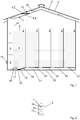
- FIG. 1 A device according to the invention for drying material to be dried is shown, the material to be dried being hay 1 in this case.
- the hay 1 is arranged in a ventilation box 2 between a start area 15 and an end area 16, the hay 1 being divided into a total of five ventilation boxes 2 in the exemplary embodiment shown.
- the ventilation boxes 2 are covered with a roof 3, so that the hay 1 is protected from the weather.
- the hay 1 rests on a box surface 22 in each ventilation box 2.
- Air can flow onto the box surface 22, for example by realizing the box surface 22 through a structural steel grille (not shown) which rests on grate girders (not shown) and is arranged at a certain distance, for example 40 cm, above a floor 23.
- a structural steel grille not shown
- grate girders not shown
- an air duct 21 is formed in the initial region 15, through which air can be blown onto the box surface 22 or into the ventilation box 2.
- each ventilation box 2 is equipped with an air guide flap 20, which either closes the box surface 22 or directs the air onto the box surface 22.
- the air guiding flaps 20 and the air duct 21 therefore act as air guiding means in order to selectively direct the air to a specific ventilation box 2.
- the in Fig. 1 shown device on a fan 4 the arrows in Fig. 1 symbolize possible air flows.
- the air to be blown into the ventilation boxes 2 is first sucked in by means of the fan 4, preferably all of the sucked-in air being sucked in by a dehumidifier 5 in which dehumidifier 5 the air is dehumidified.
- the device has a switching flap 6, which is arranged in the end region 16 and can be moved back and forth between a first position 7 and a second position 8 by means of an electric cylinder 10.
- first position 7 causes the switching flap 6 that air can only be sucked out of the ventilation boxes 2. This air is then fed to the dehumidifier 5 and back into a selected one Blown in ventilation box 2. This means that in this case there is a closed air circuit in the device.
- the air is preferably sucked in completely from the outside or from outside the ventilation boxes 2.
- an air duct 9 is formed under the roof 3 for this.
- the roof 3 is warm due to the solar radiation, the air sucked in from the outside can ultimately be warmed up - ultimately by solar energy.
- good heat conduction of the roof 3 is advantageous, which is why the roof 3 is preferably made from sheet metal, particularly preferably from trapezoidal sheets.
- the changeover flap 6 thus makes it possible to use air which can be sucked in from outside in order to contribute to reaching a desired temperature of the air in the ventilation box 2 or in its start region 15 and / or end region 16, ie to achieve a desired internal temperature.
- Sensors 17 are provided in the start area 15 and in the end area 16 to control the inside temperature and the air humidity in the ventilation box 2 and the drying progress.
- a temperature sensor 24 is provided in the air duct 9 in front of the switching flap 6 in order to measure an outside temperature of the air drawn in from outside.
- a sensor 17 is used instead of the temperature sensor 24 in order to also measure the relative air humidity of the air sucked in from outside directly in the air duct 9. Outside temperature and inside temperature can be compared.
- the outside temperature is compared with the inside temperature, preferably in the end region 16. If the difference between the outside temperature and the inside temperature is greater than a specifiable positive differential temperature threshold, e.g. 3 ° C, the changeover flap 6 is brought into the second position 8 in order to draw in warm air from outside the ventilation box 2.
- a specifiable positive differential temperature threshold e.g. 3 ° C
- the dehumidifier 5 only has to be switched on when the relative air humidity of the air drawn in from outside is more than 50%.
- the changeover flap 6 is brought into the first position 7 in order to prevent the air in the interior of the ventilation box 2 from cooling.
- the air in the ventilation box 2 or the items to be dried can of course also be specifically cooled by moving the changeover flap 6 to the second position 8 if the difference between the outside temperature and the inside temperature is negative.
- the dehumidifier 5 which in Fig. 2 is shown schematically, the arrow indicating the flow direction of the air.
- the dehumidifier 5 has an evaporator 11, in which refrigerant (not shown) is evaporated by the heat of the intake air.
- the intake air is below the dew point cooled, and water condenses on the cold surface of the evaporator 11, from where it runs off or drips off.
- the dehumidifier 5 has a condenser 12 in which the refrigerant condenses and thereby releases latent heat.
- the condenser 12 can be used as a heat source for heating the dehumidified air, in that the air, after it has passed the evaporator 11 and has been dehumidified, is also drawn through the condenser 12.
- the dehumidifier 5 comprises a compressor 13 in order to compress the refrigerant evaporated in the evaporator 11. Since the compressor 13 emits heat here, the compressor 13 is also suitable as an additional heat source, which can also be conveniently arranged between the evaporator 11 and the condenser 12, without significantly impairing the flow of air from the evaporator 11 to the condenser 12, see Fig. 2 .
- the inside temperature can also be raised if the outside temperature is lower than the inside temperature.
- the switching flap 6 is moved into the first position 7 and can be left there, e.g. as long as the inside temperature does not exceed a predeterminable inside temperature threshold.
- the air flow can be influenced by controlling the fan 4, ie the amount of air drawn in and thus the amount of air blown into the ventilation boxes 2 can be regulated.
- air throughputs or quantities of air drawn in should be set from 200 m 3 / h per square meter of box area 22, m B 2 to 600 m 3 / h / m B 2 , preferably 400 m 3 / h / m B 2 .
- the density of the hay 1 can vary - typically between 100 kg / m 3 to 250 kg / m 3 - which is accompanied by a different resistance for the air blown into the ventilation boxes 2.
- the power or the speed of the fan 4 must be controllable, with frequency converters being provided according to the invention for this purpose (not shown).
- Frequency inverters are preferably also used to control the power of dehumidifier 5 or the compressor 13 of dehumidifier 5.
- a sensor 18 for measuring the speed of the air taken in is provided, which is preferably arranged in the dehumidifier 5, behind the evaporator 11. Since the cross section of the dehumidifier 5 through which the air can flow is known, the air throughput results directly from this.
- a pressure sensor 19 is arranged in the initial area 15 to monitor the pressure of the air that is blown into the ventilation boxes 2.
- the monitoring of the pressure in the initial region 15 or the resulting differential pressure between the initial region 15 and the final region 16, which is thus possible, can be used, for example, to ensure that a certain maximum permissible pressure in the initial region 15 or a certain maximum permissible pressure difference is not exceeded. This can occur if the density of the hay 1 is too high and the air throughput too high impaired. If necessary, the fan 4 can thus be regulated accordingly.
- a regulating control unit 14 see Fig. 1 , which is designed as a programmable logic controller.
- the control unit 14 processes the signals from all the sensors 17, the temperature sensor 18 and the pressure sensor 19.
- the design of the control unit 14 as a programmable logic controller also makes it possible to take into account the current amount of hay 1 to be dried and threshold values for inside temperature and outside temperature To specify or adjust air humidity and air throughput.
- the control unit 14 controls the switchover flap 6 and regulates the output of the fan 4 and the ventilator 5.
- the control unit 14 can control the air flaps 20 in order to dry the hay 1 in intervals to enable individual ventilation boxes 2. In this way, the drying of the hay 1 is carried out in a highly automated and optimized manner.
Landscapes
- Engineering & Computer Science (AREA)
- Mechanical Engineering (AREA)
- General Engineering & Computer Science (AREA)
- Life Sciences & Earth Sciences (AREA)
- Microbiology (AREA)
- Environmental Sciences (AREA)
- Health & Medical Sciences (AREA)
- Sustainable Development (AREA)
- Toxicology (AREA)
- Drying Of Solid Materials (AREA)
- Drying Of Gases (AREA)
Claims (6)
- Dispositif pour sécher du foin (1) comprenant un caisson d'aération (2) destiné à recevoir le foin (1), lequel caisson d'aération (2) est couvert par un toit (3), le dispositif comprenant par ailleurs au moins un ventilateur (4), lequel ventilateur (4) peut aspirer de l'air, l'air aspiré pouvant être au moins en partie acheminé vers un déshumidificateur d'air (5) pour enlever l'humidité de l'air, et l'au moins un ventilateur (4) peut enfin souffler l'air à travers le caisson d'aération (2) d'une zone de début (15) à une zone de fin (16) du caisson d'aération (2), dans lequel le foin (1) peut être disposé entre la zone de début (15) et la zone de fin (16) sur une surface de caisson (22) qui peut être parcourue par l'air, dans lequel est prévu un clapet de commutation (6) qui peut être déplacé d'une première position (7) à une deuxième position (8), l'air qui traverse l'au moins un ventilateur (4) pouvant seulement être aspiré hors du caisson d'aération (2) dans la première position (7) pour créer un circuit d'air fermé dans le dispositif, et l'air pouvant être au moins partiellement aspiré à l'extérieur du caisson d'aération (2) dans la deuxième position (8), dans lequel sont prévus plusieurs caissons d'aération (2), de préférence cinq, dans lequel des moyens de guidage de l'air (20, 21) sont prévus pour guider sélectivement l'air vers un caisson d'aération (2) donné, dans lequel est en outre prévue une unité de régulation et de commande (14) réalisée de préférence comme une commande programmable à mémoire, au moyen de laquelle l'au moins un ventilateur (4) et le déshumidificateur d'air (5) peuvent être commandés et/ou régulés, et dans lequel les moyens de guidage de l'air comprennent au moins un volet de guidage de l'air (20) qui peut être actionné au moyen de l'unité de régulation et de commande (14), caractérisé en ce que le clapet de commutation (6) peut être actionné et/ou régulé au moyen de l'unité de régulation et de commande (14) et en ce que l'au moins un volet de guidage de l'air (20) peut être actionné au moyen de l'unité de régulation et de commande (14) de façon à sécher le foin (1) de façon intermittente dans les différents caissons d'aération (2), l'au moins un volet de guidage de l'air (20) pouvant être actionné au moyen de l'unité de régulation et de commande (14) de façon à ne pas sécher le foin (1) dans l'un des caissons d'aération (2) pendant un premier intervalle de temps et à le sécher pendant un deuxième intervalle de temps suivant par le soufflage d'air dans ce caisson d'aération (2).
- Dispositif selon la revendication 1, caractérisé en ce que pour chaque caisson d'aération (2), il est prévu un volet de guidage de l'air (20) qui peut être actionné au moyen de l'unité de régulation et de commande (14).
- Dispositif selon l'une des revendications 1 à 2, caractérisé en ce que l'au moins un volet de guidage de l'air (20) peut être actionné au moyen de l'unité de régulation et de commande (14) de façon à ne souffler l'air que dans l'un des caissons d'aération et à guider l'air dans le caisson d'aération suivant et à l'y souffler après un certain temps pouvant être prédéterminé.
- Dispositif selon l'une des revendications 1 à 3, caractérisé en ce que le premier intervalle de temps dure au maximum 2 heures.
- Dispositif selon l'une des revendications 1 à 4, caractérisé en ce que les différents caissons d'aération (2) sont conçus pour le séchage de matières à sécher différentes.
- Dispositif selon l'une des revendications 1 à 5, caractérisé en ce qu'un capteur (18) est prévu dans le déshumidificateur d'air (5) en aval de l'évaporateur (11) pour mesurer la vitesse de l'air aspiré.
Applications Claiming Priority (2)
| Application Number | Priority Date | Filing Date | Title |
|---|---|---|---|
| AT3912013 | 2013-11-22 | ||
| EP14185349.9A EP2876395B1 (fr) | 2013-11-22 | 2014-09-18 | Dispositif et procédé de séchage de matières à sécher |
Related Parent Applications (2)
| Application Number | Title | Priority Date | Filing Date |
|---|---|---|---|
| EP14185349.9A Division-Into EP2876395B1 (fr) | 2013-11-22 | 2014-09-18 | Dispositif et procédé de séchage de matières à sécher |
| EP14185349.9A Division EP2876395B1 (fr) | 2013-11-22 | 2014-09-18 | Dispositif et procédé de séchage de matières à sécher |
Publications (2)
| Publication Number | Publication Date |
|---|---|
| EP3187807A1 EP3187807A1 (fr) | 2017-07-05 |
| EP3187807B1 true EP3187807B1 (fr) | 2020-04-15 |
Family
ID=51627950
Family Applications (2)
| Application Number | Title | Priority Date | Filing Date |
|---|---|---|---|
| EP17156316.6A Active EP3187807B1 (fr) | 2013-11-22 | 2014-09-18 | Dispositif de séchage de foin |
| EP14185349.9A Active EP2876395B1 (fr) | 2013-11-22 | 2014-09-18 | Dispositif et procédé de séchage de matières à sécher |
Family Applications After (1)
| Application Number | Title | Priority Date | Filing Date |
|---|---|---|---|
| EP14185349.9A Active EP2876395B1 (fr) | 2013-11-22 | 2014-09-18 | Dispositif et procédé de séchage de matières à sécher |
Country Status (3)
| Country | Link |
|---|---|
| EP (2) | EP3187807B1 (fr) |
| AT (1) | AT15376U3 (fr) |
| DE (1) | DE202014010983U1 (fr) |
Cited By (1)
| Publication number | Priority date | Publication date | Assignee | Title |
|---|---|---|---|---|
| EP4317878A1 (fr) * | 2022-08-02 | 2024-02-07 | J+W Liegenschaftsverwaltungs GmbH | Procédé de commande d'une installation de séchage |
Families Citing this family (12)
| Publication number | Priority date | Publication date | Assignee | Title |
|---|---|---|---|---|
| CN105387696A (zh) * | 2015-12-16 | 2016-03-09 | 芜湖杰诺科技有限公司 | 一种阀门烘干箱 |
| IT201700017699A1 (it) * | 2017-02-16 | 2018-08-16 | Marcello Galvanin | Essiccatoio per filato di rocche o matasse con ricircolo dell’aria calda |
| CN106818082A (zh) * | 2017-03-13 | 2017-06-13 | 云南省粮油科学研究院(云南省粮油产品质量监督检验测试中心) | 一种新型粮仓 |
| CN107580881A (zh) * | 2017-10-10 | 2018-01-16 | 写义明 | 一种颗粒物料储存装置 |
| DE102019116899A1 (de) * | 2019-06-24 | 2020-12-24 | Lasco Heutechnik Gmbh | Trocknungsvorrichtung und -verfahren |
| CN110463451B (zh) * | 2019-09-18 | 2025-03-11 | 农业农村部规划设计研究院 | 一种融自然通风与太阳能驱动通风为一体的储粮装置 |
| CN110771359A (zh) * | 2019-11-26 | 2020-02-11 | 湖州赛龙网络技术有限公司 | 一种粮食仓储用的通风风道结构 |
| CN110959386A (zh) * | 2019-12-02 | 2020-04-07 | 徐州鲜品湾电子商务有限公司 | 一种通风型谷物仓 |
| CN111076529A (zh) * | 2019-12-31 | 2020-04-28 | 巢湖市金辉自控设备有限公司 | 一种管材烘干设备主机系统及其使用方法 |
| CN114061274A (zh) * | 2021-10-22 | 2022-02-18 | 佛山市瑞丰恒业机械有限公司 | 一种烘炉自动节能控制系统 |
| CN114631433B (zh) * | 2022-04-13 | 2023-09-05 | 安徽嘉禾粮食机械有限公司 | 一种用于谷物贮存的拼装式粮仓 |
| CN119631730B (zh) * | 2025-02-18 | 2025-06-13 | 台州市一鸣机械股份有限公司 | 一种用于装配式金属粮仓的水冷式除湿控温装置 |
Family Cites Families (12)
| Publication number | Priority date | Publication date | Assignee | Title |
|---|---|---|---|---|
| US1989530A (en) | 1932-10-14 | 1935-01-29 | James Mfg Co | Method and apparatus for the storage, curing, and preservation of hay |
| US4043051A (en) * | 1975-02-24 | 1977-08-23 | Delbert Lussenden | Method and apparatus for drying grain |
| US4050164A (en) * | 1976-03-08 | 1977-09-27 | Cromwell B. Campbell | Grain dryer construction |
| JPS61276683A (ja) * | 1985-05-30 | 1986-12-06 | 豊国工業株式会社 | 農産物等の乾燥装置 |
| JP3005777B2 (ja) * | 1991-10-30 | 2000-02-07 | ヤンマー農機株式会社 | 穀物貯蔵施設 |
| US5325604A (en) * | 1992-12-17 | 1994-07-05 | The University Of Tennessee Research Corporation | Automatic control system for wood drying kiln |
| US5595000A (en) * | 1995-01-17 | 1997-01-21 | U.S. Natural Resources, Inc. | No-vent dry kiln |
| US5893218A (en) * | 1997-04-15 | 1999-04-13 | Pioneer Hi-Bred International, Inc. | Seed dryer with automatic control of temperature air flow direction and rate |
| FR2843957B1 (fr) * | 2002-08-28 | 2004-10-22 | Ondeo Degremont | Installation de sechage de dechets, notamment de boues d'epuration d'eaux |
| US8726535B2 (en) * | 2008-12-16 | 2014-05-20 | Pioneer Hi Bred International Inc | Method, apparatus and system for controlling heated air drying |
| GB2463747B (en) | 2009-04-27 | 2010-08-25 | Vegetable Consultancy Services | Ventilation system for a perishable goods store |
| US20110252663A1 (en) * | 2010-04-19 | 2011-10-20 | Global Seed Dryer Solutions, LLC | Agricultural material dryer |
-
2014
- 2014-09-18 AT ATGM50029/2017U patent/AT15376U3/de not_active IP Right Cessation
- 2014-09-18 DE DE202014010983.4U patent/DE202014010983U1/de not_active Expired - Lifetime
- 2014-09-18 EP EP17156316.6A patent/EP3187807B1/fr active Active
- 2014-09-18 EP EP14185349.9A patent/EP2876395B1/fr active Active
Non-Patent Citations (1)
| Title |
|---|
| None * |
Cited By (1)
| Publication number | Priority date | Publication date | Assignee | Title |
|---|---|---|---|---|
| EP4317878A1 (fr) * | 2022-08-02 | 2024-02-07 | J+W Liegenschaftsverwaltungs GmbH | Procédé de commande d'une installation de séchage |
Also Published As
| Publication number | Publication date |
|---|---|
| DE202014010983U1 (de) | 2017-03-02 |
| EP2876395B1 (fr) | 2020-02-26 |
| EP3187807A1 (fr) | 2017-07-05 |
| EP2876395A1 (fr) | 2015-05-27 |
| AT15376U3 (de) | 2018-05-15 |
| AT15376U2 (de) | 2017-07-15 |
Similar Documents
| Publication | Publication Date | Title |
|---|---|---|
| EP3187807B1 (fr) | Dispositif de séchage de foin | |
| EP2587203B1 (fr) | Séchoir à bande | |
| EP2876396B1 (fr) | Procédé de séchage de matières à sécher | |
| DE2541070B2 (de) | Verfahren zum kontinuierlichen Kompostieren von organischen Abfällen und/oder Klärschlamm und Einrichtung zur Durchführung des Verfahrens | |
| WO2008119471A1 (fr) | Procédé et dispositif pour sécher des pièces moulées | |
| DE102008046299B4 (de) | Verfahren und Vorrichtung zum Trocknen von Biomasse | |
| EP2886984A2 (fr) | Procédé de séchage et/ou de cristallisation de produits en vrac et installation d'exécution d'un tel procédé | |
| DE102009007789B3 (de) | Trocknungsanlage für landwirtschaftliche Körnerfrüchte | |
| EP2993433B1 (fr) | Dispositif de pre-sechage et installation de sechage | |
| AT514695B1 (de) | Vorrichtung und Verfahren zum Trocknen von Trocknungsgut | |
| EP3317601B1 (fr) | Méthode et appareil pour le traitement et le séchage de matériaux solides en forme de particules | |
| DE2546494C3 (de) | Verfahren zur Langzeitkonservierung von Getreide | |
| DE202013101746U1 (de) | Trockner zum Trocknen von Trocknungsgut mittels warmer Trocknungsluft | |
| DE102004045255B4 (de) | Humidor | |
| DE102012102130B4 (de) | Schubbodendurchlauftrockner | |
| EP2674713A2 (fr) | Installation de séchage pour produits en vrac | |
| DE3616411A1 (de) | Verfahren und vorrichtung zur konvektiven trocknung und kuehlung rieselfaehiger schuettgueter | |
| DE1815125C (de) | Anlage zur Trocknung von auf einem Erntewagen gestapelten landwirtschaftlichen Produkten | |
| DE202015104924U1 (de) | Pelletiervorrichtung | |
| AT514802B1 (de) | Luftentfeuchter zum Entfeuchten von Luft zur Trocknung von Heu | |
| DE1778238A1 (de) | Anlage zur Trocknung landwirtschaftlicher Produkte | |
| AT10181U1 (de) | Vorrichtung zum trocknen von schüttgut und verfahren zum betrieb einer solchen vorrichtung | |
| DE1815125A1 (de) | Anlage zur Trocknung von landwirtschaftlichen Produkten auf Wagen | |
| DE202015106430U1 (de) | Mobiles Trocknungssystem | |
| DE102017009465A1 (de) | Einrichtung und Verfahren zur Aufbereitung von Biomasse |
Legal Events
| Date | Code | Title | Description |
|---|---|---|---|
| PUAI | Public reference made under article 153(3) epc to a published international application that has entered the european phase |
Free format text: ORIGINAL CODE: 0009012 |
|
| STAA | Information on the status of an ep patent application or granted ep patent |
Free format text: STATUS: THE APPLICATION HAS BEEN PUBLISHED |
|
| AC | Divisional application: reference to earlier application |
Ref document number: 2876395 Country of ref document: EP Kind code of ref document: P |
|
| AK | Designated contracting states |
Kind code of ref document: A1 Designated state(s): AL AT BE BG CH CY CZ DE DK EE ES FI FR GB GR HR HU IE IS IT LI LT LU LV MC MK MT NL NO PL PT RO RS SE SI SK SM TR |
|
| STAA | Information on the status of an ep patent application or granted ep patent |
Free format text: STATUS: REQUEST FOR EXAMINATION WAS MADE |
|
| 17P | Request for examination filed |
Effective date: 20171211 |
|
| RBV | Designated contracting states (corrected) |
Designated state(s): AL AT BE BG CH CY CZ DE DK EE ES FI FR GB GR HR HU IE IS IT LI LT LU LV MC MK MT NL NO PL PT RO RS SE SI SK SM TR |
|
| STAA | Information on the status of an ep patent application or granted ep patent |
Free format text: STATUS: EXAMINATION IS IN PROGRESS |
|
| 17Q | First examination report despatched |
Effective date: 20180622 |
|
| GRAP | Despatch of communication of intention to grant a patent |
Free format text: ORIGINAL CODE: EPIDOSNIGR1 |
|
| STAA | Information on the status of an ep patent application or granted ep patent |
Free format text: STATUS: GRANT OF PATENT IS INTENDED |
|
| INTG | Intention to grant announced |
Effective date: 20190603 |
|
| GRAJ | Information related to disapproval of communication of intention to grant by the applicant or resumption of examination proceedings by the epo deleted |
Free format text: ORIGINAL CODE: EPIDOSDIGR1 |
|
| STAA | Information on the status of an ep patent application or granted ep patent |
Free format text: STATUS: EXAMINATION IS IN PROGRESS |
|
| GRAP | Despatch of communication of intention to grant a patent |
Free format text: ORIGINAL CODE: EPIDOSNIGR1 |
|
| INTC | Intention to grant announced (deleted) | ||
| RAP1 | Party data changed (applicant data changed or rights of an application transferred) |
Owner name: HEUTROCKNUNG SR GMBH |
|
| STAA | Information on the status of an ep patent application or granted ep patent |
Free format text: STATUS: GRANT OF PATENT IS INTENDED |
|
| INTG | Intention to grant announced |
Effective date: 20191114 |
|
| GRAS | Grant fee paid |
Free format text: ORIGINAL CODE: EPIDOSNIGR3 |
|
| GRAA | (expected) grant |
Free format text: ORIGINAL CODE: 0009210 |
|
| STAA | Information on the status of an ep patent application or granted ep patent |
Free format text: STATUS: THE PATENT HAS BEEN GRANTED |
|
| AC | Divisional application: reference to earlier application |
Ref document number: 2876395 Country of ref document: EP Kind code of ref document: P |
|
| AK | Designated contracting states |
Kind code of ref document: B1 Designated state(s): AL AT BE BG CH CY CZ DE DK EE ES FI FR GB GR HR HU IE IS IT LI LT LU LV MC MK MT NL NO PL PT RO RS SE SI SK SM TR |
|
| REG | Reference to a national code |
Ref country code: CH Ref legal event code: EP |
|
| REG | Reference to a national code |
Ref country code: DE Ref legal event code: R096 Ref document number: 502014014013 Country of ref document: DE |
|
| REG | Reference to a national code |
Ref country code: IE Ref legal event code: FG4D Free format text: LANGUAGE OF EP DOCUMENT: GERMAN |
|
| REG | Reference to a national code |
Ref country code: AT Ref legal event code: REF Ref document number: 1257800 Country of ref document: AT Kind code of ref document: T Effective date: 20200515 |
|
| REG | Reference to a national code |
Ref country code: NL Ref legal event code: MP Effective date: 20200415 |
|
| REG | Reference to a national code |
Ref country code: LT Ref legal event code: MG4D |
|
| PG25 | Lapsed in a contracting state [announced via postgrant information from national office to epo] |
Ref country code: SE Free format text: LAPSE BECAUSE OF FAILURE TO SUBMIT A TRANSLATION OF THE DESCRIPTION OR TO PAY THE FEE WITHIN THE PRESCRIBED TIME-LIMIT Effective date: 20200415 Ref country code: IS Free format text: LAPSE BECAUSE OF FAILURE TO SUBMIT A TRANSLATION OF THE DESCRIPTION OR TO PAY THE FEE WITHIN THE PRESCRIBED TIME-LIMIT Effective date: 20200815 Ref country code: FI Free format text: LAPSE BECAUSE OF FAILURE TO SUBMIT A TRANSLATION OF THE DESCRIPTION OR TO PAY THE FEE WITHIN THE PRESCRIBED TIME-LIMIT Effective date: 20200415 Ref country code: PT Free format text: LAPSE BECAUSE OF FAILURE TO SUBMIT A TRANSLATION OF THE DESCRIPTION OR TO PAY THE FEE WITHIN THE PRESCRIBED TIME-LIMIT Effective date: 20200817 Ref country code: GR Free format text: LAPSE BECAUSE OF FAILURE TO SUBMIT A TRANSLATION OF THE DESCRIPTION OR TO PAY THE FEE WITHIN THE PRESCRIBED TIME-LIMIT Effective date: 20200716 Ref country code: NO Free format text: LAPSE BECAUSE OF FAILURE TO SUBMIT A TRANSLATION OF THE DESCRIPTION OR TO PAY THE FEE WITHIN THE PRESCRIBED TIME-LIMIT Effective date: 20200715 Ref country code: NL Free format text: LAPSE BECAUSE OF FAILURE TO SUBMIT A TRANSLATION OF THE DESCRIPTION OR TO PAY THE FEE WITHIN THE PRESCRIBED TIME-LIMIT Effective date: 20200415 Ref country code: LT Free format text: LAPSE BECAUSE OF FAILURE TO SUBMIT A TRANSLATION OF THE DESCRIPTION OR TO PAY THE FEE WITHIN THE PRESCRIBED TIME-LIMIT Effective date: 20200415 |
|
| PG25 | Lapsed in a contracting state [announced via postgrant information from national office to epo] |
Ref country code: BG Free format text: LAPSE BECAUSE OF FAILURE TO SUBMIT A TRANSLATION OF THE DESCRIPTION OR TO PAY THE FEE WITHIN THE PRESCRIBED TIME-LIMIT Effective date: 20200715 Ref country code: RS Free format text: LAPSE BECAUSE OF FAILURE TO SUBMIT A TRANSLATION OF THE DESCRIPTION OR TO PAY THE FEE WITHIN THE PRESCRIBED TIME-LIMIT Effective date: 20200415 Ref country code: HR Free format text: LAPSE BECAUSE OF FAILURE TO SUBMIT A TRANSLATION OF THE DESCRIPTION OR TO PAY THE FEE WITHIN THE PRESCRIBED TIME-LIMIT Effective date: 20200415 Ref country code: LV Free format text: LAPSE BECAUSE OF FAILURE TO SUBMIT A TRANSLATION OF THE DESCRIPTION OR TO PAY THE FEE WITHIN THE PRESCRIBED TIME-LIMIT Effective date: 20200415 |
|
| PG25 | Lapsed in a contracting state [announced via postgrant information from national office to epo] |
Ref country code: AL Free format text: LAPSE BECAUSE OF FAILURE TO SUBMIT A TRANSLATION OF THE DESCRIPTION OR TO PAY THE FEE WITHIN THE PRESCRIBED TIME-LIMIT Effective date: 20200415 |
|
| REG | Reference to a national code |
Ref country code: DE Ref legal event code: R097 Ref document number: 502014014013 Country of ref document: DE |
|
| PG25 | Lapsed in a contracting state [announced via postgrant information from national office to epo] |
Ref country code: SM Free format text: LAPSE BECAUSE OF FAILURE TO SUBMIT A TRANSLATION OF THE DESCRIPTION OR TO PAY THE FEE WITHIN THE PRESCRIBED TIME-LIMIT Effective date: 20200415 Ref country code: EE Free format text: LAPSE BECAUSE OF FAILURE TO SUBMIT A TRANSLATION OF THE DESCRIPTION OR TO PAY THE FEE WITHIN THE PRESCRIBED TIME-LIMIT Effective date: 20200415 Ref country code: RO Free format text: LAPSE BECAUSE OF FAILURE TO SUBMIT A TRANSLATION OF THE DESCRIPTION OR TO PAY THE FEE WITHIN THE PRESCRIBED TIME-LIMIT Effective date: 20200415 Ref country code: IT Free format text: LAPSE BECAUSE OF FAILURE TO SUBMIT A TRANSLATION OF THE DESCRIPTION OR TO PAY THE FEE WITHIN THE PRESCRIBED TIME-LIMIT Effective date: 20200415 Ref country code: DK Free format text: LAPSE BECAUSE OF FAILURE TO SUBMIT A TRANSLATION OF THE DESCRIPTION OR TO PAY THE FEE WITHIN THE PRESCRIBED TIME-LIMIT Effective date: 20200415 Ref country code: ES Free format text: LAPSE BECAUSE OF FAILURE TO SUBMIT A TRANSLATION OF THE DESCRIPTION OR TO PAY THE FEE WITHIN THE PRESCRIBED TIME-LIMIT Effective date: 20200415 Ref country code: CZ Free format text: LAPSE BECAUSE OF FAILURE TO SUBMIT A TRANSLATION OF THE DESCRIPTION OR TO PAY THE FEE WITHIN THE PRESCRIBED TIME-LIMIT Effective date: 20200415 |
|
| PLBE | No opposition filed within time limit |
Free format text: ORIGINAL CODE: 0009261 |
|
| STAA | Information on the status of an ep patent application or granted ep patent |
Free format text: STATUS: NO OPPOSITION FILED WITHIN TIME LIMIT |
|
| PG25 | Lapsed in a contracting state [announced via postgrant information from national office to epo] |
Ref country code: PL Free format text: LAPSE BECAUSE OF FAILURE TO SUBMIT A TRANSLATION OF THE DESCRIPTION OR TO PAY THE FEE WITHIN THE PRESCRIBED TIME-LIMIT Effective date: 20200415 Ref country code: SK Free format text: LAPSE BECAUSE OF FAILURE TO SUBMIT A TRANSLATION OF THE DESCRIPTION OR TO PAY THE FEE WITHIN THE PRESCRIBED TIME-LIMIT Effective date: 20200415 |
|
| 26N | No opposition filed |
Effective date: 20210118 |
|
| PG25 | Lapsed in a contracting state [announced via postgrant information from national office to epo] |
Ref country code: MC Free format text: LAPSE BECAUSE OF FAILURE TO SUBMIT A TRANSLATION OF THE DESCRIPTION OR TO PAY THE FEE WITHIN THE PRESCRIBED TIME-LIMIT Effective date: 20200415 |
|
| REG | Reference to a national code |
Ref country code: CH Ref legal event code: PL |
|
| GBPC | Gb: european patent ceased through non-payment of renewal fee |
Effective date: 20200918 |
|
| PG25 | Lapsed in a contracting state [announced via postgrant information from national office to epo] |
Ref country code: SI Free format text: LAPSE BECAUSE OF FAILURE TO SUBMIT A TRANSLATION OF THE DESCRIPTION OR TO PAY THE FEE WITHIN THE PRESCRIBED TIME-LIMIT Effective date: 20200415 |
|
| REG | Reference to a national code |
Ref country code: BE Ref legal event code: MM Effective date: 20200930 |
|
| PG25 | Lapsed in a contracting state [announced via postgrant information from national office to epo] |
Ref country code: LU Free format text: LAPSE BECAUSE OF NON-PAYMENT OF DUE FEES Effective date: 20200918 |
|
| PG25 | Lapsed in a contracting state [announced via postgrant information from national office to epo] |
Ref country code: CH Free format text: LAPSE BECAUSE OF NON-PAYMENT OF DUE FEES Effective date: 20200930 Ref country code: BE Free format text: LAPSE BECAUSE OF NON-PAYMENT OF DUE FEES Effective date: 20200930 Ref country code: LI Free format text: LAPSE BECAUSE OF NON-PAYMENT OF DUE FEES Effective date: 20200930 Ref country code: GB Free format text: LAPSE BECAUSE OF NON-PAYMENT OF DUE FEES Effective date: 20200918 Ref country code: IE Free format text: LAPSE BECAUSE OF NON-PAYMENT OF DUE FEES Effective date: 20200918 |
|
| PG25 | Lapsed in a contracting state [announced via postgrant information from national office to epo] |
Ref country code: TR Free format text: LAPSE BECAUSE OF FAILURE TO SUBMIT A TRANSLATION OF THE DESCRIPTION OR TO PAY THE FEE WITHIN THE PRESCRIBED TIME-LIMIT Effective date: 20200415 Ref country code: MT Free format text: LAPSE BECAUSE OF FAILURE TO SUBMIT A TRANSLATION OF THE DESCRIPTION OR TO PAY THE FEE WITHIN THE PRESCRIBED TIME-LIMIT Effective date: 20200415 Ref country code: CY Free format text: LAPSE BECAUSE OF FAILURE TO SUBMIT A TRANSLATION OF THE DESCRIPTION OR TO PAY THE FEE WITHIN THE PRESCRIBED TIME-LIMIT Effective date: 20200415 |
|
| PG25 | Lapsed in a contracting state [announced via postgrant information from national office to epo] |
Ref country code: MK Free format text: LAPSE BECAUSE OF FAILURE TO SUBMIT A TRANSLATION OF THE DESCRIPTION OR TO PAY THE FEE WITHIN THE PRESCRIBED TIME-LIMIT Effective date: 20200415 |
|
| PGFP | Annual fee paid to national office [announced via postgrant information from national office to epo] |
Ref country code: DE Payment date: 20220929 Year of fee payment: 9 |
|
| PGFP | Annual fee paid to national office [announced via postgrant information from national office to epo] |
Ref country code: FR Payment date: 20220927 Year of fee payment: 9 |
|
| P01 | Opt-out of the competence of the unified patent court (upc) registered |
Effective date: 20230629 |
|
| REG | Reference to a national code |
Ref country code: DE Ref legal event code: R119 Ref document number: 502014014013 Country of ref document: DE |
|
| PG25 | Lapsed in a contracting state [announced via postgrant information from national office to epo] |
Ref country code: FR Free format text: LAPSE BECAUSE OF NON-PAYMENT OF DUE FEES Effective date: 20230930 Ref country code: DE Free format text: LAPSE BECAUSE OF NON-PAYMENT OF DUE FEES Effective date: 20240403 |
|
| PGFP | Annual fee paid to national office [announced via postgrant information from national office to epo] |
Ref country code: AT Payment date: 20250924 Year of fee payment: 12 |