EP3189129B1 - Dispositifs et procédés de dissociation d'un échantillon de tissu biologique - Google Patents
Dispositifs et procédés de dissociation d'un échantillon de tissu biologique Download PDFInfo
- Publication number
- EP3189129B1 EP3189129B1 EP15838851.2A EP15838851A EP3189129B1 EP 3189129 B1 EP3189129 B1 EP 3189129B1 EP 15838851 A EP15838851 A EP 15838851A EP 3189129 B1 EP3189129 B1 EP 3189129B1
- Authority
- EP
- European Patent Office
- Prior art keywords
- tissue
- housing
- actuator
- distal end
- dissociator
- Prior art date
- Legal status (The legal status is an assumption and is not a legal conclusion. Google has not performed a legal analysis and makes no representation as to the accuracy of the status listed.)
- Active
Links
Images






Classifications
-
- B—PERFORMING OPERATIONS; TRANSPORTING
- B02—CRUSHING, PULVERISING, OR DISINTEGRATING; PREPARATORY TREATMENT OF GRAIN FOR MILLING
- B02C—CRUSHING, PULVERISING, OR DISINTEGRATING IN GENERAL; MILLING GRAIN
- B02C1/00—Crushing or disintegrating by reciprocating members
- B02C1/14—Stamping mills
-
- G—PHYSICS
- G01—MEASURING; TESTING
- G01N—INVESTIGATING OR ANALYSING MATERIALS BY DETERMINING THEIR CHEMICAL OR PHYSICAL PROPERTIES
- G01N1/00—Sampling; Preparing specimens for investigation
- G01N1/28—Preparing specimens for investigation including physical details of (bio-)chemical methods covered elsewhere, e.g. G01N33/50, C12Q
- G01N1/286—Preparing specimens for investigation including physical details of (bio-)chemical methods covered elsewhere, e.g. G01N33/50, C12Q involving mechanical work, e.g. chopping, disintegrating, compacting, homogenising
-
- B—PERFORMING OPERATIONS; TRANSPORTING
- B02—CRUSHING, PULVERISING, OR DISINTEGRATING; PREPARATORY TREATMENT OF GRAIN FOR MILLING
- B02C—CRUSHING, PULVERISING, OR DISINTEGRATING IN GENERAL; MILLING GRAIN
- B02C18/00—Disintegrating by knives or other cutting or tearing members which chop material into fragments
- B02C18/02—Disintegrating by knives or other cutting or tearing members which chop material into fragments with reciprocating knives
-
- B—PERFORMING OPERATIONS; TRANSPORTING
- B02—CRUSHING, PULVERISING, OR DISINTEGRATING; PREPARATORY TREATMENT OF GRAIN FOR MILLING
- B02C—CRUSHING, PULVERISING, OR DISINTEGRATING IN GENERAL; MILLING GRAIN
- B02C19/00—Other disintegrating devices or methods
- B02C19/08—Pestle and mortar
-
- C—CHEMISTRY; METALLURGY
- C12—BIOCHEMISTRY; BEER; SPIRITS; WINE; VINEGAR; MICROBIOLOGY; ENZYMOLOGY; MUTATION OR GENETIC ENGINEERING
- C12M—APPARATUS FOR ENZYMOLOGY OR MICROBIOLOGY; APPARATUS FOR CULTURING MICROORGANISMS FOR PRODUCING BIOMASS, FOR GROWING CELLS OR FOR OBTAINING FERMENTATION OR METABOLIC PRODUCTS, i.e. BIOREACTORS OR FERMENTERS
- C12M45/00—Means for pre-treatment of biological substances
- C12M45/02—Means for pre-treatment of biological substances by mechanical forces; Stirring; Trituration; Comminuting
-
- G—PHYSICS
- G01—MEASURING; TESTING
- G01N—INVESTIGATING OR ANALYSING MATERIALS BY DETERMINING THEIR CHEMICAL OR PHYSICAL PROPERTIES
- G01N1/00—Sampling; Preparing specimens for investigation
- G01N1/28—Preparing specimens for investigation including physical details of (bio-)chemical methods covered elsewhere, e.g. G01N33/50, C12Q
- G01N1/286—Preparing specimens for investigation including physical details of (bio-)chemical methods covered elsewhere, e.g. G01N33/50, C12Q involving mechanical work, e.g. chopping, disintegrating, compacting, homogenising
- G01N2001/2866—Grinding or homogeneising
Definitions
- Tissue processing to achieve desired single cell compositions is commonly accomplished by mechanical disruption followed by enzymatic digestion.
- efficiency and effectiveness of enzymatic digestion is proportional to the surface area of the tissue-enzyme interface. Increased surface area can be achieved by mincing the tissue by mechanical means prior to enzymatic exposure. Tissue dissociation can often require laborious separation protocols and numerous manipulations of the tissue in order to separate the desired tissue sample from other biological material.
- tissue pieces that can have a wide range of size distribution varying enormously from one sample to the next or one operator to the next.
- time required to process certain sample types may require a different extent of dissociation than others (e.g., cancerous or necrotic tissue), making dissociation of complex biological samples difficult and inefficient.
- Reference US 2004/018575 A1 discloses a device and method for the collection and preparation of a sample for direct analysis of an analyte.
- Reference US 2009/084202 A1 discloses a trituration vessel that enables highly efficient triturating of even hard samples.
- Reference US 2012/201726 A1 discloses a reagent preparation and dispensing device.
- Reference US 2002/197631 A1 discloses a device and a method for the homogenization, processing, detection and analysis of biological samples.
- Reference FR 1 270 511 A discloses a method and apparatus for separation of Endo cellular constituent tissue.
- Reference US 4 350 768 A discloses a method and apparatus for the preparation of a liquid suspension of single, independent tissue cells.
- Reference US 6 209 439 B1 discloses a garlic cutter having a housing and a beaker shaped structure to receive garlic rotatably in the housing.
- Reference EP 2 191 750 A2 discloses a device for pressing and/or cutting fresh herbs or spices such as garlic.
- Tissue dissociators configured to disrupt a biological tissue sample.
- Tissue dissociators according to the invention include a housing having a distal end and a proximal end, a cutting blade positioned at the distal end of the housing and a tissue actuator configured to be displaced along a longitudinal axis within the housing.
- Tissue actuators include a fluid reservoir which extends from a proximal end to a distal end of the tissue actuator and a plunger configured to be displaced along a longitudinal axis within the fluid reservoir.
- aspects of the disclosure also include methods for dissociating a biological tissue sample.
- Methods according to the invention include inserting a biological tissue into a tissue dissociator housing, pressing the biological tissue against cutting blades positioned at the distal end of the housing by displacing the tissue actuator from the proximal end to the distal end of the housing in a manner sufficient to produce a dissociated biological tissue sample having components of identical shape and size.
- Kits which include a housing, a cutting blade and a tissue actuator configured to be displaced along a longitudinal axis within the housing are also provided.
- tissue dissociators configured to disrupt a biological tissue sample. Aspects of the tissue dissociators may include a housing having a distal end and a proximal end, a cutting blade positioned at the distal end of the housing and a tissue actuator configured to be displaced along a longitudinal axis within the housing. Also provided are methods of using the tissue dissociators, as well as kits including the tissue dissociators.
- tissue dissociators configured to disrupt a biological tissue sample.
- tissue dissociators that include a housing having a distal end and a proximal end, a cutting blade positioned at the distal end of the housing and a tissue actuator configured to be displaced along a longitudinal axis within the housing are first described in greater detail. Next, methods for preparing a dissociated biological tissue sample with the subject tissue dissociators are described. Kits for preparing a dissociated biological tissue sample are also provided.
- aspects of the present disclosure include a tissue dissociator configured to dissociate a biological tissue sample.
- tissue dissociator is used herein in its conventional sense to refer to breaking up and separating the biological tissue sample into a plurality of smaller tissue fragments, such as into 2 or more tissue fragments, such as 5 or more, such as 10 or more, such as 25 or more, such as 50 or more and including breaking up and separating a biological tissue sample into 100 or more tissue fragments.
- a given biological tissue sample is considered dissociated, if following dissociation, 2 or more, such as 5 or more, such as 10 or more, such as 25 or more, such as 50 or more, such as 100 or more tissue fragments which were originally stably associated with each other are no longer stably associated with other, i.e., they can be freely moved relative to each other.
- methods include breaking up an organ or tissue in order to collect the smaller components which collectively make up the organ or tissue.
- biological tissue sample is used in its conventional sense to refer to a whole organism, plant, fungi or a subset of tissues or component parts of the organism.
- Biological tissue samples may be obtained from an in vitro source (e.g., tissue grown in laboratory culture) or from an in vivo source (e.g., a mammalian subject, a human subject, etc.).
- the tissue sample is obtained from an in vitro source.
- the biological tissue sample is obtained from an in vivo source, where in some instances, tissues derived from a subject are cultured, stored, or manipulated prior to evaluation.
- In vivo sources include living multi-cellular organisms and can yield non-diagnostic or diagnostic tissue samples.
- the source of the tissue sample is a "mammal” or “mammalian”, where these terms are used broadly to describe organisms which are within the class mammalia, including the orders carnivore (e.g., dogs and cats), rodentia (e.g., mice, guinea pigs, and rats), and primates (e.g., humans, chimpanzees, and monkeys). In some instances, the subjects are humans.
- Biological tissue samples may include tissue from human subjects of both genders and at any stage of development (i.e., neonates, infant, juvenile, adolescent, adult), where in certain embodiments the human subject is a juvenile, adolescent or adult.
- non-human subjects such as, but not limited to, birds, mice, rats, dogs, cats, livestock and horses.
- biological tissue samples include tissue from a component part of a human subject, such as organs, including but not limited to integumentary tissue (e.g. sections of the skin), oral tissue (e.g., buccal, tongue, palatal, gums), respiratory tissue (e.g., pharynx, larynx, trachea, bronchi, lungs, diaphragm) gastrointestinal tissue (e.g., esophagus, stomach, liver, gallbladder, pancreas, intestines, colon, rectum and anus.), cardiovascular tissue (e.g., heart, blood vessels), endocrine tissue (e.g., hypothalamus, pituitary gland, pineal body or pineal gland, thyroid, parathyroids, adrenal glands) and genitourinary tissue (kidneys, ureters, bladder, urethra, ovaries, fallopian tubes, uterus, vagina, mammary glands, testes,
- Tissue dissociator devices of interest may be configured to dissociate biological tissue samples of varying size, depending on the type of tissue and size of housing (as described in greater detail below) where in some instances the length of biological tissue samples may range from 1 cm to 50 cm, such as from 2.5 cm to 45 cm, such as from 5 cm to 40 cm, such as from 7.5 cm to 35 cm and including from 10 cm to 25 cm and the width of biological tissue samples may range from 1 cm to 50 cm, such as from 2.5 cm to 45 cm, such as from 5 cm to 40 cm, such as from 7.5 cm to 35 cm and including from 10 cm to 25 cm.
- the thickness of biological tissue samples may also vary, ranging from 0.001 mm to 50 mm, such as from 0.005 mm to 25 mm, such as from 0.01 mm to 15 mm, such as from 0.05 mm to 10 mm and including from 0.1 mm to 5 mm.
- tissue dissociator devices of interest may be configured to dissociate biological tissue samples having a surface area ranging from 0.01 to 100 cm 2 , such as 0.05 to 50 cm 2 , such as 0.1 to 25 cm 2 , such as 0.5 to 15 cm 2 , such as 0.75 to 10 cm 2 , such as 1 to 7.5 cm 2 , and including 2 to 5 cm 2 .
- the subject tissue dissociators may be configured to dissociate biological tissue samples having a volume ranging from 0.01 to 100 cm 3 , such as 0.02 to 50 cm 3 , such as 0.05 to 25 cm 3 , such as 0.1 to 15 cm 3 , such as 0.5 to 10 cm 3 , such as .75 to 7.5 cm 3 , and including 1 to 5 cm 3 .
- the biological tissue sample is a specimen that has been preloaded into a dissociator housing and is stored in the housing for a predetermined period of time before the biological tissue sample is dissociated.
- the biological tissue sample may preloaded into a dissociator housing and frozen in a freezer.
- the amount of time the biological tissue sample is stored before dissociating the biological tissue sample may vary, such as 0.1 hours or more, such as 0.5 hours or more, such as 1 hour or more, such as 2 hours or more, such as 4 hours or more, such as 8 hours or more, such as 16 hours or more, such as 24 hours or more, such as 48 hours or more, such as 72 hours or more, such as 96 hours or more, such as 120 hours or more, such as 144 hours or more, such as 168 hours or more and including preloading the biological tissue sample into the dissociator housing 240 hours or more before dissociating the biological tissue sample or may range such as from 0.1 hours to 240 hours before dissociating the biological tissue sample, such as from 0.5 hours to 216 hours, such as from 1 hour to 192 hours and including from 5 hours to 168 hours before disrupting the biological tissue sample.
- the biological tissue sample may be preloaded into a dissociator housing at a remote location (e.g., at home using an at-home kit or in a physician's office) and sent to a laboratory for processing in accordance with the subject methods.
- a remote location is meant a location other than the location at which the tissue sample is obtained and preloaded into the container.
- a remote location could be another location (e.g. office, lab, etc.) in the same city, another location in a different city, another location in a different state, another location in a different country, etc., relative to the location of the tissue dissociator device, e.g., as described in greater detail below.
- two locations are remote from one another if they are separated from each other by a distance of 10 m or more, such as 50 m or more, including 100 m or more, e.g., 500 m or more, 1000m or more, 10,000 m or more, etc.
- tissue dissociators include a housing, a cutting blade positioned at a distal end of the housing and a tissue actuator that is configured to be displaced along a longitudinal axis within the housing.
- the housing has a distal end and a proximal end with walls between the distal end and proximal end that together form an inner chamber within the housing that is configured to receive one or more biological tissue samples.
- the outer walls of the housing and inner chamber have the same cross-sectional shape where cross-sectional shapes of interest include, but are not limited to rectilinear cross sectional shapes, e.g., squares, rectangles, trapezoids, triangles, hexagons, etc., curvilinear cross-sectional shapes, e.g., circles, ovals, as well as irregular shapes, e.g., a parabolic bottom portion coupled to a planar top portion.
- both the outer walls of the housing and the inner chamber may have circular or oval cross sections or both the outer walls of the housing and the inner chamber may have polygonal (e.g., octagonal) cross sections.
- the outer walls of the housing and inner chamber within the housing have different cross-sectional shapes (e.g., housing having a circular cross-section and inner chamber having a square or polygonal cross-section)
- the size of the inner chamber of the housing may vary, where in some instances the length of the inner chamber of the housing may range from 1 cm to 50 cm, such as from 2.5 cm to 45 cm, such as from 5 cm to 40 cm, such as from 7.5 cm to 35 cm and including from 10 cm to 25 cm and the width of the inner chamber of the housing may range from 1 cm to 50 cm, such as from 2.5 cm to 45 cm, such as from 5 cm to 40 cm, such as from 7.5 cm to 35 cm and including from 10 cm to 25 cm.
- the diameter may vary, in some embodiments, ranging from 1 cm to 10 cm, such as from 2 cm to 9 cm, such as from 3 cm to 8 cm and including from 4 cm to 7 cm.
- the volume of the inner chamber within the housing may vary, ranging from 0.01 to 100 cm 3 , such as 0.05 to 50 cm 3 , such as 0.1 to 25 cm 3 , such as 0.5 to 15 cm 3 , such as 0.75 to 10 cm 3 , such as 1 to 7.5 cm 3 , and including 2 to 5 cm 3 .
- the tissue dissociator housing includes a proximal cylindrical portion defining a longitudinal axis and a distal frustoconical portion which terminates in an orifice that is transverse to the longitudinal axis of the housing.
- the length of the proximal cylindrical portion may vary ranging from 1 cm to 25 cm, such as from 2.5 cm to 22.5 cm, such as from 5 cm to 20 cm and including from 7.5 cm to 15 cm.
- the length of the distal frustoconical portion (as measured along the longitudinal axis) may also vary, ranging from 1 cm to 5 cm, such as from 1.5 cm to 4.5 cm, such as from 2 cm to 4 cm and including from 2 cm to 3 cm.
- the angle of the frustoconical walls relative to the longitudinal axis of the housing may vary, in certain embodiments, ranging from 120° to 160° such as at an angle which ranges from 125° and 155°, such as from 130° and 150° and including an angle which ranges from 135° and 145°.
- a tissue actuator may be displaced along a longitudinal axis within the inner chamber of the housing in discrete increments.
- the inner chamber of the housing may include one or more notches or protrusions which provide predetermined increments for displacing the tissue actuator within the housing.
- the inner chamber of the housing may include 2 or more notches or protrusions, such as 3 or more notches or protrusions, such as 4 or more notches or protrusions, such as 5 or more notches or protrusions and including 10 or more notches.
- the inner chamber of the housing has threaded walls and is configured to be screw threaded with the outer walls of the tissue actuator. All or part of the walls of the inner chamber may be threaded, such as 10% or more of the length of the inner chamber, such as 15% or more, such as 20% or more, such as 25% or more, such as 30% or more, such as 40% or more, such as 50% or more, such as 60% or more, such as 75% or more, such as 80% or more, such as 90% or more and including 95% or more. In some embodiments, the entire length (i.e., 100%) of inner chamber of the housing is threaded.
- the housing may be formed from any suitable material including, but not limited to, glass, metal or plastic, such as a flexible or rigid plastic, polymeric or thermoplastic materials.
- suitable polymeric plastics may include polycarbonates, polyvinyl chloride (PVC), polyurethanes, polyethers, polyamides, polyimides, or copolymers of these thermoplastics, such as PETG (glycol-modified polyethylene terephthalate), among other polymeric plastic materials.
- the housing is formed from a polyester, where polyesters of interest may include, but are not limited to, housings made of poly(alkylene terephthalates) such as polyethylene terephthalate) (PET), bottle-grade PET (a copolymer made based on monoethylene glycol, terephthalic acid, and other comonomers such as isophthalic acid, cyclohexene dimethanol, etc.), poly(butylene terephthalate) (PBT), and poly(hexamethylene terephthalate); poly(alkylene adipates) such as polyethylene adipate), poly(1,4-butylene adipate), and poly(hexamethylene adipate); poly(alkylene suberates) such as poly(ethylene suberate); poly(alkylene sebacates) such as poly(ethylene sebacate); poly( ⁇ -caprolactone) and poly( ⁇ -propiolactone); poly(alkylene isophthalates) such as poly(ethylene iso
- tissue dissociators of interest are configured to be placed inside and releasably attached to a container.
- the term "releasably” is used herein in its conventional sense to mean that the tissue dissociator can be freely detached from and re-attached to the container.
- All or part of the tissue dissociator housing may be configured to fit inside of the container, such as 10% or more, such as 25% or more, such as 50% or more, such as 75% or more, such as 90% or more and including 95% or more of the tissue dissociator housing may be configured to fit within the container.
- the entire tissue dissociator housing is configured to be placed within a container.
- the tissue dissociator is configured to be attached to a container at the proximal end of the housing, wherein the container is a syringe barrel or a centrifuge tube, in some examples which do not form part of the present invention the tissue dissociator may be attached at the distal end of the housing, at a position between the distal and proximal ends of the housing or any combination thereof.
- the tissue dissociator is configured to be releasably attached at the proximal end of the housing.
- the tissue dissociator is configured to be releasably attached at the distal end of the housing.
- the proximal end of the tissue dissociator housing is configured to be releasably attached to the opening of the container.
- the housing may include one or more fasteners for attaching the dissociator to the container.
- Suitable fasteners may include, but are not limited to, hook and loop fasteners, latches, notches, grooves, pins, tethers, hinges, Velcro, non-permanent adhesives or a combination thereof.
- the outer wall of the tissue dissociator housing is threaded and is configured to be screw threaded with the inner wall of the container.
- all or part of the outer wall of tissue dissociator housing may be threaded, such as 10% or more of the length of the outer wall of tissue dissociator housing, such as 15% or more, such as 20% or more, such as 25% or more, such as 30% or more, such as 40% or more, such as 50% or more, such as 60% or more, such as 75% or more, such as 80% or more, such as 90% or more and including 95% or more.
- the entire length (i.e., 100%) of outer wall of tissue dissociator housing is threaded.
- tissue dissociators of interest include a cap configured to connect the proximal end of the housing to the container.
- the cap may be a screw cap, a snap-on cap or a cap which connects the tissue dissociator housing and the container by a permanent, semi-permanent or non-permanent adhesive.
- the cap forms a fluidic seal between the tissue dissociator housing and the container.
- Containers of interest are a syringe barrel or a centrifuge tube, in examples which do not form part of the present invention the containers may be a blood collection tube, test tube, culture tube, falcon tube, microtube Eppendorf tube, specimen collection container, specimen transport container, petri dish.
- the container is a syringe barrel and tissue dissociators of interest include a syringe barrel; a housing placed inside of the syringe barrel, the housing having a distal end and a proximal end; a cutting blade positioned at the distal end of the housing; and a tissue actuator configured to be displaced along a longitudinal axis within the housing.
- the container is a centrifuge tube and tissue dissociators of interest include a centrifuge tube; a housing placed inside of the centrifuge tube, the housing having a distal end and a proximal end; a cutting blade positioned at the distal end of the housing; and a tissue actuator configured to be displaced along a longitudinal axis within the housing.
- FIG. 1A illustrates a tissue dissociator configured to be placed inside and releasably attached to a syringe according to certain embodiments of the present disclosure.
- the tissue dissociator includes housing 101, cutting blade 102 and tissue actuator 103, where housing 101 is configured to fit within syringe barrel 104.
- Housing 101 is inserted completely into syringe barrel 104 and the proximal end of housing 101 is releasably attached to the opening of syringe barrel 104 with fastener 101a.
- FIG. 1B shows the end of syringe barrel 104 fit and lock within faster 101a by twisting the housing to hook the proximal end of the housing to the opening end of syringe barrel 104.
- a cutting blade is positioned at a distal end of the housing.
- the cutting blade is configured such that pressing the biological tissue sample against the cutting blade is sufficient to dissociate the tissue into a plurality of tissue fragments.
- the cutting blade includes 1 or more blades, such as 2 or more blades, such as 3 or more blades, such as 5 or more blades, such as 10 or more blades and including 25 or more blades.
- the configuration of the cutting blade may vary.
- the cutting blade includes a single blade traversing the distal end of the housing. For instance, in one example the single blade is positioned across the midline of the distal end of the housing.
- the single blade is positioned a predetermined distance from the midline of the distal end of the housing, such as 1 mm or more from the midline of the housing, such as 2 mm or more, such as 3 mm or more, such as 5 mm or more, such as 7 mm or more and including 10 mm or more from the midline of the distal end of the housing.
- the cutting blade is configured as an array of blades, such as a plurality of blades arranged in parallel rows.
- the cutting blade may be arranged in 2 parallel rows or more, such as 3 parallel rows or more, such as 4 or parallel rows or more, such as 5 parallel rows or more, such as 10 parallel rows or more, such as 15 parallel rows or more, such as 25 parallel rows or more and including 50 parallel rows or more.
- the distance between each blade may vary, depending the size of dissociated tissue fragments desired and may be 0.01 mm or greater, such as 0.05 mm or greater, such as 0.1 mm or greater, such as 0.5 mm or greater, such as 1 mm or greater, such as 1.5 mm or greater, such as 2 mm or greater, such as 3 mm or greater, such as 5 mm or greater and including a distance between blades of 10 mm or greater.
- the distance between each row may be the same, different or some combination thereof. In some instances, the distance between each blade row is the same. In other instances, the distance between each blade row is different. In yet other instances, a first portion of the blade rows are positioned equidistant from each other while a second portion of blade rows are positioned at varying distances from each other.
- the cutting blade is configured as a plurality of concentrically-arranged ring-shaped blades, such as 2 concentrically-arranged ring-shaped blades or more, such as 3 concentrically-arranged ring-shaped blades or more, such as 5 concentrically-arranged ring-shaped blades or more, such as 10 concentrically-arranged ring-shaped blades or more, such as 25 concentrically-arranged ring-shaped blades or more and including 50 concentrically-arranged ring-shaped blades or more.
- the distance between each blade may vary, such as 0.01 mm or greater, such as 0.05 mm or greater, such as 0.1 mm or greater, such as 0.5 mm or greater, such as 1 mm or greater, such as 1.5 mm or greater, such as 2 mm or greater, such as 3 mm or greater, such as 5 mm or greater and including a distance between blades of 10 mm or greater.
- the distance between each blade may be the same, different or some combination thereof. In some instances, the distance between each blade is the same. In other instances, the distance between each blade is different. In yet other instances, a first portion of the blades are positioned equidistant from each other while a second portion of blades rows are positioned at varying distances from each other.
- the cutting blade has a grid configuration (i.e., the cutting blade has a planar arrangement of rectilinear intersecting cutting surfaces, such as e.g., cutting surfaces in the shape of squares, rectangles or curvilinear shapes).
- Each unit (e.g., square, rectangle) of the grid-shaped cutting blades of interest may be congruent or incongruent or a combination thereof.
- each unit in grid-shaped cutting blades may vary, ranging from 0.01 mm 2 to 100 mm 2 , such as 0.1 mm 2 to 90 mm 2 , such as 0.5 mm 2 to 80 mm 2 , such as 0.75 mm 2 to 70 mm 2 , such as 1 mm 2 to 60 mm 2 , and including 2 mm 2 to 50 mm 2 .
- cutting blades of interest having a grid configuration are mesh screens.
- the mesh screen may be any convenient sized mesh screen, such as a 2-mesh screen or smaller, such as a 4-mesh screen or smaller, such as a 10-mesh screen or smaller, such as a 20-mesh screen or smaller, such as a 30-mesh screen or smaller, such as a 40-mesh screen or smaller, and including a 60-mesh screen or smaller.
- a 2-mesh screen or smaller such as a 4-mesh screen or smaller, such as a 10-mesh screen or smaller, such as a 20-mesh screen or smaller, such as a 30-mesh screen or smaller, such as a 40-mesh screen or smaller, and including a 60-mesh screen or smaller.
- the subject tissue dissociator is configured to dissociate a biological tissue sample into a plurality of components having substantially the same size and shape.
- substantially the same size and shape is meant that the subject tissue dissociators are configured to dissociate a biological tissue sample into tissue fragments which vary in shape or size by 5% or less, such as by 4.5% or less, such as by 4% or less, such as by 3.5% or less, such as by 3% or less, such as by 2.5% or less, such as by 2% or less, such as by 1.5% or less, such as by 1% or less, such as by 0.5% or less, such as by 0.1% or less and including being configured to dissociate a biological tissue sample into tissue fragments which vary in shape or size which vary by 0.01% or less.
- the cutting blade may be configured to dissociate the biological tissue sample into a plurality of tissue fragments which vary in size by 5% or less, such as by 4.5% or less, such as by 4% or less, such as by 3.5% or less, such as by 3% or less, such as by 2.5% or less, such as by 2% or less, such as by 1.5% or less, such as by 1% or less, such as by 0.5% or less, such as by 0.1% or less and including being configured to dissociate a biological tissue sample into a plurality of tissue fragments which vary in size by 0.01% or less.
- the cutting blade is configured to dissociate a biological tissue sample into a plurality of tissue fragments that have identical sizes.
- the cutting blade is configured to dissociate a biological tissue sample into tissue fragments which vary in shape by 5% or less, such as by 4.5% or less, such as by 4% or less, such as by 3.5% or less, such as by 3% or less, such as by 2.5% or less, such as by 2% or less, such as by 1.5% or less, such as by 1% or less, such as by 0.5% or less, such as by 0.1% or less and including being configured to dissociate a biological tissue sample into tissue fragments which vary in shape by 0.01% or less.
- the cutting blade is configured to dissociate a biological tissue sample into a plurality of tissue fragments that have identical shape.
- the cutting blade is positioned at the distal end of the housing.
- the cutting blade is an integrated part of the housing, including where the cutting blade is soldered, welded or affixed to the housing using a permanent adhesive.
- the cutting blade is releasably attached to the housing. By “releasably” is meant that the cutting blade can be freely detached from and re-attached to the distal end of the housing.
- the cutting blade may be non-permanently fastened to the housing by any convenient attachment protocol, including but not limited to a hook and loop fastener, a latch, a notch, a groove, a pin, a tether, a hinge, Velcro, non-permanent adhesive, a threaded screw, or a combination thereof.
- the cutting blade includes a threaded outer wall and is screw threaded with the internal walls of the housing.
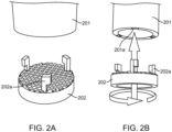
- FIGS. 2A and 2B illustrate releasably attaching a cutting blade to the tissue dissociator housing according certain embodiments.
- FIG. 2A shows cutting blade 202 before attachment to the distal end of housing 201.
- Cutting blade 202 includes fasteners 202a which are configured to fit into notches within the distal end of housing 201.
- FIG. 2B shows attaching cutting blade 202 to the distal end of housing 201 by inserting fasteners 202a into notches 201a and turning to secure the cutting blade to the distal end of the housing.
- the cutting blade includes one or more aligners for maintaining alignment with the tissue actuator.
- the cutting blade may be a planar grid and include one or more alignment holes for aligning with one or more pins positioned at the distal end of the tissue actuator.
- the cutting blade may include 1 or more alignment holes, such as 2 or more alignment holes, such as 3 or more alignment holes and including 4 or more alignment holes.
- the alignment holes for aligning the cutting bladed with the proximal end of the tissue actuator may be positioned at any convenient location along the plane of the cutting blade.
- one or more alignment holes may be positioned at the center of the cutting blade. In other embodiments, the alignment holes may be positioned along the peripheral edge of the cutting blade.
- Alignment holes in the plane of the cutting blade may have any suitable cross-sectional shape depending on the alignment pin at the distal end of the tissue actuator.
- the cross-sectional shape may include, but are not limited to rectilinear cross sectional shapes, e.g., squares, rectangles, trapezoids, triangles, hexagons, etc., curvilinear cross-sectional shapes, e.g., circles, ovals, as well as irregular shapes, e.g., a parabolic bottom portion coupled to a planar top portion.
- Each alignment hole may have the same or different cross-sectional shape, as desired.
- the cutting blade may include or is incorporated into a stripper plate.
- the stripper plate is configured to remove and retain dissociated tissue from the tines of the tissue actuator after passing the tissue through the cutting blade and retracting the tissue actuator.
- the stripper plate may be configured to retain 90% or more of the dissociated tissue passed through the cutting blade, such as 95% or more, such as 97% or more, such as 99% or more, such 99.5% or more and including 99.9% or more.
- the stripper plate is configured to remove all (i.e., 100% of the dissociated tissue that is passed through the cutting blades. In other words, when the tissue is passed through the cutting blade and the tissue actuator is retracted, the stripper plate is configured to ensure that little, if any, tissue remains on the tines of the tissue actuator.
- the stripper plate may be physically coupled to the cutting blade, such as by a fastener (e.g., hook and loop fasteners, latches, notches, grooves, pins, tethers, hinges, Velcro) or by a permanent or non-permanent adhesive or a combination thereof.
- a fastener e.g., hook and loop fasteners, latches, notches, grooves, pins, tethers, hinges, Velcro
- the cutting blade is incorporated into the stripper plate where the stripper plate is both configured to dissociate the tissue contacted when pressed through with the tissue actuator and to remove and retain the tissue from the tines of the tissue actuator.
- the cutting blade is reusable.
- reusable is meant that the cutting is capable of more than a single use where there is little to no degradation or reduction in performance by the cutting blade after each use.
- cutting blades in the subject tissue dissociators may be reused 1 more or times, such as 2 or more times, such as 3 or more times, such as 5 or more times, such as 10 or more times, such as 25 or more times, such as 50 or more times and including 100 or more times.
- cutting blades show little to no degradation or reduction in performance after each use.
- the subject cutting blades degrade by 5% or less during each use, such as by 4.5% or less, such as by 4% or less, such as by 3.5 % or less, such as by 3% or less, such as by 2.5% or less, such as by 2% or less, such as by 1.5% or less, such as by 1% or less, such as by 0.5% or less and including degrading by 0.1% or less during each use.
- the performance of the cutting blades is reduced by 5% or less after each use, such as by 4.5% or less, such as by 4% or less, such as by 3.5 % or less, such as by 3% or less, such as by 2.5% or less, such as by 2% or less, such as by 1.5% or less, such as by 1% or less, such as by 0.5% or less and including a reduction in performance by 0.1% or less after each use.
- the performance of the cutting blades is entirely unaffected by each use.
- methods may further include washing the cutting blades after use or prior to subsequent use, as described in greater detail below.
- the cutting blades may be washed by any convenient protocol, such as by washing with a solvent, using heat, electromagnetic radiation (e.g., ultraviolet light) or by ultrasound, among other washing protocols.
- the subject tissue dissociators include a tissue actuator configured to be displaced along a longitudinal axis within the housing.
- the term "displace” refers to moving the tissue actuator within the housing in a manner sufficient to bring the biological tissue sample into contact with and to press the biological tissue sample against the cutting blades to dissociate the tissue into a plurality of tissue fragments.
- the subject tissue dissociator is configured to be displaced along the longitudinal axis within the housing and can be displaced along all or part of the length of the inner chamber of the housing, such as 25% or more of the length of the housing, such as 35% or more, such as 50% or more, such as 60% or more, such as 75% or more, such as 90% or more, such as 95% or more, such as 97% or more and including 99% or more of the length of the housing.
- the tissue actuator can be displaced along the entire (i.e., 100%) length of the housing.
- the tissue actuator is configured to be displaced in a back-and-forth motion within the housing, such as moving from a distal end to a proximal end within the housing and back from the proximal end to the distal end within the housing.
- the tissue actuator is configured to be displaced in a back-and-forth motion along 25% or more of the length of the housing, such as 35% or more, such as 50% or more, such as 60% or more, such as 75% or more, such as 90% or more, such as 95% or more, such as 97% or more and including 99% or more of the length of the housing.
- the tissue actuator can be displaced in a back-and-forth motion along the entire (i.e., 100%) length of the housing.
- the cross-sectional shape of the tissue actuator may vary, depending on the shape of the inner chamber within the housing, where cross-sectional shapes of interest include, but are not limited to rectilinear cross sectional shapes, e.g., squares, rectangles, trapezoids, triangles, hexagons, etc., curvilinear cross-sectional shapes, e.g., circles, ovals, as well as irregular shapes, e.g., a parabolic bottom portion coupled to a planar top portion.
- the tissue actuator and the inner chamber of the housing have the same cross-sectional shape.
- both the tissue actuator and the inner chamber of the housing may have circular or oval cross sections or both the tissue actuator and the inner chamber of the housing may have a polygonal (e.g., octagonal) cross section.
- the tissue actuator and inner chamber within the housing have different cross-sectional shapes.
- the tissue actuator may have a curvilinear cross section and the inner chamber of the housing may have a polygonal cross section or the tissue actuator may have a polygonal cross section and the inner chamber of the housing may have a curvilinear cross section.
- the dimensions of the tissue actuator may vary where in some instances the length of tissue actuator may range from 1 cm to 50 cm, such as from 2.5 cm to 45 cm, such as from 5 cm to 40 cm, such as from 7.5 cm to 35 cm and including from 10 cm to 25 cm and the width of the tissue actuator may range from 1 cm to 50 cm, such as from 2.5 cm to 45 cm, such as from 5 cm to 40 cm, such as from 7.5 cm to 35 cm and including from 10 cm to 25 cm.
- the diameter of the of the tissue actuator may vary, in some embodiments, ranging from 1 cm to 10 cm, such as from 2 cm to 9 cm, such as from 3 cm to 8 cm and including from 4 cm to 7 cm.
- all or part of tissue actuator has a cross-section that is substantially the same size as the inner chamber of the housing.
- the outer walls of the tissue actuator are flush with the inner walls of the housing.
- 5% or more of the length of the tissue actuator may have a cross section that is substantially the same size as the inner chamber of the housing, such as 10% or more, such as 25% or more, such as 50% or more, such as 75% or more, such as 90% or more and including 95% or more of the length of the tissue actuator may have a cross section that is substantially the same size as the inner chamber of the housing.
- the entire length of the tissue actuator has a cross section that is substantially the same size as the inner chamber of the housing.
- the outer walls of the tissue actuator form a fluidic seal with the inner chamber of the housing.
- the term "fluidic seal” is used herein in its conventional sense to refer to the absence of space sufficient for fluid to flow between the outer walls of the tissue actuator and the inner chamber of the housing.
- the distal portion of the tissue actuator may form a fluidic seal with the inner chamber of the housing.
- the entire length of the tissue actuator forms a fluidic seal with the inner chamber of the housing.
- tissue is pressed into contact and through the cutting blade by the distal end of the tissue actuator.
- the distal end of the tissue actuator may be configured for contacting the biological tissue sample.
- the distal end of the actuator is flat.
- the distal end of the tissue actuator has a convex shape.
- the distal end of the tissue actuator includes one or more protrusions for contacting the biological tissue sample.
- the distal end of the tissue actuator includes one or more tines, such as two or more tines, such as 3 or more tines, such as 5 or more tines, such as 10 or more tines, such as 25 or more tines, such as 50 or more tines and including 100 or more tines.
- the tines are arranged in a grid configuration.
- Tines may have dimensions that vary, depending on the cutting blade or type of tissue being dissociated (e.g., varying by thickness, density, etc.). In some embodiments, tines may be 1 mm or greater, such as 1.5 mm or greater, such as 2 mm or greater, such as 3 mm or greater, such as 5 mm or greater, such as 10 mm or greater and including 25 mm or greater.
- the tines may have a width of 1 mm or greater, such as 2 mm or greater, such as 5 mm or greater and including 10 mm or greater.
- the distal end of the tissue actuator includes space between tines (i.e., inter-tine spacings).
- the distance between each tine may be 0.5 mm or greater, such as 1 mm or greater, such as 2 mm or greater and including 5 mm or greater.
- Tines of interest may have any suitable cross-sectional shape, depending on the shape of the cutting blade and the shape of the dissociated tissue fragments desired.
- Cross-section shapes of tines of interest include, but are not limited to rectilinear cross sectional shapes, e.g., squares, rectangles, trapezoids, triangles, hexagons, etc., curvilinear cross-sectional shapes, e.g., circles, ovals, as well as irregular shapes, e.g., a parabolic bottom portion coupled to a planar top portion.
- the outer walls of the tissue actuator include one or more aligners configured to orient the tissue actuator within the inner chamber of the housing.
- the outer walls of the tissue actuator may include an alignment protrusion, an alignment rail, an alignment notch, an alignment groove, an alignment slot or a combination thereof.
- the walls of the inner chamber of the housing may also include an aligner, such as an aligner which is complimentary to the aligner on the outer walls of the tissue actuator.
- the tissue actuator includes an alignment protrusion
- the inner chamber of the housing may include an alignment notch.
- the inner chamber of the housing may include an alignment rail.
- the size of the aligner may vary.
- the aligner may extend along all or part of the length of the tissue actuator, such as 10% or more of the length of the tissue actuator, such as 15% or more, such as 20% or more, such as 25% or more, such as 30% or more, such as 40% or more, such as 50% or more, such as 60% or more, such as 75% or more, such as 80% or more, such as 90% or more and including 95% or more.
- the aligner extends the entire length (i.e., 100%) of the tissue actuator.
- the length of the aligner may vary ranging from 0.1 cm to 25 cm, such as from 0.5 cm to 22.5 cm, such as from 1 cm to 20 cm, such as from 2.5 cm to 15 cm and including from 5 cm to 10 cm and the width of the aligner may vary ranging from 0.01 cm to 5 cm, such as from 0.05 cm to 2.5 cm, such as from 0.1 cm to 2 cm and including from 0.5 cm to 1.5 cm.
- the outer walls of the tissue actuator may include 1 or more aligners, such as 2 or more aligners, such as 3 or more aligners, such as 4 or more aligners and include 5 or more aligners.
- each aligner may be positioned anywhere on the tissue actuator as desired.
- an aligner may be positioned at a distal end, a proximal end, between the proximal end and the distal end or a combination thereof.
- Aligners may be positioned on opposite sides of the tissue actuator, such as two aligners on opposite sides at the distal end of the tissue actuator or two aligners on opposite sides at the proximal end of the tissue actuator.
- the tissue actuator includes a first aligner at the distal end and a second aligner at the proximal end.
- the distal end of the tissue actuator may include one or more aligners which couple with the cutting blade.
- the distal end of the tissue actuator may include one or more alignment pins which fit through and align the tissue actuator with the cutting blade. The dimensions of the alignment pins may vary, depending on the size of the alignment holes positioned in the cutting blade.
- the length of the alignment pins may vary ranging from 0.1 cm to 25 cm, such as from 0.5 cm to 22.5 cm, such as from 1 cm to 20 cm, such as from 2.5 cm to 15 cm and including from 5 cm to 10 cm and the width (e.g., diameter) of the alignment may vary ranging from 0.01 cm to 5 cm, such as from 0.05 cm to 2.5 cm, such as from 0.1 cm to 2 cm and including from 0.5 cm to 1.5 cm.
- each alignment pin may have one or more of the same dimensions (i.e., length and width) or each alignment pin may have different dimensions.
- each alignment pin may be the same or different lengths and may have the same or different widths.
- Alignment pins at the distal end of the tissue actuator may have any suitable cross-sectional shape depending on the alignment hole in the cutting blade.
- the cross-sectional shape may include, but are not limited to rectilinear cross sectional shapes, e.g., squares, rectangles, trapezoids, triangles, hexagons, etc., curvilinear cross-sectional shapes, e.g., circles, ovals, as well as irregular shapes, e.g., a parabolic bottom portion coupled to a planar top portion.
- Each alignment pin may have the same or different cross-sectional shape, as desired.
- the alignment pins at the distal end of the tissue actuator may be positioned at any convenient location, such as at the center of the tissue actuator or along the peripheral edge. Where more than one alignment pin is positioned along the peripheral edge of the tissue actuator distal end, the alignment pins may be spaced equidistant or at a varying distances from each other.
- the tissue actuator may be displaced along a longitudinal axis within the inner chamber of the housing. In some embodiments, the tissue actuator may be continuously displaced within the inner chamber. In other embodiments, the tissue actuator may be displaced in discrete increments. Where the tissue actuator is displaced in discrete increments, in some embodiments, the tissue actuator may include one or more notches or protrusions which provide predetermined increments for displacing the tissue actuator within the housing. For example, the tissue actuator may include 2 or more notches or protrusions, such as 3 or more notches or protrusions, such as 4 or more notches or protrusions, such as 5 or more notches or protrusions and including 10 or more notches or protrusions.
- the outer walls of the tissue actuator are threaded and configured to be screw threaded with the walls of the inner chamber of the housing. All or part of the outer walls of the tissue actuator may be threaded, such as 10% or more of the length of the tissue actuator, such as 15% or more, such as 20% or more, such as 25% or more, such as 30% or more, such as 40% or more, such as 50% or more, such as 60% or more, such as 75% or more, such as 80% or more, such as 90% or more and including 95% or more. In some embodiments, the entire length (i.e., 100%) of outer walls of the tissue actuator is threaded.
- FIG. 3 illustrates aspects of tissue actuators according to certain embodiments of the present disclosure.
- Tissue actuator 300 includes proximal end 301 and distal end 302, which is configured to contact and press a biological tissue sample through cutting blades to dissociate the biological tissue sample into a plurality of tissue fragments.
- distal end 302 of tissue actuator 300 includes an array of tines 302a which are configured to engage with the biological tissue sample. The tines may be configured to fit between the cutting blades when dissociating the biological tissue sample.
- Tissue actuator 300 also include alignment protrusion 303 configured to orient the tissue actuator within the tissue dissociator housing.
- Cap 304 is configured to connect the housing of the tissue dissociator to a container.
- the tissue actuator includes a fluid reservoir within an inner chamber of the tissue actuator.
- the fluid reservoir within the inner chamber of the tissue actuator may be any suitable shape, in some instances having the same cross-sectional shape as the tissue actuator.
- the fluid reservoir may have a rectilinear cross-sectional shape, such as a square, rectangle, trapezoid, triangle, hexagon or a curvilinear cross-sectional shape, such as a circle, oval, as well as irregular cross-sectional shapes, such as a parabolic bottom portion coupled to a planar top portion.
- the fluid reservoir may extend all or part of the length within the tissue actuator, such as 10% or more of the length within the tissue actuator, such as 15% or more, such as 20% or more, such as 25% or more, such as 30% or more, such as 40% or more, such as 50% or more, such as 60% or more, such as 75% or more, such as 80% or more, such as 90% or more and including 95% or more.
- the inner chamber extends the entire length (i.e., 100%) within the tissue actuator.
- the fluid reservoir includes more than one compartment, such as 2 or more compartments, such as 3 or more compartments, such as 4 or more compartments and including 5 or more compartments.
- Each compartment may be separated by a partition, such as a permeable, semi-permeable or impermeable barrier.
- the barrier is a partition having one or more holes such that the each compartment is in fluid communication with one or more of the other compartments.
- each compartment is separated by a semi-permeable polymeric membrane.
- the distal end of the tissue actuator is in fluid communication with the fluid reservoir, such through holes which extend from the reservoir through the distal end of the tissue actuator. Where desired, fluid from within the fluid reservoir may be expelled from the distal end of the tissue actuator by applying a positive pressure within the fluid reservoir.
- the distal end of the tissue actuator includes one or more holes which extends from the outer wall at the distal end of the tissue actuator through to the fluid reservoir, such as 2 or more holes, such as 3 or more holes, such as 5 or more holes, such as 10 or more holes, such as 25 or more holes, such as 50 or more holes and including 100 or more holes. In some instances, the holes are arranged in a grid pattern. In certain embodiments, the holes may be interspersed between tines positioned at the distal end of the tissue actuator.
- Positive pressure may be applied within the fluid reservoir to expel fluid from the distal end of the tissue actuator by any convenient protocol, such as mechanically with a plunger or hydraulically by pumping air or a gas into the fluid reservoir.
- positive pressure is applied to expel fluid through holes at the distal end of the tissue actuator with a plunger.
- the plunger is configured to be displaced along a longitudinal axis within the fluid reservoir.
- Any convenient liquid may be present in the fluid reservoir, where liquids of interest include, but are not limited to, water and other aqueous liquids, e.g., buffered solutions (such as HEPES, MOPS, PBS, etc.) and the like.
- the tissue actuator may be displaced along a longitudinal axis within the fluid reservoir continuously or in discrete increments.
- the fluid reservoir may include one or more notches or protrusions which provide predetermined increments for displacing the plunger within the fluid reservoir.
- the fluid reservoir may include 2 or more notches or protrusions, such as 3 or more notches or protrusions, such as 4 or more notches or protrusions, such as 5 or more notches or protrusions and including 10 or more notches or protrusions.
- FIG. 4 illustrates a side view of a tissue dissociator having a tissue actuator which includes a fluid reservoir according to certain embodiments.
- Tissue dissociator 400 includes housing 401 having alignment channels 401a. Positioned at the distal end of housing 401 is a cutting blade 402.
- Tissue actuator 403 fits within the inner chamber of housing 401 and includes alignment protrusions 403a which fit into alignment channels 401a to orient tissue actuator 403 for displacement along a longitudinal axis of housing 401.
- Tissue actuator 403 includes an inner chamber 403b having a fluid reservoir which is in fluid communication through holes with the distal end of the tissue actuator 403c.
- plunger 404 is inserted to apply positive pressure within the fluid reservoir to expel fluid from the distal end of tissue actuator 403c.
- the housing may be configured to be placed within container 405.
- FIG. 5 illustrates an example of a tissue actuator having a fluid reservoir within an inner chamber of the tissue actuator to certain embodiments of the present disclosure.
- Tissue actuator 502 fits within the inner chamber of tissue dissociator housing 501 and includes a proximal end 502a and a distal end 502b.
- Tissue actuator 502 includes a fluid reservoir having two compartments 502c and 502d configured to retain a fluid medium. Compartments 502c and 502d are separated by barrier 503 which includes one or more holes 503a such that compartments 502c and 502d are in fluid communication with each other.
- Tissue actuator 502 includes a plurality of holes 504 in an array configuration such that the fluid reservoir is in fluid communication with the outer wall of distal end 502b.
- tissue actuator 502 also includes plunger 505 at the proximal end to apply a positive pressure to the first compartment 502c of the fluid reservoir to expel fluid 505 through holes 504 at the distal end of tissue actuator 502.
- fluid expelled 508 through holes 504 at the distal end of tissue actuator 502 can be used to clear or wash biological tissue sample remaining in cutting blade 506.
- the entire tissue dissociator can be fit, as described above into a container 507 such as a culture tube.
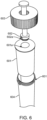
- FIGS. 6 and 7 further illustrate various aspects of tissue dissociators according certain embodiments.
- FIG. 6 is an exploded view of tissue dissociator 600 which includes housing 601 having a distal end and a proximal end, tissue actuator 602 that includes alignment protrusion 602a at the distal end of tissue actuator 602. Alignment protrusion 602a is configured to fit into alignment groove 601b which extends the entire length of the inner chamber 601a within housing 601. As illustrated in FIG. 6 , housing 601 is configured to be placed inside of container 604 and connected by screw thread with cap 603.
- FIG. 7A illustrates a top view of a tissue dissociator 700 according to certain aspects of the present disclosure.
- Tissue dissociator housing 701 includes alignment notch 701a for orienting tissue actuator 702 within the inner chamber of the housing.
- Tissue actuator 702 includes alignment protrusion 702a that fits into alignment notch 701a so that tissue actuator 702 can be displaced along a fixed longitudinal axis within the inner chamber of housing 701.
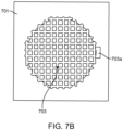
- cutting blade 703 which has a grid configuration.
- FIG. 7B shows the grid configuration of the cutting blade and includes fastener 703a for attaching the cutting blade to the distal end of tissue dissociator housing 701.
- FIG. 8 illustrates a cross-section of the tissue dissociator depicting the distal end of tissue actuator 802 engaging with cutting blade 803 in housing 801.
- tines 802a positioned at the distal end of tissue actuator 802 are arranged to fit between the cutting surfaces of cutting blade 803.
- tissue actuator 802 includes alignment protrusion 802b to orient tissue actuator 802 within the inner chamber of housing 801 so that tines 802a can slide by the cutting surfaces of cutting blade 803 without resistance.
- the tissue dissociator may include the tissue actuator, the housing and a stripper plate.
- the tines of the actuator may be circular pins of substantial length, such that prior to insertion of the actuator into the housing element or tissue mincing interface, the stripper plate is loaded onto the tine or pin array and raised all the way to the top. Long guide pins are used to maintain registration of the entire device. Using the guide pins, the actuator is then inserted into the tissue housing and the actuator is depressed all the way down. As the tissue is pressed through the holes in the tissue housing element, the stripper plate is held at the uppermost portion of the pin array. The actuator is then retracted as the stripper plate is held in place effectively stripping any residual tissue off of the pin array.
- Another feature to this embodiment includes a fluidics element such that once the tissue has been minced and a buffered solution (such as HEPES, MOPS, PBS, etc.) can be introduced under positive pressure by means of a syringe connected tube into the top-most point of the tissue housing element.
- a buffered solution such as HEPES, MOPS, PBS, etc.
- This cylinder extends down all the way through the apparatus. The terminus of the cylinder is a small protrusion on the underneath side of the housing element.
- a series of slits at the base of the cylinder produce a radial spray of fluid such that the base of the housing element is rinsed and residual tissue is or cellular debris are washed into the receptacle.
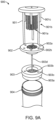
- FIG. 9A illustrates a side view of a tissue dissociator having a tissue actuator according to certain embodiments.
- Tissue dissociator 900 includes an array of pins 901a as well as three major guide pins 901b that aligns the entire device. Three minor guide pins 901c serve to align as well as provide a hard stop to dictate depth of engagement of the actuator.
- This embodiment also includes a stripper plate 902 which includes an array of holes 902a and 902b through which the actuator pins 901a pass freely as well as guide pin holes through which both sets of guide pins 901 b and 901 c pass freely.
- a tissue housing element 903 is configured with a lip 903a such that the housing element securely rests on the edge of the container 904.
- the housing element 903 also includes a tissue reservoir 903b which is where the tissue is placed.
- the tissue reservoir 903b is made up of a platform of holes through which the pin array 901a passes through freely.
- the housing element 903 also includes three holes 903c which provide alignment and through which the major guide pins 901b pass freely.
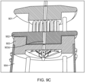
- a long hollow cylinder 903d extends up through the entire device and provides a port through which fluid may be applied under positive pressure to the underside of the housing element 903.
- FIG. 9B shows the step-wise engagement of the tissue actuator 901, the stripper plate 902, the tissue housing 903 and the container 904.
- the tissue housing is placed on the edge of the container 904.
- the stripper plate 902 is mounted onto the tissue actuator 901 and moved to the upper-most portion of the pin array as the actuator is mounted down into the housing element 903.
- the actuator 901 is pushed down into the housing element 903 until the hard stop is reached such that the pin array fully passes through the holes in the housing element 904.
- the stripper plate 902 is moved downward to its hard stop with the base of the stripper plate 902 resting against the surface of the tissue reservoir inside the housing 903.
- the stripper plate 902 is held in position, as the actuator 901 is retracted.
- FIG. 9C a detail of the fluidics component of the housing is shown.
- Methods include: 1) inserting a biological tissue into the housing of a tissue dissociator where the tissue dissociator includes a housing having a distal end and a proximal end, a cutting blade positioned at the distal end of the housing and a tissue actuator configured to be displaced along a longitudinal axis within the housing; and 2) pressing the biological tissue against the cutting blades by displacing the tissue actuator from the proximal end to the distal end of the housing in a manner sufficient to produce a dissociated biological tissue.
- the biological tissue sample may be a whole organism, plant, fungi or a subset of tissues or component parts of the organism.
- Biological tissue samples may be obtained from an in vitro source (e.g., tissue grown in laboratory culture) or from an in vivo source (e.g., a mammalian subject, a human subject, etc.).
- the tissue sample is obtained from an in vitro source.
- the tissue sample is obtained from an in vivo source, where in some instances, tissues derived from a subject are cultured, stored, or manipulated prior to evaluation.
- In vivo sources include living multi-cellular organisms and can yield non-diagnostic or diagnostic tissue samples.
- the source of the tissue sample is a "mammal” or “mammalian”, where these terms are used broadly to describe organisms which are within the class mammalia, including the orders carnivore (e.g., dogs and cats), rodentia (e.g., mice, guinea pigs, and rats), and primates (e.g., humans, chimpanzees, and monkeys). In some instances, the subjects are humans.
- Biological tissue samples may include tissue from human subjects of both genders and at any stage of development (i.e., neonates, infant, juvenile, adolescent, adult), where in certain embodiments the human subject is a juvenile, adolescent or adult.
- non-human subjects such as, but not limited to, birds, mice, rats, dogs, cats, livestock and horses.
- methods include dissociating tissue from a component part of a human subject, such as organs including but not limited to integumentary tissue (e.g. sections of the skin), oral tissue (e.g., buccal, tongue, palatal, gums), respiratory tissue (e.g., pharynx, larynx, trachea, bronchi, lungs, diaphragm) gastrointestinal tissue (e.g., esophagus, stomach, liver, gallbladder, pancreas, intestines, colon, rectum and anus.), cardiovascular tissue (e.g., heart, blood vessels), endocrine tissue (e.g., hypothalamus, pituitary gland, pineal body or pineal gland, thyroid, parathyroids, adrenal glands) and genitourinary tissue (kidneys, ureters, bladder, urethra, ovaries, fallopian tubes, uterus, vagina, mammary glands, testes,
- organs
- the size of tissue dissociated by the subject methods may vary, depending on the type and source of tissue as well as the tissue dissociator employed.
- the length of biological tissue samples may range from 1 cm to 50 cm, such as from 2.5 cm to 45 cm, such as from 5 cm to 40 cm, such as from 7.5 cm to 35 cm and including from 10 cm to 25 cm and the width of biological tissue samples may range from 1 cm to 50 cm, such as from 2.5 cm to 45 cm, such as from 5 cm to 40 cm, such as from 7.5 cm to 35 cm and including from 10 cm to 25 cm.
- the thickness of biological tissue samples may also vary, ranging from 0.001 mm to 50 mm, such as from 0.005 mm to 25 mm, such as from 0.01 mm to 15 mm, such as from 0.05 mm to 10 mm and including from 0.1 mm to 5 mm.
- methods may include dissociating biological tissue samples having a surface area ranging from 0.01 to 100 cm 2 , such as 0.05 to 50 cm 2 , such as 0.1 to 25 cm 2 , such as 0.5 to 15 cm 2 , such as 0.75 to 10 cm 2 , such as 1 to 7.5 cm 2 , and including 2 to 5 cm 2 .
- methods include dissociating biological tissue samples having a volume ranging from 0.01 to 100 cm 3 , such as 0.05 to 50 cm 3 , such as 0.1 to 25 cm 3 , such as 0.5 to 15 cm 3 , such as 0.75 to 10 cm 3 , such as 1 to 7.5 cm 3 , and including 2 to 5 cm 3 .
- a biological tissue sample is inserted into the housing of the tissue dissociator and the biologial tissue sample is displaced along a longitudinal axis within the inner chamber of the housing with a tissue actuator and contacted with cutting blades positioned at the distal end of the housing.
- the tissue actuator may be displaced along all or part of the length inner chamber of the housing to dissociate the biological tissue sample.
- the tissue actuator may be displaced along 25% or more of the length of the housing to dissociate the biological tissue sample, such as 35% or more, such as 50% or more, such as 60% or more, such as 75% or more, such as 90% or more, such as 95% or more, such as 97% or more and including 99% or more of the length of the housing.
- the tissue actuator is displaced along the entire (i.e., 100%) length of the housing to dissociate the biological tissue sample.
- the tissue actuator may be displaced continuously or in discrete increments. In some embodiments, the tissue actuator is displaced continuously. In other embodiments, the tissue actuator is displaced in one or more discrete increments, such as in 2 or more discrete increments, such as 3 or more, such as 4 or more, such as 5 or more, such as 10 or more and including in 25 or more discrete increments.
- each discrete increment may vary in length. For example, each discrete increment may be 1 mm or more, such as 2 mm or more, such as 5 mm or more, such as 10 mm or more, such as 25 mm or more and including 50 mm or more.
- tissue actuator is displaced in a back-and-forth motion along a longitudinal axis within the housing, such as moving from a distal part to a proximal part of the housing and back from the proximal part to the distal part of the housing. In some instances, tissue actuator is displaced in a back-and-forth motion along only a portion of the inner chamber of the housing.
- the tissue actuator is displaced in a back-and-forth motion along 99% or less of the length of the inner chamber of the housing, such as 95% or less, such as 90% or less, such as 85% or less, such as 80% or less, such as 75% or less, such as 70% or less, such as 65% or more, including displacing the tissue actuator in a back-and-forth motion along 50% or less of the length of the inner chamber of the housing.
- the movement of the tissue actuator may be repeated one or more times to dissociate the biological tissue sample as desired, such as 2 or more times, such as 5 or more times, such as 10 or more times, such as 15 or more times and including 25 or more times.
- the rate that the tissue actuator is displaced within the housing may vary.
- the tissue actuator may be displaced within the housing at a rate of 1 mm/ second or more, such as 2 mm/ second or more, such as 3 mm/ second or more, such as 5 mm/ second or more, such as 10 mm/ second or more and including displacing the tissue actuator within the housing at a rate of 25 mm/second or more.
- tissue dissociation can be carried out at any suitable temperature so long as the viability of the biological tissue sample and dissociated tissue fragments are preserved as desired.
- the temperature according to embodiments of the disclosure may vary, such as from -80 °C to 100 °C, such as from - 75 °C to 75 °C, such as from -50 °C to 50 °C, such as from -25 °C to 25 °C, such as from -10 °C to 10 °C, and including from 0 °C to 25 °C.
- methods also include monitoring the plurality tissue fragments produced while dissociating the biological tissue sample.
- Monitoring dissociation of the biological tissue sample may include assessing the produced plurality of tissue fragments.
- monitoring dissociation of the biological tissue sample may include evaluating the homogeneity of sizes of the produced tissue fragments.
- Monitoring dissociation of the biological tissue sample may also include evaluating the homogeneity of the shape of the produced tissue fragments. Any convenient protocol may be employed to monitor dissociation of the biological tissue sample, such as by visual inspection (either with the unaided eye or with the assistance of a computer utilizing photographic or video protocols)
- monitoring includes visually inspecting the dissociated tissue fragments in real-time. In other instances, monitoring includes assessing the dissociated tissue fragments at regular intervals, such as every 0.01 minutes, every 0.05 minutes, every 0.1 minutes, every 0.5 minutes, every 1 minute, every 5 minutes or some other interval.
- Methods of the present disclosure may also include a step of assessing the dissociated tissue fragments to identify any desired adjustments to the subject protocol.
- methods in these embodiments include providing feedback based evaluating the tissue fragments, where adjustments to the protocol may vary in terms of goal, where in some instances the desired adjustment are adjustments that ultimately result in an improved size homogeneity of shape homogeneity of the dissociated tissue fragments.
- methods may include changing one or more parts of the subject protocols. For example, one or more parameters for pressing the biological tissue sample through the cutting blade may be adjusted. In one example, methods include adjusting the rate that the biological tissue sample is pressed through the cutting blade. In some instances, the rate is increased, such as by increasing the rate of displacing the tissue actuator by 1 mm/ second or greater, such as 2 mm/ second or greater, such as by 5 mm/sec or greater, such as by 10 mm/ second or greater and by increasing the displacement rate of the tissue actuator by 25 mm/ second or greater.
- the rate is decreased, such as by decreasing the rate of displacing the tissue actuator by 1 mm/sec or greater, such as 2 mm/ second or greater, such as by 5 mm/ second or greater, such as by 10 mm/ second or greater and by decreasing the displacement rate of the tissue actuator by 25 mm/ second or greater.
- the temperature within the housing of the tissue dissociator while the biological tissue sample is pressed through the cutting blade may be adjusted.
- the temperature may be decreased, such as by 1 °C or more, such as by 2 °C or more, such as by 3 °C or more, such as by 5 °C or more, such as by 10 °C or more and including decreasing the temperature by 15 °C or more.
- the temperature is increased by 1 °C or more, such as by 2 °C or more, such as by 3 °C or more, such as by 5 °C or more, such as by 10 °C or more and including increasing the temperature by 15 °C or more.
- methods may further include washing the cutting surfaces of the cutting blade by expelling a fluid from the distal end of the tissue actuator.
- tissue actuators may include a fluid reservoir within the tissue actuator that is in fluid communication through holes at the distal end of the tissue actuator. Application of a positive pressure within the fluid reservoir, such as with a plunger, expels fluid through the holes. Fluid expelled from the tissue actuator may be employed to wash off biological tissue remaining on the distal end of the tissue actuator or for washing of tissue left behind on and between the cutting surfaces of the cutting blade.
- methods may include washing the cutting blades one or more times, such as two or more times, such as three or more times, such as five or more times and including ten or more times.
- methods may include conducting one or more additional intervals.
- protocols described herein for dissociating a biological tissue sample into a plurality of tissue fragments are repeated one or more times in a sequential manner.
- multiple interval protocols may include two or more intervals, such as three or more intervals, such as four or more intervals, such as five or more intervals, including ten or more intervals.
- kits further include kits, where kits include one or more a housings, cutting blades and tissue actuators as described herein.
- the kits can include one or more additional components (e.g., buffers, water, solvent etc.).
- the kits may further include a biological tissue sample collection device, e.g., a lance, needle or scalpel configured to a sample of integumentary tissue, oral tissue, respiratory tissue, gastrointestinal tissue, cardiovascular tissue, endocrine tissue, genitourinary tissue, muscular tissue, nervous tissue or soft skeletal tissue, as described above.
- kits may be present in separate containers, or some or all of them may be pre-combined.
- one or more components of the kit e.g., housings, cutting blades and tissue actuators, are present in a sealed pouch, e.g., a sterile foil pouch or envelope.
- the subject kits may further include (in certain embodiments) instructions for assembling the subject kit components as well as for practicing the methods for dissociating a biological tissue sample as described herein.
- These instructions may be present in the subject kits in a variety of forms, one or more of which may be present in the kit.
- One form in which these instructions may be present is as printed information on a suitable medium or substrate, e.g., a piece or pieces of paper on which the information is printed, in the packaging of the kit, in a package insert, and the like.
- a computer readable medium e.g., diskette, compact disk (CD), portable flash drive, and the like, on which the information has been recorded.
- Yet another form of these instructions that may be present is a website address which may be used via the internet to access the information at a removed site.
- the subject devices, methods, and kits find use in a variety of different applications where it is desirable to obtain biological tissue fragments having high size and shape homogeneity from a biological tissue sample.
- the present disclosure also finds use in applications where tissue fragments prepared from a biological sample may be desired for research, laboratory testing or for use in therapy.
- the subject methods and devices may facilitate the obtaining a large amount of tissue fragments to be used as a research or diagnostic specimen for diseases such as cancer.
- the subject methods and systems facilitate obtaining tissue fragments to be used in therapy, such as in the autologous treatment of wounds.
- Methods and devices of the present disclosure allow for preparing a plurality of tissue fragments from a biological tissue samples that are highly homogenous in size, shape with little waste and at a low cost.
Landscapes
- Engineering & Computer Science (AREA)
- Health & Medical Sciences (AREA)
- Life Sciences & Earth Sciences (AREA)
- Chemical & Material Sciences (AREA)
- Biochemistry (AREA)
- General Health & Medical Sciences (AREA)
- Organic Chemistry (AREA)
- Zoology (AREA)
- Wood Science & Technology (AREA)
- Bioinformatics & Cheminformatics (AREA)
- Food Science & Technology (AREA)
- Mechanical Engineering (AREA)
- Analytical Chemistry (AREA)
- Immunology (AREA)
- Pathology (AREA)
- Physics & Mathematics (AREA)
- General Physics & Mathematics (AREA)
- Biotechnology (AREA)
- Molecular Biology (AREA)
- Genetics & Genomics (AREA)
- Sustainable Development (AREA)
- General Engineering & Computer Science (AREA)
- Microbiology (AREA)
- Biomedical Technology (AREA)
- Sampling And Sample Adjustment (AREA)
- Apparatus Associated With Microorganisms And Enzymes (AREA)
- Measuring Or Testing Involving Enzymes Or Micro-Organisms (AREA)
Claims (11)
- Dissociateur de tissus (400, 600, 700, 900) comprenant :un boîtier (101, 201, 401,501, 601, 701, 801, 903) comprenant une extrémité distale ouverte (302) et une extrémité proximale ;une lame de coupe (102, 202, 402, 506, 703, 803) positionnée à l'extrémité distale ouverte (302) du boîtier (101, 201, 401, 501, 601, 701, 801, 903) ; etun actionneur de tissu (103, 300, 403, 502, 602, 702, 802, 901) comprenant un ensemble de dents et configuré pour être déplacé le long d'un axe longitudinal à l'intérieur du boîtier (101, 201, 401, 501, 601, 701, 801, 903) jusqu'à la lame de coupe à l'extrémité distale ouverte (302),dans lequel le dissociateur de tissus (400, 600, 700, 900) comprend en outre un adaptateur positionné à l'extrémité proximale (301) du boîtier (101, 201, 401, 501, 601, 701, 801, 903), dans lequel l'adaptateur est configuré pour connecter de manière libérable l'extrémité proximale (301) du boîtier (101, 201, 401, 501, 601, 701, 801, 903) à une ouverture d'un récipient (405, 507, 604, 904), dans lequel le récipient (405, 507, 604, 904) est un cylindre de seringue (104) ou un tube de centrifugeuse.
- Dissociateur de tissus (400, 600, 700, 900) selon la revendication 1, dans lequel l'actionneur de tissus (103, 300, 403, 502, 602, 702, 802, 901) comprend un réservoir de fluide.
- Dissociateur de tissus (400, 600, 700, 900) selon la revendication 2, dans lequel l'extrémité distale de l'actionneur de tissus (103, 300, 403, 502, 602, 702, 802, 901) comprend des trous en communication fluidique avec le réservoir de fluide.
- Dissociateur de tissus (400, 600, 700, 900) selon la revendication 3, dans lequel l'actionneur de tissus (103, 300, 403, 502, 602, 702, 802, 901) comprend des trous intercalés entre les dents.
- Dissociateur de tissus (400, 600, 700, 900) selon la revendication 4, dans lequel l'actionneur de tissus (103, 300, 403, 502, 602, 702, 802, 901) comprend en outre un piston configuré pour être déplacé le long d'un axe longitudinal à l'intérieur du réservoir.
- Dissociateur de tissus (400, 600, 700, 900) selon la revendication 1, dans lequel la lame de coupe (102, 202, 402, 506, 703, 803) comprend une configuration en grille.
- Dissociateur de tissus (400, 600, 700, 900) selon la revendication 6, dans lequel la lame de coupe (102, 202, 402, 506, 703, 803) est configurée pour dissocier les tissus en composants de forme identique ou de taille identique.
- Méthode de dissociation d'un tissu biologique en utilisant le dissociateur de tissu de l'une des revendications 1 à 7, comprenant les étapes suivantes :insérer un tissu biologique dans le boîtier (101, 201, 401, 501, 601, 701, 801, 903) du dissociateur de tissus de l'une des revendications 1 à 7,presser le tissu biologique contre les lames de coupe (102, 202, 402, 506, 703, 803) en déplaçant l'actionneur de tissu (103, 300, 403, 502, 702, 802) de l'extrémité proximale à l'extrémité distale (301) du boîtier (101, 201, 401, 501, 601, 701, 801, 903) d'une manière suffisante pour produire un tissu biologique dissocié comprenant des composants de forme et de taille identiques.
- La méthode selon la revendication 8, comprenant en outre la distribution d'un fluide à partir d'un réservoir qui s'étend d'une extrémité proximale (301) à une extrémité distale (302) à l'intérieur de l'actionneur de tissu (103, 300, 403, 502, 602, 702, 802, 901) à travers un ensemble de trous positionnés à l'extrémité distale (302) de l'actionneur de tissu (103, 300, 403, 502, 602, 702, 802, 901) qui sont en communication fluidique avec le réservoir.
- La méthode selon la revendication 9, dans laquelle la distribution du fluide comprend le déplacement d'un piston le long d'un axe longitudinal de l'extrémité proximale (301) à l'extrémité distale (302) à l'intérieur de l'actionneur de tissu (103, 300, 403, 502, 602, 702, 802, 901) pour expulser le fluide à travers les trous à l'extrémité distale (302).
- Un kit pour dissocier un tissu, le kit comprenant :un boîtier (101, 201, 401,501, 601, 701, 801, 903) ayant une extrémité distale ouverte (302) et une extrémité proximale (301) ;une lame de coupe positionnée à l'extrémité distale ouverte (302) du boîtier (101, 201, 401, 501, 601, 701, 801, 903) ; etun actionneur de tissu comprenant un ensemble de dents et configuré pour être déplacé le long d'un axe longitudinal à l'intérieur du boîtier (101, 201, 401, 501, 601, 701, 801, 903) jusqu'à la lame de coupe à l'extrémité distale ouverte (302),dans lequel le dissociateur de tissus (400, 600, 700, 900) comprend en outre un adaptateur positionné à l'extrémité proximale (301) du boîtier (101, 201, 401, 501, 601, 701, 801, 903), dans lequel l'adaptateur est configuré pour connecter de manière libérable l'extrémité proximale (301) du boîtier (101, 201, 401, 501, 601, 701, 801, 903) à une ouverture d'un récipient (405, 507, 604, 904), dans lequel le récipient (405, 507, 604, 904) est un cylindre de seringue (104) ou un tube de centrifugeuse.
Applications Claiming Priority (2)
| Application Number | Priority Date | Filing Date | Title |
|---|---|---|---|
| US201462046047P | 2014-09-04 | 2014-09-04 | |
| PCT/US2015/043610 WO2016036464A1 (fr) | 2014-09-04 | 2015-08-04 | Dispositifs et procédés de dissociation d'un échantillon de tissu biologique |
Publications (4)
| Publication Number | Publication Date |
|---|---|
| EP3189129A1 EP3189129A1 (fr) | 2017-07-12 |
| EP3189129A4 EP3189129A4 (fr) | 2018-04-25 |
| EP3189129C0 EP3189129C0 (fr) | 2024-02-07 |
| EP3189129B1 true EP3189129B1 (fr) | 2024-02-07 |
Family
ID=55437260
Family Applications (1)
| Application Number | Title | Priority Date | Filing Date |
|---|---|---|---|
| EP15838851.2A Active EP3189129B1 (fr) | 2014-09-04 | 2015-08-04 | Dispositifs et procédés de dissociation d'un échantillon de tissu biologique |
Country Status (6)
| Country | Link |
|---|---|
| US (1) | US10173220B2 (fr) |
| EP (1) | EP3189129B1 (fr) |
| JP (1) | JP6691107B2 (fr) |
| CN (1) | CN106604985B (fr) |
| ES (1) | ES2978108T3 (fr) |
| WO (1) | WO2016036464A1 (fr) |
Families Citing this family (27)
| Publication number | Priority date | Publication date | Assignee | Title |
|---|---|---|---|---|
| ES2759919T3 (es) | 2015-06-05 | 2020-05-12 | Douglas Scient Llc | Dispositivos para el procesamiento de muestras y métodos para su uso |
| EP3239286A1 (fr) * | 2016-04-26 | 2017-11-01 | Ludwig Boltzmann Gesellschaft | Dispositif de broyage et procédé non-enzymatique |
| CN110799826B (zh) * | 2017-06-01 | 2023-02-28 | 贝克顿·迪金森公司 | 用于解离生物组织样品的装置以及其使用方法 |
| KR102051223B1 (ko) * | 2017-09-05 | 2019-12-03 | 이준석 | 생체조직 미세화 장치 |
| CN107457053B (zh) * | 2017-09-15 | 2023-03-10 | 苏州汇科机电设备有限公司 | 易分离的重质重载辊道炉用松钵解碎机 |
| US12216032B2 (en) * | 2018-01-24 | 2025-02-04 | Fraunhofer-Gesellschaft zur Förderung der angewandten Forschung e.V. | Device and method for the dissociation of tissue |
| US12145151B2 (en) | 2018-03-03 | 2024-11-19 | Applied Cells Inc. | Methods and apparatus to separate biological entities |
| US12337319B2 (en) | 2018-03-03 | 2025-06-24 | Applied Cells Inc. | Microfluidic chip for acoustic separation of biological objects |
| US11571696B2 (en) | 2018-03-03 | 2023-02-07 | Applied Cells Inc. | Biological entity separation device and method of use |
| CN108187871B (zh) * | 2018-03-13 | 2019-08-16 | 山东卫康医学检验有限公司 | 一种rna研磨提取方法 |
| CN108435379B (zh) * | 2018-03-13 | 2020-01-24 | 吉林大学 | 一种rna研磨提取系统 |
| EP3826651A4 (fr) * | 2018-07-24 | 2022-05-11 | Healeon LLC | Dispositif et méthode pour redimensionner du tissu adipeux et d'autres tissus en vue d'une implantation |
| US12128334B2 (en) * | 2018-09-05 | 2024-10-29 | Kin Mun Chin | Filter press with threadably advanced filtrate receiving plunger |
| KR102202861B1 (ko) | 2019-04-09 | 2021-01-18 | 이준석 | 스크린 교환 장치, 이를 포함하는 생체조직 미세화 시스템, 이를 이용하는 생체조직 미세화 방법 및 이와 관련된 생체조직으로부터 타겟 물질을 분리하는 방법 |
| WO2020209609A2 (fr) * | 2019-04-09 | 2020-10-15 | 이준석 | Dispositif d'échange de tamis, système de réduction de taille de tissu biologique le comprenant, procédé de réduction de taille de tissu biologique l'utilisant, et procédé de séparation d'une substance cible à partir d'un tissu biologique pertinent |
| IT201900022350A1 (it) * | 2019-12-04 | 2021-06-04 | Hydra S R L | Dispositivo di frammentazione di tessuti in ambiente chiuso sterile con procedura asettica e suo metodo |
| CN111073809B (zh) * | 2019-12-18 | 2022-04-26 | 奥维嘉生物科技(北京)有限公司 | 一种用于无菌条件切碎生物组织的装置 |
| WO2021256986A1 (fr) * | 2020-06-15 | 2021-12-23 | Arogi Healthcare Pte. Ltd. | Homogénéisateur de tissus à entraînement direct avec capacité de séparation de débris et procédé de préparation d'un échantillon de tissus |
| US12090481B2 (en) | 2020-11-03 | 2024-09-17 | Applied Cells Inc. | Microfluidic system including cooling device |
| CN112718056B (zh) * | 2020-12-11 | 2022-04-26 | 江西省莲花山矿产实业有限公司 | 一种矿石破碎装置 |
| CN113019536B (zh) * | 2021-03-20 | 2022-05-17 | 湖南天瑞医药有限公司 | 一种药剂科用药品研磨的装置 |
| CN113350618B (zh) * | 2021-05-24 | 2022-05-31 | 中山市博爱医院 | 一种自体甲状旁腺匀浆移植器 |
| CN113333095B (zh) * | 2021-06-11 | 2022-08-12 | 内蒙古科技大学 | 一种金属冶炼用矿石破碎工艺 |
| JP7778344B2 (ja) * | 2021-09-15 | 2025-12-02 | 学校法人慈恵大学 | 生体組織処理装置 |
| US20230398145A1 (en) * | 2022-06-09 | 2023-12-14 | Ravi PONNAPPAN | Method of inducing an immune response |
| CN117305078B (zh) * | 2023-09-25 | 2024-08-27 | 成都赛恩吉诺生物科技有限公司 | 一种组织解离方法 |
| CN117305076B (zh) * | 2023-09-25 | 2024-07-19 | 成都赛恩吉诺生物科技有限公司 | 一种组织解离系统及组织解离方法 |
Citations (3)
| Publication number | Priority date | Publication date | Assignee | Title |
|---|---|---|---|---|
| US4350768A (en) * | 1980-09-19 | 1982-09-21 | Bristol Myers Company | Method for preparing single cell suspension |
| US6209439B1 (en) * | 1998-06-25 | 2001-04-03 | Petra Repac | Garlic cutter |
| EP2191750A2 (fr) * | 2008-11-03 | 2010-06-02 | Mepal B.V. | Presse pour ail |
Family Cites Families (25)
| Publication number | Priority date | Publication date | Assignee | Title |
|---|---|---|---|---|
| FR1270511A (fr) * | 1958-08-13 | 1961-09-01 | Millot Lab | Procédé et appareil de séparation de constituants endocellulaires |
| US3028314A (en) | 1960-08-31 | 1962-04-03 | Upjohn Co | Process for the continuous propagation of filamentous microorganisms |
| US3666187A (en) | 1970-05-13 | 1972-05-30 | Us Health Education & Welfare | Laboratory homogenizer |
| US3938784A (en) | 1973-08-24 | 1976-02-17 | Electronic Data Controls Corporation | Blender |
| US4828395A (en) | 1985-02-21 | 1989-05-09 | Yamato Scientific Company, Limited | Continuous flow type homogenizer |
| US5372945A (en) | 1985-06-06 | 1994-12-13 | Alchas; Paul G. | Device and method for collecting and processing fat tissue and procuring microvessel endothelial cells to produce endothelial cell product |
| US5035708A (en) | 1985-06-06 | 1991-07-30 | Thomas Jefferson University | Endothelial cell procurement and deposition kit |
| SE8801098D0 (sv) | 1988-03-24 | 1988-03-24 | Pharmacia Ab | Apparatus and method for automatic extraction of extra-chromosomal dna from a cell suspension in a container |
| US5610074A (en) | 1993-02-24 | 1997-03-11 | Beritashvili; David R. | Centrifugal method and apparatus for isolating a substance from a mixture of substances in a sample liquid |
| US5409833A (en) | 1993-07-01 | 1995-04-25 | Baxter International Inc. | Microvessel cell isolation apparatus |
| IT1260682B (it) | 1993-09-28 | 1996-04-22 | Consult T S S N C Di Roggero G | Dispositivo trituratore meccanico di materiale biologico |
| US5786207A (en) | 1997-05-28 | 1998-07-28 | University Of Pittsburgh | Tissue dissociating system and method |
| US20070166834A1 (en) * | 1998-10-05 | 2007-07-19 | Biopath Automation, L.L.C. | Apparatus and method for harvesting and handling tissue samples for biopsy analysis |
| JP4633332B2 (ja) | 2001-04-26 | 2011-02-16 | プレッシャー バイオサイエンシズ インコーポレイテッド | 試料均質化デバイスおよび生物試料の加工処理方法 |
| US20040018575A1 (en) | 2002-07-29 | 2004-01-29 | Craig Rappin | Sample preparation device and method |
| AU2002951081A0 (en) * | 2002-08-28 | 2002-09-12 | Stephen Henry Garland | Plant-material sampling and grinding system |
| JP2006505803A (ja) * | 2002-11-04 | 2006-02-16 | トランスフォーム・ファーマシューティカルズ・インコーポレイテッド | 少量の固体を取り扱う方法 |
| WO2005030936A1 (fr) | 2003-09-22 | 2005-04-07 | Battelle Memorial Institute | Dispositif de dissociation de tissu |
| IE20030856A1 (en) * | 2003-11-14 | 2005-06-15 | Enfer Technology Ltd | Sample homogeniser |
| TWI255738B (en) * | 2003-12-31 | 2006-06-01 | Ind Tech Res Inst | Tissue pulverizer |
| JP5203611B2 (ja) * | 2006-01-20 | 2013-06-05 | 株式会社ミズホメディー | 試料摩砕容器並びにそれを用いる用具及び方法 |
| WO2007083617A1 (fr) * | 2006-01-20 | 2007-07-26 | Mizuho Medy Co., Ltd. | Recipient de trituration d'echantillons, outil et procede en faisant usage |
| AU2009246306B2 (en) * | 2008-05-14 | 2014-09-25 | Biolyph, Llc | Reagent preparation and dispensing device and methods for the same |
| JP5848541B2 (ja) * | 2011-07-26 | 2016-01-27 | 日本光電工業株式会社 | 細胞単離器具 |
| KR101284708B1 (ko) * | 2011-10-26 | 2013-07-16 | 주식회사 마이크로이즈 | 생체 조직 절단 장치 |
-
2015
- 2015-08-04 CN CN201580045929.9A patent/CN106604985B/zh active Active
- 2015-08-04 WO PCT/US2015/043610 patent/WO2016036464A1/fr not_active Ceased
- 2015-08-04 US US14/817,789 patent/US10173220B2/en active Active
- 2015-08-04 JP JP2017512726A patent/JP6691107B2/ja active Active
- 2015-08-04 EP EP15838851.2A patent/EP3189129B1/fr active Active
- 2015-08-04 ES ES15838851T patent/ES2978108T3/es active Active
Patent Citations (3)
| Publication number | Priority date | Publication date | Assignee | Title |
|---|---|---|---|---|
| US4350768A (en) * | 1980-09-19 | 1982-09-21 | Bristol Myers Company | Method for preparing single cell suspension |
| US6209439B1 (en) * | 1998-06-25 | 2001-04-03 | Petra Repac | Garlic cutter |
| EP2191750A2 (fr) * | 2008-11-03 | 2010-06-02 | Mepal B.V. | Presse pour ail |
Also Published As
| Publication number | Publication date |
|---|---|
| CN106604985A (zh) | 2017-04-26 |
| EP3189129C0 (fr) | 2024-02-07 |
| JP6691107B2 (ja) | 2020-04-28 |
| WO2016036464A1 (fr) | 2016-03-10 |
| US20160069781A1 (en) | 2016-03-10 |
| EP3189129A4 (fr) | 2018-04-25 |
| CN106604985B (zh) | 2019-05-14 |
| EP3189129A1 (fr) | 2017-07-12 |
| US10173220B2 (en) | 2019-01-08 |
| ES2978108T3 (es) | 2024-09-05 |
| JP2017525382A (ja) | 2017-09-07 |
Similar Documents
| Publication | Publication Date | Title |
|---|---|---|
| US10173220B2 (en) | Devices and methods for dissociating a biological tissue sample | |
| KR100954987B1 (ko) | 조직 기재 치료를 위한 폐쇄된 자동화 시스템, 이를 이용한 투약 및 투여 방법 | |
| US10996146B2 (en) | Devices for dissociating a biological tissue sample and methods of use thereof | |
| US20130041265A1 (en) | Methods and apparatus for introducing cells at a tissue site | |
| JP2005111108A (ja) | 動物固定機器 | |
| US11707212B2 (en) | Microdialysis device comprising attachment sheet | |
| CN103860288A (zh) | 一种小鼠固定装置 | |
| IL324364A (en) | Ultrasound methods and devices for enhancing cytopathologic cell collection | |
| US20050244967A1 (en) | Closed automated system for tissue based therapy | |
| CN211723528U (zh) | 一种用于试验鼠批量均匀辐照试验固定装置 | |
| CN215227923U (zh) | 一种直接植入式开放式微灌注探针 | |
| HK1126953B (en) | Fixtures for holding micro-organs |
Legal Events
| Date | Code | Title | Description |
|---|---|---|---|
| STAA | Information on the status of an ep patent application or granted ep patent |
Free format text: STATUS: THE INTERNATIONAL PUBLICATION HAS BEEN MADE |
|
| PUAI | Public reference made under article 153(3) epc to a published international application that has entered the european phase |
Free format text: ORIGINAL CODE: 0009012 |
|
| STAA | Information on the status of an ep patent application or granted ep patent |
Free format text: STATUS: REQUEST FOR EXAMINATION WAS MADE |
|
| 17P | Request for examination filed |
Effective date: 20170404 |
|
| AK | Designated contracting states |
Kind code of ref document: A1 Designated state(s): AL AT BE BG CH CY CZ DE DK EE ES FI FR GB GR HR HU IE IS IT LI LT LU LV MC MK MT NL NO PL PT RO RS SE SI SK SM TR |
|
| AX | Request for extension of the european patent |
Extension state: BA ME |
|
| DAV | Request for validation of the european patent (deleted) | ||
| DAX | Request for extension of the european patent (deleted) | ||
| A4 | Supplementary search report drawn up and despatched |
Effective date: 20180323 |
|
| RIC1 | Information provided on ipc code assigned before grant |
Ipc: G01N 1/28 20060101AFI20180319BHEP Ipc: C12M 1/33 20060101ALI20180319BHEP |
|
| STAA | Information on the status of an ep patent application or granted ep patent |
Free format text: STATUS: EXAMINATION IS IN PROGRESS |
|
| 17Q | First examination report despatched |
Effective date: 20200415 |
|
| GRAJ | Information related to disapproval of communication of intention to grant by the applicant or resumption of examination proceedings by the epo deleted |
Free format text: ORIGINAL CODE: EPIDOSDIGR1 |
|
| GRAP | Despatch of communication of intention to grant a patent |
Free format text: ORIGINAL CODE: EPIDOSNIGR1 |
|
| GRAP | Despatch of communication of intention to grant a patent |
Free format text: ORIGINAL CODE: EPIDOSNIGR1 |
|
| STAA | Information on the status of an ep patent application or granted ep patent |
Free format text: STATUS: GRANT OF PATENT IS INTENDED |
|
| INTG | Intention to grant announced |
Effective date: 20230904 |
|
| GRAS | Grant fee paid |
Free format text: ORIGINAL CODE: EPIDOSNIGR3 |
|
| GRAA | (expected) grant |
Free format text: ORIGINAL CODE: 0009210 |
|
| STAA | Information on the status of an ep patent application or granted ep patent |
Free format text: STATUS: THE PATENT HAS BEEN GRANTED |
|
| AK | Designated contracting states |
Kind code of ref document: B1 Designated state(s): AL AT BE BG CH CY CZ DE DK EE ES FI FR GB GR HR HU IE IS IT LI LT LU LV MC MK MT NL NO PL PT RO RS SE SI SK SM TR |
|
| REG | Reference to a national code |
Ref country code: GB Ref legal event code: FG4D |
|
| REG | Reference to a national code |
Ref country code: CH Ref legal event code: EP |
|
| REG | Reference to a national code |
Ref country code: IE Ref legal event code: FG4D |
|
| REG | Reference to a national code |
Ref country code: DE Ref legal event code: R096 Ref document number: 602015087493 Country of ref document: DE |
|
| U01 | Request for unitary effect filed |
Effective date: 20240305 |
|
| U07 | Unitary effect registered |
Designated state(s): AT BE BG DE DK EE FI FR IT LT LU LV MT NL PT SE SI Effective date: 20240312 |
|
| PG25 | Lapsed in a contracting state [announced via postgrant information from national office to epo] |
Ref country code: IS Free format text: LAPSE BECAUSE OF FAILURE TO SUBMIT A TRANSLATION OF THE DESCRIPTION OR TO PAY THE FEE WITHIN THE PRESCRIBED TIME-LIMIT Effective date: 20240607 |
|
| PG25 | Lapsed in a contracting state [announced via postgrant information from national office to epo] |
Ref country code: GR Free format text: LAPSE BECAUSE OF FAILURE TO SUBMIT A TRANSLATION OF THE DESCRIPTION OR TO PAY THE FEE WITHIN THE PRESCRIBED TIME-LIMIT Effective date: 20240508 |
|
| PG25 | Lapsed in a contracting state [announced via postgrant information from national office to epo] |
Ref country code: RS Free format text: LAPSE BECAUSE OF FAILURE TO SUBMIT A TRANSLATION OF THE DESCRIPTION OR TO PAY THE FEE WITHIN THE PRESCRIBED TIME-LIMIT Effective date: 20240507 Ref country code: HR Free format text: LAPSE BECAUSE OF FAILURE TO SUBMIT A TRANSLATION OF THE DESCRIPTION OR TO PAY THE FEE WITHIN THE PRESCRIBED TIME-LIMIT Effective date: 20240207 |
|
| PG25 | Lapsed in a contracting state [announced via postgrant information from national office to epo] |
Ref country code: RS Free format text: LAPSE BECAUSE OF FAILURE TO SUBMIT A TRANSLATION OF THE DESCRIPTION OR TO PAY THE FEE WITHIN THE PRESCRIBED TIME-LIMIT Effective date: 20240507 Ref country code: NO Free format text: LAPSE BECAUSE OF FAILURE TO SUBMIT A TRANSLATION OF THE DESCRIPTION OR TO PAY THE FEE WITHIN THE PRESCRIBED TIME-LIMIT Effective date: 20240507 Ref country code: IS Free format text: LAPSE BECAUSE OF FAILURE TO SUBMIT A TRANSLATION OF THE DESCRIPTION OR TO PAY THE FEE WITHIN THE PRESCRIBED TIME-LIMIT Effective date: 20240607 Ref country code: HR Free format text: LAPSE BECAUSE OF FAILURE TO SUBMIT A TRANSLATION OF THE DESCRIPTION OR TO PAY THE FEE WITHIN THE PRESCRIBED TIME-LIMIT Effective date: 20240207 Ref country code: GR Free format text: LAPSE BECAUSE OF FAILURE TO SUBMIT A TRANSLATION OF THE DESCRIPTION OR TO PAY THE FEE WITHIN THE PRESCRIBED TIME-LIMIT Effective date: 20240508 |
|
| PG25 | Lapsed in a contracting state [announced via postgrant information from national office to epo] |
Ref country code: PL Free format text: LAPSE BECAUSE OF FAILURE TO SUBMIT A TRANSLATION OF THE DESCRIPTION OR TO PAY THE FEE WITHIN THE PRESCRIBED TIME-LIMIT Effective date: 20240207 |
|
| U20 | Renewal fee for the european patent with unitary effect paid |
Year of fee payment: 10 Effective date: 20240723 |
|
| PG25 | Lapsed in a contracting state [announced via postgrant information from national office to epo] |
Ref country code: PL Free format text: LAPSE BECAUSE OF FAILURE TO SUBMIT A TRANSLATION OF THE DESCRIPTION OR TO PAY THE FEE WITHIN THE PRESCRIBED TIME-LIMIT Effective date: 20240207 |
|
| REG | Reference to a national code |
Ref country code: ES Ref legal event code: FG2A Ref document number: 2978108 Country of ref document: ES Kind code of ref document: T3 Effective date: 20240905 |
|
| PG25 | Lapsed in a contracting state [announced via postgrant information from national office to epo] |
Ref country code: SM Free format text: LAPSE BECAUSE OF FAILURE TO SUBMIT A TRANSLATION OF THE DESCRIPTION OR TO PAY THE FEE WITHIN THE PRESCRIBED TIME-LIMIT Effective date: 20240207 |
|
| PG25 | Lapsed in a contracting state [announced via postgrant information from national office to epo] |
Ref country code: CZ Free format text: LAPSE BECAUSE OF FAILURE TO SUBMIT A TRANSLATION OF THE DESCRIPTION OR TO PAY THE FEE WITHIN THE PRESCRIBED TIME-LIMIT Effective date: 20240207 |
|
| PG25 | Lapsed in a contracting state [announced via postgrant information from national office to epo] |
Ref country code: SK Free format text: LAPSE BECAUSE OF FAILURE TO SUBMIT A TRANSLATION OF THE DESCRIPTION OR TO PAY THE FEE WITHIN THE PRESCRIBED TIME-LIMIT Effective date: 20240207 |
|
| PG25 | Lapsed in a contracting state [announced via postgrant information from national office to epo] |
Ref country code: SM Free format text: LAPSE BECAUSE OF FAILURE TO SUBMIT A TRANSLATION OF THE DESCRIPTION OR TO PAY THE FEE WITHIN THE PRESCRIBED TIME-LIMIT Effective date: 20240207 Ref country code: SK Free format text: LAPSE BECAUSE OF FAILURE TO SUBMIT A TRANSLATION OF THE DESCRIPTION OR TO PAY THE FEE WITHIN THE PRESCRIBED TIME-LIMIT Effective date: 20240207 Ref country code: RO Free format text: LAPSE BECAUSE OF FAILURE TO SUBMIT A TRANSLATION OF THE DESCRIPTION OR TO PAY THE FEE WITHIN THE PRESCRIBED TIME-LIMIT Effective date: 20240207 Ref country code: CZ Free format text: LAPSE BECAUSE OF FAILURE TO SUBMIT A TRANSLATION OF THE DESCRIPTION OR TO PAY THE FEE WITHIN THE PRESCRIBED TIME-LIMIT Effective date: 20240207 |
|
| REG | Reference to a national code |
Ref country code: DE Ref legal event code: R097 Ref document number: 602015087493 Country of ref document: DE |
|
| PLBE | No opposition filed within time limit |
Free format text: ORIGINAL CODE: 0009261 |
|
| STAA | Information on the status of an ep patent application or granted ep patent |
Free format text: STATUS: NO OPPOSITION FILED WITHIN TIME LIMIT |
|
| 26N | No opposition filed |
Effective date: 20241108 |
|
| REG | Reference to a national code |
Ref country code: CH Ref legal event code: PL |
|
| PG25 | Lapsed in a contracting state [announced via postgrant information from national office to epo] |
Ref country code: MC Free format text: LAPSE BECAUSE OF FAILURE TO SUBMIT A TRANSLATION OF THE DESCRIPTION OR TO PAY THE FEE WITHIN THE PRESCRIBED TIME-LIMIT Effective date: 20240207 Ref country code: CH Free format text: LAPSE BECAUSE OF NON-PAYMENT OF DUE FEES Effective date: 20240831 |
|
| PG25 | Lapsed in a contracting state [announced via postgrant information from national office to epo] |
Ref country code: IE Free format text: LAPSE BECAUSE OF NON-PAYMENT OF DUE FEES Effective date: 20240804 |
|
| U20 | Renewal fee for the european patent with unitary effect paid |
Year of fee payment: 11 Effective date: 20250723 |
|
| PGFP | Annual fee paid to national office [announced via postgrant information from national office to epo] |
Ref country code: ES Payment date: 20250901 Year of fee payment: 11 |
|
| PGFP | Annual fee paid to national office [announced via postgrant information from national office to epo] |
Ref country code: GB Payment date: 20250724 Year of fee payment: 11 |
|
| PG25 | Lapsed in a contracting state [announced via postgrant information from national office to epo] |
Ref country code: CY Free format text: LAPSE BECAUSE OF FAILURE TO SUBMIT A TRANSLATION OF THE DESCRIPTION OR TO PAY THE FEE WITHIN THE PRESCRIBED TIME-LIMIT; INVALID AB INITIO Effective date: 20150804 |
|
| PG25 | Lapsed in a contracting state [announced via postgrant information from national office to epo] |
Ref country code: HU Free format text: LAPSE BECAUSE OF FAILURE TO SUBMIT A TRANSLATION OF THE DESCRIPTION OR TO PAY THE FEE WITHIN THE PRESCRIBED TIME-LIMIT; INVALID AB INITIO Effective date: 20150804 |