EP3189920A1 - Dispositif de fixation, machine d'usinage par électro-érosion ou installation laser et procédé d'usinage par électro-érosion ou par laser - Google Patents
Dispositif de fixation, machine d'usinage par électro-érosion ou installation laser et procédé d'usinage par électro-érosion ou par laser Download PDFInfo
- Publication number
- EP3189920A1 EP3189920A1 EP17150898.9A EP17150898A EP3189920A1 EP 3189920 A1 EP3189920 A1 EP 3189920A1 EP 17150898 A EP17150898 A EP 17150898A EP 3189920 A1 EP3189920 A1 EP 3189920A1
- Authority
- EP
- European Patent Office
- Prior art keywords
- workpieces
- fixing device
- elements
- fixing
- wire
- Prior art date
- Legal status (The legal status is an assumption and is not a legal conclusion. Google has not performed a legal analysis and makes no representation as to the accuracy of the status listed.)
- Granted
Links
Images




Classifications
-
- B—PERFORMING OPERATIONS; TRANSPORTING
- B23—MACHINE TOOLS; METAL-WORKING NOT OTHERWISE PROVIDED FOR
- B23H—WORKING OF METAL BY THE ACTION OF A HIGH CONCENTRATION OF ELECTRIC CURRENT ON A WORKPIECE USING AN ELECTRODE WHICH TAKES THE PLACE OF A TOOL; SUCH WORKING COMBINED WITH OTHER FORMS OF WORKING OF METAL
- B23H11/00—Auxiliary apparatus or details, not otherwise provided for
- B23H11/003—Mounting of workpieces, e.g. working-tables
-
- B—PERFORMING OPERATIONS; TRANSPORTING
- B23—MACHINE TOOLS; METAL-WORKING NOT OTHERWISE PROVIDED FOR
- B23H—WORKING OF METAL BY THE ACTION OF A HIGH CONCENTRATION OF ELECTRIC CURRENT ON A WORKPIECE USING AN ELECTRODE WHICH TAKES THE PLACE OF A TOOL; SUCH WORKING COMBINED WITH OTHER FORMS OF WORKING OF METAL
- B23H1/00—Electrical discharge machining, i.e. removing metal with a series of rapidly recurring electrical discharges between an electrode and a workpiece in the presence of a fluid dielectric
-
- B—PERFORMING OPERATIONS; TRANSPORTING
- B23—MACHINE TOOLS; METAL-WORKING NOT OTHERWISE PROVIDED FOR
- B23H—WORKING OF METAL BY THE ACTION OF A HIGH CONCENTRATION OF ELECTRIC CURRENT ON A WORKPIECE USING AN ELECTRODE WHICH TAKES THE PLACE OF A TOOL; SUCH WORKING COMBINED WITH OTHER FORMS OF WORKING OF METAL
- B23H7/00—Processes or apparatus applicable to both electrical discharge machining and electrochemical machining
- B23H7/26—Apparatus for moving or positioning electrode relatively to workpiece; Mounting of electrode
- B23H7/265—Mounting of one or more thin electrodes
-
- B—PERFORMING OPERATIONS; TRANSPORTING
- B23—MACHINE TOOLS; METAL-WORKING NOT OTHERWISE PROVIDED FOR
- B23K—SOLDERING OR UNSOLDERING; WELDING; CLADDING OR PLATING BY SOLDERING OR WELDING; CUTTING BY APPLYING HEAT LOCALLY, e.g. FLAME CUTTING; WORKING BY LASER BEAM
- B23K26/00—Working by laser beam, e.g. welding, cutting or boring
- B23K26/70—Auxiliary operations or equipment
- B23K26/702—Auxiliary equipment
-
- B—PERFORMING OPERATIONS; TRANSPORTING
- B23—MACHINE TOOLS; METAL-WORKING NOT OTHERWISE PROVIDED FOR
- B23K—SOLDERING OR UNSOLDERING; WELDING; CLADDING OR PLATING BY SOLDERING OR WELDING; CUTTING BY APPLYING HEAT LOCALLY, e.g. FLAME CUTTING; WORKING BY LASER BEAM
- B23K37/00—Auxiliary devices or processes, not specially adapted for a procedure covered by only one of the other main groups of this subclass
- B23K37/04—Auxiliary devices or processes, not specially adapted for a procedure covered by only one of the other main groups of this subclass for holding or positioning work
- B23K37/0426—Fixtures for other work
- B23K37/0435—Clamps
- B23K37/0443—Jigs
-
- B—PERFORMING OPERATIONS; TRANSPORTING
- B25—HAND TOOLS; PORTABLE POWER-DRIVEN TOOLS; MANIPULATORS
- B25B—TOOLS OR BENCH DEVICES NOT OTHERWISE PROVIDED FOR, FOR FASTENING, CONNECTING, DISENGAGING, OR HOLDING
- B25B1/00—Vices
- B25B1/24—Details, e.g. jaws of special shape, slideways
- B25B1/2405—Construction of the jaws
- B25B1/241—Construction of the jaws characterised by surface features or material
-
- B—PERFORMING OPERATIONS; TRANSPORTING
- B25—HAND TOOLS; PORTABLE POWER-DRIVEN TOOLS; MANIPULATORS
- B25B—TOOLS OR BENCH DEVICES NOT OTHERWISE PROVIDED FOR, FOR FASTENING, CONNECTING, DISENGAGING, OR HOLDING
- B25B5/00—Clamps
- B25B5/06—Arrangements for positively actuating jaws
- B25B5/10—Arrangements for positively actuating jaws using screws
-
- B—PERFORMING OPERATIONS; TRANSPORTING
- B25—HAND TOOLS; PORTABLE POWER-DRIVEN TOOLS; MANIPULATORS
- B25B—TOOLS OR BENCH DEVICES NOT OTHERWISE PROVIDED FOR, FOR FASTENING, CONNECTING, DISENGAGING, OR HOLDING
- B25B5/00—Clamps
- B25B5/16—Details, e.g. jaws, jaw attachments
- B25B5/163—Jaws or jaw attachments
-
- B—PERFORMING OPERATIONS; TRANSPORTING
- B23—MACHINE TOOLS; METAL-WORKING NOT OTHERWISE PROVIDED FOR
- B23H—WORKING OF METAL BY THE ACTION OF A HIGH CONCENTRATION OF ELECTRIC CURRENT ON A WORKPIECE USING AN ELECTRODE WHICH TAKES THE PLACE OF A TOOL; SUCH WORKING COMBINED WITH OTHER FORMS OF WORKING OF METAL
- B23H7/00—Processes or apparatus applicable to both electrical discharge machining and electrochemical machining
- B23H7/02—Wire-cutting
-
- B—PERFORMING OPERATIONS; TRANSPORTING
- B23—MACHINE TOOLS; METAL-WORKING NOT OTHERWISE PROVIDED FOR
- B23K—SOLDERING OR UNSOLDERING; WELDING; CLADDING OR PLATING BY SOLDERING OR WELDING; CUTTING BY APPLYING HEAT LOCALLY, e.g. FLAME CUTTING; WORKING BY LASER BEAM
- B23K2101/00—Articles made by soldering, welding or cutting
- B23K2101/20—Tools
Definitions
- the present invention relates to a fixing device for fixing workpieces, in particular for fixing substantially rod-shaped and to be machined by means of wire erosion or lasers workpieces. Furthermore, the invention relates to a wire EDM machine or a laser system, which has a fixing device according to the invention.
- the present invention is completed by a method of wire eroding or lasing a plurality of workpieces. There are different methods for shaping or cutting workpieces in miniature format known, these methods are usually carried out so that the smallest form elements with a very high accuracy in terms of their dimensions and tolerances and positions to manufacture.
- One of these methods is wire EDM. This is a forming manufacturing process, with which electrically conductive materials can be processed with high precision on the principle of spark erosion.
- a sequence of electrical voltage pulses that generate sparks which in turn material from the workpiece, which is designed as an anode, on a continuous thin wire, which is designed here as a cathode, as well as in a separating medium, which is formed here by a dielectric , transfer.
- the high precision is achieved by the fact that the material-removing spark always jumps at the point of the smallest distance between the workpiece and the wire.
- the machining of precision parts by means of lasers is also intensified.
- the workpieces to be machined must be securely fixed in their respective machining positions. For this purpose, different devices are known.
- a clamping block which has a cuboid main body and on opposite sides arranged in parallel support prisms. These support prisms are used to hold workpieces. Furthermore, the clamping block comprises one or more clamping straps through which tensioning screws are guided in order to fix the workpieces received in the support prisms.
- a workpiece holder and a Drahtelektroerodiervorraum which provides in one embodiment, to position multiple workpieces simultaneously in a block-like recording and fix.
- the fixation of the workpieces is realized by respective, the individual workpieces associated clamping devices. Due to the simultaneous recording and fixation of several workpieces can therefore also edit several workpieces simultaneously by wire electroerodation.
- the DE 3 618 521 C1 teaches a device for clamping non-rotating workpieces, which have at least partially a polygonal cross-section.
- the device comprises a clamping body with a clamping clamp for receiving the polygonal section and a clamping means in the form of a grub screw for fixing the workpiece.
- the clamping device can also be supplemented by spring elements, which also exert pressure forces on the workpiece to be clamped.
- the EP 1 262 266 B1 teaches a clamping device for receiving and rotationally fixed fixing of threaded shanks, in particular for the purpose of electrical erosion of the respective thread.
- the workpiece is fixed at its periphery by a clamping device.
- a holding plate for a workpiece is known which makes it possible to position and fix a workpiece in a working area of a machine, in particular an electric erosion machine, by positioning and fixing the holding plate at a relatively large distance from a work table. This ensures a repeatable exact positioning of the workpiece in the work area.
- a disadvantage of the known devices for fixing the workpieces in the wire erosion process is that they usually do not allow machining of very small components due to the relatively high device tolerances.
- no micro-surgical instruments can be positioned with such high accuracy that these instruments can be manufactured with the required accuracy or the required tolerances.
- the known devices are limited in terms of flexibility with respect to the inclusion of different workpieces.
- a relatively high effort in the fixation of the workpieces or in the supply of fixed workpieces for machining process damage to the workpieces by relatively coarse adjustable fixing forces are not excluded in the known devices.
- the present invention is therefore based on the object to provide a fixing device and a wire erosion machine or a laser system and a method for wire erosion or lasers, with which an economic clamping or fixing multiple workpieces for the purpose of wire eroding or lasering of these workpieces in series production under high position accuracy of the workpieces is possible.
- This object is achieved by the fixing device according to the invention according to claim 1, by the wire EDM machine according to the invention or laser system according to claim 7 and by the inventive method for wire eroding or lasing a plurality of workpieces according to claim 8.
- Advantageous embodiments of the fixing device according to the invention are specified in the subclaims 2 to 6.
- the fixing device according to the invention is used for fixing workpieces, in particular for fixing substantially rod-shaped and to be treated by means of wire EDM or lasers workpieces.
- the fixing device comprises a support device with a plurality of mold elements for receiving and supporting a plurality of workpieces in the correspondingly shaped mold elements, and for positioning and fixing the workpieces in at least one translatory degree of freedom in the mold elements.
- the fixing device according to the invention has a clamping device with which a plurality of workpieces received in the mold elements can each be subjected to compressive force, so that the workpieces are fixed in the clamping device at least in a force-locking manner due to the pressure force application.
- the support means comprises as mold elements a plurality of through openings through which the workpieces can be guided, or the support means comprises as form elements a plurality of first channel-shaped elements in which the workpieces are receivable, whereby the workpieces in their translational degrees of freedom, which extends perpendicular to the longitudinal extension directions the workpieces or are aligned to the longitudinal extension directions of the mold elements are blocked.
- the recording and support of several workpieces in the form of elements of the support means is carried out such that the workpieces are received in the mold elements. Due to small tolerances between the form elements of the support means and the workpieces results here a fixation of the workpieces perpendicular to their longitudinal extension directions. As a result, at least one translational degree of freedom, which runs perpendicular to the longitudinal extent of the workpieces, blocked. Preferably, both perpendicular to the longitudinal extent of the respective workpiece extending translational degrees of freedom are blocked.
- the clamping device together with the form elements of the support device for the fixation of the workpiece in all degrees of freedom, namely by the generation of frictional forces between the workpieces and the clamping device by the clamping device on the Workpieces applied compressive forces are generated.
- the effort of the serial voltage or fixation of several workpieces is eliminated, which usually occurs in the previously known devices. Instead, a simultaneous tension and fixation of the workpieces is provided, so that these workpieces must be fed to the respective machining process only by movement of the fixing device.
- the feed movement of the fixing device required for this purpose can be realized via a guide device encompassed by the fixing device, in particular a linear device.
- the fixing device according to the invention is particularly suitable for fixing or positioning of rotationally symmetrical workpieces with a diameter of 0.2 to 0.4 mm.
- Such workpieces can be, for example, blanks for the production of micro-surgical instruments, as they are used in the field of ophthalmology.
- the tolerances that can be achieved by using the fixing device according to the invention are 0 to 0.1 mm in the molded elements to be produced on the workpieces.
- the fixing device according to the invention is modular, so that support means and clamping devices are each formed by a module that can be replaced in a relatively simple manner. This reduces the maintenance of the fixing device according to the invention. Due to the exact positioning and fixation of the workpieces in the fixing device also a quality control of the machined workpieces that are included in the fixing device is facilitated.
- the support means comprises as mold elements a plurality of through openings through which the workpieces can be passed, wherein the workpieces are then fixable by means of the clamping device.
- the support device has as form elements a plurality of first channel-shaped elements in or on which the workpieces can be received. In these first channel-shaped elements, therefore, the workpieces are not surrounded on all sides by the shaped elements of the support device.
- the mold elements should not exceed a dimensional tolerance of ⁇ 0.0015 mm with respect to the workpiece sections to be received by the mold elements.
- the form elements should not exceed a tolerance of ⁇ 0.0015 mm in their parallelism.
- the supporting device which is also referred to as a top plate, can be made of a stainless material and, if appropriate, hardened, wherein a wire erosion method can likewise be used for producing this support device.
- the support means on the mold elements along the longitudinal direction thereof each subsequent widening regions, wherein a respective widening region is configured such that in him an end-side portion of a guided in or on the mold workpiece in a translational degree of freedom perpendicular to the longitudinal direction of the formula is fixable.
- this expansion area should have a width which is at least twice as large as the width of the associated form element.
- This widening region may, for example, essentially have the shape of a V-profile whose deepest point or vertex or even vertex region adjoins the shaping element.
- the widening area serves for centering an end-side section which protrudes from the support device or the respective form element and which has a greater extent perpendicular to the longitudinal extension direction of the workpiece than the area of the workpiece which is positioned in the respective form element.
- the clamping device may comprise a pressure element and a counter-pressure element, between which the workpieces can be clamped.
- the clamping is realized by a pressure force realized by the pressure element in the direction of the counter-pressure element.
- the workpieces should be aligned exactly parallel. A tolerance of ⁇ 0.01 mm is acceptable.
- the receiving devices may be formed by channel-shaped elements which have a V-profile, a U-profile, a semicircular profile or a profile with a base edge and edge edges connected thereto at an angle.
- the workpieces lie with a line contact in the various channel-shaped elements. Holes for attachment of the counter-pressure element or for positioning of the counter-pressure element should not exceed a distance tolerance of ⁇ 0.005 mm to each other.
- the prismatic pressure element can be made of a stainless material and hardened, which can also be used for the production process wire EDM or lasers.
- the pressure element is also referred to as a lid and can be designed in a relatively simple embodiment as a soft surface plate, such as as a made of stainless material and hardened steel plate with hard rubber layer arranged thereon.
- This rubber layer has the advantage that despite exercising a relatively large compressive force on the workpieces they are not damaged.
- the hard rubber layer which is preferably to be firmly bonded to the steel plate, also makes it possible to compensate existing size differences of the workpieces to a certain extent.
- the pressure element can be connected by means of screws with the counter-pressure element or with the base plate, so that by pressing the screw the pressure element is moved in the direction of the counter-pressure element and thus located therebetween workpieces are clamped.
- An achievable parallelism of the pressure element to the counter-pressure element in the closed or fixed state of the clamping device should not exceed a tolerance of ⁇ 0.01 mm.
- the thickness of the hard rubber layer on the pressure element should be matched to the shape and the diameter of the workpieces to be fixed in order to apply with sufficient certainty the required compressive forces, possibly dimensional To be able to compensate for deviations of the workpieces with one another while at the same time avoiding damage to the workpieces.
- a handling area is formed between the receiving devices and the form elements of the support means, which extends parallel to the pressure force can be applied by the pressure element deeper than the position of the receiving devices.
- the positions of the receiving devices should be defined by the positions of the linear supports of the workpieces in the receiving devices in a direction along or parallel to the line of action of the compressive force caused by the pressure element.
- the position of the handling area on one side delimiting surface is deeper than the lowest point or the deepest linear extension of the receiving devices, in which case the depth is to be understood parallel to the line of action of the pressure element can be applied pressure force.
- a surface bounding the handling area is thus arranged behind the receiving devices or lower than them, so that there is a gap between the workpieces and the surface area when the workpieces are held in the fixing device. This surface can, for example, be made oblique, so that a threading process in the mold elements and / or the receiving elements is facilitated.
- the handling area serves to simplify a manually or automatically executed gripping of the workpieces in order to be able to remove them from the receiving devices, even if a workpiece should possibly become jammed in the receiving device by the pressure force applied previously.
- the support device as well as the clamping device are preferably designed as modules and fixed on a base plate. Also, this base plate can be made of a stainless material and hardened.
- the parallelism of the base plate in the areas of the terminals of the support device and the clamping device is preferably a maximum of ⁇ 0.01 mm. Positioning holes with a maximum tolerance of ⁇ 0.005 mm must also be made.
- the base plate is preferably designed to be compact in order to give the entire fixing device a low weight and Consequently, the fixing easier to make manually or automatically manageable.
- the device according to the invention can also be referred to as a chuck, with which a multiplicity of identical workpieces can be held at the time of a wire EDM or laser process and for a subsequent measurement.
- the fixing device according to the invention the workpieces can preferably be spaced parallel to one another with a maximum tolerance of ⁇ 0.002 mm. As a result, the workpieces can be stably fixed in the entire wire EDM or laser process.
- a modular construction of the fixing device allows simple and flexible exchange of individual devices, such as the support means or the clamping device to adjust the entire fixing different workpieces or different workpiece dimensions.
- a further aspect according to the invention is a wire eroding machine or laser system which has a fixing device according to the invention.
- the fixing device may be an integral part of the wire EDM machine or the laser system or else an additional unit adapted to a processing unit of the wire electric discharge machine or laser system.
- the fixing device is arranged in such a way and the machine is designed such that it can perform with a feed unit fixed in the fixing workpieces with the sufficient position accuracy of a processing area of the machine.
- the invention is supplemented by a method for wire eroding or lasering a plurality of workpieces, in particular tweezers or scissors, in which a plurality of workpieces are provided, a fixing device according to the invention is provided, the workpieces are fixed in the fixing at least non-positively and then the workpieces individually one after the other be wire eroded or lasered or, alternatively, several workpieces are simultaneously wire eroded or lasered.
- the number of each wire-eroded or lasered workpieces depends on how the wire is guided in relation to fixing device, namely simultaneously by a plurality of workpieces or in each case only by a workpiece.
- the machining of the workpieces by means of fine wire ie with a wire diameter of 0.02 mm to 0.07 mm should be done.
- Various contours such as slots, gears, etc. can be produced, whereby the dimensional tolerance of the generated eroding contour should not exceed ⁇ 0.02 mm.
- a further method aspect concerns a measurement of the workpieces or the workpiece contours or dimensions produced after the wire erosion or lasers, if the Workpieces are still received and locked in the fixing device. As a result, a quick quality control of several workpieces can be realized in a simple manner.
- the present invention is explained below with reference to the embodiments illustrated in the accompanying drawings.
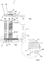
- the fixing device 1 shown here comprises a base plate 10, on which a support device 20 and a clamping device 50 for supporting or tensioning and thereby resulting fixation of a plurality of workpieces 2 are arranged.
- These workpieces 2 are designed and illustrated as elongate elements whose longitudinal extension directions 3 extend substantially perpendicular to the longitudinal extension directions of the support device 20 and the tensioning device 50.
- this may comprise a holder with which the fixing device may be mounted on a wire EDM machine or on a laser system. It can be seen that the workpieces 2 protrude from the support device 20 in the state received in the fixing device 1 with end-side sections 4.
- FIG. 3 This is especially in Figure 3 recognizable, in which the in Fig. 2 indicated detail is shown enlarged.
- the support means 20 and the clamping device 50 are connected via screw connections to the base plate 10, wherein here the SSitatisbohritch 80 can be seen and adjacent arranged pin holes 90, which serve for the introduction of pins for the purpose of exact positioning of the support means 20 and the clamping device 50 relative to each other.
- a fixing device 1 according to the invention in a second embodiment is the Figures 4-6 removable.
- a base plate 10 is provided, which may be connected to a (not shown here) holder.
- a supporting device 20 extends essentially in the plane of the base plate 10. This supporting device 20 is connected to the base plate 10 by means of screw connections.
- the base plate 10 simultaneously forms a counter-pressure element 55 of a clamping device 50.
- first embodiment of the fixing device 1 according to the invention are also in this second, in the Figures 4-6 illustrated embodiment of the fixing device according to the invention 1 form elements 21 of the support means 20 aligned with the respective receiving means 60 in the counter-pressure element 55 of the clamping device 50 is arranged and aligned.
- the workpieces 2 are positioned by the elongated form elements 21 of the support device 20 and extend into receiving means 60 of the tensioning device 50, which are formed as second channel-shaped elements 61, or in their counterpressure element 55, respectively.
- receiving means 60 of the tensioning device 50 which are formed as second channel-shaped elements 61, or in their counterpressure element 55, respectively.
- a respective clamping device 50 has a pressure element 51, also referred to as a cover, which is provided with a pressure element 51 Fig. 4 shown screw 81, of which of course several may be present, towards the counterpressure element 55 underneath can be pressed. Between them arranged workpieces 2 can be acted upon by the illustrated compressive force 52. This pressure force causes such frictional forces between the pressure element 51 and the workpieces 2 and the counter-pressure element 55 and the workpieces 2 that they are fixed in position in all degrees of freedom.
- the pressure element 51 which is also referred to as a cover, can have a steel plate 53, on the underside of which a hard rubber layer 54 is arranged, which in turn comes into contact with the workpieces 2 to be fixed.
- a handling area 70 is formed by a free space which is bounded on the one hand by the base plate 10 and this by the workpieces 2 and laterally by the support means 20 and the counter-pressure element 55.
- This handling area 70 thus extends along a direction which, viewed from the pressure element 51, leads behind the workpieces 2, parallel to the line of action of the pressure force 52.
- This handling area 70 makes it possible in a simple manner to grasp the workpieces 2 behind and thus to facilitate removal of the workpieces 2 from the clamping device when it is open.
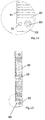
- FIGS. 7 to 16 Support devices 20 of different embodiments are shown. From the FIGS. 7 and 8 is a support means 20 can be seen, the workpieces 2 as receiving mold elements 21 first channel-shaped elements 40 which are arranged parallel to each other. In these first groove-shaped elements 40, the workpieces 2 can be inserted. As a result, the workpieces in their translational degrees of freedom 22, which is aligned perpendicular to the longitudinal extension directions 3 of the workpieces 2 and also aligned to the longitudinal extension directions 23 of the mold elements blocked. Widening regions 41, which have a greater width than the first channel-shaped elements 40 perpendicular to the longitudinal extension direction of the molded element 23, adjoin the first channel-shaped elements 40 in their longitudinal extension directions.
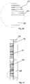
- FIG. 10 individual alternatives of the shape of the cross section of the through holes 30 are shown, wherein it is apparent that such a through hole 30 is not fixed to a round cross section, but instead also a rectangular, a polygonal or even an approximately triangular cross section, possibly with rounded corners, can have. These alternative forms of the passage openings 30 are shown only to illustrate their possible shapes and not provided in the positions shown here.
- FIGS. 11 and 12 a third embodiment of the support means 20 can be seen, wherein the support means 20 shown here also has formed as through holes 30 form elements 21.
- a fourth embodiment of the support device 20 is in the FIGS.
- FIGS. 15 and 16 A fifth embodiment of a support device 20 is in the FIGS. 15 and 16 shown, in which case the mold elements 21 of the support means 20 are in turn formed by first channel-shaped elements 40.
- Figure 17 shows a base plate 10 with arranged thereon clamping device 50, of which only the counter-pressure element 55 is shown.
- the receiving devices 60 in the form of the second channel-shaped elements 61 can be seen, which are arranged parallel to one another.
- the counter-pressure element 55 is also connected by means of screw and pins with the base plate 10, in which case only the SSitatisbohrungen 80 and the pin holes 90 can be seen.
- a detailed illustration of a counter-pressure element 55 show the FIGS. 18 to 20 , It can be seen that a respective second channel-shaped element 61 is formed on the surface of the counter-pressure plate 55.
- Such a second channel-shaped element 61 can as V-profile 61 a, as well as in FIG. 20 is shown, be formed, or as a U-profile 61 b, as a semicircular profile 61 c or as a profile with a base edge 61 d, at which the obtuse flank edges 61 e connect.
Landscapes
- Engineering & Computer Science (AREA)
- Mechanical Engineering (AREA)
- Physics & Mathematics (AREA)
- Optics & Photonics (AREA)
- Chemical & Material Sciences (AREA)
- Chemical Kinetics & Catalysis (AREA)
- Electrochemistry (AREA)
- Plasma & Fusion (AREA)
- Electrical Discharge Machining, Electrochemical Machining, And Combined Machining (AREA)
Applications Claiming Priority (1)
| Application Number | Priority Date | Filing Date | Title |
|---|---|---|---|
| DE102016100374.3A DE102016100374A1 (de) | 2016-01-11 | 2016-01-11 | Fixiervorrichtung, Drahterodiermaschine oder Laseranlage und Verfahren zum Drahterodieren bzw. Lasern |
Publications (2)
| Publication Number | Publication Date |
|---|---|
| EP3189920A1 true EP3189920A1 (fr) | 2017-07-12 |
| EP3189920B1 EP3189920B1 (fr) | 2021-03-24 |
Family
ID=57777534
Family Applications (1)
| Application Number | Title | Priority Date | Filing Date |
|---|---|---|---|
| EP17150898.9A Active EP3189920B1 (fr) | 2016-01-11 | 2017-01-10 | Dispositif de fixation, machine d'usinage par électro-érosion ou installation laser et procédé d'usinage par électro-érosion ou par laser |
Country Status (3)
| Country | Link |
|---|---|
| US (1) | US10569350B2 (fr) |
| EP (1) | EP3189920B1 (fr) |
| DE (1) | DE102016100374A1 (fr) |
Cited By (2)
| Publication number | Priority date | Publication date | Assignee | Title |
|---|---|---|---|---|
| CN108568575A (zh) * | 2018-05-02 | 2018-09-25 | 无锡臻致精工科技有限公司 | 螺帽套模加工方法和螺帽套模 |
| WO2019057455A1 (fr) * | 2017-09-20 | 2019-03-28 | Siemens Aktiengesellschaft | Orientation et fixation d'une pièce pour un usinage ultérieur au moyen d'un procédé de fabrication additive |
Families Citing this family (1)
| Publication number | Priority date | Publication date | Assignee | Title |
|---|---|---|---|---|
| US10322463B2 (en) * | 2016-05-05 | 2019-06-18 | Gm Global Technology Operations Llc. | Reconfigurable fixturing for welding |
Citations (8)
| Publication number | Priority date | Publication date | Assignee | Title |
|---|---|---|---|---|
| DE7910696U1 (de) | 1978-05-23 | 1979-07-19 | Apparate- Und Werkzeugbau Ag, Muri, Aargau (Schweiz) | Spannblock fuer werkstuecke |
| DE3618521C1 (en) | 1986-06-02 | 1987-03-12 | Erowa Ag | Device for clamping in position non-rotating workpieces |
| DE3919078C1 (fr) * | 1989-06-10 | 1990-02-01 | Erowa Ag, Reinach, Ch | |
| DE19739059A1 (de) | 1997-09-07 | 1999-03-11 | 3R Syst Int Ab | Halteplatte für ein Werkstück |
| EP1262266B1 (fr) | 2001-04-27 | 2007-07-11 | Erowa AG | Dispositif de fixation |
| CN201702591U (zh) * | 2010-05-07 | 2011-01-12 | 浙江吉利汽车有限公司 | 圆棒夹具 |
| DE112011101672T5 (de) | 2010-05-18 | 2013-04-25 | Mitsubishi Electric Corp. | Werkstückhalter, Drahtelektreoerodiervorrichtung, Dünnscheibenherstellungsverfahren und Halbleiterwafer-Herstellungsverfahren |
| CN103639771A (zh) * | 2013-11-28 | 2014-03-19 | 无锡市航鹄科技有限公司 | 一种用于加工轴类零件的工装结构 |
Family Cites Families (12)
| Publication number | Priority date | Publication date | Assignee | Title |
|---|---|---|---|---|
| US4211103A (en) * | 1978-12-08 | 1980-07-08 | American Machine & Hydraulics, Inc. | Double taper clamp |
| US5201502A (en) * | 1989-06-10 | 1993-04-13 | Erowa Ag | Apparatus for clamping workpieces which have to be machined by a machine tool |
| JP2790964B2 (ja) * | 1993-08-04 | 1998-08-27 | 本田技研工業株式会社 | 形材のスライス切断用治具装置 |
| US6125540A (en) * | 1998-02-17 | 2000-10-03 | Newcourt, Inc. | Continuous process for forming structure suitable for use as a core member |
| US7080864B2 (en) * | 2002-05-03 | 2006-07-25 | Drilltec Patents & Technologies Company, Inc. | Apparatus for shipping and storing elongated members |
| US8020843B2 (en) * | 2007-11-12 | 2011-09-20 | Hong Fu Jin Precision Industry (Shenzhen) Co., Ltd. | Clamping fixture |
| FR2988401B1 (fr) * | 2012-03-23 | 2014-04-25 | Snecma Propulsion Solide | Outillage de maintien pour traitement thermique de pieces metalliques |
| CN103084886A (zh) * | 2012-11-09 | 2013-05-08 | 无锡市航鹄科技有限公司 | 棒状工件钻孔用定位装置 |
| US9744634B2 (en) * | 2013-07-01 | 2017-08-29 | Dick PLANK | Support for workpieces |
| DE102014109611A1 (de) * | 2014-07-09 | 2016-01-14 | Walter Maschinenbau Gmbh | Magazin zur Aufbewahrung stabförmiger Werkstücke für eine Werkzeugmaschine |
| CN204277526U (zh) * | 2014-10-15 | 2015-04-22 | 富鼎电子科技(嘉善)有限公司 | 夹持装置 |
| US10300568B2 (en) * | 2015-12-31 | 2019-05-28 | Chicago Equipment Leasing Services Company | Compensating face plate vise jaws and related methods |
-
2016
- 2016-01-11 DE DE102016100374.3A patent/DE102016100374A1/de not_active Ceased
-
2017
- 2017-01-10 EP EP17150898.9A patent/EP3189920B1/fr active Active
- 2017-01-11 US US15/403,210 patent/US10569350B2/en active Active
Patent Citations (8)
| Publication number | Priority date | Publication date | Assignee | Title |
|---|---|---|---|---|
| DE7910696U1 (de) | 1978-05-23 | 1979-07-19 | Apparate- Und Werkzeugbau Ag, Muri, Aargau (Schweiz) | Spannblock fuer werkstuecke |
| DE3618521C1 (en) | 1986-06-02 | 1987-03-12 | Erowa Ag | Device for clamping in position non-rotating workpieces |
| DE3919078C1 (fr) * | 1989-06-10 | 1990-02-01 | Erowa Ag, Reinach, Ch | |
| DE19739059A1 (de) | 1997-09-07 | 1999-03-11 | 3R Syst Int Ab | Halteplatte für ein Werkstück |
| EP1262266B1 (fr) | 2001-04-27 | 2007-07-11 | Erowa AG | Dispositif de fixation |
| CN201702591U (zh) * | 2010-05-07 | 2011-01-12 | 浙江吉利汽车有限公司 | 圆棒夹具 |
| DE112011101672T5 (de) | 2010-05-18 | 2013-04-25 | Mitsubishi Electric Corp. | Werkstückhalter, Drahtelektreoerodiervorrichtung, Dünnscheibenherstellungsverfahren und Halbleiterwafer-Herstellungsverfahren |
| CN103639771A (zh) * | 2013-11-28 | 2014-03-19 | 无锡市航鹄科技有限公司 | 一种用于加工轴类零件的工装结构 |
Cited By (2)
| Publication number | Priority date | Publication date | Assignee | Title |
|---|---|---|---|---|
| WO2019057455A1 (fr) * | 2017-09-20 | 2019-03-28 | Siemens Aktiengesellschaft | Orientation et fixation d'une pièce pour un usinage ultérieur au moyen d'un procédé de fabrication additive |
| CN108568575A (zh) * | 2018-05-02 | 2018-09-25 | 无锡臻致精工科技有限公司 | 螺帽套模加工方法和螺帽套模 |
Also Published As
| Publication number | Publication date |
|---|---|
| US20170197268A1 (en) | 2017-07-13 |
| DE102016100374A1 (de) | 2017-07-13 |
| US10569350B2 (en) | 2020-02-25 |
| EP3189920B1 (fr) | 2021-03-24 |
Similar Documents
| Publication | Publication Date | Title |
|---|---|---|
| EP0255042B1 (fr) | Porte-outil pour une machine-outil, en particulier pour une machine d'électro-érosion | |
| DE19739059A1 (de) | Halteplatte für ein Werkstück | |
| EP2181792B1 (fr) | Dispositif et procédé destinés à la fabrication de forages dans l'angle d'une aube de turbine | |
| WO2011134903A1 (fr) | Ebauche d'aube de turbine ainsi que procédé et dispositif d'usinage d'une ébauche d'aube de turbine | |
| EP2903790B1 (fr) | Méthode et unité de outil pour le justage de la fente entre les parties de l'outil | |
| DE2061135A1 (de) | Praezisionssaegevorrichtung | |
| EP0593894B1 (fr) | Outil pour poinçonneuse muni d'une installation de soudage au laser | |
| EP0254741B1 (fr) | Dispositif de retenue et de manipulation d'un objet plat | |
| DE102019213013A1 (de) | ECM-Anlage mit einer Aufnahme und einer Bearbeitungsplattform | |
| EP3189920B1 (fr) | Dispositif de fixation, machine d'usinage par électro-érosion ou installation laser et procédé d'usinage par électro-érosion ou par laser | |
| DE1959852A1 (de) | Fluessigkeitszufuehrung fuer Elektroerosionsmaschinen | |
| DE3879248T2 (de) | Drahtführung für Funkenerosionsmaschine. | |
| DE3243625C2 (de) | Stanzvorrichtung zum Herstellen von Lochreihen auf dem Umfang eines Rohres | |
| DE3520540C2 (de) | Drahtführungsanordnung zur Führung einer Drahtelektrode einer Elektroerosionsmaschine | |
| EP1402985A2 (fr) | Dispositif de serrage | |
| DE102021104526B4 (de) | Werkzeug mit einem Schleifbandhalter | |
| DE10058675A1 (de) | Spannvorrichtung zum Spannen von Läuferschaufeln | |
| DE4039827A1 (de) | Vorrichtung zum einstellen des parallelen abstands zweier werkzeuge an einer numerisch gesteuerten werkzeugmaschine | |
| DE102010042778B4 (de) | Vorrichtung und Verfahren zur Herstellung eines Durchbrüche aufweisenden Blechformteils sowie Laserschneidanordnung | |
| WO2013117301A1 (fr) | Procédé et dispositif pour séparer parallèlement une pièce en plusieurs morceaux | |
| DE112022004749T5 (de) | Mehrdrahtelektroerosionsmaschine, Mehrdrahtelektroerosionsbearbeitungsverfahren, Verfahren zum Herstellen von dünnen Platten und Verfahren zum Herstellen von Halbleiterwafern | |
| DE3446306A1 (de) | Verfahren und vorrichtung zur oberflaechenbearbeitung von substratplatten fuer magnetspeicherplatten | |
| EP0202452B1 (fr) | Système de fixation et de repérage pour une machine d'électroérosion à fil | |
| EP0451305A1 (fr) | Procédé d'électroérosion | |
| DE102005004556B3 (de) | Vorrichtung und Verfahren zur Herstellung von Kantenformen, vorzugsweise Radien an Spannkanälen von Rotationszylindern |
Legal Events
| Date | Code | Title | Description |
|---|---|---|---|
| PUAI | Public reference made under article 153(3) epc to a published international application that has entered the european phase |
Free format text: ORIGINAL CODE: 0009012 |
|
| STAA | Information on the status of an ep patent application or granted ep patent |
Free format text: STATUS: THE APPLICATION HAS BEEN PUBLISHED |
|
| AK | Designated contracting states |
Kind code of ref document: A1 Designated state(s): AL AT BE BG CH CY CZ DE DK EE ES FI FR GB GR HR HU IE IS IT LI LT LU LV MC MK MT NL NO PL PT RO RS SE SI SK SM TR |
|
| AX | Request for extension of the european patent |
Extension state: BA ME |
|
| STAA | Information on the status of an ep patent application or granted ep patent |
Free format text: STATUS: REQUEST FOR EXAMINATION WAS MADE |
|
| 17P | Request for examination filed |
Effective date: 20180111 |
|
| RBV | Designated contracting states (corrected) |
Designated state(s): AL AT BE BG CH CY CZ DE DK EE ES FI FR GB GR HR HU IE IS IT LI LT LU LV MC MK MT NL NO PL PT RO RS SE SI SK SM TR |
|
| STAA | Information on the status of an ep patent application or granted ep patent |
Free format text: STATUS: EXAMINATION IS IN PROGRESS |
|
| 17Q | First examination report despatched |
Effective date: 20181210 |
|
| GRAP | Despatch of communication of intention to grant a patent |
Free format text: ORIGINAL CODE: EPIDOSNIGR1 |
|
| STAA | Information on the status of an ep patent application or granted ep patent |
Free format text: STATUS: GRANT OF PATENT IS INTENDED |
|
| INTG | Intention to grant announced |
Effective date: 20201026 |
|
| GRAS | Grant fee paid |
Free format text: ORIGINAL CODE: EPIDOSNIGR3 |
|
| GRAA | (expected) grant |
Free format text: ORIGINAL CODE: 0009210 |
|
| STAA | Information on the status of an ep patent application or granted ep patent |
Free format text: STATUS: THE PATENT HAS BEEN GRANTED |
|
| AK | Designated contracting states |
Kind code of ref document: B1 Designated state(s): AL AT BE BG CH CY CZ DE DK EE ES FI FR GB GR HR HU IE IS IT LI LT LU LV MC MK MT NL NO PL PT RO RS SE SI SK SM TR |
|
| REG | Reference to a national code |
Ref country code: GB Ref legal event code: FG4D Free format text: NOT ENGLISH |
|
| REG | Reference to a national code |
Ref country code: CH Ref legal event code: EP |
|
| REG | Reference to a national code |
Ref country code: IE Ref legal event code: FG4D Free format text: LANGUAGE OF EP DOCUMENT: GERMAN |
|
| REG | Reference to a national code |
Ref country code: AT Ref legal event code: REF Ref document number: 1373986 Country of ref document: AT Kind code of ref document: T Effective date: 20210415 Ref country code: DE Ref legal event code: R096 Ref document number: 502017009773 Country of ref document: DE |
|
| REG | Reference to a national code |
Ref country code: LT Ref legal event code: MG9D |
|
| PG25 | Lapsed in a contracting state [announced via postgrant information from national office to epo] |
Ref country code: NO Free format text: LAPSE BECAUSE OF FAILURE TO SUBMIT A TRANSLATION OF THE DESCRIPTION OR TO PAY THE FEE WITHIN THE PRESCRIBED TIME-LIMIT Effective date: 20210624 Ref country code: HR Free format text: LAPSE BECAUSE OF FAILURE TO SUBMIT A TRANSLATION OF THE DESCRIPTION OR TO PAY THE FEE WITHIN THE PRESCRIBED TIME-LIMIT Effective date: 20210324 Ref country code: GR Free format text: LAPSE BECAUSE OF FAILURE TO SUBMIT A TRANSLATION OF THE DESCRIPTION OR TO PAY THE FEE WITHIN THE PRESCRIBED TIME-LIMIT Effective date: 20210625 Ref country code: FI Free format text: LAPSE BECAUSE OF FAILURE TO SUBMIT A TRANSLATION OF THE DESCRIPTION OR TO PAY THE FEE WITHIN THE PRESCRIBED TIME-LIMIT Effective date: 20210324 Ref country code: BG Free format text: LAPSE BECAUSE OF FAILURE TO SUBMIT A TRANSLATION OF THE DESCRIPTION OR TO PAY THE FEE WITHIN THE PRESCRIBED TIME-LIMIT Effective date: 20210624 |
|
| PG25 | Lapsed in a contracting state [announced via postgrant information from national office to epo] |
Ref country code: RS Free format text: LAPSE BECAUSE OF FAILURE TO SUBMIT A TRANSLATION OF THE DESCRIPTION OR TO PAY THE FEE WITHIN THE PRESCRIBED TIME-LIMIT Effective date: 20210324 Ref country code: LV Free format text: LAPSE BECAUSE OF FAILURE TO SUBMIT A TRANSLATION OF THE DESCRIPTION OR TO PAY THE FEE WITHIN THE PRESCRIBED TIME-LIMIT Effective date: 20210324 Ref country code: SE Free format text: LAPSE BECAUSE OF FAILURE TO SUBMIT A TRANSLATION OF THE DESCRIPTION OR TO PAY THE FEE WITHIN THE PRESCRIBED TIME-LIMIT Effective date: 20210324 |
|
| REG | Reference to a national code |
Ref country code: NL Ref legal event code: MP Effective date: 20210324 |
|
| PG25 | Lapsed in a contracting state [announced via postgrant information from national office to epo] |
Ref country code: NL Free format text: LAPSE BECAUSE OF FAILURE TO SUBMIT A TRANSLATION OF THE DESCRIPTION OR TO PAY THE FEE WITHIN THE PRESCRIBED TIME-LIMIT Effective date: 20210324 |
|
| PG25 | Lapsed in a contracting state [announced via postgrant information from national office to epo] |
Ref country code: SM Free format text: LAPSE BECAUSE OF FAILURE TO SUBMIT A TRANSLATION OF THE DESCRIPTION OR TO PAY THE FEE WITHIN THE PRESCRIBED TIME-LIMIT Effective date: 20210324 Ref country code: CZ Free format text: LAPSE BECAUSE OF FAILURE TO SUBMIT A TRANSLATION OF THE DESCRIPTION OR TO PAY THE FEE WITHIN THE PRESCRIBED TIME-LIMIT Effective date: 20210324 Ref country code: EE Free format text: LAPSE BECAUSE OF FAILURE TO SUBMIT A TRANSLATION OF THE DESCRIPTION OR TO PAY THE FEE WITHIN THE PRESCRIBED TIME-LIMIT Effective date: 20210324 Ref country code: LT Free format text: LAPSE BECAUSE OF FAILURE TO SUBMIT A TRANSLATION OF THE DESCRIPTION OR TO PAY THE FEE WITHIN THE PRESCRIBED TIME-LIMIT Effective date: 20210324 |
|
| PG25 | Lapsed in a contracting state [announced via postgrant information from national office to epo] |
Ref country code: IS Free format text: LAPSE BECAUSE OF FAILURE TO SUBMIT A TRANSLATION OF THE DESCRIPTION OR TO PAY THE FEE WITHIN THE PRESCRIBED TIME-LIMIT Effective date: 20210724 Ref country code: PT Free format text: LAPSE BECAUSE OF FAILURE TO SUBMIT A TRANSLATION OF THE DESCRIPTION OR TO PAY THE FEE WITHIN THE PRESCRIBED TIME-LIMIT Effective date: 20210726 Ref country code: PL Free format text: LAPSE BECAUSE OF FAILURE TO SUBMIT A TRANSLATION OF THE DESCRIPTION OR TO PAY THE FEE WITHIN THE PRESCRIBED TIME-LIMIT Effective date: 20210324 Ref country code: RO Free format text: LAPSE BECAUSE OF FAILURE TO SUBMIT A TRANSLATION OF THE DESCRIPTION OR TO PAY THE FEE WITHIN THE PRESCRIBED TIME-LIMIT Effective date: 20210324 Ref country code: SK Free format text: LAPSE BECAUSE OF FAILURE TO SUBMIT A TRANSLATION OF THE DESCRIPTION OR TO PAY THE FEE WITHIN THE PRESCRIBED TIME-LIMIT Effective date: 20210324 |
|
| REG | Reference to a national code |
Ref country code: DE Ref legal event code: R097 Ref document number: 502017009773 Country of ref document: DE |
|
| PG25 | Lapsed in a contracting state [announced via postgrant information from national office to epo] |
Ref country code: DK Free format text: LAPSE BECAUSE OF FAILURE TO SUBMIT A TRANSLATION OF THE DESCRIPTION OR TO PAY THE FEE WITHIN THE PRESCRIBED TIME-LIMIT Effective date: 20210324 Ref country code: AL Free format text: LAPSE BECAUSE OF FAILURE TO SUBMIT A TRANSLATION OF THE DESCRIPTION OR TO PAY THE FEE WITHIN THE PRESCRIBED TIME-LIMIT Effective date: 20210324 Ref country code: ES Free format text: LAPSE BECAUSE OF FAILURE TO SUBMIT A TRANSLATION OF THE DESCRIPTION OR TO PAY THE FEE WITHIN THE PRESCRIBED TIME-LIMIT Effective date: 20210324 |
|
| PLBE | No opposition filed within time limit |
Free format text: ORIGINAL CODE: 0009261 |
|
| STAA | Information on the status of an ep patent application or granted ep patent |
Free format text: STATUS: NO OPPOSITION FILED WITHIN TIME LIMIT |
|
| PG25 | Lapsed in a contracting state [announced via postgrant information from national office to epo] |
Ref country code: SI Free format text: LAPSE BECAUSE OF FAILURE TO SUBMIT A TRANSLATION OF THE DESCRIPTION OR TO PAY THE FEE WITHIN THE PRESCRIBED TIME-LIMIT Effective date: 20210324 |
|
| 26N | No opposition filed |
Effective date: 20220104 |
|
| PG25 | Lapsed in a contracting state [announced via postgrant information from national office to epo] |
Ref country code: IS Free format text: LAPSE BECAUSE OF FAILURE TO SUBMIT A TRANSLATION OF THE DESCRIPTION OR TO PAY THE FEE WITHIN THE PRESCRIBED TIME-LIMIT Effective date: 20210724 |
|
| PG25 | Lapsed in a contracting state [announced via postgrant information from national office to epo] |
Ref country code: MC Free format text: LAPSE BECAUSE OF FAILURE TO SUBMIT A TRANSLATION OF THE DESCRIPTION OR TO PAY THE FEE WITHIN THE PRESCRIBED TIME-LIMIT Effective date: 20210324 |
|
| REG | Reference to a national code |
Ref country code: BE Ref legal event code: MM Effective date: 20220131 |
|
| PG25 | Lapsed in a contracting state [announced via postgrant information from national office to epo] |
Ref country code: LU Free format text: LAPSE BECAUSE OF NON-PAYMENT OF DUE FEES Effective date: 20220110 |
|
| PG25 | Lapsed in a contracting state [announced via postgrant information from national office to epo] |
Ref country code: BE Free format text: LAPSE BECAUSE OF NON-PAYMENT OF DUE FEES Effective date: 20220131 |
|
| PG25 | Lapsed in a contracting state [announced via postgrant information from national office to epo] |
Ref country code: IT Free format text: LAPSE BECAUSE OF FAILURE TO SUBMIT A TRANSLATION OF THE DESCRIPTION OR TO PAY THE FEE WITHIN THE PRESCRIBED TIME-LIMIT Effective date: 20210324 Ref country code: IE Free format text: LAPSE BECAUSE OF NON-PAYMENT OF DUE FEES Effective date: 20220110 |
|
| REG | Reference to a national code |
Ref country code: AT Ref legal event code: MM01 Ref document number: 1373986 Country of ref document: AT Kind code of ref document: T Effective date: 20220110 |
|
| PG25 | Lapsed in a contracting state [announced via postgrant information from national office to epo] |
Ref country code: AT Free format text: LAPSE BECAUSE OF NON-PAYMENT OF DUE FEES Effective date: 20220110 |
|
| PG25 | Lapsed in a contracting state [announced via postgrant information from national office to epo] |
Ref country code: HU Free format text: LAPSE BECAUSE OF FAILURE TO SUBMIT A TRANSLATION OF THE DESCRIPTION OR TO PAY THE FEE WITHIN THE PRESCRIBED TIME-LIMIT; INVALID AB INITIO Effective date: 20170110 |
|
| PG25 | Lapsed in a contracting state [announced via postgrant information from national office to epo] |
Ref country code: MK Free format text: LAPSE BECAUSE OF FAILURE TO SUBMIT A TRANSLATION OF THE DESCRIPTION OR TO PAY THE FEE WITHIN THE PRESCRIBED TIME-LIMIT Effective date: 20210324 Ref country code: CY Free format text: LAPSE BECAUSE OF FAILURE TO SUBMIT A TRANSLATION OF THE DESCRIPTION OR TO PAY THE FEE WITHIN THE PRESCRIBED TIME-LIMIT Effective date: 20210324 |
|
| PG25 | Lapsed in a contracting state [announced via postgrant information from national office to epo] |
Ref country code: TR Free format text: LAPSE BECAUSE OF FAILURE TO SUBMIT A TRANSLATION OF THE DESCRIPTION OR TO PAY THE FEE WITHIN THE PRESCRIBED TIME-LIMIT Effective date: 20210324 |
|
| PG25 | Lapsed in a contracting state [announced via postgrant information from national office to epo] |
Ref country code: MT Free format text: LAPSE BECAUSE OF FAILURE TO SUBMIT A TRANSLATION OF THE DESCRIPTION OR TO PAY THE FEE WITHIN THE PRESCRIBED TIME-LIMIT Effective date: 20210324 |
|
| REG | Reference to a national code |
Ref country code: CH Ref legal event code: U11 Free format text: ST27 STATUS EVENT CODE: U-0-0-U10-U11 (AS PROVIDED BY THE NATIONAL OFFICE) Effective date: 20260201 |
|
| PGFP | Annual fee paid to national office [announced via postgrant information from national office to epo] |
Ref country code: GB Payment date: 20260122 Year of fee payment: 10 |
|
| PGFP | Annual fee paid to national office [announced via postgrant information from national office to epo] |
Ref country code: DE Payment date: 20260120 Year of fee payment: 10 |
|
| PGFP | Annual fee paid to national office [announced via postgrant information from national office to epo] |
Ref country code: FR Payment date: 20260128 Year of fee payment: 10 |
|
| PGFP | Annual fee paid to national office [announced via postgrant information from national office to epo] |
Ref country code: CH Payment date: 20260201 Year of fee payment: 10 |