EP2903790B1 - Méthode et unité de outil pour le justage de la fente entre les parties de l'outil - Google Patents
Méthode et unité de outil pour le justage de la fente entre les parties de l'outil Download PDFInfo
- Publication number
- EP2903790B1 EP2903790B1 EP13779760.1A EP13779760A EP2903790B1 EP 2903790 B1 EP2903790 B1 EP 2903790B1 EP 13779760 A EP13779760 A EP 13779760A EP 2903790 B1 EP2903790 B1 EP 2903790B1
- Authority
- EP
- European Patent Office
- Prior art keywords
- tool
- punching
- cutting
- working direction
- gap
- Prior art date
- Legal status (The legal status is an assumption and is not a legal conclusion. Google has not performed a legal analysis and makes no representation as to the accuracy of the status listed.)
- Active
Links
Images


Classifications
-
- B—PERFORMING OPERATIONS; TRANSPORTING
- B26—HAND CUTTING TOOLS; CUTTING; SEVERING
- B26D—CUTTING; DETAILS COMMON TO MACHINES FOR PERFORATING, PUNCHING, CUTTING-OUT, STAMPING-OUT OR SEVERING
- B26D7/00—Details of apparatus for cutting, cutting-out, stamping-out, punching, perforating, or severing by means other than cutting
- B26D7/0006—Means for guiding the cutter
-
- B—PERFORMING OPERATIONS; TRANSPORTING
- B21—MECHANICAL METAL-WORKING WITHOUT ESSENTIALLY REMOVING MATERIAL; PUNCHING METAL
- B21D—WORKING OR PROCESSING OF SHEET METAL OR METAL TUBES, RODS OR PROFILES WITHOUT ESSENTIALLY REMOVING MATERIAL; PUNCHING METAL
- B21D28/00—Shaping by press-cutting; Perforating
- B21D28/02—Punching blanks or articles with or without obtaining scrap; Notching
- B21D28/04—Centering the work; Positioning the tools
-
- B—PERFORMING OPERATIONS; TRANSPORTING
- B26—HAND CUTTING TOOLS; CUTTING; SEVERING
- B26D—CUTTING; DETAILS COMMON TO MACHINES FOR PERFORATING, PUNCHING, CUTTING-OUT, STAMPING-OUT OR SEVERING
- B26D7/00—Details of apparatus for cutting, cutting-out, stamping-out, punching, perforating, or severing by means other than cutting
- B26D7/26—Means for mounting or adjusting the cutting member; Means for adjusting the stroke of the cutting member
- B26D7/2628—Means for adjusting the position of the cutting member
-
- B—PERFORMING OPERATIONS; TRANSPORTING
- B26—HAND CUTTING TOOLS; CUTTING; SEVERING
- B26F—PERFORATING; PUNCHING; CUTTING-OUT; STAMPING-OUT; SEVERING BY MEANS OTHER THAN CUTTING
- B26F1/00—Perforating; Punching; Cutting-out; Stamping-out; Apparatus therefor
- B26F1/38—Cutting-out; Stamping-out
- B26F1/40—Cutting-out; Stamping-out using a press, e.g. of the ram type
-
- B—PERFORMING OPERATIONS; TRANSPORTING
- B26—HAND CUTTING TOOLS; CUTTING; SEVERING
- B26F—PERFORATING; PUNCHING; CUTTING-OUT; STAMPING-OUT; SEVERING BY MEANS OTHER THAN CUTTING
- B26F1/00—Perforating; Punching; Cutting-out; Stamping-out; Apparatus therefor
- B26F1/38—Cutting-out; Stamping-out
- B26F1/44—Cutters therefor; Dies therefor
- B26F2001/4463—Methods and devices for rule setting, fixation, preparing cutting dies
Definitions
- the invention relates to a method and a tool unit for setting a punching gap for a punching or cutting machine.
- the tool unit has a first tool and a second tool. When cutting or punching the two tools are moved relative to each other. A cutting edge on the first tool and a cutting edge on the second tool work together to cut or punch a workpiece, such as a foil. There may also be a plurality of first and / or second tools.
- Such cutting or punching machines are known per se.
- DE 30 12 486 C2 a punching machine, which is for punching flat objects made of web or sheet material.
- the relative movement between the first tool and the second tool is generated there by a wedge drive.
- a transverse movement of a wedge body transversely to the working direction of the punching tool leads, for example, to the movement of a lower tool in the working direction towards the upper tool or away from it.
- the punching stroke is therefore carried out by the lower tool via a transverse movement of a wedge.
- DE 544 605 describes a device for adjusting the height of a lower blade in a cutting machine. In the working direction, the position of the cutting blade can be adjusted via one or more spindles and a wedge adjustment.
- the gap between the first and the second When first using the punching or cutting machine, the gap between the first and the second must be Tool to be adjusted. In addition, the two tools get during the operation of the punching or cutting machine at each stroke in contact with the material to be punched and worn down. This causes a punching or cutting gap between the first tool and the second tool to increase. Thus, the setting of the punching or cutting gap is necessary during initial startup and during operation. An exact gap width is of great importance especially for precision tools. If the gap is or becomes too large, the quality of the cut or punched edge on the workpiece decreases, eg a burr may form on the workpiece. Such burr formation is undesirable. For example, such a ridge when punching out foils for accumulators lead to short circuits between adjacent foils. Exceeding a maximum value of the gap width is therefore to be avoided.
- the device has an adjustment mechanism with linear guide for a carriage.
- a counter blade body is arranged, which cooperates with cutting blades on a rotor.
- the linear guide for the carriage has a relative to the rotor axis inclined linear guide axis.
- One out DE 30 12 486 C2 known punching device has a fixed head part and a relatively movable machine part, which can perform a lifting movement relative to the head part for performing the cutting or punching process.
- This lifting movement is generated in that a wedge-shaped element is present and that the movable machine part is also wedge-shaped and the two parts are in contact with each other at their wedge surfaces.
- the movable machine part can perform the required lifting movement relative to the fixed head part.
- At least the second tool is elastically deformed by means for adjusting a deformation force, thereby setting the punching or cutting gap.
- enlargement of the deformation force compensates at least partially for an enlargement of the die gap which has occurred due to wear.
- the deformation force is aligned in particular transversely to the working direction and thus transversely to the direction of movement of the first or second tool.
- the first tool can be acted upon by associated means with a deformation force to adjust the punching or cutting gap.
- the embodiments below with regard to can be explained on the second tool can also be used for the first tool.
- the deformation can be plastic or elastic.
- the tool in question when setting the gap width in the context of initial commissioning, the tool in question can also be plastically deformed.
- Such elastic or plastic deformation can be generated very easily, for example by means of clamping means, which clamp the second tool to a holding device.
- the invention eliminates a complex processing of the second tool, in particular its cutting or punching edge to adjust the punching or cutting gap to the desired size. This allows a very accurate adjustment of the gap.
- the deformation force is generated in that the second tool is pressed in a direction transverse to the working direction on the side facing away from the punching or cutting gap against a support surface and is.
- At least one tensile and / or pressure means is present in the tool unit, which prevents the second tool from moving transversely away from the support surface.
- the support surface and the co-operating tensile and / or pressure means causes a deformation of the second tool transversely to the working direction.
- the support surface is inclined at an inclination angle inclined to the working direction. This provides a simple and accurate way to vary the punching or cutting gap by elastic or plastic deformation of the second tool.
- the second tool has at least one support part which projects with a rear surface on the associated support surface the holding device for the second tool is supported.
- the rear surface extends at the same inclination angle inclined to the working direction and thus parallel to the support surface.
- the support surface and the back surface are preferably designed to be stepless and edgeless. They form, so to speak, a force transmission means which can transmit a force in the direction transverse to the working direction on the second tool in the direction of the punching or cutting gap.
- the tension and / or pressure means may be formed by anchors or screws or similar means.
- a pressure means also a stop surface may be present, against which the second tool rests on its side facing the punching or cutting gap.
- the stop surface may in particular adjacent to the punching or cutting gap, for example, arranged in extension of the punching gap next to it.
- the deformation force can also be generated by a force-generating unit which has, for example, electrical, mechanical, hydraulic or pneumatic means and can preferably be electrically controlled.
- a force-generating unit which has, for example, electrical, mechanical, hydraulic or pneumatic means and can preferably be electrically controlled.
- the force-generating unit may have a motor-spindle unit.
- a plurality of second tools may be present, which together form a die tool.
- the second tools can be at close range be arranged in particular of a few micrometers next to each other or touch without exercising a sufficiently large force for deformation force each other.
- the first tool can engage in the space between the second tools enclosed by the die cutting edge.
- the deformation force is changed in the method according to the invention in that the height of a second tool is at least partially reduced, namely at least one support part of the second tool.
- the dimension of the second tool at the position with the smallest dimension between the support surface and the cutting edge can be increased transversely to the working direction.
- the deformation force thereby increases, whereby the width of the punching or cutting gap changed and in particular reduced.
- the second tool is preferably made of steel, ceramic, carbide or other depending on the material to be punched material.
- At least one tool part having the cutting edge of the second tool is made of one of said materials and / or has a hardness that is greater than the hardness of the support part of the second tool.
- the tool part can also be designed as a separate insert, which is firmly connected to the support part.
- the area provided for changing the height of the second tool on the underside of the second tool may have a lower hardness than the cutting edge having tool part, so that a reduction in height, for example by grinding, can be done in a less hard area of the second tool.
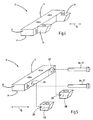
- FIG. 1 shows a punching machine 10 in a highly schematic representation.
- the punching machine 10 has a tool unit 11 according to the invention with a first tool 12 and a second tool 13. It is also set up to carry out the method according to the invention.
- the invention can also be used in cutting machines or other cutting machines.
- the two tools 12, 13 are movable in a working direction A relative to each other.
- the first tool 12 is movably guided in the working direction A on a machine frame 14 and movable via a non-illustrated dargterrorismen drive.
- the second tool 13 or both tools 12, 13 may be arranged to be movable.
- the first tool 12 forms, for example, an upper tool of the punching machine 10.
- the second tool 13 is immovably arranged in the embodiment relative to the machine frame 14 and executed according to the example as a lower tool. By a stroke of the first tool 12 relative to the second tool 13, a mold 15 is punched out of a workpiece 16.
- the workpiece 16 is formed, for example, by a plate or foil and can be supplied in the form of a band of the punching machine 10.
- the punching machine 10 can be used for punching out foils, for example lithium foils for accumulators in the desired shape 15 from the workpiece 16.
- the tool unit 11 has a plurality of second tools 13, which together form a die tool 20.
- the number and arrangement of the second tools 13 depends on the mold 15 which is to be punched out of the workpiece 16.
- Each second tool 13 has a cutting edge 21, wherein connect the cutting edges 21 of adjacent second tools 13 to one another and form a closed die cutting edge.
- a single second tool 13 may be sufficient. Accordingly, a plurality of first tools 12 may be present.
- a punching gap 23 is formed in each case.
- the punching gap 23 In order to avoid loss of quality and, for example, burr formation on the workpiece 16 or the stamped-out mold 15, the punching gap 23 must not exceed a predetermined maximum width.
- the punching gap 23 must be set exactly during initial startup of the punching machine. In the course of operation of the punching machine 10 also wear on at least a first tool 12 and / or the at least one second tool 13 occur, whereby the punching gap 23 can increase.
- a means for adjusting the punching gap 23 is provided, by means of which at least one of the second tools 13 plastically or elastically deformed and thereby a change, in particular a reduction in the width of the respective punching gap 23 can be achieved.
- all second tools 13 are deformable, but this need not necessarily be the case. In some applications, it may be sufficient to apply only a part of the second tools with a respective associated deformation force.
- the second tools 13 are releasably attached to a holding device 27.
- every second tool 13 has at least one support part 28 and, according to the example, two or three support parts 28.
- the support members 28 are in the embodiment according to the figures 3 to 7 on the punching gap 23 and the cutting edge 21 opposite side and project transversely to the working direction A of the cutting edge 21 away.
- Each support member 28 has a rear surface 29, with which it bears against an associated support surface 30 of the holding device 27.
- the rear surface 29 and the associated support surface 30 are parallel to one another and are each designed to be stepless and edgeless. Both the support surface 30, as well as the rear surface 29 extends at an inclination angle ⁇ inclined relative to the working direction A.
- the second tool 13 lies with its side facing away from the first tool 12 bottom 31 on a support surface 32 of the holding device 27.
- the underside 31 and the support surface 32 are preferably designed to be level and edged flat.
- clamping means 33 for example by screw, every second tool 13 in the working direction A is firmly clamped to the holding device 27.
- the second tool 13 is clamped with its underside 31 against the support surface 32.
- the clamping means 33 are preferably designed so that they do not absorb any force transversely to the working direction A.
- At least one tensile and / or pressure means 36 which serves to counteract a movement of the second tool 13 away from the support surface 30 and thereby generate a deformation force F together with the support surface 30, is associated with the second tool 13 to be deformed.
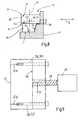
- FIG. 3 are shown schematically as screws 37 running tensile and / or pressure means 36 illustrated. These pass through the holding device 27 and are displaceable in their direction of extension relative to the holding device 27. On the holding device 27, the screws 37 are supported with a head 37 a from where they with their attached to the opposite end of the associated second tool 13 us in the embodiment via a thread 37b are screwed.
- One of the second tools 13 according to FIG. 3 has two cutting edges 21 which form a corner 34.
- Each cutting edge 21 is assigned a support surface 30 of the holding device 27 on the opposite side of the second tool 13.
- This second tool 13 can be adjusted in two directions with a deformation force F for adjusting the width B of the respective punching gap 23.
- Due to the inclination angle ⁇ of the support surface 30 can be generated by the clamping of the second tool 13 with the clamping means 33, a deformation force F on the second tool 13.
- the back surface 29 reaches when clamping in contact with the support surface 30 before the bottom 31 of the second tool on the support surface 32 has reached its end position. Because of the screws 37, however, the second tool can not move away from the inclined support surface 30 during clamping, whereby a deformation force F is generated transversely to the working direction A.
- the deformation force F is sufficiently large in order to deform the second tool 13 transversely to the working direction A in the direction of the gap width of the associated punching gap 23.
- the position of the cutting edge 21 of the respective second tool 13 with respect to the cutting edge 22 of the associated first tool 12 can be changed and thus the width of the punching gap 23 can be adjusted. It is therefore possible, if necessary, to adjust the gap width of the die gap 23 during assembly, initial startup or during ongoing operation. For example, the gap width B can be reduced if it had increased due to wear.
- the inventively effected position changes of the cutting edge 21 of the second tool 13 on the deformation thereof are small and are in the range of 1 to 2 micrometers. However, this displacement of the cutting edge 21 is sufficient to readjust the punching gap 23, which usually has a width of 1 to 3 or 4 microns, in order to obtain a qualitatively perfect and in particular quasi-burr-free punching edge on the mold 15.
- the second tool 13 may be arranged on its side facing away from the support surface 30 a stop surface or other suitable pressure means, so that the second tool 13 between the stop surface and the pressure means and the support surface 30 via a deformation force is deformed.
- the height of the second tool 13 in the working direction A can be reduced from a first height H1 to a second height H2 ( FIGS. 6 and 7 ).
- a layer on the underside 31 of the second tool 13 can be removed, which in FIG. 6 is shown schematically dotted. Since the distance of the support surface 30 relative to the first tool 12 measured measured transversely to the working direction A and smaller towards the support surface 32, so to speak, increases the effective dimension of the second tool 13 transverse to the working direction A in the direction of the width of the cutting gap 23.
- the deformation force F between the support surface 30 and the stop surface 32 increases, whereby the elastic deformation of the relevant second tool 13 and the adjacent, the stop surface 32 having second tool 13 changes.
- the position of the cutting edge 21 with respect to the cutting edge 22 of the first tool 12 can be changed and the width B of the punching gap 23 can be reduced by a difference value D ( FIG. 7 ).
- the second tool 13 and preferably all second tools 13 are made of steel, ceramic, carbide or other suitable materials ( FIG. 4 ). It is also possible to produce or particularly to harden only a region having the cutting edge 21, which can be designated as a tool part 35, made of hard metal. The hardness of the tool part 35 may be greater than the hardness of the remaining part of the second tool 13, in particular of the support parts 28.
- the tool part 35 may also be designed as a separate insert, which is connected to the support members 28.
- the compound can be made soluble or insoluble.
- the area with the underside 31 of the second tool 13 may have a lower hardness than the area that has the cutting edge 21. As a result, the lower side 31 of the second tool 13 can be better processed to reduce the height.
- FIG. 8 shows a modified embodiment of a second tool.
- the support member 28 is not as described above on the cutting edge 21 opposite side, but provided on the bottom 31 of the second tool 13.
- the rear surface 29 present on the support part 28 is assigned to a support surface 30 as described above.
- the base 38 of the support parts 28 adjoining the rear surface 29 is machined, as shown in FIG FIGS. 6 and 7 for the bottom 31 is described.
- the base 38 is associated with the support surface 32 on the holding device 27. Otherwise, the mode of operation and construction correspond to the previously described embodiments, so that reference is made to the above description.
- a modified second tool 13 is shown. It has, for example, a substantially cuboid contour.
- the rear surface 29 and the abutting support surface 29 of the holding device 27 are not inclined with respect to the working direction A.
- This is connected to a force-generating unit 40, which may have, for example, an electric motor or hydraulic or pneumatic means for generating power.
- the tension and / or pressure means 36 may be, for example, a driven by an electric motor spindle, which is connected to the second tool 13.
- the force generating unit 40 to adjust the width B of the punching gap 23, the deformation force F set.
- a manual adjusting means may be present.
- the screws 37 can be used as tension and / or pressure means 36 and the deformation force F can be adjusted manually via the screws 37.
- the width B of the punching gap of the associated second tool 13 can also be regulated.
- the width B can be measured via a particularly optical measuring device and in one Control unit are compared with a setpoint. In case of deviations, the control unit activates the force-generating unit 40 to increase or decrease the deformation force F.
- FIGS. 8 and 9 a separate insert may be provided as a tool part 35.
- Supporting parts 28 may also be present both on the underside 31 and on the side of the second tool 13 opposite the cutting edge 21 (FIG. FIGS. 3 to 7 and 8th ).
- the deformation force F it is possible to set the deformation force F at different locations of a second tool 13 of different sizes. This is done, for example, to adapt the width B punching gap 23 to a non-straight course of the associated edge of a first tool 12.
- the second tool 13 for example, a plurality of tensile and / or pressure means 36 associated by means of which in each case a desired amount for a local deformation force F is adjustable.
- the invention relates to a tool unit 11 and a method for changing the width B of a punching gap 23 between a first tool 12 and a second tool 13 of the tool unit 11.
- a plurality of second tools 13 are provided, which together form a die tool 20 with a circumferential die cutting edge, in which the first tool 12 can engage with its cutting edge 22.
- a punching gap 23 is formed in each case with a width B between the cutting edges 21, 22nd measured transversely to a working direction A.
- the first tool 12 and the second tool 13 are moved relative to each other.
- About clamping means 33 can act on a second tool 13 acting deformation force transverse to the direction A, whereby the position of the respective cutting edge 21 and thus the width B of the punching gap 23 change and set.
Landscapes
- Engineering & Computer Science (AREA)
- Mechanical Engineering (AREA)
- Life Sciences & Earth Sciences (AREA)
- Forests & Forestry (AREA)
- Perforating, Stamping-Out Or Severing By Means Other Than Cutting (AREA)
Claims (11)
- Procédé d'ajustage d'un jeu de poinçonnage ou de découpage (23) sur une unité d'outil (11) d'une machine à poinçonner ou à découper (10), l'unité d'outil (11) présentant un premier outil (12) et au moins un deuxième outil (13), qui sont déplacés l'un par rapport à l'autre dans une direction de travail (A) en vue du poinçonnage ou du découpage, le jeu de poinçonnage ou de découpage (23) existant transversalement à la direction de travail (A) entre le premier outil (12) et le deuxième outil (13),
le deuxième outil (13) présentant au moins un élément d'appui (28) qui est en appui avec une face arrière (29) sur une surface d'appui (30) d'un dispositif de support (27) pour le deuxième outil (13),
la hauteur (H1, H2) de l'élément d'appui (28) du deuxième outil (13) étant diminuée dans la direction de travail (A), en vue d' l'ajustement du jeu de poinçonnage ou de découpage (23),
et l'ajustement du jeu de poinçonnage ou de découpage (23) s'effectuant par déformation du deuxième outil (13). - Procédé selon la revendication 1, caractérisé en ce qu'une force de déformation (F) agit sur le deuxième outil (13), transversalement à la direction de travail (A).
- Procédé selon la revendication 1 ou 2, caractérisé en ce que la force de déformation (F) est produite par l'intermédiaire d'une unité de production de force (40) qui présente des moyens électriques et/ou hydrauliques et/ou pneumatiques pour la production de la force de déformation (F).
- Procédé selon l'une des revendications précédentes, caractérisé en ce que la surface d'appui (30) est orientée en biais sous un angle d'inclinaison (α) par rapport à la direction de travail (A)
- Procédé selon l'une des revendications précédentes, caractérisé en ce que le deuxième outil (13), sur sa face tournée vers le jeu de poinçonnage ou de découpage (23), est en appui sur une surface de butée.
- Procédé selon la revendication 5, caractérisé en ce que la déformation du deuxième outil (13) est obtenue par serrage du deuxième outil (13) entre la surface de butée et la surface d'appui (30).
- Unité d'outil (11) pour une machine à poinçonner ou à découper (10),
comprenant un premier outil (12) et un deuxième outil (13), le premier outil (12) et le deuxième outil (13) pouvant être déplacés l'un par rapport à l'autre dans une direction de travail (A) en vue du poinçonnage ou du découpage,
comprenant un jeu de poinçonnage ou de découpage (23), transversalement à la direction de travail (A), entre le premier outil (12) et le deuxième outil (13),
le deuxième outil (13) présentant un élément d'appui (28) et étant en appui, par l'intermédiaire d'un élément d'appui (28), sur le côté éloigné du jeu de poinçonnage ou de découpage (23), dans une direction transversale à la direction de travail (A), sachant qu'est associé au deuxième outil (13), au moins un moyen de traction et/ou de pression qui agit à l'encontre d'un mouvement du deuxième outil (13), dans le sens opposé à la surface d'appui (30). - Unité d'outil selon la revendication 7, caractérisé en ce que la surface d'appui (30) s'étend en biais par rapport à la direction de travail (A).
- Unité d'outil selon la revendication 7 ou 8, caractérisé en ce qu'il y a plusieurs deuxièmes outils (13) qui forment ensemble un outil à matrice (20).
- Unité d'outil selon la revendication 9, caractérisé en ce qu'au moins une partie des deuxièmes outils (13) peut être sollicitée avec une force de déformation (F).
- Unité d'outil selon l'une des revendications 7 à 10, caractérisé en ce que l'arête de coupe (21) du deuxième outil (13) est présente sur une partie d'outil (35) dont la dureté est supérieure à la dureté de l'élément d'appui (28).
Applications Claiming Priority (2)
| Application Number | Priority Date | Filing Date | Title |
|---|---|---|---|
| DE102012109434.9A DE102012109434A1 (de) | 2012-10-04 | 2012-10-04 | Verfahren und Werkzeugeinheit zur Einstellung eines Stanzspalts |
| PCT/EP2013/070729 WO2014053643A1 (fr) | 2012-10-04 | 2013-10-04 | Procédé et unité d'outil pour ajuster une fente de découpe |
Publications (2)
| Publication Number | Publication Date |
|---|---|
| EP2903790A1 EP2903790A1 (fr) | 2015-08-12 |
| EP2903790B1 true EP2903790B1 (fr) | 2016-09-14 |
Family
ID=49448111
Family Applications (1)
| Application Number | Title | Priority Date | Filing Date |
|---|---|---|---|
| EP13779760.1A Active EP2903790B1 (fr) | 2012-10-04 | 2013-10-04 | Méthode et unité de outil pour le justage de la fente entre les parties de l'outil |
Country Status (9)
| Country | Link |
|---|---|
| US (1) | US9796103B2 (fr) |
| EP (1) | EP2903790B1 (fr) |
| JP (1) | JP6243915B2 (fr) |
| KR (1) | KR102193253B1 (fr) |
| CN (1) | CN105102192B (fr) |
| DE (1) | DE102012109434A1 (fr) |
| HU (1) | HUE031310T2 (fr) |
| PL (1) | PL2903790T3 (fr) |
| WO (1) | WO2014053643A1 (fr) |
Families Citing this family (10)
| Publication number | Priority date | Publication date | Assignee | Title |
|---|---|---|---|---|
| EP3246140B1 (fr) * | 2016-05-16 | 2019-06-26 | Tetra Laval Holdings & Finance S.A. | Unité de coupe et procédé de coupe |
| KR102341464B1 (ko) * | 2018-05-04 | 2021-12-22 | 주식회사 엘지에너지솔루션 | 전극시트 커팅장치 및 커팅방법 |
| CN108746317A (zh) * | 2018-05-30 | 2018-11-06 | 大连理工大学 | 一种可连续调整间隙的冲裁装置 |
| KR101939706B1 (ko) * | 2018-06-28 | 2019-01-18 | 주식회사 지에스피컴퍼니 | 필름커팅장치 및 필름커팅장치 코팅층 형성방법 |
| DE102018122717A1 (de) * | 2018-09-17 | 2020-03-19 | Trumpf Werkzeugmaschinen Gmbh + Co. Kg | Verfahren zur schneidenden Bearbeitung von Rohren in einer Laserrohrschneidmaschine sowie Laserrohrschneidmaschine |
| CN112091056B (zh) * | 2020-08-24 | 2023-01-10 | 珠海格力精密模具有限公司 | 一种冲切方法 |
| CN113523091B (zh) * | 2021-06-23 | 2022-07-19 | 东风柳州汽车有限公司 | 一种7字形孔加工方法 |
| US12427689B2 (en) * | 2021-08-11 | 2025-09-30 | Fabri-Kal Llc | Trim tool with adjustable trim centers |
| CN114101784A (zh) * | 2021-12-21 | 2022-03-01 | 新疆八一钢铁股份有限公司 | 一种阶梯式剪刃弹扁定尺剪切方法 |
| CN116984474B (zh) * | 2023-09-20 | 2023-12-19 | 山西中航锦恒科技有限公司 | 一种电缆加工用冲孔裁切装置 |
Citations (1)
| Publication number | Priority date | Publication date | Assignee | Title |
|---|---|---|---|---|
| DE19933497A1 (de) * | 1999-07-16 | 2001-01-18 | Rieter Automatik Gmbh | Vorrichtung zur Schneidspalteinstellung und Verfahren |
Family Cites Families (32)
| Publication number | Priority date | Publication date | Assignee | Title |
|---|---|---|---|---|
| DE544605C (de) | 1929-11-28 | 1932-02-19 | Wilhelm Reinacher Dipl Ing | Vorrichtung zum Einstellen der Hoehe des Untermessers bei Tafelblechscheren |
| US3913438A (en) * | 1973-02-09 | 1975-10-21 | Fabco Inc | Wedge actuated cutting and/or forming tools |
| US4104941A (en) * | 1976-09-21 | 1978-08-08 | S. B. Whistler & Sons, Inc. | Assembly for enabling close tolerance punching with a reusable system |
| DE3012486C2 (de) * | 1980-03-31 | 1985-04-18 | Jürgen 1000 Berlin Schulz | Vorrichtung nach Art einer Stanze oder Presse |
| JPS5861929A (ja) * | 1981-10-07 | 1983-04-13 | Fuji Kiko:Kk | 雌金型 |
| US4544820A (en) * | 1982-09-29 | 1985-10-01 | Johnson Romain H | Die forming method and machine |
| JPS59156727U (ja) * | 1983-04-07 | 1984-10-20 | 株式会社 関西鉄工所 | シヤ−における刃間隙調節装置 |
| US5144709A (en) * | 1991-05-03 | 1992-09-08 | Olin Corporation | Formation of shapes in a metal workpiece |
| CA2079721C (fr) * | 1992-10-02 | 2002-08-20 | Ernest R. Bodnar | Appareil rotatif a matrice mobile |
| DE4337902C2 (de) * | 1993-11-08 | 1997-01-16 | Kammann Spezialmaschinen Und S | Stanze für Bahnmaterial |
| US6042280A (en) * | 1995-05-25 | 2000-03-28 | Brother Kogyo Kabushiki Kaisha | Tape label printing device |
| DE69711243T2 (de) * | 1996-05-01 | 2002-10-31 | Copyer Co., Ltd. | Aufzeichnungsträgerschneidgergät |
| WO1998043788A1 (fr) * | 1997-03-28 | 1998-10-08 | Preco Industries, Inc. | Appareil alimente en feuille ou bande et comprenant un mecanisme de positionnement grande vitesse |
| US7640836B1 (en) * | 1997-03-28 | 2010-01-05 | Preco Industries, Inc. | Method for simultaneous x, y and θ registration of segment of continuous web with a processing station |
| JP3061113U (ja) | 1999-01-29 | 1999-09-17 | 榮昌 陳 | 切刃保護装置を備えた型抜き加工装置 |
| JP2000343144A (ja) * | 1999-06-04 | 2000-12-12 | Denso Corp | プレス成形品の製造方法 |
| US6546833B1 (en) * | 2000-01-28 | 2003-04-15 | Preco Industries, Inc. | Flexible circuit cutting apparatus and method having indexing and registration mechanism |
| US20030106400A1 (en) * | 2001-12-10 | 2003-06-12 | Lyons Michael Patrick | Die assembly |
| US6799498B2 (en) * | 2002-01-25 | 2004-10-05 | Spiel Associates, Inc. | Micro adjuster for paper punch die |
| DE10300818B4 (de) * | 2003-01-10 | 2014-05-15 | Groz-Beckert Kg | Stanzwerkzeug, insbesondere für Green Sheets |
| US7578223B2 (en) * | 2003-03-10 | 2009-08-25 | Superior Cam, Inc. | Modular die press assembly |
| JP2006224243A (ja) * | 2005-02-17 | 2006-08-31 | Fuji Photo Film Co Ltd | 打ち抜き金型 |
| JP2008119704A (ja) * | 2006-11-09 | 2008-05-29 | F C C:Kk | プレス加工装置 |
| EP2197604B1 (fr) * | 2007-09-21 | 2023-07-19 | Stolle Machinery Company, LLC | Presse de formage de couvercles, assemblage d'outils et procédé associé |
| CN201220254Y (zh) * | 2008-06-26 | 2009-04-15 | 铜陵丰山三佳微电子有限公司 | 初定位精确的级进冲压模具 |
| ATE530308T1 (de) * | 2009-07-31 | 2011-11-15 | Groz Beckert Kg | Stanzwerkzeug mit schwimmend gelagertem stempel |
| JP5383571B2 (ja) * | 2010-03-26 | 2014-01-08 | 三菱重工業株式会社 | 電極板製造装置 |
| JP2012000727A (ja) * | 2010-06-17 | 2012-01-05 | Nissan Motor Co Ltd | ワーク切断装置及びワーク切断装置の切断刃清掃方法 |
| JP5267509B2 (ja) * | 2010-06-17 | 2013-08-21 | 日産自動車株式会社 | 切断装置及び切断方法 |
| JP5637759B2 (ja) * | 2010-07-27 | 2014-12-10 | 日本発條株式会社 | 板材の引きちぎり方法、板材、及び装置 |
| KR20120103003A (ko) * | 2011-03-09 | 2012-09-19 | 삼성디스플레이 주식회사 | 인서트 부재, 이를 갖는 인쇄 회로 필름 타발 장치 및 인쇄 회로 필름 타발 방법 |
| SE537057C2 (sv) * | 2012-03-13 | 2014-12-23 | Förfarande och anordningar för att skära kompositmaterial, och tätningsanordningar tillverkade av kompositmaterial |
-
2012
- 2012-10-04 DE DE102012109434.9A patent/DE102012109434A1/de not_active Ceased
-
2013
- 2013-10-04 HU HUE13779760A patent/HUE031310T2/en unknown
- 2013-10-04 US US14/432,823 patent/US9796103B2/en active Active
- 2013-10-04 JP JP2015535033A patent/JP6243915B2/ja not_active Expired - Fee Related
- 2013-10-04 CN CN201380063247.1A patent/CN105102192B/zh active Active
- 2013-10-04 PL PL13779760.1T patent/PL2903790T3/pl unknown
- 2013-10-04 EP EP13779760.1A patent/EP2903790B1/fr active Active
- 2013-10-04 WO PCT/EP2013/070729 patent/WO2014053643A1/fr not_active Ceased
- 2013-10-04 KR KR1020157011455A patent/KR102193253B1/ko not_active Expired - Fee Related
Patent Citations (1)
| Publication number | Priority date | Publication date | Assignee | Title |
|---|---|---|---|---|
| DE19933497A1 (de) * | 1999-07-16 | 2001-01-18 | Rieter Automatik Gmbh | Vorrichtung zur Schneidspalteinstellung und Verfahren |
Also Published As
| Publication number | Publication date |
|---|---|
| PL2903790T3 (pl) | 2016-12-30 |
| US20150298337A1 (en) | 2015-10-22 |
| CN105102192A (zh) | 2015-11-25 |
| WO2014053643A1 (fr) | 2014-04-10 |
| KR102193253B1 (ko) | 2020-12-23 |
| KR20150064175A (ko) | 2015-06-10 |
| HUE031310T2 (en) | 2017-07-28 |
| DE102012109434A1 (de) | 2014-04-24 |
| US9796103B2 (en) | 2017-10-24 |
| JP6243915B2 (ja) | 2017-12-06 |
| JP2015530275A (ja) | 2015-10-15 |
| CN105102192B (zh) | 2017-07-18 |
| EP2903790A1 (fr) | 2015-08-12 |
Similar Documents
| Publication | Publication Date | Title |
|---|---|---|
| EP2903790B1 (fr) | Méthode et unité de outil pour le justage de la fente entre les parties de l'outil | |
| EP2874804B1 (fr) | Mécanisme à came | |
| WO2011134903A1 (fr) | Ebauche d'aube de turbine ainsi que procédé et dispositif d'usinage d'une ébauche d'aube de turbine | |
| EP0321590A2 (fr) | Méthode et appareil pour la production d'une matrice d'estampage à bord de coupe aigu | |
| EP3093088B1 (fr) | Dispositif de serrage de pièce comprenant un chalutier frontale | |
| EP2698218A1 (fr) | Outil, gabarit, cassette et procédé destinés à canneler un cylindre | |
| EP3113891B1 (fr) | Coulisseau porte-outil | |
| EP0767017B1 (fr) | Machine à poinçonner des entailles | |
| DE102005038021B4 (de) | Verfahren zur zerspanenden Bearbeitung von Kurbelwellen und Vorrichtung zur Durchführung dieses Verfahrens | |
| DE102016202796B4 (de) | Scherenschnittsystem für Drahtverformungsmaschine sowie Drahtverformungsmaschine mit Scherenschnittsystem | |
| DE3239899C2 (de) | Vorrichtung an einer Stabstahlschere zum Abscheren von Abschnitten genauer Länge | |
| DE102012018643A1 (de) | Werkzeug zur spanenden Bearbeitung von Werkstücken | |
| DE102014116972B4 (de) | Verfahren und Vorrichtung zum Einstellen eines Messerpakets eines Messerrings auf einen vorbestimmten Messervorstand | |
| DE102013001919B4 (de) | Verfahren zur Erzeugung eines Durchgangslochs in einem metalischen Körper und Verwendung eines solchen Verfahrens | |
| EP2502716B1 (fr) | Outil pour une machine de traitement de tôle et procédé de séparation d'une feuille | |
| DE3915281C1 (en) | Guiding and positioning arrangement for metal strip - has block with guide bore in lower part for piston, horizontal axis in upper part for spherical roller, etc. | |
| DE10136792A1 (de) | Werkzeug zum Beschneiden von Ziehteilen | |
| DE102013001765A1 (de) | Elektrodenfräswerkzeuge, Elektrodenfräsvorrichtung und Verfahren zum Nachbearbeiten von verschlissenen Punktschweißelektroden | |
| DE10017378A1 (de) | Qualitätssicherungssystem | |
| LU101236B1 (de) | Verfahren zur Herstellung eines Bauteils für den Werkzeugbau und Haltewerkzeug zur Halterung eines Rohlings und eines Bauteils | |
| DE102018117100B4 (de) | Spannsystem | |
| DE9417032U1 (de) | Bearbeitungsmaschine mit Stanzeinrichtung und Einrichtung zur rollenden Werkstückbearbeitung | |
| DE102022112795A1 (de) | Band-Abbrennstumpfschweißmaschine und Anbaugruppe für eine Band-Abbrennstumpfschweißmaschine | |
| DE10063560C2 (de) | Einrichtung zur Werkzeughöheneinstellung an Stanzpressen sowie Stanzpresse | |
| DE202026100407U1 (de) | Ausklinkvorrichtung |
Legal Events
| Date | Code | Title | Description |
|---|---|---|---|
| PUAI | Public reference made under article 153(3) epc to a published international application that has entered the european phase |
Free format text: ORIGINAL CODE: 0009012 |
|
| 17P | Request for examination filed |
Effective date: 20150330 |
|
| AK | Designated contracting states |
Kind code of ref document: A1 Designated state(s): AL AT BE BG CH CY CZ DE DK EE ES FI FR GB GR HR HU IE IS IT LI LT LU LV MC MK MT NL NO PL PT RO RS SE SI SK SM TR |
|
| AX | Request for extension of the european patent |
Extension state: BA ME |
|
| DAX | Request for extension of the european patent (deleted) | ||
| GRAP | Despatch of communication of intention to grant a patent |
Free format text: ORIGINAL CODE: EPIDOSNIGR1 |
|
| INTG | Intention to grant announced |
Effective date: 20160419 |
|
| GRAJ | Information related to disapproval of communication of intention to grant by the applicant or resumption of examination proceedings by the epo deleted |
Free format text: ORIGINAL CODE: EPIDOSDIGR1 |
|
| GRAR | Information related to intention to grant a patent recorded |
Free format text: ORIGINAL CODE: EPIDOSNIGR71 |
|
| GRAS | Grant fee paid |
Free format text: ORIGINAL CODE: EPIDOSNIGR3 |
|
| GRAA | (expected) grant |
Free format text: ORIGINAL CODE: 0009210 |
|
| INTC | Intention to grant announced (deleted) | ||
| INTG | Intention to grant announced |
Effective date: 20160722 |
|
| AK | Designated contracting states |
Kind code of ref document: B1 Designated state(s): AL AT BE BG CH CY CZ DE DK EE ES FI FR GB GR HR HU IE IS IT LI LT LU LV MC MK MT NL NO PL PT RO RS SE SI SK SM TR |
|
| REG | Reference to a national code |
Ref country code: GB Ref legal event code: FG4D Free format text: NOT ENGLISH |
|
| REG | Reference to a national code |
Ref country code: CH Ref legal event code: EP |
|
| REG | Reference to a national code |
Ref country code: FR Ref legal event code: PLFP Year of fee payment: 4 |
|
| REG | Reference to a national code |
Ref country code: IE Ref legal event code: FG4D Free format text: LANGUAGE OF EP DOCUMENT: GERMAN |
|
| REG | Reference to a national code |
Ref country code: AT Ref legal event code: REF Ref document number: 828426 Country of ref document: AT Kind code of ref document: T Effective date: 20161015 |
|
| REG | Reference to a national code |
Ref country code: DE Ref legal event code: R096 Ref document number: 502013004622 Country of ref document: DE |
|
| REG | Reference to a national code |
Ref country code: LT Ref legal event code: MG4D |
|
| REG | Reference to a national code |
Ref country code: RO Ref legal event code: EPE |
|
| REG | Reference to a national code |
Ref country code: NL Ref legal event code: MP Effective date: 20160914 |
|
| PG25 | Lapsed in a contracting state [announced via postgrant information from national office to epo] |
Ref country code: FI Free format text: LAPSE BECAUSE OF FAILURE TO SUBMIT A TRANSLATION OF THE DESCRIPTION OR TO PAY THE FEE WITHIN THE PRESCRIBED TIME-LIMIT Effective date: 20160914 Ref country code: NO Free format text: LAPSE BECAUSE OF FAILURE TO SUBMIT A TRANSLATION OF THE DESCRIPTION OR TO PAY THE FEE WITHIN THE PRESCRIBED TIME-LIMIT Effective date: 20161214 Ref country code: HR Free format text: LAPSE BECAUSE OF FAILURE TO SUBMIT A TRANSLATION OF THE DESCRIPTION OR TO PAY THE FEE WITHIN THE PRESCRIBED TIME-LIMIT Effective date: 20160914 Ref country code: RS Free format text: LAPSE BECAUSE OF FAILURE TO SUBMIT A TRANSLATION OF THE DESCRIPTION OR TO PAY THE FEE WITHIN THE PRESCRIBED TIME-LIMIT Effective date: 20160914 Ref country code: LT Free format text: LAPSE BECAUSE OF FAILURE TO SUBMIT A TRANSLATION OF THE DESCRIPTION OR TO PAY THE FEE WITHIN THE PRESCRIBED TIME-LIMIT Effective date: 20160914 |
|
| REG | Reference to a national code |
Ref country code: SK Ref legal event code: T3 Ref document number: E 22290 Country of ref document: SK |
|
| PG25 | Lapsed in a contracting state [announced via postgrant information from national office to epo] |
Ref country code: LV Free format text: LAPSE BECAUSE OF FAILURE TO SUBMIT A TRANSLATION OF THE DESCRIPTION OR TO PAY THE FEE WITHIN THE PRESCRIBED TIME-LIMIT Effective date: 20160914 Ref country code: GR Free format text: LAPSE BECAUSE OF FAILURE TO SUBMIT A TRANSLATION OF THE DESCRIPTION OR TO PAY THE FEE WITHIN THE PRESCRIBED TIME-LIMIT Effective date: 20161215 Ref country code: NL Free format text: LAPSE BECAUSE OF FAILURE TO SUBMIT A TRANSLATION OF THE DESCRIPTION OR TO PAY THE FEE WITHIN THE PRESCRIBED TIME-LIMIT Effective date: 20160914 Ref country code: BE Free format text: LAPSE BECAUSE OF NON-PAYMENT OF DUE FEES Effective date: 20161031 Ref country code: SE Free format text: LAPSE BECAUSE OF FAILURE TO SUBMIT A TRANSLATION OF THE DESCRIPTION OR TO PAY THE FEE WITHIN THE PRESCRIBED TIME-LIMIT Effective date: 20160914 |
|
| PG25 | Lapsed in a contracting state [announced via postgrant information from national office to epo] |
Ref country code: EE Free format text: LAPSE BECAUSE OF FAILURE TO SUBMIT A TRANSLATION OF THE DESCRIPTION OR TO PAY THE FEE WITHIN THE PRESCRIBED TIME-LIMIT Effective date: 20160914 |
|
| PG25 | Lapsed in a contracting state [announced via postgrant information from national office to epo] |
Ref country code: PT Free format text: LAPSE BECAUSE OF FAILURE TO SUBMIT A TRANSLATION OF THE DESCRIPTION OR TO PAY THE FEE WITHIN THE PRESCRIBED TIME-LIMIT Effective date: 20170116 Ref country code: CZ Free format text: LAPSE BECAUSE OF FAILURE TO SUBMIT A TRANSLATION OF THE DESCRIPTION OR TO PAY THE FEE WITHIN THE PRESCRIBED TIME-LIMIT Effective date: 20160914 Ref country code: ES Free format text: LAPSE BECAUSE OF FAILURE TO SUBMIT A TRANSLATION OF THE DESCRIPTION OR TO PAY THE FEE WITHIN THE PRESCRIBED TIME-LIMIT Effective date: 20160914 Ref country code: SM Free format text: LAPSE BECAUSE OF FAILURE TO SUBMIT A TRANSLATION OF THE DESCRIPTION OR TO PAY THE FEE WITHIN THE PRESCRIBED TIME-LIMIT Effective date: 20160914 Ref country code: BG Free format text: LAPSE BECAUSE OF FAILURE TO SUBMIT A TRANSLATION OF THE DESCRIPTION OR TO PAY THE FEE WITHIN THE PRESCRIBED TIME-LIMIT Effective date: 20161214 Ref country code: IS Free format text: LAPSE BECAUSE OF FAILURE TO SUBMIT A TRANSLATION OF THE DESCRIPTION OR TO PAY THE FEE WITHIN THE PRESCRIBED TIME-LIMIT Effective date: 20170114 |
|
| REG | Reference to a national code |
Ref country code: CH Ref legal event code: PL |
|
| REG | Reference to a national code |
Ref country code: DE Ref legal event code: R097 Ref document number: 502013004622 Country of ref document: DE |
|
| PG25 | Lapsed in a contracting state [announced via postgrant information from national office to epo] |
Ref country code: IT Free format text: LAPSE BECAUSE OF FAILURE TO SUBMIT A TRANSLATION OF THE DESCRIPTION OR TO PAY THE FEE WITHIN THE PRESCRIBED TIME-LIMIT Effective date: 20160914 |
|
| PLBE | No opposition filed within time limit |
Free format text: ORIGINAL CODE: 0009261 |
|
| STAA | Information on the status of an ep patent application or granted ep patent |
Free format text: STATUS: NO OPPOSITION FILED WITHIN TIME LIMIT |
|
| REG | Reference to a national code |
Ref country code: IE Ref legal event code: MM4A |
|
| REG | Reference to a national code |
Ref country code: HU Ref legal event code: AG4A Ref document number: E031310 Country of ref document: HU |
|
| PG25 | Lapsed in a contracting state [announced via postgrant information from national office to epo] |
Ref country code: CH Free format text: LAPSE BECAUSE OF NON-PAYMENT OF DUE FEES Effective date: 20161031 Ref country code: DK Free format text: LAPSE BECAUSE OF FAILURE TO SUBMIT A TRANSLATION OF THE DESCRIPTION OR TO PAY THE FEE WITHIN THE PRESCRIBED TIME-LIMIT Effective date: 20160914 Ref country code: LI Free format text: LAPSE BECAUSE OF NON-PAYMENT OF DUE FEES Effective date: 20161031 |
|
| 26N | No opposition filed |
Effective date: 20170615 |
|
| PG25 | Lapsed in a contracting state [announced via postgrant information from national office to epo] |
Ref country code: LU Free format text: LAPSE BECAUSE OF NON-PAYMENT OF DUE FEES Effective date: 20161004 |
|
| REG | Reference to a national code |
Ref country code: FR Ref legal event code: PLFP Year of fee payment: 5 |
|
| PG25 | Lapsed in a contracting state [announced via postgrant information from national office to epo] |
Ref country code: SI Free format text: LAPSE BECAUSE OF FAILURE TO SUBMIT A TRANSLATION OF THE DESCRIPTION OR TO PAY THE FEE WITHIN THE PRESCRIBED TIME-LIMIT Effective date: 20160914 Ref country code: IE Free format text: LAPSE BECAUSE OF NON-PAYMENT OF DUE FEES Effective date: 20161004 |
|
| REG | Reference to a national code |
Ref country code: BE Ref legal event code: MM Effective date: 20161031 |
|
| GBPC | Gb: european patent ceased through non-payment of renewal fee |
Effective date: 20171004 |
|
| PG25 | Lapsed in a contracting state [announced via postgrant information from national office to epo] |
Ref country code: MC Free format text: LAPSE BECAUSE OF FAILURE TO SUBMIT A TRANSLATION OF THE DESCRIPTION OR TO PAY THE FEE WITHIN THE PRESCRIBED TIME-LIMIT Effective date: 20160914 Ref country code: CY Free format text: LAPSE BECAUSE OF FAILURE TO SUBMIT A TRANSLATION OF THE DESCRIPTION OR TO PAY THE FEE WITHIN THE PRESCRIBED TIME-LIMIT Effective date: 20160914 Ref country code: MK Free format text: LAPSE BECAUSE OF FAILURE TO SUBMIT A TRANSLATION OF THE DESCRIPTION OR TO PAY THE FEE WITHIN THE PRESCRIBED TIME-LIMIT Effective date: 20160914 Ref country code: MT Free format text: LAPSE BECAUSE OF FAILURE TO SUBMIT A TRANSLATION OF THE DESCRIPTION OR TO PAY THE FEE WITHIN THE PRESCRIBED TIME-LIMIT Effective date: 20160914 |
|
| PG25 | Lapsed in a contracting state [announced via postgrant information from national office to epo] |
Ref country code: GB Free format text: LAPSE BECAUSE OF NON-PAYMENT OF DUE FEES Effective date: 20171004 |
|
| REG | Reference to a national code |
Ref country code: FR Ref legal event code: PLFP Year of fee payment: 6 |
|
| PG25 | Lapsed in a contracting state [announced via postgrant information from national office to epo] |
Ref country code: TR Free format text: LAPSE BECAUSE OF FAILURE TO SUBMIT A TRANSLATION OF THE DESCRIPTION OR TO PAY THE FEE WITHIN THE PRESCRIBED TIME-LIMIT Effective date: 20160914 Ref country code: AL Free format text: LAPSE BECAUSE OF FAILURE TO SUBMIT A TRANSLATION OF THE DESCRIPTION OR TO PAY THE FEE WITHIN THE PRESCRIBED TIME-LIMIT Effective date: 20160914 |
|
| PGFP | Annual fee paid to national office [announced via postgrant information from national office to epo] |
Ref country code: RO Payment date: 20190913 Year of fee payment: 7 Ref country code: SK Payment date: 20190916 Year of fee payment: 7 |
|
| REG | Reference to a national code |
Ref country code: AT Ref legal event code: MM01 Ref document number: 828426 Country of ref document: AT Kind code of ref document: T Effective date: 20181004 |
|
| PG25 | Lapsed in a contracting state [announced via postgrant information from national office to epo] |
Ref country code: AT Free format text: LAPSE BECAUSE OF NON-PAYMENT OF DUE FEES Effective date: 20181004 |
|
| REG | Reference to a national code |
Ref country code: SK Ref legal event code: MM4A Ref document number: E 22290 Country of ref document: SK Effective date: 20201004 |
|
| PG25 | Lapsed in a contracting state [announced via postgrant information from national office to epo] |
Ref country code: RO Free format text: LAPSE BECAUSE OF NON-PAYMENT OF DUE FEES Effective date: 20201004 Ref country code: SK Free format text: LAPSE BECAUSE OF NON-PAYMENT OF DUE FEES Effective date: 20201004 |
|
| PGFP | Annual fee paid to national office [announced via postgrant information from national office to epo] |
Ref country code: PL Payment date: 20250912 Year of fee payment: 13 |
|
| PGFP | Annual fee paid to national office [announced via postgrant information from national office to epo] |
Ref country code: FR Payment date: 20250908 Year of fee payment: 13 |
|
| PGFP | Annual fee paid to national office [announced via postgrant information from national office to epo] |
Ref country code: HU Payment date: 20250929 Year of fee payment: 13 |
|
| PGFP | Annual fee paid to national office [announced via postgrant information from national office to epo] |
Ref country code: DE Payment date: 20251031 Year of fee payment: 13 |