EP3190238A2 - Excipient de wc - Google Patents
Excipient de wc Download PDFInfo
- Publication number
- EP3190238A2 EP3190238A2 EP16207379.5A EP16207379A EP3190238A2 EP 3190238 A2 EP3190238 A2 EP 3190238A2 EP 16207379 A EP16207379 A EP 16207379A EP 3190238 A2 EP3190238 A2 EP 3190238A2
- Authority
- EP
- European Patent Office
- Prior art keywords
- container
- hanger
- toilet
- active ingredient
- active substance
- Prior art date
- Legal status (The legal status is an assumption and is not a legal conclusion. Google has not performed a legal analysis and makes no representation as to the accuracy of the status listed.)
- Withdrawn
Links
Images



Classifications
-
- E—FIXED CONSTRUCTIONS
- E03—WATER SUPPLY; SEWERAGE
- E03D—WATER-CLOSETS OR URINALS WITH FLUSHING DEVICES; FLUSHING VALVES THEREFOR
- E03D9/00—Sanitary or other accessories for lavatories ; Devices for cleaning or disinfecting the toilet room or the toilet bowl; Devices for eliminating smells
- E03D9/02—Devices adding a disinfecting, deodorising, or cleaning agent to the water while flushing
- E03D9/03—Devices adding a disinfecting, deodorising, or cleaning agent to the water while flushing consisting of a separate container with an outlet through which the agent is introduced into the flushing water, e.g. by suction ; Devices for agents in direct contact with flushing water
- E03D9/032—Devices connected to or dispensing into the bowl
-
- E—FIXED CONSTRUCTIONS
- E03—WATER SUPPLY; SEWERAGE
- E03D—WATER-CLOSETS OR URINALS WITH FLUSHING DEVICES; FLUSHING VALVES THEREFOR
- E03D9/00—Sanitary or other accessories for lavatories ; Devices for cleaning or disinfecting the toilet room or the toilet bowl; Devices for eliminating smells
- E03D9/02—Devices adding a disinfecting, deodorising, or cleaning agent to the water while flushing
- E03D9/03—Devices adding a disinfecting, deodorising, or cleaning agent to the water while flushing consisting of a separate container with an outlet through which the agent is introduced into the flushing water, e.g. by suction ; Devices for agents in direct contact with flushing water
-
- E—FIXED CONSTRUCTIONS
- E03—WATER SUPPLY; SEWERAGE
- E03D—WATER-CLOSETS OR URINALS WITH FLUSHING DEVICES; FLUSHING VALVES THEREFOR
- E03D9/00—Sanitary or other accessories for lavatories ; Devices for cleaning or disinfecting the toilet room or the toilet bowl; Devices for eliminating smells
- E03D9/02—Devices adding a disinfecting, deodorising, or cleaning agent to the water while flushing
- E03D2009/024—Devices adding a disinfecting, deodorising, or cleaning agent to the water while flushing using a solid substance
Definitions
- the invention relates to a toilet active ingredient holder with a container for receiving an active ingredient and with a hanger for hanging the toilet active ingredient holder at the edge of a toilet bowl.
- toilet active ingredient holder are often referred to as "toilet bowl", in particular, if the container is constructed like a basket and z. B. contains at least one solid toilet drug block.
- toilet bowls with containers for liquid ingredients, gels and the like.
- the active ingredients may serve different purposes depending on their chemical composition. On the one hand, a part of the active ingredient can mix with the rinse water during each rinse cycle or dissolve in it, so as to produce a cleaning and disinfecting liquid.
- the active ingredient may also be designed in such a way that it evaporates or gives off a volatile substance, in particular under the influence of rinsing water, and thus acts as a fragrance in order to improve the ambient air of the toilet bowls.
- the space requirement of the individual blister card is not reduced, but usually even increased. It would be particularly desirable if the blister cards could be made as narrow as possible, since then only a small width in the shelf is required in the outlets.
- the hanger can be movably arranged on the container so that it moves about a pivot axis from a first position, for example the "transport position”, in which the longitudinal direction of the hanger substantially parallel to the longitudinal axis of the container, in a second position, namely "Use position", can be pivoted, in which the longitudinal direction of the hanger substantially perpendicular to the longitudinal axis of the container and thus the container can be hung below the edge collar in the toilet bowl in the flushing of the rinse water.
- a first position for example the "transport position”
- Use position namely "Use position
- Such a toilet bowl is used for example in the DE 29 14 798 C2 described.
- This shows an elongated, substantially cylindrical toilet bowl, in which a sliding mechanism is arranged on one longitudinal side, in which a sliding along the sliding mechanism and at the same time upwardly pivotable hanger for hanging the toilet bowl is arranged at the edge of the toilet bowl.
- This hanger is configured U-shaped and thereby shaped so that a longer U-leg, on which the hanger is coupled to the toilet bowl, in the initial state (the transport position) completely against the longitudinal side of the toilet bowl, the U Bridge rests against one end of the toilet bowl and the other U-leg extends on the opposite longitudinal side of the toilet bowl, so that the hanger surrounds the toilet bowl.
- the shape of the U-shaped hanger is exactly adapted to the shape of the basket.
- the edges of different toilet bowls can have different dimensions. Therefore, it would be desirable to be able to choose for the hanger a construction that is more flexible adaptable to different edges.
- An inventive toilet active ingredient holder has - as described above - a container for receiving the active ingredient and a hanger or hook for hooking the toilet active ingredient holder on the edge of a toilet bowl.
- the hanger or container is shaped so that the container hangs inside the toilet bowl as close as possible below the edge collar of the toilet bowl in the flushing of the rinse water.
- the hanger is movably disposed on the container and pivotable about a pivot axis from a first position to a second position.
- the first position can be a position in which a longitudinal direction of the suspension bracket runs essentially parallel to a longitudinal axis of the container.
- This may be the transport position in which the toilet active ingredient holder is arranged on a blister card and stored, transported and on sale is.
- the longitudinal direction of the suspension bracket runs substantially perpendicular to the longitudinal axis or longitudinal direction of the container.
- This is the use position in which the toilet active ingredient holder is hung on the edge of the toilet bowl.
- substantially parallel or perpendicular is generally understood to mean that, although preferably not necessarily an exact angle of 0 ° or 90 ° is present, but the orientation may also lie within a certain angular range.
- the angle range is preferably at most 25 °, particularly preferably at most 20 °, in each direction.
- a projection element which extends transversely to the longitudinal axis of the container to the outside, that is to say away from the container, is arranged on the container on an upper side facing the hanger bracket, which in the intended condition is suspended in the WC bowl.
- this projection element is formed integrally with the container, that is, at this z. B. molded, when the container is usually produced by injection molding.
- the pivot axis about which the hanger can be pivoted relative to the container from the first to the second position is located in the region of the projection element, above - d. H. at a distance from the top of the container.
- the projection element may be formed as a kind of tab through which the pivot axis extends.
- the pivot axis is advantageously substantially perpendicular to the longitudinal axis of the hanger in the second position and to the longitudinal axis of the container.
- the folded-down hanger can rest in the transport position along the upper side next to the container.
- This has the advantage that there are no restrictions due to the shape of the container itself for the formation of the hanger.
- a hanger which comprises a plurality of stirrup sections, one above the other in an initial state, elastically bendable, interconnected stirrup sections very flexible adaptation and good, namely clamping bracket on different edges of toilet bowls allowed.
- the hanger also, as will be explained later, clamping or locking means which cooperate with counter-clamping or locking means on the projection element to hold the hanger relatively firmly in a position.
- clamping or locking means which cooperate with counter-clamping or locking means on the projection element to hold the hanger relatively firmly in a position.
- the consumer only has to pivot the hanger once before putting it into operation about the pivot axis from the first position to the second position.
- the distance between the pivot axis of the container that is, the position of the pivot axis in the region of the projection element is preferably selected depending on the position of the pivot axis, based on the hanger that the hanger fits reasonably well next to the top of the container.
- the distance between the pivot axis in the region of the projection element and the top of the container is preferably at least half the width of the hanger when, correspondingly, the pivot axis is arranged centrally on the hanger.
- the distance between the pivot axis in the region of the projection element and the top of the container is at least 10 mm, particularly preferably at least 15 mm, very particularly preferably at least 20 mm.
- the total width of the toilet active ingredient holder with the hanger in the downwardly pivoted, first position is preferably measured from a bottom of the container opposite the top of the container up to the end of the projecting element facing away from the container, preferably a maximum of 70 mm, more preferably not more than 60 mm, particularly preferably not more than 55 mm, very particularly preferably not more than 50 mm.
- the maximum dimension in this direction is advantageous regardless of the exact position of the pivot axis in order to use the smallest possible blister card can.
- the maximum thickness of the toilet active ingredient holder, perpendicular to the longitudinal axis of the container and perpendicular to the longitudinal direction or extension direction of the hanger in the second position is still below this total width of the toilet active ingredient, preferably at most 30 mm, more preferably at most 25 mm, especially preferably a maximum of 20 mm.
- the projection element may be formed as a kind of rod, which extends laterally away from the container.
- the projection element comprises a lug-like bulge formed on an upper edge of the container.
- a connecting means for connecting the two half-shells can also be arranged at this tab.
- the hanger is particularly preferably coupled to the container via a pivot connection arranged on the projection element, by means of which the pivot axis is defined. That is, it is a two-part construction, wherein there is a pivot on one element, either on the hanger or the projection element of the container, and on the other part of a corresponding hole in which the pivot is received or stored.
- a pivot connection arranged on the projection element, by means of which the pivot axis is defined. That is, it is a two-part construction, wherein there is a pivot on one element, either on the hanger or the projection element of the container, and on the other part of a corresponding hole in which the pivot is received or stored.
- a suitable head for example, a longitudinal section (in the longitudinal direction of the pin) mushroom-like shape.
- the projection element comprises a tongue-like portion (hereinafter referred to as "tongue") on which the pivot connection is arranged.
- the pivot or the pivot axis may be particularly preferably arranged substantially perpendicular to a flat side of the tongue.
- Such a tongue may in this case also preferably be connected via a transition section to the tab-like recess on the upper edge of the container, wherein this transition section is preferably resilient, for example in the form of a slight arc or the like, to provide further flexibility for the coupling of the WC active substance holder to give at the edge of the toilet keys.
- the hanger preferably have an integrally formed clamping or latching projection which cooperates with the counter-clamping or -raststoff on the container.
- This molded-on clamping or latching projection may be, for example, a latching lug arranged on the suspension hanger or a latching pin or clamping pin.
- This clamping or latching projection on the hanger is preferably located on a surface facing the projection element or its tongue.
- the clamping or latching means and / or the Gegenklemm- or -raststoff may preferably also comprise a spring element, preferably a resiliently formed strap or snap-in.
- the clamping or locking means and / or Jacobklemm- or -raststoff alternatively or additionally also an insertion slot for the Gegenklemm- or -Raststoff or clamping or locking means comprise.
- the insertion slot extends along a circular section about the pivot axis, so that at the same time a kind of guide for pivoting the hanger is given.
- the pivot connection comprises a slot and the insertion slot has a longitudinal section extending in an extension of a longitudinal axis of the slot.
- a displacement of the pivot pin in the slot and at the same time a corresponding clamping or locking means, such as a kind of clamping pin, are pushed into the slot portion to secure the position.
- this extending in the longitudinal axis of the slot slot portion additionally has a latching nose.
- the toilet active substance holder may have suitable clamping or locking means and / or Gegenklemm- or -raststoff on the hanger and / or on the projection element, or the above-mentioned clamping or locking means and / or Gegenklemm- or -raststoff can be formed so that the hanger is held in the first position in which the longitudinal direction of the hanger runs substantially parallel to a longitudinal axis of the container, d. H. can only be brought out of this position by an external force.
- the hanger due to the pivotable arrangement of the hanger according to the invention at a distance above the container, there are no exact specifications regarding the shape of the hanger for adaptation to a specific shape of the container.
- the hanger can therefore be relatively shaped arbitrarily.
- the hanger several more in an initial state - ie after production or delivery to the consumer - superimposed, elastically bendable interconnected bracket sections on.
- the hanger can be bent or "rolled" to hang on the edge of a toilet bowl to form a hook, and due to the elasticity of the hanger can be well cling to the edge of the toilet bowl.
- the pivot pin is particularly preferably arranged on a bracket section or a connecting section of the suspension bracket such that it points to the side of the folded further bracket sections, ie. H. extends in the same direction away from the respective bracket section.
- the container of the toilet active ingredient holder preferably has two half-shells or halves, which on one of the upper sides of the container opposite bottom, d. H. the side facing the toilet bowl in the intended state in the direction of the bottom of the toilet bowl, pivotally connected to each other.
- this connection is made via a number of film hinges, d. H. at least one film hinge or possibly several parallel, d. H. along the same pivot axis, arranged film hinges.
- d. H. at least one film hinge or possibly several parallel, d. H. along the same pivot axis, arranged film hinges.
- the lug-like bulge of the protruding element is preferably formed, and on this turn, preferably a closure element, for example in the form of a closure pin, which may also be formed like a mushroom, arranged.
- This closure element cooperates with a counter-closure element on the other half-shell of the container, for example an opening into which the closure pin can be pressed in order to join the two half-shells to the top of the container after the container has been filled.
- connecting means can also be arranged on other sides, for example on the front sides of the container, in particular spigots or the like.
- the container is particularly preferably designed as an open basket for holding a solid active substance and accordingly has a number of water inlet and water outlet openings.
- this basket may also include other openings as viewing ports and / or exhaust ports.
- Such a toilet active ingredient holder with a container in the form of a basket for receiving a solid active substance particularly preferably has a solid active ingredient in the form of a preferably cylindrical elongated active ingredient rod, and the cup is designed such that the longitudinal axis of the active ingredient rod - in one suspended state in the toilet bowl - extends substantially perpendicular to a longitudinal extent of the hanger and thereby extends substantially over the entire length of an interior of the basket.
- the drug rod may preferably extend over at least 85%, more preferably at least 88%, of the length of the interior of the container.
- This form or assembly of the container is independent of the pivotable hanger advantageous since the toilet active ingredient holder is then formed with the drug rod therein so that the drug rod as thin and unobtrusively parallel below the edge collar, particularly preferably very narrowly below, in The toilet bowl is arranged and not very noticeable.
- the ratio of the length of the drug rod along its longitudinal axis to a maximum diameter of the drug rod perpendicular to this longitudinal axis is particularly preferably at least 7: 1, preferably 10: 1, more preferably at least 11: 1, more preferably at least 12: 1, most preferably at least about 15: 1.
- the total length of the toilet bowl in the direction its longitudinal axis is preferably at least 120 mm, more preferably at least 150 mm, most preferably at least 160 mm. It has been found that in order to achieve a sufficient effect for such toilet products over a customary period of time, it is sufficient for the given preferred dimensional ratios if the container has a maximum length of 250 mm, preferably a maximum of 200 mm, particularly preferably a maximum of 180 mm. This is advantageous so that the blister pack does not become too long in its longitudinal direction.
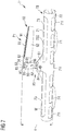
- FIGS. 1 and 2 show a first embodiment of a toilet active substance holder 1 according to the invention with a container 10 in the form of a basket for receiving a drug rod W (this is only in FIG. 6 shown schematically).
- the toilet active substance holder 1 is therefore also referred to below as a toilet bowl 1, without restricting generality.
- the basket-like container 10 has a relatively thin, elongated, substantially cylindrical shape extending along a longitudinal axis L.
- the container 10 here consists of two half-shells 11, 12 or halves, a first, front half shell 11, which points in a hung in the toilet bowl state to the center of the toilet bowl, and a second, rear or rear half-shell 12, which in the hinged Condition to the wall of the toilet bowl has.
- the front half-shell 11 there are a plurality of circular viewing apertures 15, through which the user can also see the active ingredient rod W in the suspended state of the WC-active substance holder 1 and in particular can recognize whether it is consumed or not.
- the front half-shell 11 has an integrally formed tab-shaped bulge 21 in the middle region, here exactly in the middle between the front-side ends of the container 10.
- top and bottom or “top” and “bottom” are always to be understood in relation to the suspended state of the toilet active ingredient holder in a toilet bowl. That is, the top is the side on which the hanger 30 is located, on which the toilet active ingredient holder 1 is hung on the edge of the toilet bowl.
- the rear half-shell 12 At the lower edge of the front half shell 11, this is connected to the rear half shell 12 via three film hinges 11f. These film hinges 11f are arranged along a folding axis K which runs parallel to the longitudinal axis L of the container 10. To these film hinges 11f, the rear half-shell 12, after in the front half shell 11, a drug rod W was inserted, are easily folded up. In the middle of the rear half-shell 12 is located at the upper edge of a tab 18 which has a closure opening 19, in which a arranged on the tab-like bulge 21 of the front half-shell 11, mushroom-shaped closure pin 24 can be pressed to the two half-shells 11, 12 merge at the top. At the front ends are also for coupling in each case clamping pin 17 in the interior of the rear half-shell 12, which engage in corresponding sleeves 16 (here slotted sleeves) at the corresponding positions in the front half shell 11 to hold the basket 10 well on the front pages ,
- the rear half-shell 12 has relatively large water inlet openings 13 in an upper area, which are in principle formed by correspondingly large, longer cut-outs from the upper edge of the rear half-shell (which in the in FIG. 1 shown unfolded state below) are formed.
- water outlet openings 14 In the lower part of the rear half-shell 12 which is suspended in the suspended state, there are a plurality of oblong holes as water outlet openings 14.
- this tongue 23 is attached to a certain extent elastically with the tab-like protrusion 21 of the protrusion member 20 at the upper edge 10O of the basket 10. This provides flexibility in terms of the height of the basket to accommodate different edge shapes of the various toilet bowls.
- a second component of the toilet active substance holder 1 is a suspension bracket 30, which here has a plurality of bracket sections 31, 32, 33, which are helically folded into one another and are each connected to one another via elastically bendable sections, d. H. the entire hanger 30 can be opened by hand, so as to form a U-shaped profile with which the hanger 30 can be hung over the edge or the edge of a toilet key.
- an attachment portion 34 connects at the end, with which it is coupled to the projection element 20 of the container 10 via a pivot connection 25, 35, as will be explained below.
- the suspension bracket 30 can be moved from a first position P1 (transport position) as shown in FIG. 1 is shown, pivot in a second position P2 (position of use), as in FIG. 2 is shown.
- first position P1 is the hanger next to the container 10 of the toilet active ingredient holder 1.
- the consumer brings the hanger 30 by pivoting about the pivot connection 25, 35 in the second position P2, in which the hanger 30 extends in a longitudinal direction H substantially perpendicular to the longitudinal axis L of the container or basket 10, and can hook the toilet bowl 1 in the toilet bowl.
- the tongue has a hole 25 for the pivot connection 25, 35 in a central region, here exactly on its center line, just above the transition section 22.
- this hole 25 is a mushroom-shaped in the longitudinal section of pivot 35, which is arranged at the connecting portion 34 of the hanger 30 at the folded to the other further bracket sections 31, 32 side inserted to the hanger 30 with the container or basket 10 on the projection element 20th to pair.
- this pivot connection 25, 35 on the tongue 23 is the pivot axis S, by which the hanger 30 can be pivoted relative to the container 10, at a relatively large distance above the top 10O of the container 10. The distance is from the top of the container to the axis of rotation here preferably about 22 mm.
- This clamping slot 26 extends along a circular arc portion of an outer edge of the tongue 23, which faces in the direction of the longitudinal axis L of the basket or container 10, to about the middle of the tongue 23 above the pivot connection 25, 35.
- a guide and clamping pin 36 is arranged, which may be formed in the same manner as the pivot 35.
- FIGS. 3 and 4 show a similar, but in detail slightly changed inventive toilet bowl 1 '.
- this toilet bowl 1 has a cup-like container or a basket 40 with two half-shells 41, 42, which are coupled to each other via film hinges 41 f at an underside of the front half-shell 41.
- the rear half-shell 42 can be folded upwards around the hinged axis K by means of an active-substance rod around these film hinges 41f.
- a connection is effected by means of a closure opening 49 on a tab 48 arranged in the middle region on the second rear half shell 42 by pressing into the closure opening 49 a closure pin 54 which is arranged on a tab-like bulge 51 on the upper edge of the front half shell 41 is.
- pins 47 which engage in corresponding holes 46 on the front half-shell 41, to ensure a good connection at the front ends.
- these pins 47 are integrated as flat elements of the frontal wall of the second half-shell 42, and accordingly, the associated holes 46 are integrated into the frontal wall of the first half-shell 41.
- the rear half-shell 42 there are also upper-side larger cut-outs for forming water inlet openings 43 and lower-side oblong holes as water outlet openings 44.
- the front half-shell 41 there are again several circular viewing openings 45.
- a tongue-like section 53 or a tongue 53 is also arranged here on the strap-like protrusion 51 via a transition section 52, in which center above of the locking pin 54 is a hole 55 for a pivot connection 55, 65 to couple a hanger 60 with the container 40.
- the hanger 60 is in this case configured in a similar manner as the hanger 30 in the first embodiment.
- This also has, folded spirally, three strap sections 61, 62, 63, which are elastically bendable interconnected, and at the end of the outer last section 63, a connection portion 64, on which two pins 65, 66 are arranged.
- These pins 65, 66 also point to the side on which the other strap sections 61, 62, of the suspension bracket 60 are located.
- Both pins 65, 66 are each formed in a longitudinal section again mushroom-shaped.
- the first pin 65 is the pivot pin 65 for the pivot connection 55, 65 and the second pin 66 again serves as a clamping pin.
- the pivot connection 55, 65 differs from the pivot connection in the embodiment according to FIG.
- the hole 55 in the tongue 53 is formed as a slot 55, in which case the length of this elongated hole 55 corresponds approximately to twice the width of the slot 55.
- the longitudinal direction of the slot 55 extends in the longitudinal direction H of the hanger 60 in the folded-up position, ie in the second position P2 (see FIG. 4 ).
- the insertion slot 56 (unlike the insertion or clamping slot 26 of the first embodiment) to form the hook 57 at the end of the tongue 53 is provided with a extending in an extension of the longitudinal axis of the slot 55 slot portion 56 a, which on a Slot edge has a locking lug 59.
- the consumer can therefore after the folding up of the hanger 60 from the first position P1 in the use position P2 pull the hanger 60 in the slot 55 upwards, whereby the clamping pin 66, which is also guided here when folding along the leading edge 58, then behind the locking lug 59 in the slot portion 56a engages.
- an even better protection against folding back of the hanger 60 is achieved in the first position P1.
- a locking element (not shown), for example a detent recess and / or latch, be arranged to the hanger 60 in the in FIG. 3 to lock shown position, for example by the clamping pin 66 is located in this locking recess or behind the locking lug.
- FIGS. 5 to 7 show a third variant of a toilet bowl according to the invention 1 ".
- the basket-like container 70 and the basket 70 is, apart from the special configuration of the connection with the hanger 90, in the same manner as the basket 40 according to the embodiment of Figures 3 and 4 designed.
- the second rear half-shell 72 has generous cut-outs for forming water inlet openings 73 in a top area in the folded-up state and corresponding elongated holes for forming water outlet openings 74 on the bottom side. Sight openings 75 are again in the front half-shell.
- the projection element 80 for coupling to the hanger 90 also has here again at the tab-like bulge 81 at the upper edge of the first half-shell 71 an adjoining, upwardly extending arcuate transition portion 82 and then upwardly a tongue-like portion or a tongue 83 , Centered on this tongue 83 is again the pivot connection 85, 95, the pivot axis S perpendicular to the longitudinal axis H of the hanger in the second position P2 (see FIG. 7 ) and to the longitudinal axis L of the container 70 stands.
- pivot pin 95 is again disposed on a coupling portion 94 of the hanger 90, which in turn is located at the outer end of a bracket portion 93, since this hanger 90 has three in the initial state superimposed, elastically bendable coupled to each other bow sections 91, 92, 93, which are spiral-folded into each other.
- a difference to the WC-drug holders according to the first two embodiments is here in the latching of the hanger 90 in the folded-up second position P2.
- a spring element 86 located above the pivot connection 85, 95 at the outermost end of the tongue 83 to form a locking means 86, a spring element 86 in the form of a spring-shaped bracket.
- This is achieved by the outer end of the tongue 83 is provided with a small indentation 88 and in the area behind the recess 88 is a wide recess 87, so that the end portion of the tongue 83 is formed as a kind of thin, W-shaped web , Since the tongue 83 is made of plastic, this thin W-shaped web is somewhat resilient to some extent.
- FIG. 6 the toilet bowl 1 "is shown after inserting the cylindrical active substance bar W, just before the rear half-shell 72 is folded up about the axis K and coupled at the top and at the end sides to the front half-shell 71.
- This filling with an active ingredient bar W takes place the embodiments according to the FIGS. 1 to 4 in the same way.
- the length I of a cylindrical active substance rod W along its longitudinal axis L '(which is arranged coaxially to the longitudinal axis of the container 70) is preferably at least 115 mm, particularly preferably at least 140 mm, very particularly preferably at least 150 mm.
- the maximum length is preferably 245 mm, more preferably at most 195 mm, particularly preferably at most 180 mm.
- the length of the drug rod W is about 150 mm.
- the diameter d of the active substance rod W is preferably at least 10 mm and preferably at most 15 mm, in a preferred variant about 12 mm, in another preferred variant about 14 mm.
- the length to diameter ratio of the active ingredient rod W is at least preferably 7: 1, preferably 10: 1, more preferably about 11: 1, particularly preferably about 15: 1.
- the length of the entire cup-like container is inside about 170 mm and outside about 173 mm.
- a length of the drug rod W about 150 mm, the interior of the container in the direction of its longitudinal axis L to about 88% occupied by the drug rod W.
- FIG. 7 is then the container 70 and the basket 70 to see in the folded state with a drug rod W therein, in which case the hanger 90 is still in the transport position P1.
- the toilet bowl is 1 "blown.
- the total width a of the toilet active agent holder 1 "with the hanger 90 in the transport position P2 is from the lower edge of the container 70 (including the film hinges) up to the end facing away from the container 70 of the projection element 80, that is, to the outermost end of the tongue 83, here about 50 mm.
- FIG. 8 is then the toilet bowl 1 "with the hanger 90 to see after pivoting in the use position P2, as it can then be hooked by the consumer at the edge of the toilet bowl in this.
- an inventive WC active ingredient holder can be accommodated on a very narrow blister card.
- a WC active ingredient holder can be accommodated on a blister card with a width of only 65 mm (the width is considered to be the dimension perpendicular to the perpendicular of a blister card suspended from the usual suspension opening, in which case the longitudinal axis of the blister card Container runs from top to bottom on the blister card). If two such toilet active ingredient holder on a blister card (eg staggered to each other, arranged side by side with the swung-hanger), a blister card with a width of 95 mm is sufficient.
Landscapes
- Health & Medical Sciences (AREA)
- Public Health (AREA)
- Epidemiology (AREA)
- Life Sciences & Earth Sciences (AREA)
- Engineering & Computer Science (AREA)
- Hydrology & Water Resources (AREA)
- Water Supply & Treatment (AREA)
- Bidet-Like Cleaning Device And Other Flush Toilet Accessories (AREA)
- Details Of Rigid Or Semi-Rigid Containers (AREA)
Applications Claiming Priority (1)
| Application Number | Priority Date | Filing Date | Title |
|---|---|---|---|
| DE102016100293.3A DE102016100293A1 (de) | 2016-01-11 | 2016-01-11 | WC-Wirkstoffhalter |
Publications (2)
| Publication Number | Publication Date |
|---|---|
| EP3190238A2 true EP3190238A2 (fr) | 2017-07-12 |
| EP3190238A3 EP3190238A3 (fr) | 2017-08-23 |
Family
ID=57681475
Family Applications (1)
| Application Number | Title | Priority Date | Filing Date |
|---|---|---|---|
| EP16207379.5A Withdrawn EP3190238A3 (fr) | 2016-01-11 | 2016-12-29 | Excipient de wc |
Country Status (2)
| Country | Link |
|---|---|
| EP (1) | EP3190238A3 (fr) |
| DE (1) | DE102016100293A1 (fr) |
Cited By (3)
| Publication number | Priority date | Publication date | Assignee | Title |
|---|---|---|---|---|
| USD912761S1 (en) | 2019-06-07 | 2021-03-09 | S. C. Johnson & Son, Inc. | Toilet rim-block |
| USD914131S1 (en) | 2019-06-07 | 2021-03-23 | S. C. Johnson & Son, Inc. | Toilet rim-block holder |
| USD923139S1 (en) | 2019-06-07 | 2021-06-22 | S. C. Johnson & Son, Inc. | Set of toilet rim-blocks |
Citations (2)
| Publication number | Priority date | Publication date | Assignee | Title |
|---|---|---|---|---|
| DE2721348A1 (de) | 1977-05-12 | 1978-11-23 | Henkel Kgaa | Halterung fuer wc-desodorantien |
| DE2914798C2 (de) | 1978-04-12 | 1987-01-15 | L'oreal, Paris | Halterung für blockförmige, wasserlösliche Produkte zur Desinfektion und Deodorierung von Toilettenschüsseln |
Family Cites Families (10)
| Publication number | Priority date | Publication date | Assignee | Title |
|---|---|---|---|---|
| GB288878A (en) * | 1927-08-08 | 1928-04-19 | Henry Holden | Improvements in disinfecting and deodorising devices for use in connection with the flushing systems for water closets, lavatories and the like |
| DE7332236U (de) * | 1973-09-05 | 1973-11-29 | Dietsche R Kg | Vorrichtung zum reinigen von wasserklosettbecken |
| FR2258320A1 (en) * | 1974-01-22 | 1975-08-18 | Oreal | Water-soluble disinfecting and, or deodorizing stick - for clipping on lavatory pan |
| DE2805171A1 (de) * | 1978-02-08 | 1979-08-09 | Collo Gmbh | Vorrichtung zum reinigen und/oder desinfizieren von toilettenbecken u.dgl. sowie zur luftverbesserung in toilettenraeumen |
| FR2435657A1 (fr) * | 1978-09-05 | 1980-04-04 | Oreal | Conditionnement d'un baton de produit desinfectant et desodorisant pour cuvette de toilettes |
| DE4428970A1 (de) * | 1994-08-16 | 1996-02-22 | Buck Chemie Gmbh | WC-Körbchen |
| AU2005268631B9 (en) * | 2004-08-04 | 2010-01-21 | Reckitt Benckiser Llc | Dispensing device |
| BRPI0702926B1 (pt) * | 2006-06-23 | 2017-10-31 | Reckitt Benckiser Llc | "method for the production of washing dispensing devices without cage" |
| GB0918759D0 (en) * | 2009-10-27 | 2009-12-09 | Reckitt Benckiser Inc | Hanger for a lavatory treatment device |
| CN203947547U (zh) * | 2013-09-30 | 2014-11-19 | S.C.约翰逊父子公司 | 洁厕装置及洁厕块 |
-
2016
- 2016-01-11 DE DE102016100293.3A patent/DE102016100293A1/de not_active Withdrawn
- 2016-12-29 EP EP16207379.5A patent/EP3190238A3/fr not_active Withdrawn
Patent Citations (2)
| Publication number | Priority date | Publication date | Assignee | Title |
|---|---|---|---|---|
| DE2721348A1 (de) | 1977-05-12 | 1978-11-23 | Henkel Kgaa | Halterung fuer wc-desodorantien |
| DE2914798C2 (de) | 1978-04-12 | 1987-01-15 | L'oreal, Paris | Halterung für blockförmige, wasserlösliche Produkte zur Desinfektion und Deodorierung von Toilettenschüsseln |
Cited By (3)
| Publication number | Priority date | Publication date | Assignee | Title |
|---|---|---|---|---|
| USD912761S1 (en) | 2019-06-07 | 2021-03-09 | S. C. Johnson & Son, Inc. | Toilet rim-block |
| USD914131S1 (en) | 2019-06-07 | 2021-03-23 | S. C. Johnson & Son, Inc. | Toilet rim-block holder |
| USD923139S1 (en) | 2019-06-07 | 2021-06-22 | S. C. Johnson & Son, Inc. | Set of toilet rim-blocks |
Also Published As
| Publication number | Publication date |
|---|---|
| EP3190238A3 (fr) | 2017-08-23 |
| DE102016100293A1 (de) | 2017-07-13 |
Similar Documents
| Publication | Publication Date | Title |
|---|---|---|
| DE3752243T2 (de) | Befestigungsanordnung | |
| DE3445935C2 (fr) | ||
| DE2327100A1 (de) | Scharnier, insbesondere moebelscharnier | |
| DE112018003177T5 (de) | Kopfstützenbewegungsvorrichtung | |
| WO1996025340A1 (fr) | Chaine de clips de fermeture et dispositif et procede de fermeture desdits clips | |
| DE102016100293A1 (de) | WC-Wirkstoffhalter | |
| AT393818B (de) | Schachtel mit kantenverriegelung | |
| DE19536155A1 (de) | Einrichtung zum Absorbieren des elektrischen Rauschens | |
| EP0697186B1 (fr) | Emballage en petits pour toilettes | |
| DE8023994U1 (de) | Vorrichtung zum Auspressen und Aufrollen von Tuben insbesondere Kunststofftuben | |
| WO2023274679A1 (fr) | Organe d'accouplement | |
| DE102014102626A1 (de) | Kettenglied für eine Energieführungskette | |
| DE3230312C2 (fr) | ||
| DE2721348C2 (de) | Halterung für WC-Desodorantien | |
| DE2756818A1 (de) | Einstueckiger aufhaenger fuer behaelter | |
| DE102005058969B4 (de) | Verriegelungsvorrichtung für Steckerteil und Grundleiste eines elektrischen Steckverbinders | |
| DE19518586C1 (de) | Hohlkörper für die Betonbauinstallation | |
| DE19726892C2 (de) | Hohlkörper für die Betonbauinstallation | |
| AT395450B (de) | Vorrichtung zur abgabe eines wasserloeslichen mittels in das spuelwasser | |
| DE2943736A1 (de) | Isolation fuer flachsteckhuelsen | |
| DE10149472B4 (de) | Blindabdeckstreifen zum Verschließen von Zähler- oder Verteilerschranköffnungen | |
| EP3434156A1 (fr) | Dispositif d'insertion des coulisseaux de rideau dans un rail de guidage | |
| DE202009012010U1 (de) | Interdentalbürste | |
| DE20219460U1 (de) | Kassette | |
| DE2555711A1 (de) | Beutelhalter |
Legal Events
| Date | Code | Title | Description |
|---|---|---|---|
| PUAI | Public reference made under article 153(3) epc to a published international application that has entered the european phase |
Free format text: ORIGINAL CODE: 0009012 |
|
| AK | Designated contracting states |
Kind code of ref document: A2 Designated state(s): AL AT BE BG CH CY CZ DE DK EE ES FI FR GB GR HR HU IE IS IT LI LT LU LV MC MK MT NL NO PL PT RO RS SE SI SK SM TR |
|
| AX | Request for extension of the european patent |
Extension state: BA ME |
|
| PUAL | Search report despatched |
Free format text: ORIGINAL CODE: 0009013 |
|
| AK | Designated contracting states |
Kind code of ref document: A3 Designated state(s): AL AT BE BG CH CY CZ DE DK EE ES FI FR GB GR HR HU IE IS IT LI LT LU LV MC MK MT NL NO PL PT RO RS SE SI SK SM TR |
|
| AX | Request for extension of the european patent |
Extension state: BA ME |
|
| RIC1 | Information provided on ipc code assigned before grant |
Ipc: E03D 9/03 20060101AFI20170717BHEP Ipc: E03D 9/02 20060101ALI20170717BHEP |
|
| 17P | Request for examination filed |
Effective date: 20180212 |
|
| RBV | Designated contracting states (corrected) |
Designated state(s): AL AT BE BG CH CY CZ DE DK EE ES FI FR GB GR HR HU IE IS IT LI LT LU LV MC MK MT NL NO PL PT RO RS SE SI SK SM TR |
|
| 17Q | First examination report despatched |
Effective date: 20191014 |
|
| STAA | Information on the status of an ep patent application or granted ep patent |
Free format text: STATUS: THE APPLICATION HAS BEEN WITHDRAWN |
|
| 18W | Application withdrawn |
Effective date: 20200612 |