EP3191282B1 - Procédé de commande d'un système de scie murale par sciage en long - Google Patents
Procédé de commande d'un système de scie murale par sciage en long Download PDFInfo
- Publication number
- EP3191282B1 EP3191282B1 EP15759753.5A EP15759753A EP3191282B1 EP 3191282 B1 EP3191282 B1 EP 3191282B1 EP 15759753 A EP15759753 A EP 15759753A EP 3191282 B1 EP3191282 B1 EP 3191282B1
- Authority
- EP
- European Patent Office
- Prior art keywords
- saw
- cut
- corner
- blade
- sin
- Prior art date
- Legal status (The legal status is an assumption and is not a legal conclusion. Google has not performed a legal analysis and makes no representation as to the accuracy of the status listed.)
- Active
Links
Images




Classifications
-
- B—PERFORMING OPERATIONS; TRANSPORTING
- B28—WORKING CEMENT, CLAY, OR STONE
- B28D—WORKING STONE OR STONE-LIKE MATERIALS
- B28D7/00—Accessories specially adapted for use with machines or devices of the preceding groups
- B28D7/005—Devices for the automatic drive or the program control of the machines
-
- B—PERFORMING OPERATIONS; TRANSPORTING
- B28—WORKING CEMENT, CLAY, OR STONE
- B28D—WORKING STONE OR STONE-LIKE MATERIALS
- B28D1/00—Working stone or stone-like materials, e.g. brick, concrete or glass, not provided for elsewhere; Machines, devices, tools therefor
- B28D1/02—Working stone or stone-like materials, e.g. brick, concrete or glass, not provided for elsewhere; Machines, devices, tools therefor by sawing
- B28D1/04—Working stone or stone-like materials, e.g. brick, concrete or glass, not provided for elsewhere; Machines, devices, tools therefor by sawing with circular or cylindrical saw-blades or saw-discs
- B28D1/042—Working stone or stone-like materials, e.g. brick, concrete or glass, not provided for elsewhere; Machines, devices, tools therefor by sawing with circular or cylindrical saw-blades or saw-discs the saw blade being carried by a pivoted lever
-
- B—PERFORMING OPERATIONS; TRANSPORTING
- B28—WORKING CEMENT, CLAY, OR STONE
- B28D—WORKING STONE OR STONE-LIKE MATERIALS
- B28D1/00—Working stone or stone-like materials, e.g. brick, concrete or glass, not provided for elsewhere; Machines, devices, tools therefor
- B28D1/02—Working stone or stone-like materials, e.g. brick, concrete or glass, not provided for elsewhere; Machines, devices, tools therefor by sawing
- B28D1/04—Working stone or stone-like materials, e.g. brick, concrete or glass, not provided for elsewhere; Machines, devices, tools therefor by sawing with circular or cylindrical saw-blades or saw-discs
- B28D1/044—Working stone or stone-like materials, e.g. brick, concrete or glass, not provided for elsewhere; Machines, devices, tools therefor by sawing with circular or cylindrical saw-blades or saw-discs the saw blade being movable on slide ways
-
- B—PERFORMING OPERATIONS; TRANSPORTING
- B28—WORKING CEMENT, CLAY, OR STONE
- B28D—WORKING STONE OR STONE-LIKE MATERIALS
- B28D1/00—Working stone or stone-like materials, e.g. brick, concrete or glass, not provided for elsewhere; Machines, devices, tools therefor
- B28D1/02—Working stone or stone-like materials, e.g. brick, concrete or glass, not provided for elsewhere; Machines, devices, tools therefor by sawing
- B28D1/04—Working stone or stone-like materials, e.g. brick, concrete or glass, not provided for elsewhere; Machines, devices, tools therefor by sawing with circular or cylindrical saw-blades or saw-discs
- B28D1/045—Sawing grooves in walls; sawing stones from rocks; sawing machines movable on the stones to be cut
Definitions
- the present invention relates to a method for controlling a wall sawing system when making a separating cut according to the preamble of claim 1.
- Examples of wall saw systems are also available from the US 2013/180371 A1 , WO 2014/124912 A1 , US 2012/180773 A1 , US 6 170 478 B1 , WO 2014/128095 A1 or WO 2014/124931 A1 known. From EP 1 693 173 B1 A method for controlling a wall sawing system when creating a separating cut in a workpiece between a first end point and a second end point is known.
- the wall sawing system comprises a guide rail and a wall saw with a saw head, a motorized feed unit that moves the saw head parallel to a feed direction along the guide rail, and at least one saw blade that is attached to a saw arm of the saw head and driven about a rotational axis by a drive motor.
- the saw arm is designed to be pivotable about a pivot axis by means of a pivot motor. By pivoting the saw arm about the pivot axis, the penetration depth of the saw blade into the workpiece is changed.
- the motorized feed unit comprises a guide carriage and a feed motor, with the saw head being mounted on the guide carriage and moved along the guide rail via the feed motor.
- a sensor device with a pivot angle sensor and a displacement sensor is provided to monitor the wall sawing system.
- the pivot angle sensor measures the current pivot angle of the saw arm
- the displacement sensor measures the current position of the saw head on the guide rail. The measured values for the current swivel angle of the saw arm and the current position of the saw head are regularly transmitted to a control unit of the wall saw.
- the known method for controlling a wall sawing system is divided into a preparatory section and a processing of the separating cut, which is controlled by the control unit.
- the operator defines at least the saw blade diameter, the positions of the first and second end points in the feed direction, and the final depth of the separating cut; further parameters can include the material of the workpiece to be processed. workpiece and the dimensions of embedded reinforcing bars.
- the control unit determines a suitable main cutting sequence of main cuts for the separating cut, wherein the main cutting sequence comprises at least a first main cut with a first main cutting angle of the saw arm and a first diameter of the saw blade used, as well as a subsequent second main cut with a second main cutting angle of the saw arm and a first diameter of the saw blade used.
- the known method for controlling a wall sawing system has the disadvantage that no details are disclosed regarding the corner processing of an end point defined as an obstacle and the processing parameters of the wall saw are adapted to the corner processing.
- the object of the present invention is to develop a method for controlling a wall sawing system in which the corner processing of an obstacle is carried out under the control of the control unit of the wall saw.
- the corner cutting sequence is performed between the penultimate main cut and the last main cut, or the corner cutting sequence is performed after the last main cut.
- an additional start position and an end position are defined for the corner cutting sequence.
- the number of corner cuts that are necessary depends, among other things, on the specification of the saw blade, the material properties of the workpiece and the power and torque of the drive motor for the saw blade.
- the corner cutting angles can be set by the operator or the control unit of the wall sawing system sets the corner cutting angles depending on various boundary conditions. For the method according to the invention, the corner cutting angles represent an input variable that is used to control the wall saw.
- a saw arm length of the saw arm defined as the distance between the swivel axis of the saw arm and the rotation axis of the saw blade, and a distance between the swivel axis and the top surface of the workpiece are also specified.
- the control unit For controlled machining of a separating cut, the control unit must know various parameters. These include the saw arm length, which represents a fixed, device-specific dimension of the wall saw, and the vertical distance between the swivel axis and the surface of the workpiece, which depends not only on the geometry of the wall saw but also on the geometry of the guide rail used.
- the first end point is defined as an obstacle and a first end position is calculated by the control unit for the corner cutting sequence, whereby the swivel axis in the first end position has a spatial coordinate of X(E 1 ) + D m /2 - ⁇ sin( ⁇ m ) for
- the pivot axis in the first initial position has a spatial coordinate of X(E 1 ) + D 1,n /2 - ⁇ sin( ⁇ 1,n ) for
- the first initial position ensures that the pivoting movement takes place in all overlap angles of the overlap sequence before the first end point and that the first end point is not exceeded.
- the penultimate main cut is carried out with a blade guard and, before the start of the controlled machining, an assembly distance ⁇ assembly and a penultimate width for the blade guard used in the penultimate main cut are additionally determined, wherein the penultimate width is composed of a first distance of the rotation axis to the first blade guard edge and a second distance of the rotation axis to the second blade guard edge.
- the controlled processing is interrupted by the control unit and the wall saw is moved by the control unit into a first parking position.
- the swivel axis has a location coordinate of X(E 1 ) + maximum value of [B 1,m-1 + ⁇ Montage , B 1,m-1 - ⁇ ⁇ sin( ⁇ m )] for
- the wall saw After resuming controlled machining, the wall saw is positioned in a first resumption position, which corresponds to the first parking position. If the control unit determines a resumption position in addition to the parking position, the operator can move the wall saw from the parking position along the guide rail after the interruption using the motor-driven feed unit. The ability to move the wall saw from the parking position is advantageous for vertical or diagonal cuts in a wall where the parking position is located above a manageable assembly position. After resuming, the control unit checks the current position of the wall saw using the position sensor. If the current position deviates from the resumption position, the wall saw is moved to the resumption position.
- the second end point is defined as an obstacle and a second end position is calculated by the control unit for the corner cutting sequence, whereby the swivel axis in the second end position has a spatial coordinate of X(E 2 ) - D m /2 - ⁇ sin( ⁇ m ) for
- the pivot axis in the second initial position has a spatial coordinate of X(E 2 ) - D 2,n /2 - ⁇ sin( ⁇ 2,n ) for
- the second initial position ensures that the pivoting movement takes place in all corner cutting angles of the corner cutting sequence before the second end point and that the second end point is not exceeded.
- the last main cut is carried out with a blade guard and, before the start of the controlled machining, an assembly distance ⁇ assembly and a final width for the blade guard used in the last main cut are additionally determined, wherein the final width is determined from a first distance of the rotation axis to the first blade guard edge and a second distance of the axis of rotation to the second blade guard edge.
- the controlled processing is interrupted by the control unit and the wall saw is moved by the control unit into a second parking position.
- the pivot axis has a spatial coordinate of X(E 2 ) - maximum value of [B 2,m + ⁇ Montage , B 2,m + ⁇ sin( ⁇ m )] for
- FIG. 1 shows a wall sawing system 10 with a guide rail 11, a tool 12 arranged displaceably on the guide rail 11 and a remote control 13.
- the tool is designed as a wall saw 12 and comprises a processing unit 14 and a motorized feed unit 15.
- the processing unit is designed as a saw head 14 and comprises a processing tool 16 designed as a saw blade, which is fastened to a saw arm 17 and is driven by a drive motor 18 about a rotation axis 19 .
- the saw blade 16 is surrounded by a blade guard 21 , which is attached to the saw arm 17 by means of a blade guard holder.
- the saw arm 17 is designed to be pivotable about a pivot axis 23 by a pivot motor 22.
- the pivot angle ⁇ of the saw arm 17, together with a saw blade diameter D of the saw blade 16, determines how deeply the saw blade 16 penetrates a workpiece 24 to be machined.
- the drive motor 18 and the pivot motor 22 are arranged in a device housing 25.
- the motorized feed unit 15 comprises a guide carriage 26 and a feed motor 27, which in the exemplary embodiment is also arranged in the device housing 25.
- the saw head 14 is attached to the guide carriage 26 and is designed to be displaceable along the guide rail 11 in a feed direction 28 via the feed motor 27.
- a control unit 29 for controlling the saw head 14 and the motorized feed unit 15 is arranged in the device housing 25, in addition to the motors 19, 22, 27, a control unit 29 for controlling the saw head 14 and the motorized feed unit 15 is arranged in the device housing 25, in addition to the motors 19, 22, 27, a control unit 29 for controlling the saw head 14 and the motorized feed unit 15 is arranged.
- a sensor device with multiple sensor elements is provided to monitor the wall sawing system 10 and the machining process.
- a first sensor element 32 is configured as a swivel angle sensor, and a second sensor element 33 is configured as a displacement sensor.
- the swivel angle sensor 32 measures the current swivel angle of the saw arm 17, and the displacement sensor 33 measures the current position of the saw head 14 on the guide rail 11. The measured values are transmitted from the swivel angle sensor 32 and displacement sensor 33 to the control unit 29 and used to control the wall saw 12.
- the remote control 13 comprises a device housing 35, an input device 36, a display device 37 , and a control unit 38 arranged inside the device housing 35.
- the control unit 38 converts the inputs of the input device 36 into control commands and data, which are transmitted to the wall saw via a first communication connection.
- the first communication connection is designed as a wireless communication connection 41 or as a communication cable 42.
- the wireless communication connection is designed as a radio connection 41, which is created between a first radio unit 43 on the remote control 13 and a second radio unit 44 on the tool device 12.
- the wireless communication connection 41 can be designed in the form of an infrared, Bluetooth, WLAN, or Wi-Fi connection.
- FIG. 2A , B show the guide rail 11 and the wall saw 12 of the wall saw system 10 of the FIG. 1 when creating a separating cut 51 in the workpiece 24 of the workpiece thickness d.
- the separating cut 51 has a final depth T and runs in the feed direction 28 between a first end point E 1 and a second end point E 2 .
- the X direction is defined as a direction parallel to the feed direction 28, with the positive X direction being directed from the first end point E 1 to the second end point E 2
- the Y direction is defined as a direction perpendicular to the X direction into the depth of the workpiece 24.
- the end point of a severance cut can be defined as a free end point without obstacles or as an obstacle. Both end points can be defined as free end points without obstacles, both end points as obstacles, or one end point as a free end point and the other end point as an obstacle. Overlapping may be permitted at a free end point without obstacles. Due to the overlapping, the cutting depth at the end point reaches the final depth T of the severance cut. In the example of the FIG. 2A , B the endpoints E 1 , E 2 form free endpoints without obstacle, whereby an intersection is not permitted at the free first endpoint E 1 and an intersection has occurred at the second endpoint E 2 .
- FIG. 2A shows the saw head 14 in an assembly position X 0 and the saw arm 17 in a home position of 0°.
- the saw head 14 is positioned by the operator in the assembly position X 0 on the guide rail 11 using the guide carriage 26.
- the assembly position X 0 of the saw head 14 lies between the first and second end points E 1 , E 2 and is determined by the position of the pivot axis 23 in the feed direction 28.
- the position of the pivot axis 23 is particularly suitable as a reference position X Ref for monitoring the position of the saw head 14 and controlling the wall saw 12, since the X position of the pivot axis 23 remains unchanged even during the pivoting movement of the saw arm 17.
- a different X position on the saw head 14 can be defined as the reference position, although in this case the distance in the X direction to the pivot axis 23 must also be known.
- the X-positions of the first and second end points E 1 , E 2 are defined in the example by entering partial lengths.
- the distance between the mounting position X 0 and the first end point E 1 determines a first partial length L 1 and the distance between the mounting position X 0 and the second end point E 2 determines a second partial length L 2 .
- the X positions of the end points E 1 , E 2 can be defined by entering a partial length (L 1 or L 2 ) and a total length L as the distance between the end points E 1 , E 2 .
- the separating cut 51 is created in several partial cuts until the desired final depth T is reached.
- the partial cuts between the first and second end points E 1 , E 2 are defined as main cuts, and the cutting sequence of the main cuts is defined as the main cutting sequence. Additional corner processing can be performed at the end points of the separating cut. This is referred to as obstacle processing in the case of an obstacle and as overcut processing in the case of a free end point with overlap.
- the main cutting sequence can be set by the operator, or the control unit of the wall sawing system can determine the main cutting sequence based on several constraints.
- the first main cut also known as the pre-cut
- the subsequent main cuts are generally performed at the same cutting depth, but can also have different cutting depths.
- the constraints typically set by an operator include the cutting depth of the pre-cut, the pre-cut power, and the maximum cutting depth of the subsequent main cuts.
- the control unit can determine the main cutting sequence based on these constraints.
- the main cuts of a separating cut are performed with one saw blade diameter or with two or more saw blade diameters. If multiple saw blades are used, processing generally begins with the smallest saw blade diameter.
- the saw blade 16 In order to be able to mount the saw blade 16 on the saw arm 17, the saw blade 16 must be arranged in the home position of the saw arm 17 above the workpiece 24. Whether this boundary condition is met depends on two device-specific variables of the wall sawing system 10: firstly, a vertical distance ⁇ between the pivot axis 23 of the saw arm 17 and an upper side 53 of the workpiece 24, and secondly, a saw arm length ⁇ of the saw arm 17, which is defined as the distance between the rotation axis 19 of the saw blade 16 and the pivot axis 23 of the saw arm 17.
- the saw blade 16 is arranged in the basic position above the workpiece 24.
- the saw arm length ⁇ is a fixed device-specific size of the wall saw 12, whereas the vertical distance ⁇ between the pivot axis 23 and the surface 53, in addition to the geometry the wall saw 12 also depends on the geometry of the guide rail 11 used.
- the saw blade 16 is mounted on a flange on the saw arm 17 and is driven by the drive motor 18 around the rotation axis 19 during sawing operation.
- the pivot angle is 0° and the rotation axis 19 of the saw blade 16 lies in the depth direction 52 above the pivot axis 23.
- the saw blade 16 is moved from the basic position at 0° into the workpiece 24 by a pivoting movement of the saw arm 17 about the pivot axis 23.
- the saw blade 16 is driven by the drive motor 18 about the rotation axis 19.
- the saw blade 16 should be surrounded by the blade guard 21 during operation.
- the wall saw 12 is operated with or without the blade guard 21.
- the blade guard 21 can be removed. If different saw blade diameters are used to process the separating cut, different blade guards with corresponding blade guard widths are generally also used.
- FIG. 2B shows the saw arm 17, which is inclined in a negative rotation direction 54 at a negative pivot angle - ⁇ .
- the saw arm 17 is adjustable in the negative rotation direction 54 between pivot angles of 0° to -180° and in a positive rotation direction 55 opposite to the negative rotation direction 54 between pivot angles of 0° to +180°.
- FIG. 2B The arrangement of the saw arm 17 shown is referred to as a pulling arrangement when the saw head 14 is moved in a positive feed direction 56. If the saw head 14 is moved in a negative feed direction 57 opposite to the positive feed direction 56, the arrangement of the saw arm 17 is referred to as a pushing arrangement.
- the maximum penetration depth of the saw blade 16 into the workpiece 24 is achieved.
- the swivel movement of the saw arm 17 around the swivel axis 23 shifts the position of the rotation axis 19 in the X and Y directions.
- the displacement of the rotation axis 19 depends on the saw arm length ⁇ and the swivel angle ⁇ of the saw arm 17.
- the displacement ⁇ x in the X direction is ⁇ sin( ⁇ )
- the displacement ⁇ y in the Y direction is ⁇ cos( ⁇ ).
- the saw blade 16 creates a cutting wedge in the workpiece 24 in the form of a circular segment with a height h and a width b.
- the height h of the circular segment corresponds to the penetration depth of the saw blade 16 into the workpiece 24.
- the control of the wall saw 12 during the separating cut depends on whether the end points are defined as obstacles and, in the case of an obstacle, whether the processing is carried out with or without the blade guard 21.
- the control of the wall saw 12 in the method according to the invention is carried out via upper exit points of the saw blade 16 on the upper side 53 of the workpiece 24.
- the upper exit points of the saw blade 16 can be calculated from the reference position X Ref of the pivot axis 23 in the X direction, the displacement path ⁇ x of the rotation axis 19 in the X direction and the width b.
- first upper exit point 58 An upper exit point facing the first end point E 1 is referred to as the first upper exit point 58 and an upper exit point facing the second end point E 2 is referred to as the second upper exit point 59.
- end points E 1 , E 2 are defined as obstacles, it is not possible to cross the end points E 1 , E 2 with the wall saw 12.
- the control of the wall saw 12 in the method according to the invention takes place via the reference position X Ref of the pivot axis 23 and the limitation of the wall saw 12.
- FIG. 3A , B show the wall sawing system 10 during the creation of a separating cut between the first end point E 1 and the second end point E 2 , which are defined as obstacles, wherein the processing takes place without the blade guard 21.
- a first saw blade edge 61 which faces the first end point E 1
- a second saw blade edge 62 which faces the second end point E 2 , form the boundary of the wall saw 12.
- the X-positions of the first and second saw blade edges 61, 62 in the X-direction can be calculated from the reference position X Ref of the pivot axis 23, the displacement path ⁇ x of the rotation axis 19 and the saw blade diameter D.
- FIG. 3A shows the wall saw 12 with the saw arm 17 inclined in the negative direction of rotation 54 at a negative swivel angle - ⁇ (0° to -180°).
- X(61) X Ref + ⁇ sin(- ⁇ ) - D/2
- X(62) X Ref + ⁇ ⁇ sin(- ⁇ ) + D/2 applies.
- 3B shows the wall saw 12 with the saw arm 17 inclined in the positive direction of rotation 55 at a positive pivot angle ⁇ (0° to +180°).
- FIG. 4A , B show the wall saw system 10 during the creation of a separating cut between the first end point E 1 and the second end point E 2 , which are defined as obstacles, with the machining being carried out with the blade guard 21.
- a first blade guard edge 71 which faces the first end point E 1
- a second blade guard edge 72 which faces the second end point E 2 , form the boundary of the wall saw 12.
- FIG. 4A shows the wall saw 12 with the saw arm 17 inclined at a negative swivel angle - ⁇ (0° to -180°) and the mounted blade guard 21 of blade guard width B.
- the distances of the rotation axis 19 to the blade guard edges 71, 72 are determined before the start of the controlled machining, whereby the distance to the first blade guard edge 71 is referred to as the first distance B a and the distance to the second blade guard edge 72 is referred to as the second distance B b .
- FIG. 4B shows the wall saw 12 with the saw arm 17 inclined at a positive swivel angle ⁇ (0° to +180°) and the mounted blade guard 21 of blade guard width B.
- FIG. 2A , B show a cut between two endpoints E 1 , E 2 , which are defined as free endpoints without obstacle
- FIG. 3A , B and 4A, B show a separating cut between two end points E 1 , E 2 , which are defined as obstacles.
- separating cuts are also possible in which one end point is defined as an obstacle and the other end point represents a free end point without an obstacle, whereby the control of the wall saw is carried out via the upper exit point of the saw blade at the free end point and via the saw blade edge (processing without blade guard 21) or the blade guard edge (processing with blade guard 21) at the obstacle.
- the first upper exit point 58, the first saw blade edge 61 and the first blade protection edge 71 are collectively referred to as the "first boundary" of the wall saw 12 and the second upper exit point 59, the second saw blade edge 62 and the second blade protection edge 72 are collectively referred to as the "second boundary”.
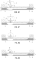
- FIGS. 5A-N show the wall saw system 10 of the FIG. 1 with the guide rail 11 and the wall saw 12 when creating a separating cut of the final depth T in the workpiece 24 between the first end point E 1 , which is defined as an obstacle, and the second end point E 2 , which is defined as an obstacle.
- the separating cut comprises a main cutting sequence of several main cuts performed between the first end point E 1 and the second end point E 2 , a first corner cutting sequence for the first end point E 1 and a second corner cutting sequence for the second end point E 2 .
- the main cutting sequence comprises a first main cut with a first main cutting angle ⁇ 1 of the saw arm 17, a first diameter D 1 of the saw blade used and a first width B 1 of the blade guard used, a second main cut with a second main cutting angle ⁇ 2 of the saw arm 17, a second diameter D 2 of the saw blade used and a second width B 2 of the blade guard used and a third main cut with a third main cutting angle ⁇ 3 of the saw arm 17, a third diameter D 3 of the saw blade used and a third width B 2 of the blade guard used.
- the first, second, and third main cuts are performed using the saw blade 16 and the associated blade guard 21. Therefore, the diameters D 1 , D 2 , D 3 of the main cuts correspond to the saw blade diameter D of the saw blade 16, and the widths B 1 , B 2 , B 3 of the main cuts correspond to the blade guard width B of the symmetrical blade guard.
- the main cuts can be performed by multiple saw blades with different saw blade diameters.
- the method according to the invention comprises a method step for changing the saw blade to a different saw blade diameter.
- Three process variants are suitable for processing the main cuts, which differ from one another in terms of the processing quality of the separating cut and the required processing time. Controlling the wall saw during the execution of the main cutting sequence is not part of the process according to the invention. Depending on the requirements of the separating cut, the operator determines which process variant will be used for the main cutting sequence before starting the controlled processing.
- the main cuts are performed with a pulling saw arm 17.
- the pulling arrangement of the saw arm 17 enables stable guidance of the saw blade 16 during processing and a narrow cutting gap.
- the saw arm 17 is arranged alternately in a pulling and pushing position, with the first main cut being performed in a pulling arrangement.
- a separating cut in which the saw arm 17 is arranged alternately in a pulling and pushing position has the advantage that the downtime required for positioning the saw head 14 and pivoting the saw arm 17 is reduced compared to a pulling arrangement.
- the saw head 14 In each main cut of the first process variant, the saw head 14 is positioned, the saw arm 17 is pivoted to the main cutting angle, machining in a first feed direction, the saw head 14 is stopped, the saw arm 17 is pivoted to the negative main cutting angle, and the main cut is machined in a second, opposite feed direction.
- the saw head 14 In each main cut of the second process variant, the saw head 14 is positioned, the saw arm 17 is pivoted to the main cutting angle, machining in a feed direction, and the saw head 14 is stopped in a position where the upper exit point coincides with the end point.
- the third process variant differs from the second process variant in that the last process step of a main cut (stopping) and the first process step of the following main cut (positioning) are combined. The saw head 14 is stopped in a position calculated so that the upper exit point coincides with the end point after the pivoting movement of the saw arm 17 into the main cutting angle of the following main cut.
- the main cuts of the main cutting sequence are carried out with a saw arm 17 which is arranged alternately in a pulling and pushing position.
- the processing of the separating cut begins at the first end point E 1 .
- the saw head 14 is positioned in a starting position X Start in which the pivot axis 23 is at a distance of B/2 - ⁇ sin(- ⁇ 1 ) from the first end point E 1.
- the saw arm 17 is pivoted from the basic position at 0° in the negative direction of rotation 54 into the negative first main cutting angle - ⁇ 1.
- the first blade guard edge 71 of the blade guard 21 coincides with the first end point E 1 .
- the saw head 14 is moved with the saw arm 17 inclined at the negative first main cutting angle - ⁇ 1 and the rotating saw blade 16 in the positive feed direction 56 ( FIG. 5A During the feed movement, the position of the saw head 14 is regularly measured by the displacement sensor 33. The feed movement of the saw head 14 is stopped when the pivot axis 23 has a distance from the second end point E 2 of B/2 + ⁇ sin(- ⁇ 1 ). In this position, the second blade protection edge 72 facing the second end point E 2 coincides with the second end point E 2 and the first main cut is completed. For the second main cut, the saw head 14 is positioned in the feed direction 28 such that the pivot axis 23 has a distance from the second end point E 2 of B + ⁇ sin(- ⁇ 2 ).
- the saw arm 17 is pivoted from the negative first main cutting angle - ⁇ 1 to the negative second main cutting angle - ⁇ 2 .
- the distance is adjusted such that the second blade protection edge 72 facing the second end point E 2 coincides with the second end point E 2 after the pivoting movement of the saw arm 17 into the negative second main cutting angle - ⁇ 2 ( FIG. 5B ).
- the saw head 14 After the pivoting movement into the negative second main cutting angle - ⁇ 2 , the saw head 14 is moved in the negative feed direction 57 towards the first end point E 1 , whereby the position of the saw head 14 is regularly measured by the displacement sensor 33 during the feed movement.
- the feed movement of the saw head 14 is stopped when the pivot axis 23 has a distance of B/2 - ⁇ sin(- ⁇ 2 ) from the first end point E 1 . In this position, the first blade protection edge 71 borders on the first end point E 1 and the second main cut is completed ( FIG. 5C ).
- the third main cut represents the last main cut of the main cutting sequence, and before processing the last main cut, the corner machining of the first end point E 1 takes place.
- the blade guard 21 is removed in order to remove as much material as possible during corner machining.
- the wall saw 12 is moved by the control unit 29 into a parking position, and the saw arm 17 is pivoted from the negative third main cutting angle - ⁇ 3 to the home position at 0° ( FIG. 5F ).
- the blade guard 21 is removed from the wall saw 12 in the parking position ( FIG. 5G ).
- the first corner cutting sequence for the first end point E 1 is determined in the method according to the invention.
- the first corner cutting sequence comprises a first corner cut with a first Corner cutting angle - ⁇ 1,1 of the saw arm 17 and a first diameter D 1,1 of the saw blade used, as well as a second corner cut with a second corner cutting angle - ⁇ 1,2 of the saw arm 17 and a second diameter D 1,2 of the saw blade used, whereby the second corner cutting angle - ⁇ 1,2 corresponds to the negative third main cutting angle - ⁇ 3 .
- the first index indicates whether the corner processing takes place at the first or second end point E 1 , E 2 , whereby the index "1" stands for the first end point E 1 and the index “2" for the second end point E 2 .
- the second index indicates the step and varies from 1 to n, n ⁇ 2.
- the corner processing of the first end point E 1 is carried out with the saw blade 16 and the diameters D 1,1 and D 1,2 correspond to the saw blade diameter D.
- a first starting position and a first end position for the corner machining of the first end point E 1 are defined.
- the first starting position is calculated such that the swivel movement into all corner cutting angles - ⁇ 1,1 , - ⁇ 1,2 of the first corner cutting sequence takes place before the first end point E 1 and the first end point E 1 is not exceeded.
- the swivel axis 23 has a spatial coordinate of X(E 1 ) + D 3 /2 - ⁇ sin( ⁇ 3 ) for
- the critical angle for the first corner machining operation is -90°, and the negative third main cutting angle - ⁇ 3 is less than -90°, so the first end position is calculated with the critical angle of -90°.
- the wall saw 12 is positioned from the parking position to the first starting position and in the first starting position is pivoted to the first corner cutting angle - ⁇ 1.1 ( FIG. 5H ).
- the saw head 14 With the saw arm 17 inclined at the first corner cutting angle - ⁇ 1.1 , the saw head 14 is moved in the negative feed direction 57 until the pivot axis 23 has reached the first end position ( FIG. 5I ).
- the saw head 14 is then returned to the first starting position ( FIG. 5J ), the saw arm 17 is pivoted into the second corner cutting angle - ⁇ 1.2 ( FIG. 5K ) and the saw head 14 with the saw arm 17 inclined at - ⁇ 1.2 is moved in the negative feed direction 57 until the swivel axis 23 has reached the first end position ( FIG. 5L ).
- the third main cut is carried out with the saw arm 17 inclined at the negative third main cutting angle - ⁇ 3 in the positive feed direction 56 ( FIG. 5M ).
- the third main cut can be carried out without blade protection until the second saw blade edge 62 of the saw blade 16 is adjacent to the second end point E 2 .
- the feed movement of the saw head 14 is stopped when the pivot axis 23 is at a distance of D/2 + ⁇ sin(- ⁇ 3 ) from the second end point E 2 ( FIG. 5N ).
- the second corner cutting sequence for the second end point E 2 is determined in the method according to the invention.
- the second corner cutting sequence comprises a first corner cut with a first corner cutting angle ⁇ 2,1 of the saw arm 17 and a first diameter D 2,1 of the saw blade used, as well as a second corner cut with a second corner cutting angle ⁇ 2,2 of the saw arm 17 and a second diameter D 2,2 of the saw blade used, wherein the second corner cutting angle ⁇ 22 corresponds to the positive third main cutting angle ⁇ 3 .
- the corner machining of the second end point E 2 is carried out with the saw blade 16, and the diameters D 2,1 and D 2,2 correspond to the saw blade diameter D.
- a second starting position and a second end position are defined.
- the second starting position is calculated such that the pivoting movement into all corner cutting angles ⁇ 2,1 , ⁇ 2,2 of the second corner cutting sequence occurs before the second end point E 2 and the second end point E 2 is not exceeded.
- the saw head 14 is moved to the second starting position after the end of the third main cut, and the saw arm 17 is pivoted in the second starting position to the first corner cutting angle ⁇ 2,1 . With the saw arm 17 inclined at the first corner cutting angle ⁇ 2,1 , the saw head 14 is moved in the positive feed direction 56 until the pivot axis 23 has reached the second end position.
- the saw head 14 After removal in the first corner cut, the saw head 14 is returned to the second starting position, the saw arm 17 is pivoted in the second starting position to the second corner cutting angle ⁇ 2.2 , and the saw head 14 with the inclined saw arm 17 is moved in the positive feed direction 56 to the second end position. After the end of the second corner cutting sequence, the saw head 14 is moved to a parking position, and the saw arm 17 is pivoted in the parking position from the second corner cutting angle ⁇ 2.2 to the home position at 0°.
- the pivoting movements from the negative first main cutting angle - ⁇ 1 to the negative second main cutting angle - ⁇ 2 and from the negative second main cutting angle - ⁇ 2 to the negative third main cutting angle - ⁇ 3 were carried out in one step.
- the pivoting movement into the negative second main cutting angle - ⁇ 2 or into the negative third main cutting angle - ⁇ 3 can be carried out in several steps. with intermediate angles.
- the decision as to how many steps are required depends, among other things, on the specification of the saw blade 16, the material properties of the workpiece 24, and the power and torque of the drive motor 18 for the saw blade.
- the intermediate angles can be set by the operator, or the control unit 29 of the wall saw 12 can set the intermediate angles depending on various boundary conditions.
- the main cutting angles of the main steps and possible intermediate angles represent an input variable that is used to control the wall saw 12.
- the first corner cut sequence for the first endpoint E 1 and the second corner cut sequence for the far endpoint E 2 each have two corner cuts.
- the corner cut sequences can have more than two corner cuts.
Landscapes
- Engineering & Computer Science (AREA)
- Mechanical Engineering (AREA)
- Mining & Mineral Resources (AREA)
- Sawing (AREA)
- Processing Of Stones Or Stones Resemblance Materials (AREA)
Claims (16)
- Procédé de commande d'un système de scie murale (10), qui comprend un rail de guidage (11) et une scie murale (12) avec une tête de scie (14), une unité d'avance motorisée (15) qui déplace la tête de scie (14) parallèlement à une direction d'avance (28) le long du rail de guidage (11), au moins une lame de scie (16) qui est fixée à un bras de scie (17) de la tête de scie (14) pouvant pivoter autour d'un axe de pivotement (23) et est entraînée autour d'un axe de rotation (19), et au moins un protège-lame (21) amovible entourant la lame de scie (16) lors de la création d'une coupe de séparation (51) de la profondeur d'extrémité (T) dans une pièce (24) de l'épaisseur de pièce (d) entre un premier point d'extrémité (E1) et un deuxième point d'extrémité (E2), au moins l'un des points d'extrémité étant défini comme un obstacle (E1, E2), avec :▪ avant le début d'un traitement commandé par une unité de contrôle (29) de la scie murale (12), on détermine au moins le diamètre de lame de scie (D) de l'au moins une lame de scie (16), les positions des premier et deuxième points d'extrémité (E1, E2) dans la direction d'avance (28), la profondeur d'extrémité (T) de la coupe de séparation (51) et une séquence de coupes principales de m coupes principales, m ≥ 2, entre le premier et le deuxième point d'extrémité (E1, E2), la séquence de coupes principales comprenant au moins une avant-dernière coupe principale avec un avant-dernier angle de coupe principale (αm-1) du bras de scie (17) et un avant-dernier diamètre (Dm-1) de la lame de scie utilisée, et une dernière coupe principale avec un dernier angle de coupe principale (αm) du bras de scie (17) et un dernier diamètre (Dm) de la lame de scie utilisée,▪ pendant le traitement commandé par l'unité de contrôle (29)- l'avant-dernière coupe principale est réalisée avec le bras de scie (17) incliné à l'avant-dernier angle de coupe principal (±αm-1), et- la dernière coupe principale est réalisée avec le bras de scie (17) incliné au dernier angle de coupe principal (±αm), et▪ avant le début du traitement commandé par l'unité de contrôle (29), en plus de la séquence de coupes principales pour l'au moins un point d'extrémité (E1, E2) défini comme obstacle, une séquence de coupes d'angle avec des coupes d'angle est définie, la séquence de coupes d'angle comprenant au moins une première coupe d'angle avec un premier angle de coupe d'angle (±ϕ1,1, ±ϕ2,1) du bras de scie (17) et un premier diamètre (D1,1, D2,1) de la lame de scie utilisée, et une deuxième coupe d'angle avec un deuxième angle de coupe d'angle (±ϕ1,2, ±ϕ2,2) du bras de scie (17) et un deuxième diamètre (D1,2, D2,2) de la lame de scie utilisée,caractérisé en ce que, pendant le traitement commandé par l'unité de contrôle (29), la séquence de coupes d'angle est réalisée entre l'avant-dernière coupe principale et la dernière coupe principale ou la séquence de coupes d'angle est réalisée après la dernière coupe principale et, avant le début du traitement commandé par l'unité de contrôle (29), une position initiale et une position finale sont en outre établies pour la séquence de coupes d'angle.
- Procédé selon la revendication 1, caractérisé en ce que la séquence de coupes d'angle comprend un nombre de n coupes d'angle, n ≥ 2 avec j-ème angles de coupe d'angle (±ϕ1,j, ±ϕ2,j) du bras de scie (17) et j-ème diamètres (D1,j, D2,j) de la lame de scie utilisée, j = 1 à n.
- Procédé selon la revendication 1, caractérisé en ce qu'avant le début du traitement commandé par l'unité de contrôle (29), on établit en outre une longueur de bras de scie (δ) du bras de scie (17), qui est définie comme étant la distance entre l'axe de pivotement (23) du bras de scie (17) et l'axe de rotation (19) de la lame de scie (16), et une distance (Δ) entre l'axe de pivotement (23) et un côté supérieur (53) de la pièce (24).
- Procédé selon la revendication 3, caractérisé en ce que le premier point d'extrémité (E1) est défini comme un obstacle et une première position finale est calculée pour la séquence de coupes d'angle par l'unité de contrôle (29), l'axe de pivotement (23) présentant dans la première position finale une coordonnée de lieu de X(E1) + Dm/2 - δ · sin(±αm) pour |±αm| ≤ αkrit et X(E1) + Dm/2 - δ · sin(±αkrit) pour αkrit < |±αm|.
- Procédé selon la revendication 4, caractérisé en ce que dans la j-ème coupe d'angle de la séquence de coupes d'angle, j = 1 à n, la tête de scie (14) est positionnée dans une première position initiale, le bras de scie (17) est pivoté au j-ème angle de coupe d'angle (±ϕ1,j) et la tête de scie (14) est déplacée avec le bras de scie (17) incliné au j-ème angle de coupe d'angle (±ϕ1,j) dans la première position finale.
- Procédé selon la revendication 5, caractérisé en ce que l'axe de pivotement (23) présente dans la première position initiale une coordonnée de lieu de X(E1) + D1,n/2 - δ · sin(±ϕ1,n) pour |±ϕ1,n| ≤ αkrit et X(E1) + D1,n/2 - δ · sin(±ϕkrit) pour αkrit < |±ϕ1,n|.
- Procédé selon l'une quelconque des revendications 1 à 6, caractérisé en ce que l'avant-dernière coupe principale est réalisée avec un protège-lame (21) et en ce qu'avant le début du traitement commandé, on établit en outre une distance de montage ΔMontage ainsi qu'une avant-dernière largeur (Bm-1) pour le protège-lame (21) utilisé lors de l'avant-dernière coupe principale, l'avant-dernière largeur (Bm-1) étant composée d'une première distance (B1,m-1) de l'axe de rotation (19) par rapport au premier bord de protège-lame (71) et d'une deuxième distance (B2,m-1) de l'axe de rotation (19) par rapport au deuxième bord de protège-lame (72).
- Procédé selon la revendication 7, caractérisé en ce que le traitement commandé est interrompu par l'unité de contrôle (29) et la scie murale (12) est déplacée par l'unité de contrôle (29) dans une première position de stationnement.
- Procédé selon la revendication 8, caractérisé en ce que l'axe de pivotement (23) présente, dans la première position de stationnement, une coordonnée de lieu de X(E1) + valeur maximale de [B1,m-1 + ΔMontage, B1,m-1 - δ · sin(±αm)] pour |±αm| ≤ 90° ou X(E1) + valeur maximale de [B1,m-1 + ΔMontage, B1,m-1 - δ · sin(±αkrit)] pour 90°< |±αm|.
- Procédé selon l'une quelconque des revendications 8 à 9, caractérisé en ce qu'après la reprise du traitement commandé, la scie murale (12) est positionnée dans une première position de reprise correspondant à la première position de stationnement.
- Procédé selon la revendication 3, caractérisé en ce que le deuxième point d'extrémité (E2) est défini comme un obstacle et une deuxième position finale est calculée pour la séquence de coupes d'angle par l'unité de contrôle (29), l'axe de pivotement (23) ayant dans la deuxième position d'extrémité une coordonnée de lieu de X(E2) - Dm/2 - δ · sin(±αm) pour |±αm| ≤ αkrit et X(E2) - Dm/2 - δ · sin(±ϕkrit) pour αkrit < |±αm|.
- Procédé selon la revendication 11, caractérisé en ce que dans la jème coupe d'angle de la séquence de coupes d'angle, j = 1 à n, la tête de scie (14) est positionnée dans une deuxième position initiale, le bras de scie (17) est pivoté au j-ème angle de coupe d'angle (ϕ2,j) et la tête de scie (14) est déplacée avec le bras de scie (17) incliné au j-ème angle de coupe d'angle (ϕ2,j) dans la première position d'extrémité.
- Procédé selon la revendication 12, caractérisé en ce que l'axe de pivotement (23) présente dans la deuxième position initiale une coordonnée de lieu de X(E2) - D2,n/2 - δ · sin(±ϕ2,n) pour |±ϕ2,n| ≤ αkrit et X(E2) - D2,n/2 - δ · sin(±ϕkrit) pour αkrit < |±ϕ2,n|.
- Procédé selon l'une quelconque des revendications 11 à 13, caractérisé en ce que la dernière coupe principale est réalisée avec un protège-lame (21) et en ce qu'avant le démarrage du traitement commandé, on établit en outre une distance de montage ΔMontage ainsi qu'une dernière largeur (Bm) pour le protège-lame utilisé lors de la dernière coupe principale, la dernière largeur (Bm) étant composée d'une première distance (B1,m) de l'axe de rotation (19) par rapport au premier bord de protège-lame (71) et d'une deuxième distance (B2,m) de l'axe de rotation (19) par rapport au deuxième bord de protège-lame (72).
- Procédé selon la revendication 14, caractérisé en ce que le traitement commandé est interrompu par l'unité de contrôle (29) et la scie murale (12) ou la tête de scie (14) est déplacée par l'unité de contrôle (29) dans une deuxième position de stationnement.
- Procédé selon la revendication 15, caractérisé en ce que l'axe de pivotement (23) dans la deuxième position de stationnement présente une coordonnée de lieu de X(E2) - valeur maximale [B2,m + ΔMontage, B2,m + δ · sin(±αm)] pour |±αm| ≤ 90° ou X(E2) - valeur maximale de [B2,m + ΔMontage, B2,m + δ · sin(±90°)] pour 90° < |±αm|.
Applications Claiming Priority (2)
| Application Number | Priority Date | Filing Date | Title |
|---|---|---|---|
| EP14003101.4A EP2993012A1 (fr) | 2014-09-08 | 2014-09-08 | Procédé de commande d'un système de scie murale par sciage en long |
| PCT/EP2015/070101 WO2016037920A1 (fr) | 2014-09-08 | 2015-09-03 | Procédé de guidage d'un système de scie murale pour la découpe d'une rainure de joint |
Publications (2)
| Publication Number | Publication Date |
|---|---|
| EP3191282A1 EP3191282A1 (fr) | 2017-07-19 |
| EP3191282B1 true EP3191282B1 (fr) | 2025-03-12 |
Family
ID=51542118
Family Applications (2)
| Application Number | Title | Priority Date | Filing Date |
|---|---|---|---|
| EP14003101.4A Withdrawn EP2993012A1 (fr) | 2014-09-08 | 2014-09-08 | Procédé de commande d'un système de scie murale par sciage en long |
| EP15759753.5A Active EP3191282B1 (fr) | 2014-09-08 | 2015-09-03 | Procédé de commande d'un système de scie murale par sciage en long |
Family Applications Before (1)
| Application Number | Title | Priority Date | Filing Date |
|---|---|---|---|
| EP14003101.4A Withdrawn EP2993012A1 (fr) | 2014-09-08 | 2014-09-08 | Procédé de commande d'un système de scie murale par sciage en long |
Country Status (4)
| Country | Link |
|---|---|
| US (1) | US20170282406A1 (fr) |
| EP (2) | EP2993012A1 (fr) |
| JP (1) | JP6491322B2 (fr) |
| WO (1) | WO2016037920A1 (fr) |
Families Citing this family (5)
| Publication number | Priority date | Publication date | Assignee | Title |
|---|---|---|---|---|
| EP2993015A1 (fr) * | 2014-09-08 | 2016-03-09 | HILTI Aktiengesellschaft | Procédé de commande d'un système de scie murale par sciage en long |
| JP6967276B2 (ja) * | 2017-12-28 | 2021-11-17 | 三星ダイヤモンド工業株式会社 | ブレーク装置 |
| EP3925749A1 (fr) * | 2020-06-18 | 2021-12-22 | Hilti Aktiengesellschaft | Système de coupe pourvu d'une scie et procédé d'introduction d'une coupe |
| DE102021102981A1 (de) * | 2021-02-09 | 2022-08-11 | Homag Gmbh | Verfahren zum Bearbeiten plattenförmiger Werkstücke sowie Bearbeitungseinrichtung |
| EP4282608A1 (fr) * | 2022-05-25 | 2023-11-29 | Hilti Aktiengesellschaft | Scie sur pied et procédé d'optimisation du fonctionnement d'une scie sur pied |
Family Cites Families (7)
| Publication number | Priority date | Publication date | Assignee | Title |
|---|---|---|---|---|
| US6170478B1 (en) * | 1998-10-15 | 2001-01-09 | Richard S. Gorder | Process and apparatus for cutting a chamfer in concrete |
| DE102005000013A1 (de) * | 2005-02-22 | 2006-08-31 | Hilti Ag | Steuerbare Wandsäge und Steuerverfahren |
| EP2459357B1 (fr) * | 2009-07-31 | 2015-05-13 | Husqvarna AB | Ensemble interchangeable de coupe pour scies murales |
| DE102011089878A1 (de) * | 2011-12-23 | 2013-06-27 | Hilti Aktiengesellschaft | Vorrichtung zur Trennung eines Untergrundes und Verfahren zur Steuerung einer derartigen Trennvorrichtung |
| DE102013202445A1 (de) * | 2013-02-14 | 2014-08-14 | Hilti Aktiengesellschaft | Verfahren zur Steuerung eines Gerätesystems beim Trennen eines Werkstückes entlang einer Trennlinie |
| DE102013202442B4 (de) * | 2013-02-14 | 2014-09-25 | Hilti Aktiengesellschaft | Verfahren zur Steuerung eines Gerätesystems mit einem Werkzeuggerät und einer motorischen Vorschubeinrichtung |
| DE102013202754A1 (de) * | 2013-02-20 | 2014-08-21 | Hilti Aktiengesellschaft | Vorrichtung zum Trennen eines Werkstückes entlang einer Trennlinie |
-
2014
- 2014-09-08 EP EP14003101.4A patent/EP2993012A1/fr not_active Withdrawn
-
2015
- 2015-09-03 US US15/509,442 patent/US20170282406A1/en not_active Abandoned
- 2015-09-03 WO PCT/EP2015/070101 patent/WO2016037920A1/fr not_active Ceased
- 2015-09-03 JP JP2017513096A patent/JP6491322B2/ja active Active
- 2015-09-03 EP EP15759753.5A patent/EP3191282B1/fr active Active
Also Published As
| Publication number | Publication date |
|---|---|
| JP2017527471A (ja) | 2017-09-21 |
| WO2016037920A1 (fr) | 2016-03-17 |
| EP3191282A1 (fr) | 2017-07-19 |
| US20170282406A1 (en) | 2017-10-05 |
| JP6491322B2 (ja) | 2019-03-27 |
| EP2993012A1 (fr) | 2016-03-09 |
Similar Documents
| Publication | Publication Date | Title |
|---|---|---|
| EP3191282B1 (fr) | Procédé de commande d'un système de scie murale par sciage en long | |
| EP3027345B1 (fr) | Procédé d'usinage des arêtes de dents et station d'usinage pour mettre en oeuvre ledit procédé | |
| EP2958697B1 (fr) | Appareil pour couper une piéce le long d'une ligne de coupe | |
| EP2956267B1 (fr) | Procédé de contrôle d'un système d'outils pour la coupe d'une pièce le long d'une ligne de coupe | |
| EP1693173B1 (fr) | Procédé de commande pour machine à scier des parois commandable | |
| EP2956268B1 (fr) | Procédé pour la commande d'une système d'outils avec un outil et un dispositif d'entraînement | |
| EP3191275B1 (fr) | Procédé de commande d'un système de scie murale par sciage en long | |
| WO2018072877A1 (fr) | Dispositif de meulage de rails | |
| EP3191278B1 (fr) | Procédé de commande d'un système de scie murale par sciage en long | |
| EP3191276B1 (fr) | Procédé de commande d'un système de scie murale par sciage en long | |
| EP3191280B1 (fr) | Procédé de commande d'un système de scie murale par sciage en long | |
| EP3191281B1 (fr) | Procédé de commande d'un système de scie murale par sciage en long | |
| EP3191279B1 (fr) | Procédé de commande d'un système de scie murale par sciage en long | |
| EP1136163A2 (fr) | Scie circulaire avec dispositif à inciser | |
| DE102011016324A1 (de) | Verfahren und Vorrichtung zum Schleifen einer gekrümmten Oberfläche eines Werkstücks | |
| EP2842690B1 (fr) | Procédé de sectionnement d'une conduite et dispositif d'usinage pourvu d'un dispositif de guidage destiné à usiner une conduite à l'aide d'une machine à main d'enlèvement de copeaux et/ou abrasive | |
| EP3925749A1 (fr) | Système de coupe pourvu d'une scie et procédé d'introduction d'une coupe |
Legal Events
| Date | Code | Title | Description |
|---|---|---|---|
| STAA | Information on the status of an ep patent application or granted ep patent |
Free format text: STATUS: THE INTERNATIONAL PUBLICATION HAS BEEN MADE |
|
| PUAI | Public reference made under article 153(3) epc to a published international application that has entered the european phase |
Free format text: ORIGINAL CODE: 0009012 |
|
| STAA | Information on the status of an ep patent application or granted ep patent |
Free format text: STATUS: REQUEST FOR EXAMINATION WAS MADE |
|
| 17P | Request for examination filed |
Effective date: 20170410 |
|
| AK | Designated contracting states |
Kind code of ref document: A1 Designated state(s): AL AT BE BG CH CY CZ DE DK EE ES FI FR GB GR HR HU IE IS IT LI LT LU LV MC MK MT NL NO PL PT RO RS SE SI SK SM TR |
|
| AX | Request for extension of the european patent |
Extension state: BA ME |
|
| DAV | Request for validation of the european patent (deleted) | ||
| DAX | Request for extension of the european patent (deleted) | ||
| STAA | Information on the status of an ep patent application or granted ep patent |
Free format text: STATUS: EXAMINATION IS IN PROGRESS |
|
| 17Q | First examination report despatched |
Effective date: 20200129 |
|
| GRAP | Despatch of communication of intention to grant a patent |
Free format text: ORIGINAL CODE: EPIDOSNIGR1 |
|
| STAA | Information on the status of an ep patent application or granted ep patent |
Free format text: STATUS: GRANT OF PATENT IS INTENDED |
|
| INTG | Intention to grant announced |
Effective date: 20241205 |
|
| GRAL | Information related to payment of fee for publishing/printing deleted |
Free format text: ORIGINAL CODE: EPIDOSDIGR3 |
|
| GRAS | Grant fee paid |
Free format text: ORIGINAL CODE: EPIDOSNIGR3 |
|
| GRAA | (expected) grant |
Free format text: ORIGINAL CODE: 0009210 |
|
| STAA | Information on the status of an ep patent application or granted ep patent |
Free format text: STATUS: THE PATENT HAS BEEN GRANTED |
|
| AK | Designated contracting states |
Kind code of ref document: B1 Designated state(s): AL AT BE BG CH CY CZ DE DK EE ES FI FR GB GR HR HU IE IS IT LI LT LU LV MC MK MT NL NO PL PT RO RS SE SI SK SM TR |
|
| REG | Reference to a national code |
Ref country code: GB Ref legal event code: FG4D Free format text: NOT ENGLISH |
|
| REG | Reference to a national code |
Ref country code: CH Ref legal event code: EP |
|
| REG | Reference to a national code |
Ref country code: DE Ref legal event code: R096 Ref document number: 502015017049 Country of ref document: DE |
|
| REG | Reference to a national code |
Ref country code: IE Ref legal event code: FG4D Free format text: LANGUAGE OF EP DOCUMENT: GERMAN |
|
| REG | Reference to a national code |
Ref country code: SE Ref legal event code: TRGR |
|
| PG25 | Lapsed in a contracting state [announced via postgrant information from national office to epo] |
Ref country code: RS Free format text: LAPSE BECAUSE OF FAILURE TO SUBMIT A TRANSLATION OF THE DESCRIPTION OR TO PAY THE FEE WITHIN THE PRESCRIBED TIME-LIMIT Effective date: 20250612 |
|
| PG25 | Lapsed in a contracting state [announced via postgrant information from national office to epo] |
Ref country code: FI Free format text: LAPSE BECAUSE OF FAILURE TO SUBMIT A TRANSLATION OF THE DESCRIPTION OR TO PAY THE FEE WITHIN THE PRESCRIBED TIME-LIMIT Effective date: 20250312 |
|
| PG25 | Lapsed in a contracting state [announced via postgrant information from national office to epo] |
Ref country code: ES Free format text: LAPSE BECAUSE OF FAILURE TO SUBMIT A TRANSLATION OF THE DESCRIPTION OR TO PAY THE FEE WITHIN THE PRESCRIBED TIME-LIMIT Effective date: 20250312 |
|
| REG | Reference to a national code |
Ref country code: LT Ref legal event code: MG9D |
|
| PG25 | Lapsed in a contracting state [announced via postgrant information from national office to epo] |
Ref country code: NO Free format text: LAPSE BECAUSE OF FAILURE TO SUBMIT A TRANSLATION OF THE DESCRIPTION OR TO PAY THE FEE WITHIN THE PRESCRIBED TIME-LIMIT Effective date: 20250612 |
|
| PG25 | Lapsed in a contracting state [announced via postgrant information from national office to epo] |
Ref country code: HR Free format text: LAPSE BECAUSE OF FAILURE TO SUBMIT A TRANSLATION OF THE DESCRIPTION OR TO PAY THE FEE WITHIN THE PRESCRIBED TIME-LIMIT Effective date: 20250312 |
|
| REG | Reference to a national code |
Ref country code: NL Ref legal event code: MP Effective date: 20250312 |
|
| PG25 | Lapsed in a contracting state [announced via postgrant information from national office to epo] |
Ref country code: LV Free format text: LAPSE BECAUSE OF FAILURE TO SUBMIT A TRANSLATION OF THE DESCRIPTION OR TO PAY THE FEE WITHIN THE PRESCRIBED TIME-LIMIT Effective date: 20250312 |
|
| PG25 | Lapsed in a contracting state [announced via postgrant information from national office to epo] |
Ref country code: GR Free format text: LAPSE BECAUSE OF FAILURE TO SUBMIT A TRANSLATION OF THE DESCRIPTION OR TO PAY THE FEE WITHIN THE PRESCRIBED TIME-LIMIT Effective date: 20250613 Ref country code: BG Free format text: LAPSE BECAUSE OF FAILURE TO SUBMIT A TRANSLATION OF THE DESCRIPTION OR TO PAY THE FEE WITHIN THE PRESCRIBED TIME-LIMIT Effective date: 20250312 |
|
| PG25 | Lapsed in a contracting state [announced via postgrant information from national office to epo] |
Ref country code: NL Free format text: LAPSE BECAUSE OF FAILURE TO SUBMIT A TRANSLATION OF THE DESCRIPTION OR TO PAY THE FEE WITHIN THE PRESCRIBED TIME-LIMIT Effective date: 20250312 |
|
| REG | Reference to a national code |
Ref country code: CH Ref legal event code: U11 Free format text: ST27 STATUS EVENT CODE: U-0-0-U10-U11 (AS PROVIDED BY THE NATIONAL OFFICE) Effective date: 20251001 |
|
| PG25 | Lapsed in a contracting state [announced via postgrant information from national office to epo] |
Ref country code: SM Free format text: LAPSE BECAUSE OF FAILURE TO SUBMIT A TRANSLATION OF THE DESCRIPTION OR TO PAY THE FEE WITHIN THE PRESCRIBED TIME-LIMIT Effective date: 20250312 |
|
| PG25 | Lapsed in a contracting state [announced via postgrant information from national office to epo] |
Ref country code: PT Free format text: LAPSE BECAUSE OF FAILURE TO SUBMIT A TRANSLATION OF THE DESCRIPTION OR TO PAY THE FEE WITHIN THE PRESCRIBED TIME-LIMIT Effective date: 20250714 |
|
| PGFP | Annual fee paid to national office [announced via postgrant information from national office to epo] |
Ref country code: DE Payment date: 20250919 Year of fee payment: 11 |
|
| PG25 | Lapsed in a contracting state [announced via postgrant information from national office to epo] |
Ref country code: PL Free format text: LAPSE BECAUSE OF FAILURE TO SUBMIT A TRANSLATION OF THE DESCRIPTION OR TO PAY THE FEE WITHIN THE PRESCRIBED TIME-LIMIT Effective date: 20250312 |
|
| PGFP | Annual fee paid to national office [announced via postgrant information from national office to epo] |
Ref country code: IT Payment date: 20250923 Year of fee payment: 11 |
|
| PGFP | Annual fee paid to national office [announced via postgrant information from national office to epo] |
Ref country code: FR Payment date: 20250922 Year of fee payment: 11 |
|
| PGFP | Annual fee paid to national office [announced via postgrant information from national office to epo] |
Ref country code: SE Payment date: 20250918 Year of fee payment: 11 |
|
| PG25 | Lapsed in a contracting state [announced via postgrant information from national office to epo] |
Ref country code: CZ Free format text: LAPSE BECAUSE OF FAILURE TO SUBMIT A TRANSLATION OF THE DESCRIPTION OR TO PAY THE FEE WITHIN THE PRESCRIBED TIME-LIMIT Effective date: 20250312 Ref country code: EE Free format text: LAPSE BECAUSE OF FAILURE TO SUBMIT A TRANSLATION OF THE DESCRIPTION OR TO PAY THE FEE WITHIN THE PRESCRIBED TIME-LIMIT Effective date: 20250312 |
|
| PG25 | Lapsed in a contracting state [announced via postgrant information from national office to epo] |
Ref country code: RO Free format text: LAPSE BECAUSE OF FAILURE TO SUBMIT A TRANSLATION OF THE DESCRIPTION OR TO PAY THE FEE WITHIN THE PRESCRIBED TIME-LIMIT Effective date: 20250312 |
|
| PG25 | Lapsed in a contracting state [announced via postgrant information from national office to epo] |
Ref country code: SK Free format text: LAPSE BECAUSE OF FAILURE TO SUBMIT A TRANSLATION OF THE DESCRIPTION OR TO PAY THE FEE WITHIN THE PRESCRIBED TIME-LIMIT Effective date: 20250312 |
|
| PG25 | Lapsed in a contracting state [announced via postgrant information from national office to epo] |
Ref country code: IS Free format text: LAPSE BECAUSE OF FAILURE TO SUBMIT A TRANSLATION OF THE DESCRIPTION OR TO PAY THE FEE WITHIN THE PRESCRIBED TIME-LIMIT Effective date: 20250712 |
|
| REG | Reference to a national code |
Ref country code: DE Ref legal event code: R097 Ref document number: 502015017049 Country of ref document: DE |
|
| PG25 | Lapsed in a contracting state [announced via postgrant information from national office to epo] |
Ref country code: DK Free format text: LAPSE BECAUSE OF FAILURE TO SUBMIT A TRANSLATION OF THE DESCRIPTION OR TO PAY THE FEE WITHIN THE PRESCRIBED TIME-LIMIT Effective date: 20250312 |
|
| PLBE | No opposition filed within time limit |
Free format text: ORIGINAL CODE: 0009261 |
|
| STAA | Information on the status of an ep patent application or granted ep patent |
Free format text: STATUS: NO OPPOSITION FILED WITHIN TIME LIMIT |
|
| PGFP | Annual fee paid to national office [announced via postgrant information from national office to epo] |
Ref country code: CH Payment date: 20251001 Year of fee payment: 11 |
|
| REG | Reference to a national code |
Ref country code: CH Ref legal event code: L10 Free format text: ST27 STATUS EVENT CODE: U-0-0-L10-L00 (AS PROVIDED BY THE NATIONAL OFFICE) Effective date: 20260121 |
|
| 26N | No opposition filed |
Effective date: 20251215 |