EP3192617A1 - Robot de vissage autonome - Google Patents
Robot de vissage autonome Download PDFInfo
- Publication number
- EP3192617A1 EP3192617A1 EP16382010.3A EP16382010A EP3192617A1 EP 3192617 A1 EP3192617 A1 EP 3192617A1 EP 16382010 A EP16382010 A EP 16382010A EP 3192617 A1 EP3192617 A1 EP 3192617A1
- Authority
- EP
- European Patent Office
- Prior art keywords
- screwing
- robotic arm
- guided vehicle
- screwing device
- screws
- Prior art date
- Legal status (The legal status is an assumption and is not a legal conclusion. Google has not performed a legal analysis and makes no representation as to the accuracy of the status listed.)
- Withdrawn
Links
Images
Classifications
-
- B—PERFORMING OPERATIONS; TRANSPORTING
- B25—HAND TOOLS; PORTABLE POWER-DRIVEN TOOLS; MANIPULATORS
- B25J—MANIPULATORS; CHAMBERS PROVIDED WITH MANIPULATION DEVICES
- B25J9/00—Program-controlled manipulators
- B25J9/16—Program controls
- B25J9/1615—Program controls characterised by special kind of manipulator, e.g. planar, scara, gantry, cantilever, space, closed chain, passive/active joints and tendon driven manipulators
- B25J9/162—Mobile manipulator, movable base with manipulator arm mounted on it
-
- G—PHYSICS
- G05—CONTROLLING; REGULATING
- G05B—CONTROL OR REGULATING SYSTEMS IN GENERAL; FUNCTIONAL ELEMENTS OF SUCH SYSTEMS; MONITORING OR TESTING ARRANGEMENTS FOR SUCH SYSTEMS OR ELEMENTS
- G05B2219/00—Program-control systems
- G05B2219/30—Nc systems
- G05B2219/40—Robotics, robotics mapping to robotics vision
- G05B2219/40298—Manipulator on vehicle, wheels, mobile
-
- G—PHYSICS
- G05—CONTROLLING; REGULATING
- G05B—CONTROL OR REGULATING SYSTEMS IN GENERAL; FUNCTIONAL ELEMENTS OF SUCH SYSTEMS; MONITORING OR TESTING ARRANGEMENTS FOR SUCH SYSTEMS OR ELEMENTS
- G05B2219/00—Program-control systems
- G05B2219/30—Nc systems
- G05B2219/45—Nc applications
- G05B2219/45088—Riveting robot
-
- G—PHYSICS
- G05—CONTROLLING; REGULATING
- G05B—CONTROL OR REGULATING SYSTEMS IN GENERAL; FUNCTIONAL ELEMENTS OF SUCH SYSTEMS; MONITORING OR TESTING ARRANGEMENTS FOR SUCH SYSTEMS OR ELEMENTS
- G05B2219/00—Program-control systems
- G05B2219/30—Nc systems
- G05B2219/50—Machine tool, machine tool null till machine tool work handling
- G05B2219/50356—Tool perpendicular, normal to 3-D surface
Definitions
- the present invention refers to the manufacture of aircraft large structures which require screwing operations.
- An object of the invention is to provide an screwing machine capable of autonomously screwing a large number of screws, namely more than a 1000, into large static pieces, like, leading edges, trailing edge covers, outboard tips etc.
- Screwing robots conventionally include an articulated arm fitted at its head with a screwing device, which carries out automatically the screwing process.
- the robot and the screwing device have drives of their own and controls of their own, such they operate automatically in accordance with a programmed sequence.
- a screwing robot of this type is described in the patent publication US-2014135987 (A1 ).
- Screwing robots are mainly used in automobile assembling lines, wherein several robots are fixed in statics positions at both sides of the assembly line, and carry out the screwing operation in specific areas of an automobile while the automobile moves continuously alone the assembling line. Usually, a reduced number of screws are applied to each automobile in each working station of the assembly line.
- Hand-pneumatic screwdrivers are used by the operators, but still they need to manually place every screw in the respective hole and screw it properly. Taking into account that some large aircraft pieces need more than a thousand screwed joints, these screwing operations are time-consuming and significantly increase manufacturing costs.
- the present invention is defined in the attached independent claim and it overcomes the above-mentioned drawbacks of the prior art, by providing a screwing robot capable of autonomously screwing more than thousand screwed joints in large pieces.
- an aspect of the invention refers to an autonomous screwing robot comprising a robotic arm mounted in the automated guided vehicle, such the robotic arm and the automated guided vehicle operate in a coordinated manner.
- the limited range of the robotic arm is extended by the incorporation of the guided vehicle.
- the automated guided vehicle is programmed to move following a predefined path, and to stop at several static working positions within that path.
- the automated guided vehicle is programmed to move around a wing, a vertical or horizontal stabilizer of an aircraft under construction, and to stop at static working positions for the robotic arm to operate within its range.
- the coordination between both devices means that the robotic arm operates when the vehicle has arrived at a static working position, and that the vehicle moves to the next working position when the robotic arm has completed the screwing process for that specific working position.
- the robotic arm is fitted at its end member with a tool, in this case with an automated screwing device which is capable of screwing a screw into a hole automatically.
- the robotic arm is programmed to position the screwing device at several predefined screwing positions for each static working position, in correspondence with the holes of the piece to be screwed.
- a screws feeding system is mounted in the automated guided vehicle, to supply screws in a coordinated manner with the screwing device.
- a vision system is assembled with the robotic arm, and it is adapted to capture images of a working area for the screwing device.
- an images recognition system is associated with the vision system and operatively communicated with the robotic arm.
- This recognition system is adapted to identify target holes in the images captured by the vision system, and the robotic arm is further adapted to align the axis of the screwing device with the axis of a target hole guided by the images recognition system.
- screwing operations of a large piece such as an aircraft wing can be carried out with only one robot and without participation of human operators, except for programming the guided vehicle and the robotic arm.
- autonomous robot of the invention could also serve to carry out similar tasks, such as riveting operation, quality inspection etc.
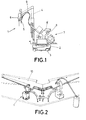
- Figure 1 shows an autonomous screwing robot (1) formed by an automated guided vehicle (2) provided with wheels (3) and a robotic arm (4) mounted in the automated guided vehicle (2), and an automated screwing device (5) and a vision system (6) both assembled with the robotic arm (4).
- a screws feeding system (7) is mounted in the automated guided vehicle (2), to automatically feeds screws to the screwing device (5).
- the screws feeding system (7) has at least one container (8) for the screws, a vibrator selector to ensure that the screws are positioned correctly, a tube (9) connected with the screwing device (5), and blowing system (not shown), such by means of a blowing system (not shown) screws are transported from the container (8) to the screwing device (5) in a manner already known in the prior art.
- the automated screwing device (5) is an electric device adapted to receive screws from the feeding system (7) and to screw them automatically.
- An interferometer is used to control screwing parameters, such as torque and turn angle.
- Figure 2 shows a horizontal tail plane (HTP) (10) to which some components like leading edges and trailing edge covers, are conventionally screwed.
- the robot (1) of the invention is programmed to move around the HTP, and bring the robotic arm (4) to several static working positions like the one shown in figure 1 , to perform screwing operations within its working range. Since the robotic arm cannot reach the entire working area of the HTP, the vehicle (2) moves the robotic arm (4) to several static positions around the HTP, so that only one robotic arm can reach the entire area of a piece to be screwed.
- HTP horizontal tail plane
- the robotic arm is a collaborative robot, which means that it is provided with security means so as it is capable to work safely in the same space than human operators, without need to be isolated.
- this is mounted with the robotic arm (4) in a proper position to capture images of a working area for the screwing device (5).
- the vision system (6) is associated with an images recognition system (not shown) in turn operatively communicated with the robotic arm (4), and adapted to identify target holes in the images captured by the vision system.
- the screwing device (5) is first positioned using a coordinates system to screw a hole in a known position in that coordinates system. Once the screwing device (5) is properly positioned, an images recognition system will identify holes inside an area for example of 50x50 mm2, and it would calculate hole parameters such as hole centre and the normal direction. Then, these parameters are used by the robotic arm, to perfectly align the axis of the screwing device with the axis of a target hole, to ensure the best performance of the operation.
- the screwing robot (1) has processing means to provide a report containing compliance data of the screwing process and the position of all the screws applied by the robot. That report, provides data such as: applied torque, number of turns, high of the screws head, etc., such as the processing means based on those parameters, can determine whether each screw has been correctly screwed or not.
Landscapes
- Engineering & Computer Science (AREA)
- Health & Medical Sciences (AREA)
- General Health & Medical Sciences (AREA)
- Orthopedic Medicine & Surgery (AREA)
- Robotics (AREA)
- Mechanical Engineering (AREA)
- Automatic Assembly (AREA)
- Manipulator (AREA)
Priority Applications (1)
| Application Number | Priority Date | Filing Date | Title |
|---|---|---|---|
| EP16382010.3A EP3192617A1 (fr) | 2016-01-12 | 2016-01-12 | Robot de vissage autonome |
Applications Claiming Priority (1)
| Application Number | Priority Date | Filing Date | Title |
|---|---|---|---|
| EP16382010.3A EP3192617A1 (fr) | 2016-01-12 | 2016-01-12 | Robot de vissage autonome |
Publications (1)
| Publication Number | Publication Date |
|---|---|
| EP3192617A1 true EP3192617A1 (fr) | 2017-07-19 |
Family
ID=55221371
Family Applications (1)
| Application Number | Title | Priority Date | Filing Date |
|---|---|---|---|
| EP16382010.3A Withdrawn EP3192617A1 (fr) | 2016-01-12 | 2016-01-12 | Robot de vissage autonome |
Country Status (1)
| Country | Link |
|---|---|
| EP (1) | EP3192617A1 (fr) |
Cited By (6)
| Publication number | Priority date | Publication date | Assignee | Title |
|---|---|---|---|---|
| DE102017120923A1 (de) | 2017-09-11 | 2019-03-14 | Airbus Operations Gmbh | Verbindungseinrichtung und Installationssystem |
| FR3078006A1 (fr) * | 2018-02-22 | 2019-08-23 | Psa Automobiles Sa | Station de montage d’un ouvrant sur une caisse de vehicule |
| DE102018129421A1 (de) * | 2018-11-22 | 2020-05-28 | Bayerische Motoren Werke Aktiengesellschaft | Vorrichtung zum Befestigen eines Bauteils an ein Strukturbauteil, insbesondere an ein Karosseriebauteil |
| CN114454165A (zh) * | 2022-01-27 | 2022-05-10 | 广州市斯睿特智能科技有限公司 | 一种基于视觉的汽车前端模块组装系统及方法 |
| WO2023272529A1 (fr) * | 2021-06-29 | 2023-01-05 | 西门子(中国)有限公司 | Procédé, appareil et système d'assemblage dynamique |
| CN116277046A (zh) * | 2022-12-05 | 2023-06-23 | 中国电力科学研究院有限公司 | 一种变压器运维取油机器人 |
Citations (7)
| Publication number | Priority date | Publication date | Assignee | Title |
|---|---|---|---|---|
| JPH05237729A (ja) * | 1992-02-28 | 1993-09-17 | Toshiba Corp | 自動ねじ締め装置 |
| US5570992A (en) * | 1954-07-28 | 1996-11-05 | Lemelson; Jerome H. | Free-traveling manipulator with optical feedback control and methods |
| US6098260A (en) * | 1996-12-13 | 2000-08-08 | Mcdonnell Douglas Corporation | Rivet fastening system for radial fuselage joints |
| DE10111979A1 (de) | 2001-03-13 | 2002-09-19 | Weber Schraubautomaten Gmbh | Schraubgerät |
| US20030208302A1 (en) * | 2002-05-01 | 2003-11-06 | Lemelson Jerome H. | Robotic manufacturing and assembly with relative radio positioning using radio based location determination |
| DE102012217474A1 (de) | 2012-09-26 | 2014-03-27 | Weber Schraubautomaten Gmbh | Handschraubvorrichtung mit abnehmbarem Griffteil |
| US20140135987A1 (en) | 2011-07-08 | 2014-05-15 | Johann Maischberger | Working device and method |
-
2016
- 2016-01-12 EP EP16382010.3A patent/EP3192617A1/fr not_active Withdrawn
Patent Citations (7)
| Publication number | Priority date | Publication date | Assignee | Title |
|---|---|---|---|---|
| US5570992A (en) * | 1954-07-28 | 1996-11-05 | Lemelson; Jerome H. | Free-traveling manipulator with optical feedback control and methods |
| JPH05237729A (ja) * | 1992-02-28 | 1993-09-17 | Toshiba Corp | 自動ねじ締め装置 |
| US6098260A (en) * | 1996-12-13 | 2000-08-08 | Mcdonnell Douglas Corporation | Rivet fastening system for radial fuselage joints |
| DE10111979A1 (de) | 2001-03-13 | 2002-09-19 | Weber Schraubautomaten Gmbh | Schraubgerät |
| US20030208302A1 (en) * | 2002-05-01 | 2003-11-06 | Lemelson Jerome H. | Robotic manufacturing and assembly with relative radio positioning using radio based location determination |
| US20140135987A1 (en) | 2011-07-08 | 2014-05-15 | Johann Maischberger | Working device and method |
| DE102012217474A1 (de) | 2012-09-26 | 2014-03-27 | Weber Schraubautomaten Gmbh | Handschraubvorrichtung mit abnehmbarem Griffteil |
Cited By (6)
| Publication number | Priority date | Publication date | Assignee | Title |
|---|---|---|---|---|
| DE102017120923A1 (de) | 2017-09-11 | 2019-03-14 | Airbus Operations Gmbh | Verbindungseinrichtung und Installationssystem |
| FR3078006A1 (fr) * | 2018-02-22 | 2019-08-23 | Psa Automobiles Sa | Station de montage d’un ouvrant sur une caisse de vehicule |
| DE102018129421A1 (de) * | 2018-11-22 | 2020-05-28 | Bayerische Motoren Werke Aktiengesellschaft | Vorrichtung zum Befestigen eines Bauteils an ein Strukturbauteil, insbesondere an ein Karosseriebauteil |
| WO2023272529A1 (fr) * | 2021-06-29 | 2023-01-05 | 西门子(中国)有限公司 | Procédé, appareil et système d'assemblage dynamique |
| CN114454165A (zh) * | 2022-01-27 | 2022-05-10 | 广州市斯睿特智能科技有限公司 | 一种基于视觉的汽车前端模块组装系统及方法 |
| CN116277046A (zh) * | 2022-12-05 | 2023-06-23 | 中国电力科学研究院有限公司 | 一种变压器运维取油机器人 |
Similar Documents
| Publication | Publication Date | Title |
|---|---|---|
| EP3192617A1 (fr) | Robot de vissage autonome | |
| JP6700055B2 (ja) | 自動化された動的製造システムおよび関連する方法 | |
| US10668616B2 (en) | Robot including telescopic assemblies for positioning an end effector | |
| EP2628565B1 (fr) | Dispositif de rivetage pour fuselage d'avion | |
| US10105853B1 (en) | Flexible robot end-effector for assembling door closure | |
| EP2947016B1 (fr) | Appareil, système et procédé pour supporter un ensemble aile | |
| US9452500B2 (en) | System and method for assembly manufacturing | |
| US8255070B2 (en) | Method and apparatus for establishing a camera focal length for installing fasteners | |
| CN113245594B (zh) | 用于对工件钻孔的方法和设备 | |
| JP2017043344A (ja) | ロボットシステム及びロボットシステムの操作方法 | |
| EP3560624B1 (fr) | Système et methode d'installation de fixation de décalage | |
| KR20150125571A (ko) | 항공기 구조물들에 대한 유연한 제조 시스템 | |
| US10435179B2 (en) | Camera assisted robotic system for locating the end of a fastener extending through an aircraft part during manufacture thereof | |
| EP3626362B1 (fr) | Procédé et appareil pour alimenter un collet de boulon serti | |
| EP3601041B1 (fr) | Système d'automatisation et procédé pour faire fonctionner un système d'automatisation | |
| CN101462595A (zh) | 一种基于工业机器人的飞机系统件安装方法及装置 | |
| WO2015097102A1 (fr) | Procédé de montage automatisé sur un poste de travail de montage, et poste de travail de montage automatisé associé | |
| WO2017001044A1 (fr) | Procédé pour positionner une pièce | |
| CA2716134A1 (fr) | Outil robotise pour le positionnement haute precision et la fixation de pieces de bois sur un mur prefabrique | |
| US20190039249A1 (en) | Multi-axis robot and method for controlling the same for painting objects | |
| JP6366665B2 (ja) | ロボット装置、組立装置、把持ハンド、および物品の製造方法 | |
| DE102022126199B4 (de) | Unterbetätigtes Fügesystem für sich bewegende Montagelinie | |
| US9815217B2 (en) | System and method for forming holes onto a sheet-metal assembly | |
| Caterino et al. | Robotized assembly and inspection of composite fuselage panels: The LABOR project approach | |
| CN108247616A (zh) | 一种工厂用陆空双用分类机器人 |
Legal Events
| Date | Code | Title | Description |
|---|---|---|---|
| PUAI | Public reference made under article 153(3) epc to a published international application that has entered the european phase |
Free format text: ORIGINAL CODE: 0009012 |
|
| STAA | Information on the status of an ep patent application or granted ep patent |
Free format text: STATUS: THE APPLICATION HAS BEEN PUBLISHED |
|
| AK | Designated contracting states |
Kind code of ref document: A1 Designated state(s): AL AT BE BG CH CY CZ DE DK EE ES FI FR GB GR HR HU IE IS IT LI LT LU LV MC MK MT NL NO PL PT RO RS SE SI SK SM TR |
|
| AX | Request for extension of the european patent |
Extension state: BA ME |
|
| STAA | Information on the status of an ep patent application or granted ep patent |
Free format text: STATUS: REQUEST FOR EXAMINATION WAS MADE |
|
| 17P | Request for examination filed |
Effective date: 20180105 |
|
| RBV | Designated contracting states (corrected) |
Designated state(s): AL AT BE BG CH CY CZ DE DK EE ES FI FR GB GR HR HU IE IS IT LI LT LU LV MC MK MT NL NO PL PT RO RS SE SI SK SM TR |
|
| STAA | Information on the status of an ep patent application or granted ep patent |
Free format text: STATUS: EXAMINATION IS IN PROGRESS |
|
| 17Q | First examination report despatched |
Effective date: 20190712 |
|
| STAA | Information on the status of an ep patent application or granted ep patent |
Free format text: STATUS: THE APPLICATION IS DEEMED TO BE WITHDRAWN |
|
| 18D | Application deemed to be withdrawn |
Effective date: 20191123 |