EP3193284A1 - Étiquette rfid - Google Patents
Étiquette rfid Download PDFInfo
- Publication number
- EP3193284A1 EP3193284A1 EP17156719.1A EP17156719A EP3193284A1 EP 3193284 A1 EP3193284 A1 EP 3193284A1 EP 17156719 A EP17156719 A EP 17156719A EP 3193284 A1 EP3193284 A1 EP 3193284A1
- Authority
- EP
- European Patent Office
- Prior art keywords
- rfid
- housing
- rfid tag
- receiving chamber
- metal frame
- Prior art date
- Legal status (The legal status is an assumption and is not a legal conclusion. Google has not performed a legal analysis and makes no representation as to the accuracy of the status listed.)
- Withdrawn
Links
Images


Classifications
-
- G—PHYSICS
- G06—COMPUTING OR CALCULATING; COUNTING
- G06K—GRAPHICAL DATA READING; PRESENTATION OF DATA; RECORD CARRIERS; HANDLING RECORD CARRIERS
- G06K19/00—Record carriers for use with machines and with at least a part designed to carry digital markings
- G06K19/06—Record carriers for use with machines and with at least a part designed to carry digital markings characterised by the kind of the digital marking, e.g. shape, nature, code
- G06K19/067—Record carriers with conductive marks, printed circuits or semiconductor circuit elements, e.g. credit or identity cards also with resonating or responding marks without active components
- G06K19/07—Record carriers with conductive marks, printed circuits or semiconductor circuit elements, e.g. credit or identity cards also with resonating or responding marks without active components with integrated circuit chips
- G06K19/077—Constructional details, e.g. mounting of circuits in the carrier
- G06K19/07749—Constructional details, e.g. mounting of circuits in the carrier the record carrier being capable of non-contact communication, e.g. constructional details of the antenna of a non-contact smart card
- G06K19/07758—Constructional details, e.g. mounting of circuits in the carrier the record carrier being capable of non-contact communication, e.g. constructional details of the antenna of a non-contact smart card arrangements for adhering the record carrier to further objects or living beings, functioning as an identification tag
-
- A—HUMAN NECESSITIES
- A61—MEDICAL OR VETERINARY SCIENCE; HYGIENE
- A61B—DIAGNOSIS; SURGERY; IDENTIFICATION
- A61B90/00—Instruments, implements or accessories specially adapted for surgery or diagnosis and not covered by any of the groups A61B1/00 - A61B50/00, e.g. for luxation treatment or for protecting wound edges
- A61B90/90—Identification means for patients or instruments, e.g. tags
-
- A—HUMAN NECESSITIES
- A61—MEDICAL OR VETERINARY SCIENCE; HYGIENE
- A61B—DIAGNOSIS; SURGERY; IDENTIFICATION
- A61B90/00—Instruments, implements or accessories specially adapted for surgery or diagnosis and not covered by any of the groups A61B1/00 - A61B50/00, e.g. for luxation treatment or for protecting wound edges
- A61B90/90—Identification means for patients or instruments, e.g. tags
- A61B90/98—Identification means for patients or instruments, e.g. tags using electromagnetic means, e.g. transponders
-
- G—PHYSICS
- G06—COMPUTING OR CALCULATING; COUNTING
- G06K—GRAPHICAL DATA READING; PRESENTATION OF DATA; RECORD CARRIERS; HANDLING RECORD CARRIERS
- G06K19/00—Record carriers for use with machines and with at least a part designed to carry digital markings
- G06K19/06—Record carriers for use with machines and with at least a part designed to carry digital markings characterised by the kind of the digital marking, e.g. shape, nature, code
- G06K19/067—Record carriers with conductive marks, printed circuits or semiconductor circuit elements, e.g. credit or identity cards also with resonating or responding marks without active components
- G06K19/07—Record carriers with conductive marks, printed circuits or semiconductor circuit elements, e.g. credit or identity cards also with resonating or responding marks without active components with integrated circuit chips
- G06K19/077—Constructional details, e.g. mounting of circuits in the carrier
- G06K19/07749—Constructional details, e.g. mounting of circuits in the carrier the record carrier being capable of non-contact communication, e.g. constructional details of the antenna of a non-contact smart card
- G06K19/07771—Constructional details, e.g. mounting of circuits in the carrier the record carrier being capable of non-contact communication, e.g. constructional details of the antenna of a non-contact smart card the record carrier comprising means for minimising adverse effects on the data communication capability of the record carrier, e.g. minimising Eddy currents induced in a proximate metal or otherwise electromagnetically interfering object
-
- A—HUMAN NECESSITIES
- A61—MEDICAL OR VETERINARY SCIENCE; HYGIENE
- A61B—DIAGNOSIS; SURGERY; IDENTIFICATION
- A61B17/00—Surgical instruments, devices or methods
- A61B17/28—Surgical forceps
- A61B17/2812—Surgical forceps with a single pivotal connection
-
- A—HUMAN NECESSITIES
- A61—MEDICAL OR VETERINARY SCIENCE; HYGIENE
- A61B—DIAGNOSIS; SURGERY; IDENTIFICATION
- A61B17/00—Surgical instruments, devices or methods
- A61B17/32—Surgical cutting instruments
- A61B17/3201—Scissors
-
- A—HUMAN NECESSITIES
- A61—MEDICAL OR VETERINARY SCIENCE; HYGIENE
- A61B—DIAGNOSIS; SURGERY; IDENTIFICATION
- A61B17/00—Surgical instruments, devices or methods
- A61B17/32—Surgical cutting instruments
- A61B17/3209—Incision instruments
- A61B17/3211—Surgical scalpels, knives; Accessories therefor
Definitions
- the invention relates to an RFID marking element for equipping surgical instruments, hereinafter referred to simply as tag.
- Conventional RFID tags for mounting surgical instruments comprise, in addition to a substantially annular metal frame, a disc-shaped plastic or ceramic body which is surrounded by the metal frame.
- the metal frame itself can be fixed to a tool to be equipped by welding, in particular laser welding.
- an RFID element is potted in a hole in the instrument.
- Instruments equipped with RFID tags reduce the risk of instruments remaining in the patient's body after surgery. Also, the instrument inventory is easier to manage and better understand the use of the surgical instruments during their lifetime.
- the RFID tags known under the SIMSAFE name use an annular metal frame with a slot in it to prevent a short circuit. Nevertheless, the transmission powers of the RFID tags are so equipped instruments are still too low for easy handling in everyday clinical practice.
- the object of the invention is to propose an RFID tag which is suitable for equipping surgical instruments and with which, in addition to a stable anchoring on the instrument, an encapsulation of the RFID elements in relation to the environment and a good cleanability, also an improved detectability, i. Transmission power in the environment of the instrument, can be achieved.
- a housing is provided in the RFID tags according to the invention, which is held only with a first end to the metal frame.
- the receiving chamber for the RFID element is spatially spaced in the housing from the first end thereof. This allows an arrangement of the RFID element with its antenna such that the antenna is spatially disposed substantially outside the metal frame.
- the antenna is preferably arranged in the housing such that there is a spatial distance to the metal frame.
- the RFID tags according to the invention enable a secure encapsulation of the RFID element, a good cleanability and, moreover, a positioning of the RFID element in the housing, which permits a substantially unhindered emission of the RFID element.
- the housing with its receiving chamber can be designed as a simple encapsulation, wherein the RFID element is cast into the housing material is. A separate manufacturing step for forming the receiving chamber is unnecessary in this embodiment.
- Preferred materials for the production of the housing or the encapsulation are plastic or ceramic materials.
- the RFID elements are preferably used in a previously manufactured receiving chamber of the housing and held there for example non-positively and / or positively or materially connected to the housing.
- a housing which is open on one side is provided as the housing, wherein the opening of the housing forms an access to the receiving chamber.
- the opening is designed so that the RFID tag can be easily inserted into the housing or its receiving chamber.
- the receiving chamber is preferably adapted in its cross section to the geometry of the RFID element that this can be engaged with a guide through the walls of the chamber in its final mounting position.
- the receiving chamber as a chamber open on one side can be closed with a closure element, wherein the closure element is preferably glued or welded to the housing, in particular welded by means of ultrasound.
- the first end of the housing comprises the opening forming the access to the receiving chamber.
- the metal frame can then be designed such that the first end, which comprises the opening forming the access to the receiving chamber, is completely accommodated there.
- a tight connection between the metal frame and the surgical instrument can be produced, so that the receiving chamber of the housing can remain open in the direction of the opening.
- the metal frame and its connection with the surgical Instrument provides adequate protection against environmental influences, especially when sterilizing the instruments.
- the RFID element is turned away with its antenna of the metal frame and / or arranged spatially spaced from this in the receiving chamber.
- connection between the housing and the metal frame can be realized in various variations.
- the housing is molded onto the metal frame. In this case, in particular plastic materials for the production of the housing in question.
- the metal frame can be molded onto the housing, in which case the housing is then preferably formed of ceramic material.
- the housing made of plastic or ceramic materials, on the metal frame non-positively and / or positively, in particular also be kept in the press-fit.
- the housing of the RFID tag has a substantially planar surface area, which has a predetermined orientation to the antenna of the RFID element, which is preferably selected to be approximately coplanar with the antenna plane of the RFID element.
- a predetermined orientation to the antenna of the RFID element which is preferably selected to be approximately coplanar with the antenna plane of the RFID element.
- the invention further relates to an instrument equipped with an RFID tag of the present invention.
- the metal mount of the RFID tag is welded to the instrument, laser welding in particular being preferred here.
- the instrument is populated with two or more RFID tags, the two or more RFID tags being arranged on the instrument such that the antennas of their respective RFID elements are aligned in different planes, the planes preferably form an angle of about 70 ° to about 110 ° with each other, preferably about 90 °.
- two RFID elements are arranged with a substantially orthogonal orientation of the antennas to each other in a common housing.
- a location-independent identification of the instrument can then take place with only one RFID tag.
- the RFID tags of the invention v.a. can also be used to advantage if conventional instruments that were not developed from the outset for fitting with RFID tags should be made identifiable and traceable via RFID tags.
- the RFID tags of the present invention are easy to manufacture with high tightness and safely attached to the instrument, with a good cleanability, a good function and a high flexibility in the choice of location for the placement of the instruments is given.
- FIG. 1 shows an RFID tag, generally designated by the numeral 10, of the present invention having an annular metal socket 12, a housing 14, and an RFID element 16 to be disposed in the housing.
- the housing 14 has a receiving chamber 18 in which the RFID element 16 is received.
- the housing 14 further has a truncated cone-shaped outer contour with a recessed at the lower truncated cone end edge 20, which can be inserted into the complementary shaped opening of the annular metal frame 12 in the press fit.
- the latter is possible if the housing 14 is made of plastic.
- the metal ring 12 can also be injection-molded onto the housing 14, which then consists, for example, of ceramic material.
- the first end of the housing 14 with the recessed edge 20 also has an opening 24, which provides access to the receiving chamber 18 of the housing 14.
- the receiving chamber 18 and the opening 24 of the housing 14 are adapted to the geometry of the RFID element 16 so that it can be guided and placed in a predetermined spatial orientation in the receiving chamber 18.
- the RFID element 16 is preferably inserted into the receiving chamber 18 so that its in Figure 1A Upside drawn antenna 22 is spatially spaced from the annular metal frame 12 in the mounted state of the RFID tag 10 and is arranged in particular away from the metal frame.
- the recessed edge 20 of the housing 14 forms the first end, with which this is held in the annular metal frame 12.
- the RFID element 16 is fastened in the receiving chamber 18 either positively and / or non-positively or cohesively by means of an adhesive, in particular an adhesive based on silicone material. Alternatively, it is also possible to inject the housing 14 made of plastic to the RFID element 16 in the mutual orientation shown.
- the first end of the housing 14 with its opening 24 may remain open in the assembled state of the RFID tag 10, since subsequently the RFID tag is held with the lower edge 26 of the annular metal frame 12 on a surgical instrument, preferably via a laser weld running all around so that the RFID element 16 is sufficiently protected against environmental influences.
- FIG. 1B shows a sectional view of the RFID tag 10 in the assembled state, to illustrate the assembly of the RFID tag 10 on a Instrument an instrument surface 28 is schematically shown with.
- FIG. 2A shows an exploded view of a second embodiment of an RFID tag 40 according to the invention with a rectangular here formed metal frame 42, a cross-sectionally parabolic shaped housing 44 and an RFID element 46th
- the housing 44 has a receiving chamber 48 which is open on one side and which is in turn adapted to the shape of the RFID element 46.
- the receiving chamber 48 which is open on one side, can be closed in a sealing manner by means of a closure or cover element 50, for example by gluing or welding, in particular with an adhesive made of a plastic material.
- the symmetry axis of the receiving chamber 48 is aligned perpendicular to the parabolic plane of the housing.
- the parabolic in cross section formed housing 44 has at its first end a pin-shaped projection 52 which engage in an opening 54 of the metal frame 42 and positively and / or non-positively or materially bonded, for example by means of a silicone material, fixed.
- the RFID element 46 is equipped with an antenna 56 which is arranged in the mounted state of the RFID element in the housing 44 spaced from the metal frame 42.
- FIG. 2B shows the RFID tag 40 according to the invention in the assembled state, wherein in the sectional drawing of FIG. 2B it can be seen that the lid or closure element 50 can be positively inserted into an opening 58 of the housing 44 due to the complementary formation of its edge region.
- the lid 50 and the housing welded, in particular by means of ultrasonic welding or gluing together.
- the RFID element 46 is completely encapsulated in the housing 44 and thus protected against environmental influences, in particular also during the sterilization of an instrument equipped therewith.
- FIG. 2B again clearly shows the spatial distance of the antenna 56 of the RFID element 46 of the metal frame 42, a prerequisite for the significantly improved transmission power of the RFID tag 40 according to the invention.
- FIG. 2C is a variant of the RFID tag 40 as RFID tag 60 shown with a metal frame 62, a housing 64 and a recorded in the housing 64 RFID element 66.
- the one-sided in the housing 64 existing opening 68 is still open, and a Lid member 70 is provided to close opening 68 and thereby encapsulate RFID element 66.
- Figure 2C further shows an adaptation of the housing 64 opposite surface 72 of the metal frame 62, which is concave, to be applied directly to a convex surface 74 of a surgical instrument then form-fitting and then connected, for example by means of laser welding.
- FIG. 3A shows a further embodiment of an RFID tag 80 according to the invention with a metal frame 82, a housing 84 and an RFID element 86 arranged in the housing.
- the housing 84 For receiving the RFID element 86, the housing 84, which is formed substantially cylindrical, a receiving chamber 88 which extends parallel to the cylinder axis of the housing 84.
- the housing 84 has an opening 90 that provides access to the receiving chamber 88 and over which the RFID element 86 in the receiving chamber 88 can be used.
- the RFID element 86 can be fixed in the receiving chamber 88, for example by gluing it in its position at the first end or the end opposite the opening 90, as in FIG FIGS. 3A and 3B shown.
- the antenna 92 of the RFID element 86 is kept spatially outside the metal frame 82 and clearly spaced therefrom, so that the transmission power of the RFID element 86 is not impaired.
- a substantially planar surface region 89 of the housing is oriented coplanar with respect to the position of the RFID element 86 with its antenna 92, so that the orientation of the antenna 92 can still be seen even in the closed state of the RFID tag 80.
- a recessed conical structural element 94 is arranged, which can engage in a corresponding formed as a blind hole recess 96 in the metal frame 82.
- a sealing member 98 is arranged, which is due to the conical structure of the free end 94 and the opening 96 of the metal frame 82, which is here a blind hole, is clamped, so that a sealing connection between the housing 84 and the metal frame 82 is formed.
- the RFID element 86 is sufficiently protected from environmental influences.
- the RFID tag 80 with its metal frame 82 can also be welded to an instrument and thus a corresponding instrument can be fitted.
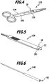
- FIG. 4 shows an example of an instrument in the form of a pair of scissors 110, the placement of a surgical instrument with the RFID tag 10 of the figure 1A.
- the RFID tag 10 is fixed in the region of the pivot connection of two branches 112, 114 of the instrument 110 by means of a laser weld 116. At the same time, this seals the receiving chamber of the RFID tag 10 tightly and thus protects the RFID element within the RFID tag 10 against environmental influences.
- FIG. 5 also shows the use of an RFID tag 10 fixed to a scalpel holder 120. Again, the RFID tag 10 was sealingly connected to its metal frame 12 via a circumferential laser weld 122 to the surface of the surgical instrument 120.
- FIG. 6 shows the attachment of an RFID tag 10 to a surgical instrument 140, which takes the form of a check mark. It can be seen here that the RFID tags of the present invention can be constructed very small and can also be fastened securely, ie sealingly, on very small surfaces.
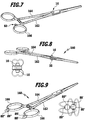
- FIG. 7 shows a clamp 160, in which on the one hand, an RFID tag 10 is welded in the region of the articulated connection of two branches 162, 164 on a flat surface.
- an RFID tag 10 is welded in the region of the articulated connection of two branches 162, 164 on a flat surface.
- a ring 166 at the proximal end of the handle industry 162 another RFID tag 60, as he associated with the Figure 2C arranged, which facilitates the detection of the instrument 116 supportive when this instrument is to be detected in a cluster with other instruments.
- FIG. 8 shows the terminal 160 of FIG. 7 , this time equipped with two RFID tags 10 on the top and bottom of the two handle industries 162, 164.
- the emission characteristic of the two RFID tags 10 is shown schematically in FIG FIG. 8 shown.
- the RFID tags can thus be read essentially independently of the position of the instrument.
- FIG. 9 Finally, the terminal 160 with two RFID tags 80 ', 80 ", as in the context of FIGS. 3A and 3B described, equipped.
- the radiation characteristic of the two RFID tags 80', 80" is in FIG. 9 shown schematically in addition. Here you can read out the RFID tags in any position or position of the instrument.
Landscapes
- Health & Medical Sciences (AREA)
- Engineering & Computer Science (AREA)
- Surgery (AREA)
- Life Sciences & Earth Sciences (AREA)
- Physics & Mathematics (AREA)
- Electromagnetism (AREA)
- Public Health (AREA)
- Nuclear Medicine, Radiotherapy & Molecular Imaging (AREA)
- Heart & Thoracic Surgery (AREA)
- Medical Informatics (AREA)
- Molecular Biology (AREA)
- Animal Behavior & Ethology (AREA)
- Biomedical Technology (AREA)
- General Health & Medical Sciences (AREA)
- Veterinary Medicine (AREA)
- Pathology (AREA)
- Oral & Maxillofacial Surgery (AREA)
- Computer Hardware Design (AREA)
- Microelectronics & Electronic Packaging (AREA)
- General Physics & Mathematics (AREA)
- Theoretical Computer Science (AREA)
- Surgical Instruments (AREA)
Applications Claiming Priority (2)
| Application Number | Priority Date | Filing Date | Title |
|---|---|---|---|
| DE102011052501A DE102011052501A1 (de) | 2011-08-08 | 2011-08-08 | RFID-Tag |
| EP12750722.6A EP2742465B2 (fr) | 2011-08-08 | 2012-08-06 | Étiquette rfid |
Related Parent Applications (2)
| Application Number | Title | Priority Date | Filing Date |
|---|---|---|---|
| EP12750722.6A Division-Into EP2742465B2 (fr) | 2011-08-08 | 2012-08-06 | Étiquette rfid |
| EP12750722.6A Division EP2742465B2 (fr) | 2011-08-08 | 2012-08-06 | Étiquette rfid |
Publications (1)
| Publication Number | Publication Date |
|---|---|
| EP3193284A1 true EP3193284A1 (fr) | 2017-07-19 |
Family
ID=46727179
Family Applications (2)
| Application Number | Title | Priority Date | Filing Date |
|---|---|---|---|
| EP12750722.6A Active EP2742465B2 (fr) | 2011-08-08 | 2012-08-06 | Étiquette rfid |
| EP17156719.1A Withdrawn EP3193284A1 (fr) | 2011-08-08 | 2012-08-06 | Étiquette rfid |
Family Applications Before (1)
| Application Number | Title | Priority Date | Filing Date |
|---|---|---|---|
| EP12750722.6A Active EP2742465B2 (fr) | 2011-08-08 | 2012-08-06 | Étiquette rfid |
Country Status (9)
| Country | Link |
|---|---|
| US (1) | US9033251B2 (fr) |
| EP (2) | EP2742465B2 (fr) |
| JP (1) | JP5781229B2 (fr) |
| CN (1) | CN103703475B (fr) |
| AU (1) | AU2012293680A1 (fr) |
| DE (1) | DE102011052501A1 (fr) |
| ES (1) | ES2632172T5 (fr) |
| RU (1) | RU2014103286A (fr) |
| WO (1) | WO2013020944A1 (fr) |
Cited By (3)
| Publication number | Priority date | Publication date | Assignee | Title |
|---|---|---|---|---|
| WO2021032782A1 (fr) | 2019-08-20 | 2021-02-25 | Aesculap Ag | Support d'étiquette rfid intégré |
| DE102020116932A1 (de) | 2020-06-26 | 2021-12-30 | Aesculap Ag | Medizinisches Instrument mit Transpondereinbaumodul und Medizinisches Transponderkommunikationssystem |
| WO2024061726A1 (fr) | 2022-09-23 | 2024-03-28 | Aesculap Ag | Instrument électrochirurgical ayant un transpondeur, système de communication par transpondeur et procédé de production |
Families Citing this family (38)
| Publication number | Priority date | Publication date | Assignee | Title |
|---|---|---|---|---|
| US8600478B2 (en) | 2007-02-19 | 2013-12-03 | Medtronic Navigation, Inc. | Automatic identification of instruments used with a surgical navigation system |
| US8233963B2 (en) | 2007-02-19 | 2012-07-31 | Medtronic Navigation, Inc. | Automatic identification of tracked surgical devices using an electromagnetic localization system |
| US8477076B1 (en) * | 2012-01-25 | 2013-07-02 | Clearcount Medical Solutions, Inc. | Antenna coupler mechanism |
| US9592101B2 (en) | 2012-09-24 | 2017-03-14 | Satyatek Sa | Radio frequency identification capsule (RFID) |
| JP2014174647A (ja) * | 2013-03-06 | 2014-09-22 | Krd Corporation Kk | Rfidタグ、保持部材、rfidタグを保持部材に装着したタグ装着体及びrfidタグの取付構造 |
| JP6201418B2 (ja) * | 2013-05-21 | 2017-09-27 | 凸版印刷株式会社 | Icタグ付き鋏状手動利器及びその製造方法 |
| CN104939872B (zh) * | 2014-03-31 | 2021-02-02 | 上海数斐信息科技有限公司 | 一种手术器械 |
| US9280738B2 (en) | 2014-05-04 | 2016-03-08 | Haldor Advanced Technologies Ltd | Identification tag and attachment |
| WO2015177490A1 (fr) * | 2014-05-23 | 2015-11-26 | Spa Track Medical Limited | Ensemble étiquette rfid |
| JP6542541B2 (ja) * | 2014-11-20 | 2019-07-10 | ケイ・アール・ディコーポレーション株式会社 | 作業用具 |
| GB201521814D0 (en) * | 2015-12-10 | 2016-01-27 | Cambridge Medical Robotics Ltd | Arm location |
| DE102015016233A1 (de) | 2015-12-16 | 2017-06-22 | Karl Storz Gmbh & Co. Kg | RFID-Transponder für ein medizinisches Instrument und/oder für ein Endoskop, medizinisches Instrument und/oder Endoskop sowie Montageverfahren |
| NL2016488B1 (en) * | 2016-03-24 | 2017-10-06 | Van Straten Medical B V | An RFID tag mounted or mountable on surgical or medical equipment or on a surgical or medical instrument. |
| CN109075526B (zh) * | 2016-04-18 | 2022-05-31 | 京瓷株式会社 | 发光元件收纳用构件及发光装置 |
| DE102016208541A1 (de) * | 2016-05-18 | 2017-11-23 | Olympus Winter & Ibe Gmbh | Chirurgisches Instrument, insbesondere elektrochirurgisches Instrument |
| WO2018088728A1 (fr) * | 2016-11-14 | 2018-05-17 | 재단법인 오송첨단의료산업진흥재단 | Système de détection de position utilisant la rfid et procédé de détection de position l'utilisant |
| NL2017833B1 (en) * | 2016-11-22 | 2018-05-28 | Van Straten Medical B V | An RFID tag mounted or mountable on surgical or medical equipment or on a surgical or medical instrument |
| US10517680B2 (en) * | 2017-04-28 | 2019-12-31 | Medtronic Navigation, Inc. | Automatic identification of instruments |
| CN109288601B (zh) * | 2017-07-24 | 2024-07-12 | 赛斐信息科技(南通)有限公司 | 射频标签安装组件、器械及安装方法 |
| DE102018113612A1 (de) | 2018-06-07 | 2019-12-12 | Gemü Gebr. Müller Apparatebau Gmbh & Co. Kommanditgesellschaft | Elektronisches Kennzeichen für eine metallische Komponente einer Anlage |
| WO2020018563A1 (fr) * | 2018-07-16 | 2020-01-23 | S.P.M. Flow Control, Inc. | Ensemble support-attache pour puce électronique servant à identifier et à gérer un équipement pétrolier et gazier |
| FR3084501A1 (fr) * | 2018-07-24 | 2020-01-31 | Optilook | Dispositif de porte radio etiquette universel pour montures de lunettes optiques aux fins d'eviter la pertubation des champs magnetiques pouvant etre introduite par la composition des montures |
| CA3113964A1 (fr) * | 2018-09-24 | 2020-04-02 | Stryker Corporation | Ensemble piece a main chirurgicale a ultrasons |
| DE102018125884A1 (de) * | 2018-10-18 | 2020-04-23 | Aesculap Ag | Werkzeug mit einer im Schaftbereich angeordneten Arbeitsendenbestimmungsvorrichtung |
| CN109576627A (zh) * | 2018-11-30 | 2019-04-05 | 赵宏达 | 基于热喷涂技术的表面标识和电子芯片植入封装方法 |
| EP3669814B1 (fr) * | 2018-12-20 | 2020-10-21 | W & H Dentalwerk Bürmoos GmbH | Instrument médical ou dentaire doté d'une étiquette mémoire rfid |
| CN109602478A (zh) * | 2019-02-12 | 2019-04-12 | 滕跃晖 | 新型医用工具及其制造方法 |
| SG10201906867RA (en) | 2019-07-25 | 2021-02-25 | Pci Private Ltd | Method for manufacturing electronic device |
| CA3155035C (fr) | 2019-10-29 | 2024-06-04 | William Alan BLAIR | Appareil pour faciliter le transfert d'echantillons biologiques stockes dans des conditions cryogeniques |
| US12354895B2 (en) * | 2019-12-19 | 2025-07-08 | Lam Research Corporation | Encapsulated RFID in consumable chamber parts |
| US11397884B2 (en) * | 2020-03-23 | 2022-07-26 | Fisher Controls International Llc | Brackets for amplifying antenna gain associated with mountable RFID tags |
| US11817187B2 (en) | 2020-05-18 | 2023-11-14 | TMRW Life Sciences, Inc. | Handling and tracking of biological specimens for cryogenic storage |
| JP7610303B2 (ja) | 2020-09-24 | 2025-01-08 | ティーエムアールダブリュ ライフサイエンシーズ,インコーポレイテツド | 極低温条件で保管された生物学的試料の移送を容易にするためのワークステーション及び装置 |
| USD963194S1 (en) | 2020-12-09 | 2022-09-06 | TMRW Life Sciences, Inc. | Cryogenic vial carrier |
| CA3200508A1 (fr) | 2020-12-10 | 2022-06-16 | TMRW Life Sciences, Inc. | Porte-echantillon dote d'un transpondeur sans fil pour fixation a un corps de collecte d'echantillon |
| DE102021107440A1 (de) * | 2021-03-24 | 2022-09-29 | Aesculap Ag | Integrierter RFID-Tag in einem Handinstrument |
| ES1278980Y (es) * | 2021-08-06 | 2022-01-11 | Pico Ignacio Guillem | Dispositivo de identificación reutilizable |
| EP4412453A4 (fr) | 2021-10-08 | 2025-01-22 | TMRW Life Sciences, Inc. | Systèmes, appareils et procédés de prélèvement et/ou de placement de contenants d'échantillon |
Citations (7)
| Publication number | Priority date | Publication date | Assignee | Title |
|---|---|---|---|---|
| US6121544A (en) * | 1998-01-15 | 2000-09-19 | Petsinger; Julie Ann | Electromagnetic shield to prevent surreptitious access to contactless smartcards |
| WO2006020377A2 (fr) * | 2004-07-23 | 2006-02-23 | Calypso Medical Technologies, Inc. | Fixation de marqueurs sans fil dans le corps humain |
| US20060084934A1 (en) * | 2004-10-18 | 2006-04-20 | Milton Frank | Transponder assembly and method for making same |
| EP1704893A1 (fr) * | 2005-03-21 | 2006-09-27 | Greatbatch-Sierra, Inc. | Système de détection et d'identification radio fréquence (RFID) pour des dispositifs médicaux implantables |
| WO2007125292A2 (fr) * | 2006-04-28 | 2007-11-08 | Obrist Closures Switzerland Gmbh | Fermeture avec dispositif rfid |
| WO2008112709A1 (fr) * | 2007-03-12 | 2008-09-18 | Rf Surgical Systems, Inc. | Logement et dispositif de transpondeur pour marquer des instruments |
| WO2010145651A2 (fr) * | 2009-06-16 | 2010-12-23 | Hegedues Viktor | Élément de marquage pour le marquage d'objets quelconques vivants ou non, objet pourvu d'un élément de marquage, système et procédé pour le marquage d'objets quelconques, en particulier pour la surveillance et la gestion d'objets |
Family Cites Families (24)
| Publication number | Priority date | Publication date | Assignee | Title |
|---|---|---|---|---|
| US5423334A (en) | 1993-02-01 | 1995-06-13 | C. R. Bard, Inc. | Implantable medical device characterization system |
| WO2000021031A1 (fr) * | 1998-10-06 | 2000-04-13 | Intermec Ip Corp. | Etiquette de systeme d'identification radiofrequence presentant un dipole sur une antenne a plan de sol |
| US6366206B1 (en) | 1999-06-02 | 2002-04-02 | Ball Semiconductor, Inc. | Method and apparatus for attaching tags to medical and non-medical devices |
| DE20012237U1 (de) | 1999-07-26 | 2000-10-12 | Karl Storz GmbH & Co. KG, 78532 Tuttlingen | Medizinisches Instrument mit einem berührungslos lesbaren Informationsträger |
| US6462661B2 (en) | 2000-11-20 | 2002-10-08 | Seagate Technology Llc | RF ID tag attachment to a disc drive |
| US7787958B2 (en) | 2001-04-13 | 2010-08-31 | Greatbatch Ltd. | RFID detection and identification system for implantable medical lead systems |
| US7126479B2 (en) * | 2004-08-17 | 2006-10-24 | Francis M. Claessens | Metal container closure having integral RFID tag |
| JP4247084B2 (ja) * | 2003-09-29 | 2009-04-02 | 川本産業株式会社 | 遺残事故防止システム |
| US7803307B2 (en) | 2004-06-07 | 2010-09-28 | Interplex Qlp, Inc. | Ultra high-temperature plastic package and method of manufacture |
| US7281311B2 (en) * | 2005-02-04 | 2007-10-16 | Diyar United Company | Method of attaching a transfer resistant RFID tag to a surface |
| US7275682B2 (en) | 2005-03-24 | 2007-10-02 | Varian, Inc. | Sample identification utilizing RFID tags |
| JP4870989B2 (ja) * | 2006-01-07 | 2012-02-08 | ケイ・アール・ディコーポレーション株式会社 | 作業用具及び作業用具のデータ記録装置 |
| CN101948025B (zh) * | 2006-02-22 | 2012-05-30 | 东洋制罐株式会社 | 带rfid标签的金属盖及使用其的金属物品 |
| US8461992B2 (en) * | 2006-05-12 | 2013-06-11 | Solstice Medical, Llc | RFID coupler for metallic implements |
| DE102006029122A1 (de) * | 2006-06-22 | 2007-12-27 | Amedo Gmbh | System zur Bestimmung der Position eines medizinischen Instrumentes |
| KR20100111665A (ko) | 2007-11-13 | 2010-10-15 | 빅토르 헤게뒤스 | 임의의 무생물체 또는 생물체를 마킹하는 방법 및 시스템, 및 특히 객체 통제와 객체 관리를 위해 임의의 객체들을 마킹하는 마킹 요소 및 그 용도 |
| ES2542863T3 (es) | 2008-02-12 | 2015-08-12 | Siemens Aktiengesellschaft | Marca de identificación para la identificación de objetos con superficie metálica |
| FR2930887A1 (fr) * | 2008-05-06 | 2009-11-13 | Ats Sferic Stellite S A S Soc | Instrument chirurgical invasif muni d'un transpondeur |
| US8054184B2 (en) * | 2008-07-31 | 2011-11-08 | Intuitive Surgical Operations, Inc. | Identification of surgical instrument attached to surgical robot |
| US8322955B2 (en) | 2009-05-14 | 2012-12-04 | Nordisk Aviation Products As | RFID adapter and RFID enabled cargo pallet |
| EP2423855B1 (fr) * | 2010-08-24 | 2012-10-03 | Siemens Aktiengesellschaft | Transpondeur RFID couplé inductif |
| US8444058B2 (en) * | 2011-01-20 | 2013-05-21 | Trovan, Ltd. | Embedded RFID tags and associated methods and systems |
| US8835285B2 (en) * | 2011-08-22 | 2014-09-16 | Flux Photon Corporation | Methods to fabricate vertically oriented anatase nanowire arrays on transparent conductive substrates and applications thereof |
| US9129201B2 (en) * | 2012-02-03 | 2015-09-08 | Checkpoint Systems, Inc. | Technology enhancement clip for hard tags |
-
2011
- 2011-08-08 DE DE102011052501A patent/DE102011052501A1/de not_active Withdrawn
-
2012
- 2012-08-06 EP EP12750722.6A patent/EP2742465B2/fr active Active
- 2012-08-06 RU RU2014103286/08A patent/RU2014103286A/ru not_active Application Discontinuation
- 2012-08-06 WO PCT/EP2012/065324 patent/WO2013020944A1/fr not_active Ceased
- 2012-08-06 CN CN201280036333.9A patent/CN103703475B/zh active Active
- 2012-08-06 AU AU2012293680A patent/AU2012293680A1/en not_active Abandoned
- 2012-08-06 ES ES12750722T patent/ES2632172T5/es active Active
- 2012-08-06 JP JP2014524352A patent/JP5781229B2/ja active Active
- 2012-08-06 EP EP17156719.1A patent/EP3193284A1/fr not_active Withdrawn
-
2013
- 2013-12-27 US US14/141,592 patent/US9033251B2/en active Active
Patent Citations (7)
| Publication number | Priority date | Publication date | Assignee | Title |
|---|---|---|---|---|
| US6121544A (en) * | 1998-01-15 | 2000-09-19 | Petsinger; Julie Ann | Electromagnetic shield to prevent surreptitious access to contactless smartcards |
| WO2006020377A2 (fr) * | 2004-07-23 | 2006-02-23 | Calypso Medical Technologies, Inc. | Fixation de marqueurs sans fil dans le corps humain |
| US20060084934A1 (en) * | 2004-10-18 | 2006-04-20 | Milton Frank | Transponder assembly and method for making same |
| EP1704893A1 (fr) * | 2005-03-21 | 2006-09-27 | Greatbatch-Sierra, Inc. | Système de détection et d'identification radio fréquence (RFID) pour des dispositifs médicaux implantables |
| WO2007125292A2 (fr) * | 2006-04-28 | 2007-11-08 | Obrist Closures Switzerland Gmbh | Fermeture avec dispositif rfid |
| WO2008112709A1 (fr) * | 2007-03-12 | 2008-09-18 | Rf Surgical Systems, Inc. | Logement et dispositif de transpondeur pour marquer des instruments |
| WO2010145651A2 (fr) * | 2009-06-16 | 2010-12-23 | Hegedues Viktor | Élément de marquage pour le marquage d'objets quelconques vivants ou non, objet pourvu d'un élément de marquage, système et procédé pour le marquage d'objets quelconques, en particulier pour la surveillance et la gestion d'objets |
Cited By (7)
| Publication number | Priority date | Publication date | Assignee | Title |
|---|---|---|---|---|
| WO2021032782A1 (fr) | 2019-08-20 | 2021-02-25 | Aesculap Ag | Support d'étiquette rfid intégré |
| US11903778B2 (en) | 2019-08-20 | 2024-02-20 | Aesculap Ag | Integrated RFID tag holder |
| DE102020116932A1 (de) | 2020-06-26 | 2021-12-30 | Aesculap Ag | Medizinisches Instrument mit Transpondereinbaumodul und Medizinisches Transponderkommunikationssystem |
| WO2021259894A1 (fr) | 2020-06-26 | 2021-12-30 | Aesculap Ag | Instrument médical équipé d'un module intégré de transpondeur et système de communication médical à transpondeur |
| US12197979B2 (en) | 2020-06-26 | 2025-01-14 | Aesculap Ag | Medical instrument having an installed transponder module, and medical transponder communication system |
| WO2024061726A1 (fr) | 2022-09-23 | 2024-03-28 | Aesculap Ag | Instrument électrochirurgical ayant un transpondeur, système de communication par transpondeur et procédé de production |
| DE102022124571A1 (de) | 2022-09-23 | 2024-03-28 | Aesculap Ag | Elektrochirurgisches Instrument mit Transponder, Transponderkommunikationssystem und Herstellungsverfahren |
Also Published As
| Publication number | Publication date |
|---|---|
| ES2632172T5 (es) | 2020-07-20 |
| US20140131454A1 (en) | 2014-05-15 |
| CN103703475B (zh) | 2016-09-21 |
| CN103703475A (zh) | 2014-04-02 |
| RU2014103286A (ru) | 2015-08-10 |
| US9033251B2 (en) | 2015-05-19 |
| ES2632172T3 (es) | 2017-09-11 |
| JP2014529782A (ja) | 2014-11-13 |
| EP2742465B2 (fr) | 2019-12-25 |
| DE102011052501A1 (de) | 2013-02-14 |
| EP2742465B1 (fr) | 2017-04-12 |
| EP2742465A1 (fr) | 2014-06-18 |
| AU2012293680A1 (en) | 2014-01-30 |
| WO2013020944A1 (fr) | 2013-02-14 |
| JP5781229B2 (ja) | 2015-09-16 |
Similar Documents
| Publication | Publication Date | Title |
|---|---|---|
| EP2742465B1 (fr) | Étiquette rfid | |
| DE60304063T2 (de) | Elektronische Ohrenmarke zur Markierung und Identifizierung von Vieh | |
| WO2021032782A1 (fr) | Support d'étiquette rfid intégré | |
| EP2519995B1 (fr) | Unité de radiofréquence en forme de paroi | |
| WO2008064758A1 (fr) | Circuit pour la répartition ou le regroupement de puissances à haute fréquence | |
| EP3569905B1 (fr) | Membrane de soupape, soupape à membrane ainsi que procédé de fixation d'un support de données logé dans un boîtier | |
| DE102020116932A1 (de) | Medizinisches Instrument mit Transpondereinbaumodul und Medizinisches Transponderkommunikationssystem | |
| EP2076908A1 (fr) | Traversee electrique, notamment pour des applications de pression, et procede de fabrication d'une telle traversee | |
| EP0186748A2 (fr) | Appareil auditif à porter dans l'oreille ou dans le canal auditif | |
| DE202011050941U1 (de) | RFID-Tag | |
| EP1356480B1 (fr) | Dispositif de commutation etanche | |
| WO1999030037A1 (fr) | Compresseur pour appareils frigorifiques a soupape amelioree | |
| EP3725250B1 (fr) | Instrument électrochirurgical pourvu d'un joint d'articulation étanché | |
| EP0407853A1 (fr) | Etiquette à attacher aux oreilles des animaux | |
| DE102007058426A1 (de) | Implantat | |
| EP2927553A1 (fr) | Raccordement, raccord et procédé de fabrication | |
| EP0819378B1 (fr) | Boítier de transpondeur implantable pour l'élevage animal | |
| DE102022124571A1 (de) | Elektrochirurgisches Instrument mit Transponder, Transponderkommunikationssystem und Herstellungsverfahren | |
| DE102009054220B4 (de) | Fluidsteuereinheit | |
| EP3610988B1 (fr) | Dispositif de pression à fixation à boulon centrée | |
| DE102018123545A1 (de) | Membran für ein Membranventil oder Stellventil mit einer Lasche und einem Transponder | |
| DE102011106553A1 (de) | Magnetspulenanordnung und Kollektion von Magnetspulenanordnungen | |
| EP0951261B1 (fr) | Dispositif d'equilibrage de pression servant de prothese d'une trompe d'eustache | |
| Pawlowski | Realitätsgerechte Zustandsbewertung gasisolierter Hochspannungsschaltanlagen | |
| DE10328695A1 (de) | Transponderanordnung und Gegenstand mit einer solchen Transponderanordnung |
Legal Events
| Date | Code | Title | Description |
|---|---|---|---|
| PUAI | Public reference made under article 153(3) epc to a published international application that has entered the european phase |
Free format text: ORIGINAL CODE: 0009012 |
|
| AC | Divisional application: reference to earlier application |
Ref document number: 2742465 Country of ref document: EP Kind code of ref document: P |
|
| AK | Designated contracting states |
Kind code of ref document: A1 Designated state(s): AL AT BE BG CH CY CZ DE DK EE ES FI FR GB GR HR HU IE IS IT LI LT LU LV MC MK MT NL NO PL PT RO RS SE SI SK SM TR |
|
| 17P | Request for examination filed |
Effective date: 20180115 |
|
| RBV | Designated contracting states (corrected) |
Designated state(s): AL AT BE BG CH CY CZ DE DK EE ES FI FR GB GR HR HU IE IS IT LI LT LU LV MC MK MT NL NO PL PT RO RS SE SI SK SM TR |
|
| 17Q | First examination report despatched |
Effective date: 20190613 |
|
| STAA | Information on the status of an ep patent application or granted ep patent |
Free format text: STATUS: THE APPLICATION IS DEEMED TO BE WITHDRAWN |
|
| 18D | Application deemed to be withdrawn |
Effective date: 20191024 |