EP3194113B1 - Wärmegrundebene auf basis von mikrosäulen - Google Patents
Wärmegrundebene auf basis von mikrosäulen Download PDFInfo
- Publication number
- EP3194113B1 EP3194113B1 EP15842101.6A EP15842101A EP3194113B1 EP 3194113 B1 EP3194113 B1 EP 3194113B1 EP 15842101 A EP15842101 A EP 15842101A EP 3194113 B1 EP3194113 B1 EP 3194113B1
- Authority
- EP
- European Patent Office
- Prior art keywords
- pillars
- copper
- mesh
- layer
- tgp
- Prior art date
- Legal status (The legal status is an assumption and is not a legal conclusion. Google has not performed a legal analysis and makes no representation as to the accuracy of the status listed.)
- Active
Links
Images








Classifications
-
- F—MECHANICAL ENGINEERING; LIGHTING; HEATING; WEAPONS; BLASTING
- F28—HEAT EXCHANGE IN GENERAL
- F28D—HEAT-EXCHANGE APPARATUS, NOT PROVIDED FOR IN ANOTHER SUBCLASS, IN WHICH THE HEAT-EXCHANGE MEDIA DO NOT COME INTO DIRECT CONTACT
- F28D15/00—Heat-exchange apparatus with the intermediate heat-transfer medium in closed tubes passing into or through the conduit walls ; Heat-exchange apparatus employing intermediate heat-transfer medium or bodies
- F28D15/02—Heat-exchange apparatus with the intermediate heat-transfer medium in closed tubes passing into or through the conduit walls ; Heat-exchange apparatus employing intermediate heat-transfer medium or bodies in which the medium condenses and evaporates, e.g. heat pipes
- F28D15/04—Heat-exchange apparatus with the intermediate heat-transfer medium in closed tubes passing into or through the conduit walls ; Heat-exchange apparatus employing intermediate heat-transfer medium or bodies in which the medium condenses and evaporates, e.g. heat pipes with tubes having a capillary structure
- F28D15/046—Heat-exchange apparatus with the intermediate heat-transfer medium in closed tubes passing into or through the conduit walls ; Heat-exchange apparatus employing intermediate heat-transfer medium or bodies in which the medium condenses and evaporates, e.g. heat pipes with tubes having a capillary structure characterised by the material or the construction of the capillary structure
-
- F—MECHANICAL ENGINEERING; LIGHTING; HEATING; WEAPONS; BLASTING
- F28—HEAT EXCHANGE IN GENERAL
- F28D—HEAT-EXCHANGE APPARATUS, NOT PROVIDED FOR IN ANOTHER SUBCLASS, IN WHICH THE HEAT-EXCHANGE MEDIA DO NOT COME INTO DIRECT CONTACT
- F28D15/00—Heat-exchange apparatus with the intermediate heat-transfer medium in closed tubes passing into or through the conduit walls ; Heat-exchange apparatus employing intermediate heat-transfer medium or bodies
- F28D15/02—Heat-exchange apparatus with the intermediate heat-transfer medium in closed tubes passing into or through the conduit walls ; Heat-exchange apparatus employing intermediate heat-transfer medium or bodies in which the medium condenses and evaporates, e.g. heat pipes
- F28D15/0233—Heat-exchange apparatus with the intermediate heat-transfer medium in closed tubes passing into or through the conduit walls ; Heat-exchange apparatus employing intermediate heat-transfer medium or bodies in which the medium condenses and evaporates, e.g. heat pipes the conduits having a particular shape, e.g. non-circular cross-section, annular
-
- F—MECHANICAL ENGINEERING; LIGHTING; HEATING; WEAPONS; BLASTING
- F28—HEAT EXCHANGE IN GENERAL
- F28F—DETAILS OF HEAT-EXCHANGE AND HEAT-TRANSFER APPARATUS, OF GENERAL APPLICATION
- F28F21/00—Constructions of heat-exchange apparatus characterised by the selection of particular materials
- F28F21/08—Constructions of heat-exchange apparatus characterised by the selection of particular materials of metal
- F28F21/081—Heat exchange elements made from metals or metal alloys
- F28F21/085—Heat exchange elements made from metals or metal alloys from copper or copper alloys
-
- G—PHYSICS
- G06—COMPUTING OR CALCULATING; COUNTING
- G06F—ELECTRIC DIGITAL DATA PROCESSING
- G06F1/00—Details not covered by groups G06F3/00 - G06F13/00 and G06F21/00
- G06F1/16—Constructional details or arrangements
- G06F1/20—Cooling means
- G06F1/203—Cooling means for portable computers, e.g. for laptops
-
- H—ELECTRICITY
- H10—SEMICONDUCTOR DEVICES; ELECTRIC SOLID-STATE DEVICES NOT OTHERWISE PROVIDED FOR
- H10W—GENERIC PACKAGES, INTERCONNECTIONS, CONNECTORS OR OTHER CONSTRUCTIONAL DETAILS OF DEVICES COVERED BY CLASS H10
- H10W40/00—Arrangements for thermal protection or thermal control
- H10W40/70—Fillings or auxiliary members in containers or in encapsulations for thermal protection or control
- H10W40/73—Fillings or auxiliary members in containers or in encapsulations for thermal protection or control for cooling by change of state
-
- F—MECHANICAL ENGINEERING; LIGHTING; HEATING; WEAPONS; BLASTING
- F28—HEAT EXCHANGE IN GENERAL
- F28F—DETAILS OF HEAT-EXCHANGE AND HEAT-TRANSFER APPARATUS, OF GENERAL APPLICATION
- F28F2225/00—Reinforcing means
-
- F—MECHANICAL ENGINEERING; LIGHTING; HEATING; WEAPONS; BLASTING
- F28—HEAT EXCHANGE IN GENERAL
- F28F—DETAILS OF HEAT-EXCHANGE AND HEAT-TRANSFER APPARATUS, OF GENERAL APPLICATION
- F28F2240/00—Spacing means
-
- F—MECHANICAL ENGINEERING; LIGHTING; HEATING; WEAPONS; BLASTING
- F28—HEAT EXCHANGE IN GENERAL
- F28F—DETAILS OF HEAT-EXCHANGE AND HEAT-TRANSFER APPARATUS, OF GENERAL APPLICATION
- F28F2245/00—Coatings; Surface treatments
- F28F2245/02—Coatings; Surface treatments hydrophilic
-
- F—MECHANICAL ENGINEERING; LIGHTING; HEATING; WEAPONS; BLASTING
- F28—HEAT EXCHANGE IN GENERAL
- F28F—DETAILS OF HEAT-EXCHANGE AND HEAT-TRANSFER APPARATUS, OF GENERAL APPLICATION
- F28F2245/00—Coatings; Surface treatments
- F28F2245/04—Coatings; Surface treatments hydrophobic
-
- H—ELECTRICITY
- H05—ELECTRIC TECHNIQUES NOT OTHERWISE PROVIDED FOR
- H05K—PRINTED CIRCUITS; CASINGS OR CONSTRUCTIONAL DETAILS OF ELECTRIC APPARATUS; MANUFACTURE OF ASSEMBLAGES OF ELECTRICAL COMPONENTS
- H05K7/00—Constructional details common to different types of electric apparatus
- H05K7/20—Modifications to facilitate cooling, ventilating, or heating
- H05K7/2029—Modifications to facilitate cooling, ventilating, or heating using a liquid coolant with phase change in electronic enclosures
- H05K7/20336—Heat pipes, e.g. wicks or capillary pumps
Definitions
- US 2011/0017431 A1 describes a flexible thermal ground plane including an evaporator region and a condenser region having a micro-wicking structure and a nano-wicking structure coupled with micro-wicking structure.
- a micromesh may be coupled with the micro-wicking structure.
- a thermal ground plane comprising a bottom layer configured to enclose a working fluid, wherein the bottom layer has a thickness less than 60 microns; a top layer configured to enclose the working fluid, wherein a perimeter of the bottom layer and a perimeter of the top layer are hermetically sealed together by thermo-compression bonding, wherein the top layer has a thickness less than 60 microns, wherein the top layer consists essentially of a metal; a first plurality of pillars disposed on an interior surface of the first planar substrate; a mesh layer disposed on the top of the first plurality of pillars and bonded with the top of the first plurality of pillars, wherein the mesh layer consists essentially of copper, or polymer encapsulated with copper, or stainless steel encapsulated with copper; and a second plurality of pillars disposed on an interior surface of the top layer within an area defined by the perimeter of the top layer and the second plurality of pillars
- the TGP may include a first planar substrate member configured to enclose a working fluid; a second planar substrate member configured to enclose the working fluid, wherein the first planar substrate member and the second planar substrate member are hermitically sealed together; a plurality of wicking structures disposed on the first planar substrate member; and a plurality of pillars disposed on an interior surface of the second planar substrate member, wherein the thermal ground plane has a thickness less than 300 microns.
- the plurality of wicking structures comprise a plurality of pillars disposed on the first planar substrate member and the plurality of wicking structures comprise a plurality of pillars formed on the second planar substrate member.
- the first planar substrate member and/or the second planar substrate member comprise at least one of a metallic layer, a copper-cladded polymer layer with thermal vias, a copper-cladded polymer layer without thermal vias, a polymer-coated copper layer, a metallic layer encapsulated by a hydrophilic coating, a copper metallic layer encapsulated by a hydrophilic hydrophobic coating, and/or a polymer layer encapsulated by a metallic layer.
- the first planar substrate member (e.g., a metal cladding layer) and/or the second planar substrate member may be thicker in one or more regions such as, for example, regions near the evaporator or the condenser.
- the plurality of wicking structures comprise a plurality of copper pillars bonded with a mesh layer.
- the a plurality of wicking structures may comprise a material with at least one property selected from the list consisting of copper mesh, stainless steel mesh, metal mesh, polymer mesh, copper-encapsulated mesh, a mesh encapsulated by a hydrophilic coating, a mesh encapsulated by a hydrophobic coating, a copper-encapsulated stainless steel mesh, and a mesh encapsulated by a hermetic seal.
- the plurality of wicking structures comprise copper pillars in contact with a stainless steel mesh encapsulated by copper or a copper mesh.
- the one or more planar spacers comprise copper pillars bonded with a stainless steel mesh encapsulated by copper or a copper mesh.
- the one or more planar spacers comprise a plurality of copper pillars or channels.
- the plurality of pillars comprises a plurality of pillars or channels with various star-shaped cross sections, such as rectangular, circular, and/or star-shaped.
- the plurality of wicking structures comprise polymer pillars hermetically sealed by copper or other coatings, and/or coated with a hydrophilic coating or a hydrophobic coating.
- the plurality of wicking structures comprise a mesh layer.
- the mesh layer may include a mesh selected from the list consisting of copper mesh, stainless steel mesh, metal mesh, polymer mesh and copper-encapsulated mesh stainless steel.
- the mesh layer for example, may include a hydrophilic coating or a hydrophobic coating or hermetic coating.
- the plurality of wicking structures and/or the plurality of pillars are deposited using a lithographic patterning process.
- the claimed invention comprises a hermetic seal by thermo-compression bonding.
- the hermetical seal can include a seal selected from the list consisting of a copper-silver sintered interface, a tin/lead solder, and a lead-free solder alloy.
- the TGP may include a top layer; a mesh layer comprising a plurality of arteries formed along a length of the mesh layer; and a bottom layer comprising a plurality of pillars that extend into the plurality of arteries/.
- the bottom layer and the top layer are hermetically sealed around their perimeter.
- Each of the plurality of pillars may have at least one dimension that is less than a dimension of at least one of the plurality of arteries.
- the plurality of arteries may be cut from the mesh layer.
- the TGP may include a micro-wick layer disposed on the bottom layer.
- the TGP may include a plurality of pillars disposed on the top layer.
- the skin temperature is the temperature of an exterior portion of a device (e.g., the case) that is touched by fingers, hands, face, ears, or any other part of a human body.
- a user would consider the temperature of the device to be hot.
- this perception of heat is dependent on the materials and the duration of the contact; it also varies from one person to another one due to their difference in thermal physiology.
- Figure 1 illustrates a graph of acceptable skin temperatures for a number of different materials considering different touch duration.
- a hot spot or region with a much higher temperature than other locations on a smart phone could be generated by an electronic chip such as, for example, a 5-Watt processor or a 1-Watt, small-size wireless amplifier. These hot spots or regions could be removed by effective heat spreading since the temperatures in the area outside these hot spots can be much lower.
- a metal heat spreader such as, for example, an aluminum or copper heat spreader
- the thickness of the metal heat spreader is being reduced in order to meet the demand for the reduction of the total system's thickness. For most mobile systems, a thinner configuration is usually desirable.
- a thin metal heat spreader With a thin metal heat spreader, its thermal resistance increases since it is affected by the thermal conductivity and cross-section area for heat conduction.
- Alternative approaches can use high thermal conductivity graphite heat spreaders.
- the thermal conductivity of graphite heat spreaders generally decreases with the thickness of the graphite layer.
- the high thermal conductivity graphite e.g., thermal conductivity of 1,500 W/mK, is too thin, e.g., 0.017 mm, to be effective to transfer heat over a large area.
- a TGP thin thermal ground plane
- a TGP may use phase-change heat transfer mechanisms with an evaporation-vapor transport-condensation-liquid return path for heat transfer.
- a TGP may be a very good heat spreader with effective thermal conductivities higher than that of a copper (see Figure 5 ).
- a TGP may include components and/or may be manufactured with processes described in US Patent Application No. 12/719,775 , entitled "Flexible Thermal Ground Plane and Manufacturing the Same.”
- Embodiments may also include a top layer including a plurality of spacers (or pillars) sealed with a bottom layer having a plurality of pillars.
- the spacers may be deposited on the top layer using a lithographic patterning process. In some embodiments, the pillars may be deposited on the bottom layer using a lithographic patterning process. In some embodiments, the pillars and spacers may be bonded or scribed on the first and/or second planar substrate. In some embodiments, the pillars may have a diameter that is less than or greater than the diameter of the pillars and/or spacers. In some embodiments, the spacers pillars may have a spacing that is less than or greater than the spacing diameter of the pillars. In some embodiments, the pillars in the spacers may have a height, diameter or spacing that is less than or greater than the spacing of the pillars in the wicking structure.
- FIG. 3 illustrates a diagram of an example TGP 300 according to some embodiments.
- the TGP 300 includes a top layer 310, a bottom layer 315, a liquid channel 320, and/or a vapor core 325.
- the TGP 300 may operate with evaporation, vapor transport, condensation, and/or liquid return of water or other cooling media for heat transfer between the evaporation region 330 and the condensation region 335.
- the top layer 310 may include copper, polyimide, polymer-coated copper, copper-cladded Kapton, etc.
- the top bottom layer 315 may include copper, polyimide, polymer-coated copper, copper-cladded Kapton, etc.
- the top layer 310 and the bottom layer 315 of the TGP is sealed together using thermo-pressure compression
- the liquid channel 320 may include copper mesh, stainless-steel mesh, or meshes made of other materials but encapsulated with copper.
- the liquid channel 320 may include one, two, three, four, five, six or more layers of mesh of the same or different materials.
- the liquid channel 320 may be bonded and/or sealed using FEP (fluorinated ethylene propylene), electroplating, sintering, and/ or other adhesives or sealants with the top layer 310.
- FEP fluorinated ethylene propylene
- atomic layer deposition of Al 2 O 3 , TiO 2 , SiO 2 , or other coatings may be used to encapsulate meshes of the liquid channel 320 with desirable functionality.
- the vapor core 325 includes a plurality of pillars disposed on the top layer 310.
- the pillars may be deposited using any type of deposition technique such as, for example, vapor deposition, etc.
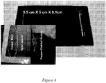
- the TGPs may include may an active region of various sizes, for example, the TGP may have at least one dimension (e.g., length, width, radius, diameter, etc.) that is less than 2 cm, 5 cm, 10 cm, 20 cm, 50 cm, 100 cm, 500 cm, 1000 cm, etc. and/or a thickness less than 0.1 mm, 0.25 mm, 2. 0.3 mm. .
- the active region may have dimensions of 9.5 cm X 5 cm X 0.1 cm.
- a TGP may include a copper-cladded Kapton bottom layer and a copper-cladded Kapton top layer with a copper or metallic mesh and/or a polymer spacer sandwiched in between.
- the metallic mesh may be copper mesh, stainless-steel mesh with or without a copper coating, or meshes made of other materials but encapsulated with copper.
- the copper mesh layer may include one, two, three, four, five, six or more layers of mesh.
- portions of the TGP e.g., the copper mesh and/or the polymer spacer
- FEP fluorinated ethylene propylene
- atomic layer deposition of Al 2 O 3 , TiO 2 , SiO 2 , or other coatings may be used to encapsulate the meshes with desirable functionality.
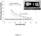
- Figure 5 illustrates the thermal resistance from the evaporator evaporation region to the condensation region of a TGP manufactured according to some embodiments.
- the TGP includes is characterized with a 1 inch by 1 inch (25,4 mm by 25,4 mm) heater injecting the heat to the TGP and a 1 inch by 1 inch 2. (25,4 mm by 25,4 mm) heat sink extracting the heat from the TGP.
- the active region of the test sample is about 200 mm X 50 mm X 1 mm. The results are compared with those obtained for a copper reference sample with the same dimensions.
- the TGP may include a layer having a plurality of pillars manufactured with electroplating processes that produces, for example, large bonding pads with copper-nickel-gold layers. Additionally or alternatively, in some embodiments, an ALD hydrophilic or hydrophobic coating process may be used to change the wettability of the pillars.
- the thermal resistances of a TGP manufactured according to embodiments are compared with those of a copper reference sample with the same dimensions.
- the thermal resistance from the evaporator to the condenser is a function of input power of the heater.
- the thermal resistance drops from 7 K/W to about 2 K/W when the power increases from 5 to 25 Watts.
- the corresponding thermal resistance of the copper sample is about 10 K/W.
- the effective thermal conductivity of the TGP reaches about 2,000 W/mK at 25 Watts since its resistance is about 1/5 of the copper with the thermal conductivity of 400 W/mK.
- our customer ran the power all the way to 35 Watts and reached the effective thermal conductivities up to 4,000 to 7,000 W/mK.
- thermal vias with higher thermal conductivity than the substrate materials may be used.
- thermal vias were not used in this sample which was used to create generate the illustration results shown in the graph in Figure 5 ; therefore, there is a relatively large and undesirable thermal resistance across the 50- um thick Kapton layer due to the low thermal conductivity of Kapton.
- the total thermal resistance of the TGP may increase with an effective thermal conductivity over 3,000 W/mK even at the 25-Watt power level.
- Figure 6 illustrates a TGP 600 according to some embodiments.
- the top layer 310 and/or the bottom layer 315 may include copper cladded Kapton and/or may be similar to the top layer 310 and the bottom layer 315 described above in conjunction with Figure 3 .
- the top layer 310 and the bottom layer 315 of the TGP 600 is sealed together using thermo-pressure compression.
- the TGP 600 includes a liquid channel, a wicking structure, and/or a vapor core.
- the wicking structure 610 may include a copper mesh, stainless-steel mesh with or without a copper coating, or one or more mesh made of other materials but encapsulated with copper.
- the wicking structure 610 may include one, two, three, four, five, six or more layers of mesh of the same or different material.
- the wicking structure 610 may be bonded and/or sealed using FEP (fluorinated ethylene propylene) electroplating, sintering, and/or other adhesives or sealants with the top layer 310.
- FEP fluorinated ethylene propylene
- atomic layer deposition of Al 2 O 3 , TiO 2 , SiO 2 , or other coatings may be used to encapsulate meshes of the liquid channel 615 with desirable functionality.
- ALD atomic layer deposition
- TiO 2 TiO 2
- SiO 2 SiO 2
- other coatings may be used to encapsulate meshes of the liquid channel 615 with desirable functionality.
- the wicking structure 610 is bonded with or on a plurality of pillars of the liquid channel 615.
- the wicking structure 610 may include a woven mesh that may be bonded to the pillars of the liquid channel 615 and/or the vapor core 605 through an electroplating process.
- the mesh may be a copper woven mesh or a metallic mesh.
- the wicking structure 610 (e.g., woven mesh) may be encapsulated by copper.
- the top layer 310 with the vapor core 605 and the bottom layer 315 with the liquid channel 615 may be sealed together with the wicking structure 610 with a mesh in between.
- the TGP 600 may be charged with a working fluid, such as water, methane, ammonia, or other coolants or refrigerants that are compatible with the surfaces exposed to the working fluid.
- the liquid channel 615 includes a plurality of pillars (e.g., electroplated pillars).
- the pillars in the vapor core 605 may have at least one dimension (e.g., height, width, length, diameter, etc.) that is smaller than at least one dimension (e.g., height, width, length, diameter, etc.) of the pillars of the liquid channel 615.
- a photo-lithographic patterning process may be used to fabricate the pillars in the liquid channel 615 and/or the vapor core 605.
- a photolithography process may be used to form a plurality of pillars on the top layer 310 to form the vapor core 605 and/or a photo-lithographic patterning process may be used to form a plurality of pillars on the bottom layer 315 to form the liquid channel 615.
- the photo-lithographic patterning process may control the positioning and/or the heights of the pillars with a resolution of a few microns.
- the plurality of pillars on the top layer 310 and/or on the bottom layer 315 may be formed by the mechanical scribing process.
- the thickness of a TGP may be less than about 300, 250, 200, 150, or 100 microns.
- the top layer 310 and/or the bottom layer 315 may be 10, 20, 30, 40, 50, but less than 60 microns thick
- the liquid channel e.g., liquid channel 615)
- the wicking structure e.g., wicking structure 610
- the vapor core e.g., vapor core 605
- the vapor core e.g., vapor core 605 may be 10, 20, 30, 40, 50, 75, 100, 125, 150, etc. microns thick.
- Figure 7 shows an example of a TGP 600 with a top layer 310 having pillars formed thereon to form the vapor core 605, a bottom layer 315 having pillars formed thereon to form the liquid channel 615 and a wicking structure 610 disposed in between according to some embodiments.
- the pillars may be fabricated using electroplating over photo-lithograpy-defined openings.
- TGPs manufactured according to some embodiments may have a thickness larger than or less than 0.25 mm as shown in Figure 8 . The total thickness can be reduced further since all dimensions of critical features are defined by the photo-lithography processes. In some embodiments, TGPs may have a thickness less than about 0.25, 0.2, 0.15, 0.1, 0.05 mm, etc.
- the pillars of the liquid channel 615 and/or the vapor core 605 may allow the TGP to remain effective under different mechanical loadings even in an extremely thin configuration.
- Figure 9 illustrates an example TGP with a plurality of electroplated pillars and mesh according to some embodiments.
- the pillars on the top layer and/or the bottom layer may be fabricated using a photo-lithographic patterning process and/or may have any dimension such as, for example, 100 um x 100 um squares with 60 um spacing in between each square. This spacing, however, does not fall under the claimed invention.
- These pillars may be bonded to a stainless steel woven mesh (e.g., having 500 wires/ inch (19.7 wires/mm), 50 um thick) through various bonding techniques such as, for example, copper electroplating.
- the mesh for example, may also be at least partially or completely encapsulated by electroplated copper.
- the combined mesh-pillar structure may achieve low capillary radius (or high pumping pressure) in the evaporation regions and higher flow hydraulic radius (or low flow pressure drop) in the fluid channel.
- a controlled over-plating process may be used to form the pillars with rounded heads.
- this shape may be beneficial, for example, to form a sharp angle of each interface between a pillar and the mesh bonded. These sharp angles, for example, may enhance the capillary p umping force pulling the liquid returned from the condenser to the evaporator.
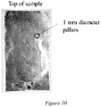
- Figure 10 shows an example top layer with copper pillars electroplated through a photolithography-defined opening according to some embodiments.
- the height of the pillars is 100 microns
- the diameter (or width) of the pillars is 1 mm
- the spacing between the pillars is 2 mm.
- the pillars may define the gap of the vapor core.
- large spacing e.g., a spacing between pillars that is greater than the diameter of the individual pillars or a spacing between pillars that is greater than or equal to twice the diameter of the individual pillars
- the flow resistance may be reasonably low, so that, according to the invention, the spacing between the pillars of the second plurality of pillars is larger than two times the diameter of each pillar.
- the pillars formed on the top layer and/or on the bottom layer may be hydrophilic.
- the pillars may have a cross section that is round; oval; polygonal; star shaped as shown, for example, in Figure 6 ; hexagonal; octagonal; pentagonal; square; rectangular; triangular; etc.
- condensation of vapor can occur along the vapor core.
- the hydrophilic property of the pillars in the vapor core can reduce the size of vapor droplets or bubbles.
- the star-shaped pillars can further enhance the hydrophilic properties or wettability.
- the pillars may be constructed from material other than copper.
- the pillars may be manufactured from polymer using photo-lithographic deposition and etching techniques. Such polymer pillars, for example, can be baked, followed by hermetic encapsulation with copper, ALD moisture barrier coating or other sealing materials. In some embodiments, the thermal conductivities of polymer pillars may be much lower than that of copper.
- the process of manufacturing a TGP may include a removing air out of the TGP followed by charging the TGP with water or other working fluid that is compatible with an exposed TGP inner surface.
- a small diameter copper tube may be coupled with the TGP to allow for vacuuming and/or charging. After water charging, for example, this tube can be pinch-sealed. In some embodiments, the pinch-sealed tube can be removed by an additional seal separating the active region from the region with the tube.
- Figure 11 shows an experimental setup that can be used to characterize the properties of a thin flexible TGP according to some embodiments.
- the evaporator (e.g., heater) region was defined by the heater size was of 8 mm x 8 mm and the condensation region was defined by the condenser block was with an area of 5 cm x 2.5 cm.
- the temperature difference between the evaporator evaporation region and the condenser condensation region was measured, and this difference per unit of heat transferred to the condenser heater's input power was used to calculate considered the thermal resistance.
- the entire setup was covered by thermal insulation to reduce air natural convection effect by air.
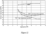
- FIG 12 is a graph showing the thermal resistances as a function of heater's input power of a TGP manufactured according to some embodiments and using the experimental setups shown in Figure 11 .
- TGPs manufactures manufactured according to embodiments outperform copper. From these results, the thin TGP's, effective thermal conductivity may be between 500 and 5,000 W/mK or 1,000 and 1,500 W/mK.
- the location of heat extraction condensation may affect a TGP's performance.
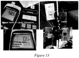
- Figure 13 shows an experimental setup that can be used to characterize the properties of a thin flexible TGP with distributed condensers condensation cooled by air nature air convection without an active cooling heat sink according to some embodiments.
- TGP 400 may be constructed with any of the following configurations.
- the material on the interior surface exposed to water may be copper.
- a stainless steel mesh 405 may be used that is encapsulated by copper.
- a copper mesh can be used.
- the spacer 420 for the vapor core may be defined by a polymer mesh such as, for example, a nylon mesh or a PEEK mesh in conjunction with or in addition to copper pillars.
- the spacer 420 may be a copper mesh.
- one or more copper cladded Kapton layers 410 and 420 may be included.
- a wicking layer 405 may be included.
- One or more layers may be combined and/or bonded together.
- FIG 14B shows an example TGP according to some embodiments.
- a plurality of meshes e.g., a copper mesh and a nylon/peek spacer
- the bottom layer and/or the top layer may be assembled and/or sealed with one or more sealing techniques such as, for example, ultrasound welding, laser welding, between two layers and/or with a solder seal to form a high-yield hermetic seal.
- sealing techniques such as, for example, ultrasound welding, laser welding, between two layers and/or with a solder seal to form a high-yield hermetic seal.
- Any other technique may be used to hermetically seal the TGP such as, for example, photolithography-defined solder masking, copper-to-copper seam welding including ultrasonic welding or laser welding, copper-silver sintering, solder dipping, etc.
- a first seal 455 and a second seal 455 may be used. All these sealing techniques do not fall under the claimed invention, which comprises a thermo-compression bonding.
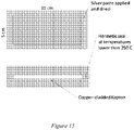
- FIG. 15 illustrates another example TGP according to some embodiments.
- a bottom layer of copper cladded Kapton and a top layer of copper cladded Kapton can be bonded by copper silver sintering using a silver paste.
- the silver paste may allow for lower temperature soldering or sintering.
- silver paste may be used for bonding at 250° C without any pressure applied.
- the copper surface may be treated with gold, silver and/or palladium.
- the organic binder in the paste may be removed by a drying process before sintering.
- Figure 16 illustrates an example process for fabricating a TGP according to some embodiments.
- a plurality of pillars may be formed on a bottom layer. These pillars, for example, may be used to form a liquid layer or channels.
- the pillars may be formed using any type of lithographic patterning process or mechanical scribing process.
- the pillars may have a height less than a millimeter, a diameter of less than 5 millimeters, and a spacing between pillars that is greater than the diameter of the individual pillars.
- the pillars may be metal and/or polymers based, and/or include a hydrophilic coating or a hydrophobic coating.
- a plurality of spacers may be formed on a top layer. These spacers, for example, may be used to form a vapor core layer.
- the spacers may be formed using any type of lithographic patterning process.
- the spacers may have a height less than a millimeter, a diameter of less than 5 millimeters, and a spacing between pillars that is greater than the diameter of the individual pillars.
- the spacers may have a diameter of less than the diameter of the pillars and/or a space between pillars that is greater than the diameter of the individual pillars.
- the spacers may be metal and/or polymer based and/or encapsulated by copper and/or include a hydrophilic coating and/or include a hydrophobic coating.
- a mesh layer may be sandwiched between the top layer and the bottom layer.
- the mesh may be a metal mesh, a metal-encapsulated mesh, or a copper-encapsulated stainless steel mesh.
- the mesh may be a woven mesh.
- the woven mesh for example, may have a weave that is less than 75 microns in thickness.
- the mesh may be copper encapsulated.
- the mesh may have a desirable wettability with hydrophilic or hydrophobic coatings.
- the reaction of the mesh with water may be negligible.
- the mesh can be bonded to the bottom layer by electroplated copper.
- the top layer and the bottom layer may be sealed to create a void cavity within which a working fluid may be placed. Any type of sealing may be used including those described herein and those not described herein.
- a tube may extend through the sealing to allow evacuation and charging of the TGP.
- any air or non-condensable gas or other material within the void may be evacuated using any technique.
- the TGP may be charged with a working fluid such as, for example, water, methane, ammonia, or other working fluid that is compatible with the exposed TGP inner surface.
- a TGP may be sealed with tin/lead solder (or similar lead-free solder alloys) according to some embodiments. Tin/lead solder's reaction with water may be limited.
- FIG 17 illustrates a top view of another TGP 700 and Figures 18A, 18B, and 18C illustrate side views of the TGP 700 according to some examples not part of the present invention.
- the TGP 700 includes a top layer (805 in Figure 18 ) and a bottom layer 705.
- FIG 17 shows the TGP 700 with the top layer 805 removed.
- the top layer 805 and/or the bottom layer 705 may include copper and/or polyimide material.
- the top layer 805 and/or the bottom layer 705 may include layers of both copper and polyimide.
- the TGP 700 includes a mesh return layer 715 that includes a plurality of return arteries 710 formed or cut within the mesh return layer 715.
- the return arteries 710 may not extend into the evaporator region 720 of the TGP 700.
- the width of the return arteries 710 may be less than 30 microns. In some embodiments, the width of the return arteries 710 may be less than 100 microns.
- the mesh return layer 715 may include a wick.
- the mesh return layer 715 may include a steel mesh such as, for example, a mesh with wires that are less than 50 microns or 25 microns thick.
- the mesh return layer 715 may include a mesh with a simple weave at 200, 300, 400, 500, 600, 700, etc. wires/inch. In some embodiments, the mesh return layer 715 may be electroplated with copper. The mesh return layer 715 may include a specified evaporator region that may provide a specific location for a heat source. In some embodiments, the mesh return layer 715 may have a thickness of about 40 microns.
- the mesh return layer 715 may have any number of shapes and/or configurations. In some embodiments, the mesh return layer 715 may have a polygonal or circular shape. In some embodiments, the mesh return layer 715 may have multiple sections without return arteries 710. In some embodiments, the mesh return layer 715 may include any number, shape or configuration of return arteries 710. In some embodiments, the return arteries 710 may have one or more pillars or other mechanisms disposed within the return arteries 710.
- return pillars 835 may extend from the bottom layer 705 through the return arteries 710 of the mesh return layer 715. In some embodiments, the return pillars 835 may form vapor regions running parallel to the mesh return layer 715. In some embodiments, the return pillars 835 may form arteries in the adiabatic and/or condenser regions of the TGP 700.
- the return pillars 835 may have at least one dimension that is smaller than the width of the return arteries 710. In some embodiments, these pillars may have at least one dimension (e.g., height, width, length, diameter, etc.) that is less than 10 microns. In some embodiments, these pillars may have at least one dimension (e.g., height, width, length, diameter, etc.) that is less than 50 microns. In some embodiments, these pillars may have at least one dimension (e.g., height, width, length, diameter, etc.) that is less 100 microns.
- FIG 18A shows a side view of TGP 700 cut through Section A shown in Figure 17 .
- the TGP 700 is cut through a region where a return arteries 710 extends along a portion of the mesh return layer 715.
- the mesh return layer 715 is present in the evaporator region.
- the return pillars 835 are shown extending through the return arteries 710.
- the TGP 700 also includes a plurality of top pillars 825 disposed on the top layer 805.
- the top pillars 825 may have at least one dimension (e.g., height, width, length, diameter, etc.) that is larger than the return pillars 835.
- the top pillars 825 may have at least one dimension (e.g., height, width, length, diameter, etc.) that is larger than 0.25 mm, 0.5 mm, 0.75 mm, 1.0 mm, 1.25 mm, etc.
- the TGP 700 may include a micro wick layer 815.
- the micro wick layer 815 may include a plurality of pillars (e.g., electroplated pillars).
- the micro wick layer 815 may have at least one dimension (e.g., pillar height, width, length, diameter, pitch, etc.) that is smaller than the return pillars 835.
- the micro wick layer 815 may have at least one dimension (e.g., height, width, length, diameter, etc.) that is smaller than 5 ⁇ m, 10 ⁇ m, 15 ⁇ m, 20 ⁇ m, 25 ⁇ m, etc.
- the micro wick layer 815 may be aligned with the return arteries 710.
- FIG 18B shows a side view of TGP 700 cut through Section B shown in Figure 17 .
- the TGP is cut through a region without the return arteries 710 extending along a portion of the mesh return layer 715. Instead, the mesh return layer 715 extends along the length of the TGP 700 along this section of the TGP 700.
- FIG 18C shows an end view of TGP 700 cut through Section C shown in Figure 17 .
- the TGP is cut through the mesh return layer 715 showing both the mesh return layer 715 and the return arteries 710 formed in the mesh return layer 715.
- the return pillars 835 may extend through the return arteries 710.
- one or more of the return pillars 835 may contact one or more of the top pillars 825.
- the top layer 805 and the bottom layer 705 are sealed along at least one edge of the top layer 805 and along at least one edge of the bottom layer 705. In some embodiments, the top layer 805 and the bottom layer 705 are sealed along at least two edges of the top layer 805 and along at least two edges of the bottom layer 705.
- a buffer region can be created by design to collect and store any non-condensable gas through passive convection.
- a space of a few millimeters can be formed in the area outside the mesh (e.g., outside the mesh region shown in Figure 6 ). This space can be added prior to bonding. This space may collect any non-condensable gases that would move to this space because of its different density, and thus its effect on evaporation and condensation can be reduced substantially.
- thermosonic or thermocompression bonding ultrasonic welding, laser welding, electron beam welding, electroplating
- solder sealing with alloys with negligible reaction with water solder sealing with alloys with negligible reaction with water
- polymer bonding encapsulated by moisture barrier coatings such as atomic layer deposition (ALD)-based coatings.
- the TGP may include a pillar-enabled TGP.
- the TGP may include a copper-cladded Kapton film that includes three layers. These layers may, for example, include copper and Kapton layers. Each layer may be about 12 um thick.
- a stainless steel woven mesh may be included and may have a thickness less than 75 um.
- the pillars may allow for fluid and/or vapor transport between the pillars under different mechanical loadings.
- a plurality of pillars may be formed on a copper layer (e.g., the top layer and/or the bottom layer) using any of various lithography lithographic patterning processes.
- a copper-encapsulated stainless steel mesh may be sandwiched between the top layer and the bottom layer.
- the stainless steel mesh for example, may have a weave that is less than 75 microns in thickness.
- the mesh may be copper encapsulated.
- the mesh may be hydrophilic.
- the reaction of the mesh with water may be negligible.
- a TGP may include a mesh-pillar wicking structure.
- the mesh-pillar wicking structure may allow the TGP to achieve a low capillary radius (high p umping pressure) in the evaporation regions and/or a higher flow hydraulic radius (low flow pressure drop) in the fluid channel.
- a TGP may include pillars with rounded heads.
- the pillars may be formed with controlled over-plating.
- the pillars may form very sharp angle at the interface between a pillar and the mesh bonded. In some embodiments, these sharp angles may be used, for example, to enhance the capillary p umping force pulling the liquid returned from the condenser to the evaporator.
- a plurality of star-shaped pillars may be constructed on either the top layer and/or the bottom layer that have a star-shaped polygon various cross section.
- a plurality of hydrophilic pillars may be constructed on either the top layer and/or the bottom layer.
- heat rejection through condensation can be distributed throughout the external surface of the TGP.
- pillars and/or spacers may be disposed on a layer with densities (spacing between pillars or spacers) that vary across the layer, with diameters that vary across the layer, with spacing that vary across the layer, etc.
Landscapes
- Engineering & Computer Science (AREA)
- Physics & Mathematics (AREA)
- General Engineering & Computer Science (AREA)
- Thermal Sciences (AREA)
- Mechanical Engineering (AREA)
- Life Sciences & Earth Sciences (AREA)
- Sustainable Development (AREA)
- Theoretical Computer Science (AREA)
- Computer Hardware Design (AREA)
- Human Computer Interaction (AREA)
- General Physics & Mathematics (AREA)
- Cooling Or The Like Of Semiconductors Or Solid State Devices (AREA)
Claims (7)
- Wärmegrundebene, umfassend:eine untere Schicht (315), die dazu konfiguriert ist, ein Arbeitsfluid zu umschließen, wobei die untere Schicht (315) eine Dicke von weniger als 60 Mikrometern aufweist;eine obere Schicht (310), die dazu konfiguriert ist, das Arbeitsfluid zu umschließen, wobei ein Umfang der unteren Schicht (315) und ein Umfang der oberen Schicht (310) durch Thermokompressionsbonden hermetisch miteinander abgedichtet sind, wobei die obere Schicht (310) eine Dicke von weniger als 60 Mikrometern aufweist, wobei die obere Schicht (310) im Wesentlichen aus einem Metall besteht;eine erste Vielzahl von Säulen, die auf einer Innenfläche der unteren Schicht (315) angeordnet ist;eine Netzschicht, die auf der Oberseite der ersten Vielzahl von Säulen angeordnet und mit der Oberseite der ersten Vielzahl von Säulen verbunden ist, wobei die Netzschicht im Wesentlichen aus Kupfer oder mit Kupfer eingekapseltem Polymer oder mit Kupfer eingekapseltem Edelstahl besteht; undeine zweite Vielzahl von Säulen, die auf einer Innenfläche der oberen Schicht (310) innerhalb eines Bereichs angeordnet ist, der durch den Umfang der oberen Schicht (310) definiert ist, wobei sich die zweite Vielzahl von Säulen von der oberen Schicht (310) zu der Netzschicht erstreckt und nicht in Kontakt mit der unteren Schicht (315) steht,wobei der Abstand zwischen jeder Säule der zweiten Vielzahl von Säulen größer als das Zweifache des Durchmessers jeder Säule der zweiten Vielzahl von Säulen ist;wobei die Wärmegrundebene eine Dicke von weniger als 300 Mikrometern aufweist.
- Wärmegrundebene nach Anspruch 1, wobei die erste Vielzahl von Säulen Kupfer umfasst.
- Wärmegrundebene nach Anspruch 1, wobei die erste Vielzahl von Säulen Kupfersäulen in Kontakt mit einem Edelstahlnetz, das mit Kupfer eingekapselt ist, oder einem Kupfernetz umfasst.
- Wärmegrundebene nach Anspruch 1, wobei entweder die erste Vielzahl von Säulen oder die zweite Vielzahl von Säulen oder beide Kupfersäulen umfassen und das Netz ein mit Kupfer eingekapseltes Edelstahlnetz umfasst.
- Wärmegrundebene nach Anspruch 1, wobei entweder die erste Vielzahl von Säulen oder die zweite Vielzahl von Säulen oder beide eine Vielzahl von Säulen mit verschiedenen sternförmigen Querschnitten, wie etwa rechteckig, kreisförmig und/oder sternförmig, umfassen.
- Wärmegrundebene nach Anspruch 1, wobei die Netzschicht eine hydrophile Beschichtung oder eine hydrophobe Beschichtung beinhaltet.
- Wärmegrundebene nach Anspruch 1, wobei entweder die erste Vielzahl von Säulen oder die zweite Vielzahl von Säulen oder beide unter Verwendung eines lithografischen Strukturierungsprozesses abgeschieden werden.
Applications Claiming Priority (3)
| Application Number | Priority Date | Filing Date | Title |
|---|---|---|---|
| US201462051761P | 2014-09-17 | 2014-09-17 | |
| US201462069564P | 2014-10-28 | 2014-10-28 | |
| PCT/US2015/050771 WO2016044638A1 (en) | 2014-09-17 | 2015-09-17 | Micropillar-enabled thermal ground plane |
Publications (3)
| Publication Number | Publication Date |
|---|---|
| EP3194113A1 EP3194113A1 (de) | 2017-07-26 |
| EP3194113A4 EP3194113A4 (de) | 2018-03-28 |
| EP3194113B1 true EP3194113B1 (de) | 2022-06-08 |
Family
ID=55454404
Family Applications (1)
| Application Number | Title | Priority Date | Filing Date |
|---|---|---|---|
| EP15842101.6A Active EP3194113B1 (de) | 2014-09-17 | 2015-09-17 | Wärmegrundebene auf basis von mikrosäulen |
Country Status (4)
| Country | Link |
|---|---|
| US (1) | US10731925B2 (de) |
| EP (1) | EP3194113B1 (de) |
| CN (2) | CN109773434A (de) |
| WO (1) | WO2016044638A1 (de) |
Families Citing this family (27)
| Publication number | Priority date | Publication date | Assignee | Title |
|---|---|---|---|---|
| US9163883B2 (en) | 2009-03-06 | 2015-10-20 | Kevlin Thermal Technologies, Inc. | Flexible thermal ground plane and manufacturing the same |
| US12523431B2 (en) * | 2014-09-15 | 2026-01-13 | Kelvin Thermal Technologies, Inc. | Polymer-based microfabricated thermal ground plane |
| US11988453B2 (en) * | 2014-09-17 | 2024-05-21 | Kelvin Thermal Technologies, Inc. | Thermal management planes |
| EP3194113B1 (de) | 2014-09-17 | 2022-06-08 | The Regents Of The University Of Colorado, A Body Corporate, A Colorado Non-Profit | Wärmegrundebene auf basis von mikrosäulen |
| US20180320984A1 (en) * | 2017-05-08 | 2018-11-08 | Kelvin Thermal Technologies, Inc. | Thermal management planes |
| US11598594B2 (en) | 2014-09-17 | 2023-03-07 | The Regents Of The University Of Colorado | Micropillar-enabled thermal ground plane |
| US20240369306A1 (en) * | 2014-09-17 | 2024-11-07 | Kelvin Thermal Technologies, Inc. | Thermal management planes |
| US12385697B2 (en) | 2014-09-17 | 2025-08-12 | Kelvin Thermal Technologies, Inc. | Micropillar-enabled thermal ground plane |
| US10746477B2 (en) | 2016-10-07 | 2020-08-18 | Toyota Motor Engineering & Manufacturing North America, Inc. | Systems and methods for degassing and charging phase-change thermal devices |
| US20180106553A1 (en) * | 2016-10-13 | 2018-04-19 | Pimems, Inc. | Thermal module charging method |
| US12104856B2 (en) * | 2016-10-19 | 2024-10-01 | Kelvin Thermal Technologies, Inc. | Method and device for optimization of vapor transport in a thermal ground plane using void space in mobile systems |
| EP3539156A4 (de) * | 2016-11-08 | 2020-07-15 | Kelvin Thermal Technologies, Inc. | Verfahren und vorrichtung zum verteilen von hohen wärmeströmen auf thermischen masseflächen |
| CN108366508B (zh) * | 2017-01-26 | 2024-06-28 | 中国科学院工程热物理研究所 | 一种柔性微槽群散热装置 |
| JP2021036175A (ja) * | 2017-09-29 | 2021-03-04 | 株式会社村田製作所 | ベーパーチャンバー |
| CN110006282B (zh) * | 2018-01-05 | 2020-12-15 | 开文热工科技公司 | 热接地平面 |
| JP7163725B2 (ja) * | 2018-01-12 | 2022-11-01 | 大日本印刷株式会社 | ベーパーチャンバ、電子機器、ベーパーチャンバ用シート、並びに、ベーパーチャンバシート及びベーパーチャンバの製造方法 |
| US10820454B2 (en) * | 2018-01-31 | 2020-10-27 | Toyota Motor Engineering & Manufacturing North America, Inc. | Vapor chamber heat spreaders with engineered vapor and liquid flow paths |
| WO2019241223A1 (en) * | 2018-06-11 | 2019-12-19 | The Regents Of The University Of Colorado, A Body Corporate | Single and multi-layer mesh structures for enhanced thermal transport |
| CN109253641A (zh) * | 2018-08-30 | 2019-01-22 | 桂林电子科技大学 | 一种聚酰亚胺柔性平板热管 |
| DE212019000445U1 (de) | 2018-12-11 | 2021-08-17 | Kelvin Thermal Technologies | Dampfkammer |
| CN211656734U (zh) * | 2020-01-13 | 2020-10-09 | 昇印光电(昆山)股份有限公司 | 一种散热组件及搭载其的电子设备 |
| WO2021188128A1 (en) * | 2020-03-18 | 2021-09-23 | Kelvin Thermal Technologies, Inc. | Deformed mesh thermal ground plane |
| CN113548636B (zh) * | 2020-04-24 | 2024-05-17 | 绍兴中芯集成电路制造股份有限公司 | Mems驱动器件及其形成方法 |
| WO2021258028A1 (en) * | 2020-06-19 | 2021-12-23 | Kelvin Thermal Technologies, Inc. | Folding thermal ground plane |
| EP4246077A1 (de) * | 2022-03-14 | 2023-09-20 | Abb Schweiz Ag | Dampfkammer |
| US20240077259A1 (en) * | 2022-09-07 | 2024-03-07 | Meta Platforms Technologies, Llc | Heat pipes and vapor chambers manufactured using a vacuum process |
| CN115995632B (zh) * | 2023-02-28 | 2025-07-11 | 昆明理工大学 | 一种基于柔性导热均热板的电池均热方法 |
Citations (1)
| Publication number | Priority date | Publication date | Assignee | Title |
|---|---|---|---|---|
| US20110120674A1 (en) * | 2008-07-21 | 2011-05-26 | The Regents Of The University Of California | Titanium-based thermal ground plane |
Family Cites Families (90)
| Publication number | Priority date | Publication date | Assignee | Title |
|---|---|---|---|---|
| US4000776A (en) * | 1974-12-03 | 1977-01-04 | The United States Of America As Represented By The Secretary Of The Air Force | Heat pipe system |
| US4274479A (en) | 1978-09-21 | 1981-06-23 | Thermacore, Inc. | Sintered grooved wicks |
| US4545799A (en) * | 1983-09-06 | 1985-10-08 | Gte Laboratories Incorporated | Method of making direct seal between niobium and ceramics |
| US4854379A (en) | 1987-09-25 | 1989-08-08 | Thermacore, Inc. | Vapor resistant arteries |
| US5511799A (en) | 1993-06-07 | 1996-04-30 | Applied Materials, Inc. | Sealing device useful in semiconductor processing apparatus for bridging materials having a thermal expansion differential |
| US5560423A (en) * | 1994-07-28 | 1996-10-01 | Aavid Laboratories, Inc. | Flexible heat pipe for integrated circuit cooling apparatus |
| US6056044A (en) | 1996-01-29 | 2000-05-02 | Sandia Corporation | Heat pipe with improved wick structures |
| US6167948B1 (en) | 1996-11-18 | 2001-01-02 | Novel Concepts, Inc. | Thin, planar heat spreader |
| JPH1197871A (ja) | 1997-09-16 | 1999-04-09 | Nec Gumma Ltd | 筐体の放熱構造 |
| GB9800220D0 (en) | 1998-01-06 | 1998-03-04 | Central Research Lab Ltd | Method of forming interconnections between channels and chambers |
| US6468669B1 (en) | 1999-05-03 | 2002-10-22 | General Electric Company | Article having turbulation and method of providing turbulation on an article |
| US6938481B2 (en) * | 1999-06-15 | 2005-09-06 | Emerson Electric Co. | Sight glass and low temperature method of manufacturing the same |
| US20010054495A1 (en) * | 1999-09-27 | 2001-12-27 | Yevin Oleg A. | Surfaces having particle structures with broad range radiation absorptivity |
| US6585039B2 (en) | 2000-02-01 | 2003-07-01 | Cool Options, Inc. | Composite overmolded heat pipe construction |
| US6446706B1 (en) | 2000-07-25 | 2002-09-10 | Thermal Corp. | Flexible heat pipe |
| US20020084061A1 (en) | 2001-01-03 | 2002-07-04 | Rosenfeld John H. | Chemically compatible, lightweight heat pipe |
| US6533029B1 (en) | 2001-09-04 | 2003-03-18 | Thermal Corp. | Non-inverted meniscus loop heat pipe/capillary pumped loop evaporator |
| DE10159860C2 (de) | 2001-12-06 | 2003-12-04 | Sdk Technik Gmbh | Wärmeübertragungsfläche mit einer aufgalvanisierten Mikrostruktur von Vorsprüngen |
| US6679318B2 (en) | 2002-01-19 | 2004-01-20 | Allan P Bakke | Light weight rigid flat heat pipe utilizing copper foil container laminated to heat treated aluminum plates for structural stability |
| US7775261B2 (en) * | 2002-02-26 | 2010-08-17 | Mikros Manufacturing, Inc. | Capillary condenser/evaporator |
| US20030159806A1 (en) | 2002-02-28 | 2003-08-28 | Sehmbey Maninder Singh | Flat-plate heat-pipe with lanced-offset fin wick |
| US20040011509A1 (en) | 2002-05-15 | 2004-01-22 | Wing Ming Siu | Vapor augmented heatsink with multi-wick structure |
| JP4133170B2 (ja) | 2002-09-27 | 2008-08-13 | Dowaホールディングス株式会社 | アルミニウム−セラミックス接合体 |
| KR100495699B1 (ko) | 2002-10-16 | 2005-06-16 | 엘에스전선 주식회사 | 판형 열전달장치 및 그 제조방법 |
| US6994151B2 (en) | 2002-10-22 | 2006-02-07 | Cooligy, Inc. | Vapor escape microchannel heat exchanger |
| US6763671B1 (en) | 2003-02-06 | 2004-07-20 | Ut-Battelle, Llc | Personal, closed-cycle cooling and protective apparatus and thermal battery therefor |
| US7029951B2 (en) | 2003-09-12 | 2006-04-18 | International Business Machines Corporation | Cooling system for a semiconductor device and method of fabricating same |
| JP2007518953A (ja) * | 2003-11-27 | 2007-07-12 | エルエス ケーブル リミテッド | 板型熱伝達装置 |
| US20050126757A1 (en) | 2003-12-16 | 2005-06-16 | Bennett Donald L. | Internally enhanced tube with smaller groove top |
| US7353860B2 (en) | 2004-06-16 | 2008-04-08 | Intel Corporation | Heat dissipating device with enhanced boiling/condensation structure |
| US7180179B2 (en) * | 2004-06-18 | 2007-02-20 | International Business Machines Corporation | Thermal interposer for thermal management of semiconductor devices |
| US7002247B2 (en) | 2004-06-18 | 2006-02-21 | International Business Machines Corporation | Thermal interposer for thermal management of semiconductor devices |
| US20060090882A1 (en) | 2004-10-28 | 2006-05-04 | Ioan Sauciuc | Thin film evaporation heat dissipation device that prevents bubble formation |
| JP5049787B2 (ja) * | 2004-11-04 | 2012-10-17 | マイクロチップス・インコーポレーテッド | 冷間圧接封止法および装置 |
| TWI284190B (en) | 2004-11-11 | 2007-07-21 | Taiwan Microloops Corp | Bendable heat spreader with metallic screens based micro-structure and method for fabricating same |
| US20060196640A1 (en) | 2004-12-01 | 2006-09-07 | Convergence Technologies Limited | Vapor chamber with boiling-enhanced multi-wick structure |
| JP2006196853A (ja) | 2004-12-13 | 2006-07-27 | Daikin Ind Ltd | ヒートポンプ装置 |
| US7246655B2 (en) | 2004-12-17 | 2007-07-24 | Fujikura Ltd. | Heat transfer device |
| KR100698462B1 (ko) | 2005-01-06 | 2007-03-23 | (주)셀시아테크놀러지스한국 | 하이드로필릭 윅을 사용한 판형 열전달 장치, 이의 제조 방법 및 이를 포함하는 칩 셋 |
| TWI275765B (en) * | 2005-01-28 | 2007-03-11 | Foxconn Tech Co Ltd | Wick structure, method of manufacturing the wick structure, and heat pipe |
| TWI261659B (en) * | 2005-03-25 | 2006-09-11 | Delta Electronics Inc | Manufacturing method of heat dissipation apparatus |
| FR2885913B1 (fr) | 2005-05-18 | 2007-08-10 | Centre Nat Rech Scient | Element composite comprenant un substrat conducteur et un revetement metallique nanostructure. |
| US7293601B2 (en) | 2005-06-15 | 2007-11-13 | Top Way Thermal Management Co., Ltd. | Thermoduct |
| TWM278870U (en) | 2005-06-21 | 2005-10-21 | Tai Sol Electronics Co Ltd | Heating pipe |
| US20090056917A1 (en) | 2005-08-09 | 2009-03-05 | The Regents Of The University Of California | Nanostructured micro heat pipes |
| TWI285251B (en) * | 2005-09-15 | 2007-08-11 | Univ Tsinghua | Flat-plate heat pipe containing channels |
| US7705342B2 (en) | 2005-09-16 | 2010-04-27 | University Of Cincinnati | Porous semiconductor-based evaporator having porous and non-porous regions, the porous regions having through-holes |
| CN100417908C (zh) | 2005-09-16 | 2008-09-10 | 富准精密工业(深圳)有限公司 | 热管、烧结成型该热管毛细结构的粉体及方法 |
| US20070068657A1 (en) | 2005-09-27 | 2007-03-29 | Kenichi Yamamoto | Sheet -shaped heat pipe and method of manufacturing the same |
| CN1955628A (zh) | 2005-10-24 | 2007-05-02 | 富准精密工业(深圳)有限公司 | 热导管 |
| US20070158050A1 (en) | 2006-01-06 | 2007-07-12 | Julian Norley | Microchannel heat sink manufactured from graphite materials |
| EP1996887A2 (de) | 2006-03-03 | 2008-12-03 | Illuminex Corporation | Wärmerohr mit nanostrukturiertem führungsmaterial |
| CA2644762A1 (en) * | 2006-04-03 | 2007-10-11 | Fuchigami Micro Co., Ltd. | Heat pipe |
| WO2007124028A2 (en) * | 2006-04-18 | 2007-11-01 | Celsia Technologies Korea, Inc. | Support structure for planar cooling devices and methods |
| FR2904145B1 (fr) | 2006-07-20 | 2008-10-17 | Commissariat Energie Atomique | Composant electronique a transfert de chaleur par ebullition et condensation et procede de fabrication |
| US20080029249A1 (en) * | 2006-08-01 | 2008-02-07 | Inventec Corporation | Supporting column having porous structure |
| SG142174A1 (en) | 2006-10-11 | 2008-05-28 | Iplato Pte Ltd | Method for heat transfer and device therefor |
| US7635916B2 (en) * | 2007-03-23 | 2009-12-22 | Honeywell International Inc. | Integrated circuit package with top-side conduction cooling |
| CN100460798C (zh) | 2007-05-16 | 2009-02-11 | 中山大学 | 一种均温回路热管装置 |
| JP2009026818A (ja) | 2007-07-17 | 2009-02-05 | Fujitsu Ltd | 電子装置 |
| US8069907B2 (en) * | 2007-09-13 | 2011-12-06 | 3M Innovative Properties Company | Flexible heat pipe |
| TWI350443B (en) | 2008-03-21 | 2011-10-11 | Delta Electronics Inc | Heat dissipation apparatus and heat pipe thereof |
| TW200946855A (en) | 2008-05-08 | 2009-11-16 | Golden Sun News Tech Co Ltd | Vapor chamber |
| US20220228811A9 (en) * | 2008-07-21 | 2022-07-21 | The Regents Of The University Of California | Titanium-based thermal ground plane |
| FR2934709B1 (fr) | 2008-08-01 | 2010-09-10 | Commissariat Energie Atomique | Structure d'echange thermique et dispositif de refroidissement comportant une telle structure. |
| JP2010062234A (ja) | 2008-09-02 | 2010-03-18 | Sony Corp | ヒートスプレッダ、電子機器及びヒートスプレッダの製造方法 |
| TWI376022B (en) | 2008-12-05 | 2012-11-01 | Ind Tech Res Inst | Semiconductor package structure and method of fabricating the same |
| JP4706754B2 (ja) * | 2008-12-24 | 2011-06-22 | ソニー株式会社 | 熱輸送デバイス及び電子機器 |
| US9163883B2 (en) * | 2009-03-06 | 2015-10-20 | Kevlin Thermal Technologies, Inc. | Flexible thermal ground plane and manufacturing the same |
| US8579018B1 (en) | 2009-03-23 | 2013-11-12 | Hrl Laboratories, Llc | Lightweight sandwich panel heat pipe |
| JP2010243035A (ja) | 2009-04-03 | 2010-10-28 | Sony Corp | 熱輸送装置、電子機器及び熱輸送装置の製造方法 |
| US8369090B2 (en) | 2009-05-12 | 2013-02-05 | Iceotope Limited | Cooled electronic system |
| CN101893401B (zh) * | 2009-05-19 | 2013-02-20 | 富准精密工业(深圳)有限公司 | 平板式热管及其制造方法 |
| US20110083829A1 (en) | 2009-10-09 | 2011-04-14 | Shui-Hsu Hung | Heat-dissipating structure with high heat-dissipating efficiency and method for manufacturing the same |
| DE202009016739U1 (de) * | 2009-12-04 | 2010-04-01 | Asia Vital Components Co., Ltd., Hsin Chuan City | Stützung für planares Wärmeleitrohr |
| US7990711B1 (en) | 2010-02-24 | 2011-08-02 | International Business Machines Corporation | Double-face heat removal of vertically integrated chip-stacks utilizing combined symmetric silicon carrier fluid cavity and micro-channel cold plate |
| US8559173B2 (en) * | 2010-03-15 | 2013-10-15 | Panasonic Corporation | Electronic apparatus provided with cooling structure |
| US8957316B2 (en) | 2010-09-10 | 2015-02-17 | Honeywell International Inc. | Electrical component assembly for thermal transfer |
| JP5744540B2 (ja) | 2011-01-26 | 2015-07-08 | 新光電気工業株式会社 | 金属複合材料、金属複合材料の製造方法、放熱部品、及び放熱部品の製造方法 |
| TWI398616B (zh) * | 2011-01-26 | 2013-06-11 | 奇鋐科技股份有限公司 | Micro - temperature plate structure improvement |
| US8759843B2 (en) | 2011-08-30 | 2014-06-24 | Abl Ip Holding Llc | Optical/electrical transducer using semiconductor nanowire wicking structure in a thermal conductivity and phase transition heat transfer mechanism |
| US9459056B2 (en) | 2011-09-02 | 2016-10-04 | Gabe Cherian | SPRDR—heat spreader—tailorable, flexible, passive |
| FI126355B (en) | 2012-03-27 | 2016-10-31 | Paroc Group Oy | Composite insulating product consisting of mineral wool and material with excellent insulating properties |
| EP2713132A1 (de) * | 2012-09-26 | 2014-04-02 | Alcatel Lucent | Vorrichtung zur Wärmeübertragung durch Verdampfung |
| US20140238646A1 (en) | 2013-02-25 | 2014-08-28 | Alcatel-Lucent Ireland Ltd. | Sloped hierarchically-structured surface designs for enhanced condensation heat transfer |
| US9835383B1 (en) | 2013-03-15 | 2017-12-05 | Hrl Laboratories, Llc | Planar heat pipe with architected core and vapor tolerant arterial wick |
| US9136883B1 (en) | 2014-08-20 | 2015-09-15 | Futurewei Technologies, Inc. | Analog compensation circuit and method |
| US9921004B2 (en) | 2014-09-15 | 2018-03-20 | Kelvin Thermal Technologies, Inc. | Polymer-based microfabricated thermal ground plane |
| CN114474898B (zh) | 2014-09-15 | 2024-05-14 | 科罗拉多州立大学董事会法人团体 | 真空增强散热器 |
| EP3194113B1 (de) | 2014-09-17 | 2022-06-08 | The Regents Of The University Of Colorado, A Body Corporate, A Colorado Non-Profit | Wärmegrundebene auf basis von mikrosäulen |
-
2015
- 2015-09-17 EP EP15842101.6A patent/EP3194113B1/de active Active
- 2015-09-17 WO PCT/US2015/050771 patent/WO2016044638A1/en not_active Ceased
- 2015-09-17 CN CN201910233277.1A patent/CN109773434A/zh active Pending
- 2015-09-17 US US14/857,567 patent/US10731925B2/en active Active
- 2015-09-17 CN CN201580050472.0A patent/CN106794562B/zh active Active
Patent Citations (1)
| Publication number | Priority date | Publication date | Assignee | Title |
|---|---|---|---|---|
| US20110120674A1 (en) * | 2008-07-21 | 2011-05-26 | The Regents Of The University Of California | Titanium-based thermal ground plane |
Also Published As
| Publication number | Publication date |
|---|---|
| CN106794562A (zh) | 2017-05-31 |
| EP3194113A4 (de) | 2018-03-28 |
| US20160076820A1 (en) | 2016-03-17 |
| CN106794562B (zh) | 2019-07-23 |
| WO2016044638A1 (en) | 2016-03-24 |
| EP3194113A1 (de) | 2017-07-26 |
| US10731925B2 (en) | 2020-08-04 |
| CN109773434A (zh) | 2019-05-21 |
Similar Documents
| Publication | Publication Date | Title |
|---|---|---|
| US11598594B2 (en) | Micropillar-enabled thermal ground plane | |
| US10731925B2 (en) | Micropillar-enabled thermal ground plane | |
| US11988453B2 (en) | Thermal management planes | |
| US12480716B2 (en) | Thermal management planes | |
| US12607413B2 (en) | Polymer-based microfabricated thermal ground plane | |
| US20160081227A1 (en) | Vacuum-enhanced heat spreader | |
| US20070193029A1 (en) | Heat dissipating apparatus having micro-structure layer and method of fabricating the same | |
| KR101757478B1 (ko) | 반도체 장치 | |
| WO2017100568A2 (en) | Vapor chamber heat spreaders and methods of manufacturing thereof | |
| WO2019107400A1 (ja) | 電子素子実装用基板、電子装置および電子モジュール | |
| US20240369306A1 (en) | Thermal management planes | |
| US10079191B2 (en) | Heat spreader having thermal interface material retainment | |
| US12498181B2 (en) | Vapor chamber | |
| KR101642625B1 (ko) | 히트 파이프 | |
| US12385697B2 (en) | Micropillar-enabled thermal ground plane | |
| WO2016114840A2 (en) | Polymer-based microfabricated thermal ground plane | |
| JP6089939B2 (ja) | シート状ヒートパイプ及びその製造方法並びに電子装置 | |
| US20250386457A1 (en) | Vapor chamber | |
| CN111465254B (zh) | 超薄型散热板 |
Legal Events
| Date | Code | Title | Description |
|---|---|---|---|
| STAA | Information on the status of an ep patent application or granted ep patent |
Free format text: STATUS: THE INTERNATIONAL PUBLICATION HAS BEEN MADE |
|
| PUAI | Public reference made under article 153(3) epc to a published international application that has entered the european phase |
Free format text: ORIGINAL CODE: 0009012 |
|
| STAA | Information on the status of an ep patent application or granted ep patent |
Free format text: STATUS: REQUEST FOR EXAMINATION WAS MADE |
|
| 17P | Request for examination filed |
Effective date: 20170306 |
|
| AK | Designated contracting states |
Kind code of ref document: A1 Designated state(s): AL AT BE BG CH CY CZ DE DK EE ES FI FR GB GR HR HU IE IS IT LI LT LU LV MC MK MT NL NO PL PT RO RS SE SI SK SM TR |
|
| AX | Request for extension of the european patent |
Extension state: BA ME |
|
| DAV | Request for validation of the european patent (deleted) | ||
| DAX | Request for extension of the european patent (deleted) | ||
| A4 | Supplementary search report drawn up and despatched |
Effective date: 20180222 |
|
| RIC1 | Information provided on ipc code assigned before grant |
Ipc: F28F 21/08 20060101ALI20180217BHEP Ipc: H01L 23/427 20060101ALI20180217BHEP Ipc: F28D 15/04 20060101ALI20180217BHEP Ipc: G06F 1/20 20060101ALI20180217BHEP Ipc: B23P 15/26 20060101AFI20180217BHEP |
|
| STAA | Information on the status of an ep patent application or granted ep patent |
Free format text: STATUS: EXAMINATION IS IN PROGRESS |
|
| 17Q | First examination report despatched |
Effective date: 20200409 |
|
| GRAP | Despatch of communication of intention to grant a patent |
Free format text: ORIGINAL CODE: EPIDOSNIGR1 |
|
| STAA | Information on the status of an ep patent application or granted ep patent |
Free format text: STATUS: GRANT OF PATENT IS INTENDED |
|
| INTG | Intention to grant announced |
Effective date: 20220301 |
|
| GRAS | Grant fee paid |
Free format text: ORIGINAL CODE: EPIDOSNIGR3 |
|
| GRAA | (expected) grant |
Free format text: ORIGINAL CODE: 0009210 |
|
| STAA | Information on the status of an ep patent application or granted ep patent |
Free format text: STATUS: THE PATENT HAS BEEN GRANTED |
|
| AK | Designated contracting states |
Kind code of ref document: B1 Designated state(s): AL AT BE BG CH CY CZ DE DK EE ES FI FR GB GR HR HU IE IS IT LI LT LU LV MC MK MT NL NO PL PT RO RS SE SI SK SM TR |
|
| REG | Reference to a national code |
Ref country code: GB Ref legal event code: FG4D |
|
| REG | Reference to a national code |
Ref country code: AT Ref legal event code: REF Ref document number: 1496582 Country of ref document: AT Kind code of ref document: T Effective date: 20220615 Ref country code: CH Ref legal event code: EP |
|
| REG | Reference to a national code |
Ref country code: DE Ref legal event code: R096 Ref document number: 602015079395 Country of ref document: DE |
|
| REG | Reference to a national code |
Ref country code: NL Ref legal event code: FP |
|
| REG | Reference to a national code |
Ref country code: IE Ref legal event code: FG4D |
|
| REG | Reference to a national code |
Ref country code: LT Ref legal event code: MG9D |
|
| PG25 | Lapsed in a contracting state [announced via postgrant information from national office to epo] |
Ref country code: SE Free format text: LAPSE BECAUSE OF FAILURE TO SUBMIT A TRANSLATION OF THE DESCRIPTION OR TO PAY THE FEE WITHIN THE PRESCRIBED TIME-LIMIT Effective date: 20220608 Ref country code: NO Free format text: LAPSE BECAUSE OF FAILURE TO SUBMIT A TRANSLATION OF THE DESCRIPTION OR TO PAY THE FEE WITHIN THE PRESCRIBED TIME-LIMIT Effective date: 20220908 Ref country code: LT Free format text: LAPSE BECAUSE OF FAILURE TO SUBMIT A TRANSLATION OF THE DESCRIPTION OR TO PAY THE FEE WITHIN THE PRESCRIBED TIME-LIMIT Effective date: 20220608 Ref country code: HR Free format text: LAPSE BECAUSE OF FAILURE TO SUBMIT A TRANSLATION OF THE DESCRIPTION OR TO PAY THE FEE WITHIN THE PRESCRIBED TIME-LIMIT Effective date: 20220608 Ref country code: GR Free format text: LAPSE BECAUSE OF FAILURE TO SUBMIT A TRANSLATION OF THE DESCRIPTION OR TO PAY THE FEE WITHIN THE PRESCRIBED TIME-LIMIT Effective date: 20220909 Ref country code: FI Free format text: LAPSE BECAUSE OF FAILURE TO SUBMIT A TRANSLATION OF THE DESCRIPTION OR TO PAY THE FEE WITHIN THE PRESCRIBED TIME-LIMIT Effective date: 20220608 Ref country code: ES Free format text: LAPSE BECAUSE OF FAILURE TO SUBMIT A TRANSLATION OF THE DESCRIPTION OR TO PAY THE FEE WITHIN THE PRESCRIBED TIME-LIMIT Effective date: 20220608 Ref country code: BG Free format text: LAPSE BECAUSE OF FAILURE TO SUBMIT A TRANSLATION OF THE DESCRIPTION OR TO PAY THE FEE WITHIN THE PRESCRIBED TIME-LIMIT Effective date: 20220908 |
|
| REG | Reference to a national code |
Ref country code: AT Ref legal event code: MK05 Ref document number: 1496582 Country of ref document: AT Kind code of ref document: T Effective date: 20220608 |
|
| PG25 | Lapsed in a contracting state [announced via postgrant information from national office to epo] |
Ref country code: RS Free format text: LAPSE BECAUSE OF FAILURE TO SUBMIT A TRANSLATION OF THE DESCRIPTION OR TO PAY THE FEE WITHIN THE PRESCRIBED TIME-LIMIT Effective date: 20220608 Ref country code: LV Free format text: LAPSE BECAUSE OF FAILURE TO SUBMIT A TRANSLATION OF THE DESCRIPTION OR TO PAY THE FEE WITHIN THE PRESCRIBED TIME-LIMIT Effective date: 20220608 |
|
| PG25 | Lapsed in a contracting state [announced via postgrant information from national office to epo] |
Ref country code: SM Free format text: LAPSE BECAUSE OF FAILURE TO SUBMIT A TRANSLATION OF THE DESCRIPTION OR TO PAY THE FEE WITHIN THE PRESCRIBED TIME-LIMIT Effective date: 20220608 Ref country code: SK Free format text: LAPSE BECAUSE OF FAILURE TO SUBMIT A TRANSLATION OF THE DESCRIPTION OR TO PAY THE FEE WITHIN THE PRESCRIBED TIME-LIMIT Effective date: 20220608 Ref country code: RO Free format text: LAPSE BECAUSE OF FAILURE TO SUBMIT A TRANSLATION OF THE DESCRIPTION OR TO PAY THE FEE WITHIN THE PRESCRIBED TIME-LIMIT Effective date: 20220608 Ref country code: PT Free format text: LAPSE BECAUSE OF FAILURE TO SUBMIT A TRANSLATION OF THE DESCRIPTION OR TO PAY THE FEE WITHIN THE PRESCRIBED TIME-LIMIT Effective date: 20221010 Ref country code: EE Free format text: LAPSE BECAUSE OF FAILURE TO SUBMIT A TRANSLATION OF THE DESCRIPTION OR TO PAY THE FEE WITHIN THE PRESCRIBED TIME-LIMIT Effective date: 20220608 Ref country code: CZ Free format text: LAPSE BECAUSE OF FAILURE TO SUBMIT A TRANSLATION OF THE DESCRIPTION OR TO PAY THE FEE WITHIN THE PRESCRIBED TIME-LIMIT Effective date: 20220608 Ref country code: AT Free format text: LAPSE BECAUSE OF FAILURE TO SUBMIT A TRANSLATION OF THE DESCRIPTION OR TO PAY THE FEE WITHIN THE PRESCRIBED TIME-LIMIT Effective date: 20220608 |
|
| PG25 | Lapsed in a contracting state [announced via postgrant information from national office to epo] |
Ref country code: PL Free format text: LAPSE BECAUSE OF FAILURE TO SUBMIT A TRANSLATION OF THE DESCRIPTION OR TO PAY THE FEE WITHIN THE PRESCRIBED TIME-LIMIT Effective date: 20220608 Ref country code: IS Free format text: LAPSE BECAUSE OF FAILURE TO SUBMIT A TRANSLATION OF THE DESCRIPTION OR TO PAY THE FEE WITHIN THE PRESCRIBED TIME-LIMIT Effective date: 20221008 |
|
| REG | Reference to a national code |
Ref country code: DE Ref legal event code: R097 Ref document number: 602015079395 Country of ref document: DE |
|
| PG25 | Lapsed in a contracting state [announced via postgrant information from national office to epo] |
Ref country code: AL Free format text: LAPSE BECAUSE OF FAILURE TO SUBMIT A TRANSLATION OF THE DESCRIPTION OR TO PAY THE FEE WITHIN THE PRESCRIBED TIME-LIMIT Effective date: 20220608 |
|
| PLBE | No opposition filed within time limit |
Free format text: ORIGINAL CODE: 0009261 |
|
| STAA | Information on the status of an ep patent application or granted ep patent |
Free format text: STATUS: NO OPPOSITION FILED WITHIN TIME LIMIT |
|
| PG25 | Lapsed in a contracting state [announced via postgrant information from national office to epo] |
Ref country code: MC Free format text: LAPSE BECAUSE OF FAILURE TO SUBMIT A TRANSLATION OF THE DESCRIPTION OR TO PAY THE FEE WITHIN THE PRESCRIBED TIME-LIMIT Effective date: 20220608 Ref country code: DK Free format text: LAPSE BECAUSE OF FAILURE TO SUBMIT A TRANSLATION OF THE DESCRIPTION OR TO PAY THE FEE WITHIN THE PRESCRIBED TIME-LIMIT Effective date: 20220608 |
|
| REG | Reference to a national code |
Ref country code: CH Ref legal event code: PL |
|
| 26N | No opposition filed |
Effective date: 20230310 |
|
| REG | Reference to a national code |
Ref country code: BE Ref legal event code: MM Effective date: 20220930 |
|
| PG25 | Lapsed in a contracting state [announced via postgrant information from national office to epo] |
Ref country code: SI Free format text: LAPSE BECAUSE OF FAILURE TO SUBMIT A TRANSLATION OF THE DESCRIPTION OR TO PAY THE FEE WITHIN THE PRESCRIBED TIME-LIMIT Effective date: 20220608 |
|
| PG25 | Lapsed in a contracting state [announced via postgrant information from national office to epo] |
Ref country code: LU Free format text: LAPSE BECAUSE OF NON-PAYMENT OF DUE FEES Effective date: 20220917 |
|
| PG25 | Lapsed in a contracting state [announced via postgrant information from national office to epo] |
Ref country code: LI Free format text: LAPSE BECAUSE OF NON-PAYMENT OF DUE FEES Effective date: 20220930 Ref country code: IE Free format text: LAPSE BECAUSE OF NON-PAYMENT OF DUE FEES Effective date: 20220917 Ref country code: FR Free format text: LAPSE BECAUSE OF NON-PAYMENT OF DUE FEES Effective date: 20220930 Ref country code: CH Free format text: LAPSE BECAUSE OF NON-PAYMENT OF DUE FEES Effective date: 20220930 |
|
| P01 | Opt-out of the competence of the unified patent court (upc) registered |
Effective date: 20230714 |
|
| PG25 | Lapsed in a contracting state [announced via postgrant information from national office to epo] |
Ref country code: BE Free format text: LAPSE BECAUSE OF NON-PAYMENT OF DUE FEES Effective date: 20220930 |
|
| PG25 | Lapsed in a contracting state [announced via postgrant information from national office to epo] |
Ref country code: IT Free format text: LAPSE BECAUSE OF FAILURE TO SUBMIT A TRANSLATION OF THE DESCRIPTION OR TO PAY THE FEE WITHIN THE PRESCRIBED TIME-LIMIT Effective date: 20220608 |
|
| PG25 | Lapsed in a contracting state [announced via postgrant information from national office to epo] |
Ref country code: HU Free format text: LAPSE BECAUSE OF FAILURE TO SUBMIT A TRANSLATION OF THE DESCRIPTION OR TO PAY THE FEE WITHIN THE PRESCRIBED TIME-LIMIT; INVALID AB INITIO Effective date: 20150917 |
|
| PG25 | Lapsed in a contracting state [announced via postgrant information from national office to epo] |
Ref country code: CY Free format text: LAPSE BECAUSE OF FAILURE TO SUBMIT A TRANSLATION OF THE DESCRIPTION OR TO PAY THE FEE WITHIN THE PRESCRIBED TIME-LIMIT Effective date: 20220608 |
|
| PG25 | Lapsed in a contracting state [announced via postgrant information from national office to epo] |
Ref country code: MK Free format text: LAPSE BECAUSE OF FAILURE TO SUBMIT A TRANSLATION OF THE DESCRIPTION OR TO PAY THE FEE WITHIN THE PRESCRIBED TIME-LIMIT Effective date: 20220608 |
|
| PG25 | Lapsed in a contracting state [announced via postgrant information from national office to epo] |
Ref country code: TR Free format text: LAPSE BECAUSE OF FAILURE TO SUBMIT A TRANSLATION OF THE DESCRIPTION OR TO PAY THE FEE WITHIN THE PRESCRIBED TIME-LIMIT Effective date: 20220608 |
|
| PG25 | Lapsed in a contracting state [announced via postgrant information from national office to epo] |
Ref country code: MT Free format text: LAPSE BECAUSE OF FAILURE TO SUBMIT A TRANSLATION OF THE DESCRIPTION OR TO PAY THE FEE WITHIN THE PRESCRIBED TIME-LIMIT Effective date: 20220608 |
|
| PG25 | Lapsed in a contracting state [announced via postgrant information from national office to epo] |
Ref country code: BG Free format text: LAPSE BECAUSE OF FAILURE TO SUBMIT A TRANSLATION OF THE DESCRIPTION OR TO PAY THE FEE WITHIN THE PRESCRIBED TIME-LIMIT Effective date: 20220608 |
|
| PG25 | Lapsed in a contracting state [announced via postgrant information from national office to epo] |
Ref country code: BG Free format text: LAPSE BECAUSE OF FAILURE TO SUBMIT A TRANSLATION OF THE DESCRIPTION OR TO PAY THE FEE WITHIN THE PRESCRIBED TIME-LIMIT Effective date: 20220608 |
|
| PGFP | Annual fee paid to national office [announced via postgrant information from national office to epo] |
Ref country code: NL Payment date: 20250819 Year of fee payment: 11 |
|
| PGFP | Annual fee paid to national office [announced via postgrant information from national office to epo] |
Ref country code: DE Payment date: 20250819 Year of fee payment: 11 |
|
| PGFP | Annual fee paid to national office [announced via postgrant information from national office to epo] |
Ref country code: GB Payment date: 20250819 Year of fee payment: 11 |