EP3194690B1 - Beschlag für fenster, türen oder dergleichen - Google Patents
Beschlag für fenster, türen oder dergleichen Download PDFInfo
- Publication number
- EP3194690B1 EP3194690B1 EP15804352.1A EP15804352A EP3194690B1 EP 3194690 B1 EP3194690 B1 EP 3194690B1 EP 15804352 A EP15804352 A EP 15804352A EP 3194690 B1 EP3194690 B1 EP 3194690B1
- Authority
- EP
- European Patent Office
- Prior art keywords
- fitting
- gear housing
- fixing element
- accordance
- recess
- Prior art date
- Legal status (The legal status is an assumption and is not a legal conclusion. Google has not performed a legal analysis and makes no representation as to the accuracy of the status listed.)
- Active
Links
Images



Classifications
-
- E—FIXED CONSTRUCTIONS
- E05—LOCKS; KEYS; WINDOW OR DOOR FITTINGS; SAFES
- E05B—LOCKS; ACCESSORIES THEREFOR; HANDCUFFS
- E05B17/00—Accessories in connection with locks
- E05B17/0012—Accessories in connection with locks for lock parts held in place before or during mounting on the wing
-
- E—FIXED CONSTRUCTIONS
- E05—LOCKS; KEYS; WINDOW OR DOOR FITTINGS; SAFES
- E05C—BOLTS OR FASTENING DEVICES FOR WINGS, SPECIALLY FOR DOORS OR WINDOWS
- E05C9/00—Arrangements of simultaneously actuated bolts or other securing devices at well-separated positions on the same wing
- E05C9/10—Actuating mechanisms for bars
-
- E—FIXED CONSTRUCTIONS
- E05—LOCKS; KEYS; WINDOW OR DOOR FITTINGS; SAFES
- E05C—BOLTS OR FASTENING DEVICES FOR WINGS, SPECIALLY FOR DOORS OR WINDOWS
- E05C9/00—Arrangements of simultaneously actuated bolts or other securing devices at well-separated positions on the same wing
- E05C9/02—Arrangements of simultaneously actuated bolts or other securing devices at well-separated positions on the same wing with one sliding bar for fastening when moved in one direction and unfastening when moved in opposite direction; with two sliding bars moved in the same direction when fastening or unfastening
- E05C9/021—Arrangements of simultaneously actuated bolts or other securing devices at well-separated positions on the same wing with one sliding bar for fastening when moved in one direction and unfastening when moved in opposite direction; with two sliding bars moved in the same direction when fastening or unfastening with rack and pinion mechanism
-
- E—FIXED CONSTRUCTIONS
- E05—LOCKS; KEYS; WINDOW OR DOOR FITTINGS; SAFES
- E05C—BOLTS OR FASTENING DEVICES FOR WINGS, SPECIALLY FOR DOORS OR WINDOWS
- E05C9/00—Arrangements of simultaneously actuated bolts or other securing devices at well-separated positions on the same wing
- E05C9/04—Arrangements of simultaneously actuated bolts or other securing devices at well-separated positions on the same wing with two sliding bars moved in opposite directions when fastening or unfastening
- E05C9/041—Arrangements of simultaneously actuated bolts or other securing devices at well-separated positions on the same wing with two sliding bars moved in opposite directions when fastening or unfastening with rack and pinion mechanism
Definitions
- Such fittings are used, for example, as so-called edge closures in rebate grooves of a door or window sash.
- the input element is rotated by means of an actuating element such as a handle.
- the transmission converts this rotary movement into a sliding movement of a drive rod, which in turn causes the sash to be locked or unlocked.
- the rotary movement is converted into a sliding movement by means of an arrangement of a toothed wheel and rack. That is to say, the input element can be designed as a toothed wheel which meshes with a toothed rack that drives the drive rod.
- the DE 82 03 945 U1 discloses an edge drive with a faceplate and an adjusting rod, which are releasably fixed in position to one another by a securing means. When the bevel gear is operated for the first time, the securing means is sheared off.
- the DE 33 27 899 A1 discloses an edge gear with a pinion that is secured against rotation in the delivery state.
- the pinion is secured against rotation by means of a safety slide, which is guided on the pinion so that it cannot be rotated.
- the safety slide has an extension which engages in a recess in the housing. When a square mandrel is inserted into the central recess of the pinion, the safety slide is pushed to the side, the extension slipping out of the recess and the anti-rotation lock being canceled.
- the invention is based on the object of specifying a fitting of the type mentioned at the outset that is easier and quicker to assemble.
- the fixing element detached from the gear housing can be moved into the receptacle in a tilting or pivoting movement about a tilting axis due to the action of the actuating mechanism connection element.
- the gear housing can in principle be a component of any shape or an arrangement of components which is designed for the rotatable mounting of the input element and can be fastened directly or indirectly to the window, door or the like. Due to the fixation of the input element in a defined rotational position, a fitter does not have to move the gear parts specifically into the correct position when hitting the fitting, so that assembly can take place much faster overall. The fitter does not have to worry about removing the fixation of the input element after assembly, since the connection between input element and gear housing is automatically released when the connection element is inserted - i.e. when the actuating mechanism is always connected.
- the predetermined rotational position can be a middle position in relation to the total stroke of the output element, especially in the case of tilt and turn fittings.
- a particular advantage of the invention is that the fixing element can be designed in a relatively simple manner and can accordingly be manufactured inexpensively.
- the fixing element can be released from the gear housing by tilting or pivoting.
- the fixing element released from the gear housing can be moved into the receptacle due to the action of the actuating mechanism connection element.
- the fixing element detached from the gear housing can preferably be moved into the receptacle with clamping between an inner wall of the receptacle and an outer surface of the actuation mechanism connection element.
- the fixing element can be moved into the receptacle in a tilting or pivoting movement about a tilting axis.
- the recess of the input element can be delimited in a direction that is axial with respect to the axis of rotation by a stop surface which forms an abutment for the fixing element with regard to the tilting or pivoting movement.
- the fixing element is elongated, the longitudinal axis of the fixing element being oriented transversely to the axis of rotation in the delivery state of the fitting.
- An elongated fixing element oriented transversely to the axis of rotation is particularly well suited for connecting adjacent sections of the transmission housing and the input element.
- the fixing element can be designed as a simple rod or strip.
- the elongate fixing element has a first end and a second end, the first end being held on the transmission housing and the second end protruding into the receptacle of the input element.
- the fixing element is designed as a separate part from the gear housing and, in the delivery state of the fitting, by engaging in a recess in the gear housing is held positively on the transmission housing.
- Such a separate fixing element can easily be moved within the recesses by acting upon it by the actuating mechanism connection element. Due to the positive fit acting in the direction of rotation, rotation of the input element is only possible by moving away or destroying the fixing element.
- the fixing element In order to release it from the gear housing, the fixing element can be moved into a release position in which it does not engage in the recess of the gear housing.
- the blockage of the input element can be lifted by simply moving the fixing element out of the recess of the gear housing. A shearing off or other destruction of the fixing element is not necessary in this embodiment.
- the fixing element can be pivoted out of the recess of the gear housing for detachment from the gear housing.
- the recess in the gearbox housing and the recess in the input element can each be opened to a side that is axial with respect to the axis of rotation, in order to enable the fixing element to be easily inserted during manufacture.
- the recess in the gear housing and the recess in the input element are preferably open to that axial side from which the actuating mechanism connecting element is inserted when the fitting is properly installed.
- An alternative embodiment of the invention provides that, in the delivery state of the fitting, the fixing element is held cohesively on the gearbox housing, in particular with the fixing element being molded onto the gearbox housing.
- the gear housing, including the fixing element could, for example, be manufactured as an inexpensive cast component. A loosening of the fixing element from the gear housing is z. B. possible by shearing off the fixing element as a result of a corresponding expenditure of force.
- the fixing element can be elastically deformable. In this way, jamming or wedging of the fixing element between the receptacle and the actuating mechanism connection element can be supported. Even a slight expansion of the distance between the inner wall of the receptacle and the outer surface of the actuating mechanism connecting element after assembly can be compensated for by an elastic fixing element clamped in the relevant gap.
- the fixing element can be made of plastic in order to enable simple and inexpensive manufacture.
- the fixing element has a rectangular, in particular square, cross-sectional shape.
- the fixing element can be designed as a simple rectangular bar. This enables cost-effective production and facilitates reception in a straight-walled recess.
- such a gear unit comprises a fixing element which, in the delivery state of the gear unit, is held on the one hand on the gear housing and on the other hand engages in a recess of the input element in order to fix the input element in a predetermined rotational position, the fixing element protruding into the receptacle of the input element and for Establishing an operating state of the transmission unit can be released from the transmission housing by applying an actuating mechanism connecting element to be inserted into the receptacle.
- the fixation of the input element in a defined rotational position e.g. B. a middle position, allows quick and easy assembly of the associated fitting.
- the gear housing can have one or more coupling sections for a connection to further fittings or to a door or window sash.
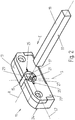
- the gear unit 11 shown forms part of a fitting for windows, doors or the like and is specially designed for insertion into a recess in a rebate of a sash of a window, a door or the like.
- the transmission unit 11 comprises a transmission housing 13, which is designed in two parts here.
- An input element 15 of the gear unit 11 is rotatably mounted in the gear housing 13 about an axis of rotation R.
- a central passage of the input element 15 has a rectangular cross section and thus forms a receptacle 17 for an in Fig. 2-5
- the square pin 19 is provided for connecting an actuating mechanism to the gear unit 11.
- the square pin 19 can be coupled to an actuating handle or lever.
- connection elements with a corresponding shape of the receptacle 17 are suitable for establishing a positive connection between an actuating element or another component of an actuating mechanism and the input element 15.
- the output element of the transmission unit 11 is through an in Fig. 1-6 Not visible drive rail is formed, which is guided displaceably in the transmission housing 13 along its longitudinal axis L1 extending transversely to the axis of rotation R and can be coupled to a drive rod of the fitting.
- a special in Fig. 1 downwardly protruding from the gear housing 13 extension of the drive rail may be provided.
- the displaceable drive rail is coupled to the input element 15 in such a way that it can be driven by rotating the input element 15 about the axis of rotation R to perform a displacement movement along its longitudinal axis L1.
- the input element 15 can be designed for this purpose as a gearwheel or gearwheel segment which meshes with a toothed rack section arranged on the displaceable drive rail.
- a further drive rail can also be displaceably mounted in the gear housing 13, which can be driven using a deflection mechanism by rotating the input element 15 to a drive movement that is opposite to the other drive rail.
- the input element 15 there are formed two input element recesses 21 offset from one another by 90 ° with respect to the axis of rotation R, which are open both towards an axial front side 22 of the transmission housing 13 and towards the receptacle 17, but towards the opposite axial rear side 24 of the gear housing 13 are limited by a stop surface 23 ( Fig. 5 ). Furthermore, two housing recesses 25 offset from one another by 180 ° with respect to the axis of rotation R are formed in the gear housing 13, which are also open both to the axial front side 22 of the gear housing 13 and to the receptacle 17, but to the axial rear side 24 of the gear housing 13 are closed.
- one of the input element recesses 21 is aligned with one of the housing recesses 25 in a radial direction with respect to the axis of rotation R.
- the other of the input element recesses 21 and the housing recesses 25 would be aligned with one another. In this way, different hardware configurations can be taken into account.
- a fixing element 27 in the form of an elastically deformable plastic part is provided, the dimensions of which are to be received in the input element recess 21 and the housing recess 25 are adapted.
- the fixing element 27 is specifically designed as an elongated rod with a square cross-sectional shape, although this shape is not mandatory.
- the fixing element 27 is inserted from the axial front side 22 along an insertion direction E into the recesses 21, 25 which are aligned with one another, until the in Fig. 2 delivery status shown has been reached.
- the longitudinal axis L2 of the fixing element 27 is aligned transversely to the axis of rotation R.
- the length of the fixing element 27 is selected such that it protrudes into the receptacle 17 in the delivery state, for example up to the center of the receptacle 17 close to the axis.
- the input element 15 and the gear housing 13 are positively connected to each other via the fixing element 27, so that the input element 15 is rotationally fixed in the middle position. This ensures that the input element 15 is correctly positioned for mounting the fitting when the gear unit 11 is in the delivery state.
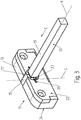
- the fixing element 27 is pivoted completely out of the housing recess 25. That is, the input element 15 is now released to rotate.
- the fixing element 27 is largely in the receptacle 17 and is between a Inner wall 31 of the receptacle 17 and an outer surface 33 of the square pin 19 are clamped. Therefore, the coupling between the square pin 19 and the input element 15 is free of play.
- the fixing element 27 is designed as a separate part from the gear housing 13 and is held positively on the gear housing 13 and on the input element 15 in the delivery state of the gear unit 11
- Fig. 6 an alternative embodiment of a gear unit 11 'according to the invention, in which the fixing element 27' is held firmly on the gear housing 13 in the delivery state of the gear unit 11 '.
- the fixing element 27 ′ is cast directly onto the gear housing 13 here.
- the fixing element 27 ' When the fixing element 27 'is acted upon by a square pin to be inserted into the receptacle 17, the fixing element 27' breaks at its end 35 on the housing side and thus detaches from the gear housing 13. The fixing element is then opened in a manner analogous to that described above with reference to Fig. 1-5 pivoted into the receptacle 17 as described.
- the fixing element 27, 27 ' not only enables a reliable central fixing of a gear unit 11, 11' or an associated fitting, but also ensures that the undesired play of the square pin 19 in the receptacle 17 is eliminated.
Landscapes
- Engineering & Computer Science (AREA)
- Mechanical Engineering (AREA)
- Transmission Devices (AREA)
- Gears, Cams (AREA)
Description
- Die vorliegende Erfindung betrifft einen Beschlag für Fenster, Türen oder dergleichen, mit einem Getriebe, welches umfasst:
- ein Getriebegehäuse,
- ein Eingangselement, das um eine Rotationsachse drehbar in dem Getriebegehäuse gelagert ist und eine Aufnahme für ein Betätigungsmechanismus-Anschlusselement wie einen Vierkantstift aufweist,
- ein mit einer Treibstange gekoppeltes oder koppelbares Ausgangselement, das durch Drehen des Eingangselements zu einer Verschiebebewegung antreibbar i ist, und ein Fixierelement, das in einem Auslieferungszustand des Beschlags einerseits am Getriebegehäuse gehalten ist und andererseits in eine Aussparung des Eingangselements eingreift, um so das Eingangselement in einer vorgegebenen Drehstellung zu fixieren, wobei das Fixierelement in die Aufnahme des Eingangselements hineinragt und zum Herstellen eines Betriebszustands des Beschlags durch Beaufschlagung mit einem in die Aufnahme einzuführenden Betätigungsmechanismus-Anschlusselement von dem Getriebegehäuse lösbar ist, und wobei das Fixierelement unter Verkippen oder Verschwenken von dem Getriebegehäuse lösbar ist.
- Derartige Beschläge werden beispielsweise als sogenannte Kantenverschlüsse in Falznuten eines Tür- oder Fensterflügels eingesetzt. Zum Schalten des Beschlags, z.B. zwecks Verriegeln oder Entriegeln des Flügels gegenüber einem Blendrahmen, wird das Eingangselement mittels eines Betätigungselements wie eines Handgriffs gedreht. Das Getriebe setzt diese Drehbewegung in eine Verschiebebewegung einer Treibstange um, welche ihrerseits die Ver- oder Entriegelung des Flügels bewirkt. Im einfachsten Fall erfolgt die Umsetzung von der Drehbewegung in eine Verschiebebewegung durch eine Anordnung aus Zahnrad und Zahnstange. Das heißt das Eingangselement kann als Zahnrad ausgebildet sein, welches mit einer die Treibstange antreibenden Zahnstange kämmt.
- Damit ein Beschlag der genannten Art ordnungsgemäß funktioniert, muss bei der Montage auf eine korrekte Lage der Bauteile und insbesondere auf eine korrekte Drehstellung des Eingangselements geachtet werden, was zeitaufwändig und lästig ist.
- Die
DE 82 03 945 U1 offenbart ein Kantengetriebe mit einer Stulpschiene und einer Stellstange, die durch ein Sicherungsmittel lösbar zueinander lagenfixiert sind. Beim erstmaligen Betätigen des Kantengetriebes wird das Sicherungsmittel abgeschert. - In der
EP 1 536 086 A1 ist ein Türschloss offenbart, bei dem durch das Einsetzen eines Schließzylinders ein elastischer Schwenkhebel aus einem blockierenden Eingriff mit einem Ritzel bewegbar ist. - Die
DE 33 27 899 A1 offenbart ein Kantengetriebe mit einem Ritzel, das im Auslieferungszustand gegenüber einem Verdrehen gesichert ist. Die Verdrehsicherung des Ritzels erfolgt mittels eines Sicherungsschiebers, der verschiebbar und unverdrehbar am Ritzel geführt ist. Der Sicherungsschieber weist einen Fortsatz auf, der in eine Ausnehmung des Gehäuses eingreift. Beim Einführen eines Vierkantdorns in die zentrale Ausnehmung des Ritzels wird der Sicherungsschieber zur Seite gedrückt, wobei der Fortsatz aus der Ausnehmung herausgleitet und dadurch die Verdrehsicherung aufgehoben wird. - Der Erfindung liegt die Aufgabe zugrunde, einen Beschlag der eingangs genannten Art anzugeben, der leichter und schneller zu montieren ist.
- Die Aufgabe wird durch einen Beschlag mit den Merkmalen des Anspruchs 1 gelöst.
- Erfindungsgemäß ist vorgesehen, dass das vom Getriebegehäuse gelöste Fixierelement aufgrund der Beaufschlagung mit dem Betätigungsmechanismus-Anschlusselement in einer Kipp- oder Schwenkbewegung um eine Kippachse in die Aufnahme hineinbewegbar ist.
- Bei dem Getriebegehäuse kann es sich um ein im Prinzip beliebig geformtes Bauteil oder eine Anordnung von Bauteilen handeln, welche zur drehbaren Lagerung des Eingangselements ausgebildet ist und direkt oder indirekt an dem Fenster, der Tür oder dergleichen befestigbar ist. Aufgrund der Fixierung des Eingangselements in einer definierten Drehstellung muss ein Monteur beim Anschlagen des Beschlags die Getriebeteile nicht eigens in die korrekte Position bewegen, sodass die Montage insgesamt wesentlich schneller erfolgen kann. Auch um das Aufheben der Fixierung des Eingangselements nach der Montage muss sich der Monteur nicht kümmern, da die Verbindung zwischen Eingangselement und Getriebegehäuse automatisch beim Einstecken des Anschlusselements - also beim in jedem Fall erfolgenden Anschließen des Betätigungsmechanismus - gelöst wird. Bei der vorgegebenen Drehstellung kann es sich - insbesondere bei Drehkippbeschlägen - um eine bezogen auf den Gesamthub des Ausgangselements mittlere Stellung handeln. Ein besonderer Vorteil der Erfindung besteht darin, dass das Fixierelement relativ einfach gestaltet sein kann und dementsprechend kostengünstig herstellbar ist.
- Das Fixierelement ist unter Verkippen oder Verschwenken von dem Getriebegehäuse lösbar.
- Es ist ferner vorgesehen, dass das vom Getriebegehäuse gelöste Fixierelement aufgrund der Beaufschlagung mit dem Betätigungsmechanismus-Anschlusselement in die Aufnahme hineinbewegbar ist.
- Bevorzugt ist das vom Getriebegehäuse gelöste Fixierelement unter Verklemmung zwischen einer Innenwand der Aufnahme und einer Außenfläche des Betätigungsmechanismus-Anschlusselements in die Aufnahme hineinbewegbar. Durch das Hineinbewegen des Fixierelements in die Aufnahme wird die Fixierung gelöst und das Eingangselement ist fortan für eine Drehbewegung freigegeben. Zugleich wird aufgrund der Verklemmung des Fixierelements das unweigerlich vorhandene Spiel des Betätigungsmechanismus-Anschlusselements in der Aufnahme beseitigt.
- Das Fixierelement ist in einer Kipp- oder Schwenkbewegung um eine Kippachse in die Aufnahme hineinbewegbar. Dadurch gelangt es beim Einführen des Betätigungsmechanismus-Anschlusselements in die Aufnahme besonders schnell aus einem Eingriff mit dem Getriebegehäuse.
- Die Aussparung des Eingangselements kann in einer bezüglich der Rotationsachse axialen Richtung durch eine Anschlagfläche begrenzt sein, welche hinsichtlich der Kipp- oder Schwenkbewegung ein Widerlager für das Fixierelement bildet. Bei einem Einführen des Betätigungsmechanismus-Anschlusselements in die Aufnahme drückt dessen Vorderfläche auf den in die Aufnahme ragenden Abschnitt des Fixierelements, welches aufgrund der Anschlagfläche nur in einer Schwenkbewegung ausweichen kann. Im Ergebnis wird das gesamte Fixierelement in die Aufnahme hineingedrückt. Bei Bedarf kann an der Innenwand der Aufnahme eine Ausnehmung zur teilweisen Aufnahme des Fixierelements ausgebildet sein.
- Gemäß einer Ausgestaltung der Erfindung ist das Fixierelement länglich, wobei die Längsachse des Fixierelements in dem Auslieferungszustand des Beschlags quer zu der Rotationsachse ausgerichtet ist. Ein längliches und quer zur Rotationsachse ausgerichtetes Fixierelement eignet sich besonders gut zum Verbinden benachbarter Abschnitte des Getriebegehäuses und des Eingangselements. Insbesondere kann das Fixierelement als einfacher Stab oder Streifen gestaltet sein.
- Gemäß einer speziellen Ausgestaltung weist das längliche Fixierelement ein erstes Ende und ein zweites Ende auf, wobei das erste Ende am Getriebegehäuse gehalten ist und das zweite Ende in die Aufnahme des Eingangselements hineinragt.
- Eine Ausführungsform der Erfindung sieht vor, dass das Fixierelement als vom Getriebegehäuse separates Teil ausgeführt ist und in dem Auslieferungszustand des Beschlags durch einen Eingriff in eine Aussparung des Getriebegehäuses formschlüssig am Getriebegehäuse gehalten ist. Ein solches separates Fixierelement ist mittels einer Beaufschlagung durch das Betätigungsmechanismus-Anschlusselement leicht innerhalb der Aussparungen bewegbar. Aufgrund des in Drehrichtung wirkenden Formschlusses ist eine Rotation des Eingangselements nur unter Wegbewegen oder Zerstören des Fixierelements möglich.
- Das Fixierelement kann zum Lösen vom Getriebegehäuse in eine Freigabestellung bewegbar sein, in welcher es nicht in die Aussparung des Getriebegehäuses eingreift. Somit kann die Blockade des Eingangselements durch einfaches Herausbewegen des Fixierelements aus der Aussparung des Getriebegehäuses aufgehoben werden. Ein Abscheren oder anderweitiges Zerstören des Fixierelements ist bei dieser Ausgestaltung nicht erforderlich.
- Das Fixierelement kann zum Lösen vom Getriebegehäuse aus der Aussparung des Getriebegehäuses herausschwenkbar sein.
- Die Aussparung des Getriebegehäuses und die Aussparung des Eingangselements können jeweils zu einer bezüglich der Rotationsachse axialen Seite hin geöffnet sein, um ein leichtes Einsetzen des Fixierelements im Rahmen der Herstellung zu ermöglichen. Vorzugsweise sind die Aussparung des Getriebegehäuses und die Aussparung des Eingangselements zu derjenigen axialen Seite hin geöffnet, von welcher aus bei bestimmungsgemäßer Montage des Beschlags das Einführen des Betätigungsmechanismus-Anschlusselements erfolgt.
- Eine alternative Ausführungsform der Erfindung sieht vor, dass das Fixierelement in dem Auslieferungszustand des Beschlags stoffschlüssig am Getriebegehäuse gehalten ist, insbesondere wobei das Fixierelement an das Getriebegehäuse angeformt ist. Das Getriebegehäuse könnte beispielsweise einschließlich des Fixierelements als kostengünstiges Gussbauteil hergestellt sein. Ein Lösen des Fixierelements vom Getriebegehäuse ist bei dieser Ausgestaltung z. B. durch Abscheren des Fixierelements infolge eines entsprechenden Kraftaufwands möglich.
- Das Fixierelement kann elastisch verformbar sein. Auf diese Weise kann ein Verklemmen oder Verkeilen des Fixierelements zwischen Aufnahme und Betätigungsmechanismus-Anschlusselement unterstützt werden. Selbst eine geringfügige Erweiterung des Abstands zwischen der Innenwand der Aufnahme und der Außenfläche des Betätigungsmechanismus-Anschlusselements nach der Montage kann durch ein in dem betreffenden Spalt verklemmtes elastisches Fixierelement kompensiert werden.
- Das Fixierelement kann aus Kunststoff gefertigt sein, um eine einfache und kostengünstige Fertigung zu ermöglichen.
- Gemäß einer weiteren Ausgestaltung weist das Fixierelement eine rechteckige, insbesondere quadratische, Querschnittsform auf. Insbesondere kann das Fixierelement als einfacher Rechteckstab ausgeführt sein. Dies ermöglicht eine kostengünstige Herstellung und erleichtert die Aufnahme in einer geradwandigen Aussparung.
- Die Erfindung betrifft auch eine Getriebeeinheit eines Beschlags für Fenster, Türen oder dergleichen, welche umfasst:
- ein Getriebegehäuse,
- ein Eingangselement, das um eine Rotationsachse drehbar in dem Getriebegehäuse gelagert ist und eine Aufnahme für ein Betätigungsmechanismus-Anschlusselement wie einen Vierkantstift aufweist, und
- ein mit einer Treibstange des Beschlags koppelbares Ausgangselement, das durch Drehen des Eingangselements zu einer Verschiebebewegung antreibbar ist.
- Erfindungsgemäß umfasst eine solche Getriebeeinheit ein Fixierelement, das in einem Auslieferungszustand der Getriebeeinheit einerseits am Getriebegehäuse gehalten ist und andererseits in eine Aussparung des Eingangselements eingreift, um so das Eingangselement in einer vorgegebenen Drehstellung zu fixieren, wobei das Fixierelement in die Aufnahme des Eingangselements hineinragt und zum Herstellen eines Betriebszustands der Getriebeeinheit durch Beaufschlagung mit einem in die Aufnahme einzuführenden Betätigungsmechanismus-Anschlusselement von dem Getriebegehäuse lösbar ist.
- Die Fixierung des Eingangselements in einer definierten Drehstellung, z. B. einer Mittelstellung, ermöglicht eine schnelle und einfache Montage des zugehörigen Beschlags. Das Getriebegehäuse kann einen oder mehrere Kopplungsabschnitte für eine Anbindung an weitere Beschlagteile oder an einen Tür- oder Fensterflügel aufweisen.
- Weiterbildungen der Erfindung sind auch in den abhängigen Ansprüchen, der Beschreibung sowie den beigefügten Zeichnungen angegeben.
- Die Erfindung wird nachfolgend beispielhaft unter Bezugnahme auf die Zeichnung beschrieben.
- Fig. 1
- ist eine perspektivische Darstellung einer erfindungsgemäßen Getriebeeinheit eines Beschlags für Fenster, Türen oder dergleichen.
- Fig. 2-4
- zeigen die Getriebeeinheit gemäß
Fig. 1 in verschiedenen aufeinanderfolgenden Phasen eines Montagevorgangs. - Fig. 5
- ist eine Schnittdarstellung, welche die Getriebeeinheit in der Phase gemäß
Fig. 4 zeigt. - Fig. 6
- ist eine perspektivische Darstellung einer alternativ gestalteten erfindungsgemäßen Getriebeeinheit eines Beschlags für Fenster, Türen oder dergleichen.
- Die in
Fig. 1 gezeigte Getriebeeinheit 11 bildet einen Teil eines Beschlags für Fenster, Türen oder dergleichen und ist speziell zum Einsetzen in eine Ausnehmung in einem Falz eines Flügels eines Fensters, einer Tür oder dergleichen ausgelegt. Die Getriebeeinheit 11 umfasst ein Getriebegehäuse 13, welches hier zweiteilig ausgeführt ist. Ein Eingangselement 15 der Getriebeeinheit 11 ist um eine Rotationsachse R drehbar in dem Getriebegehäuse 13 gelagert. Eine zentrale Durchführung des Eingangselements 15 weist einen rechteckigen Querschnitt auf und bildet somit eine Aufnahme 17 für einen inFig. 2-5 gezeigten Vierkantstift 19. Der Vierkantstift 19 ist zum Anschluss eines Betätigungsmechanismus an die Getriebeeinheit 11 vorgesehen. Beispielsweise kann der Vierkantstift 19 mit einem Betätigungsgriff oder -hebel gekoppelt sein. Es versteht sich, dass außer einem Vierkantstift 19 eine Vielzahl anders gestalteter Anschlusselemente bei entsprechender Formgebung der Aufnahme 17 geeignet sind, eine formschlüssige Verbindung zwischen einem Betätigungselement oder einer anderen Komponente eines Betätigungsmechanismus und dem Eingangselement 15 herzustellen. - Das Ausgangselement der Getriebeeinheit 11 ist durch eine in
Fig. 1-6 nicht sichtbare Antriebsschiene gebildet, die entlang ihrer quer zu der Rotationsachse R verlaufenden Längsachse L1 verschiebbar im Getriebegehäuse 13 geführt ist und mit einer Treibstange des Beschlags koppelbar ist. Zur Kopplung mit der Treibstange kann speziell ein inFig. 1 nach unten aus dem Getriebegehäuse 13 ragender Fortsatz der Antriebsschiene vorgesehen sein. - Die verschiebbare Antriebsschiene ist derart mit dem Eingangselement 15 gekoppelt, dass sie durch Drehen des Eingangselements 15 um die Rotationsachse R zu einer Verschiebebewegung entlang ihrer Längsachse L1 antreibbar ist. Im einfachsten Fall kann zu diesem Zweck das Eingangselement 15 als Zahnrad oder Zahnradsegment ausgebildet sein, welches mit einem an der verschiebbaren Antriebsschiene angeordneten Zahnstangenabschnitt kämmt. Es kann auch eine weitere Antriebsschiene verschiebbar in dem Getriebegehäuse 13 gelagert sein, welche unter Verwendung eines Umlenkmechanismus durch Drehen des Eingangselements 15 zu einer bezogen auf die andere Antriebsschiene gegenläufigen Antriebsbewegung antreibbar ist.
- In dem Eingangselement 15 sind zwei bezüglich der Rotationsachse R um 90° zueinander versetzt angeordnete Eingangselement-Aussparungen 21 ausgebildet, welche sowohl zu einer axialen Vorderseite 22 des Getriebegehäuses 13 hin als auch zu der Aufnahme 17 hin geöffnet sind, jedoch zu der entgegengesetzten axialen Rückseite 24 des Getriebegehäuses 13 hin durch eine Anschlagfläche 23 begrenzt sind (
Fig. 5 ). Ferner sind in dem Getriebegehäuse 13 zwei bezüglich der Rotationsachse R um 180° zueinander versetzt angeordnete Gehäuse-Aussparungen 25 ausgebildet, welche ebenfalls sowohl zur axialen Vorderseite 22 des Getriebegehäuses 13 hin als auch zur Aufnahme 17 hin geöffnet sind, jedoch zur axialen Rückseite 24 des Getriebegehäuses 13 hin geschlossen sind. Wenn sich das Eingangselement 15 wie inFig. 1 dargestellt in einer vorgegebenen Mittelstellung oder Grundstellung befindet, fluchtet eine der Eingangselement-Aussparungen 21 mit einer der Gehäuse-Aussparungen 25 in bezüglich der Rotationsachse R radialer Richtung. Bei einem um 90° gegen den Uhrzeigersinn verdrehten Eingangselement 15 würden die jeweils anderen der Eingangselement-Aussparungen 21 und der Gehäuse-Aussparungen 25 miteinander fluchten. Auf diese Weise können unterschiedliche Beschlagkonfigurationen berücksichtigt werden. - Zur Fixierung der Drehstellung des Eingangselements 15 in einem Auslieferungszustand der Getriebeeinheit 11 ist ein Fixierelement 27 in Form eines elastisch verformbaren Kunststoffteils vorgesehen, dessen Abmessungen für eine Aufnahme in der Eingangselement-Aussparung 21 und der Gehäuse-Aussparung 25 angepasst sind. Speziell ist das Fixierelement 27 als länglicher Stab mit quadratischer Querschnittsform ausgeführt, wobei diese Formgebung allerdings nicht zwingend ist.
- Bei der Herstellung der Getriebeeinheit 11 wird das Fixierelement 27 von der axialen Vorderseite 22 aus entlang einer Einsteckrichtung E in die miteinander fluchtenden Aussparungen 21, 25 eingesteckt, bis der in
Fig. 2 gezeigte Auslieferungszustand erreicht ist. Die Längsachse L2 des Fixierelements 27 ist dabei quer zu der Rotationsachse R ausgerichtet. Weiterhin ist die Länge des Fixierelements 27 derart gewählt, dass dieses in dem Auslieferungszustand in die Aufnahme 17 hineinragt, beispielsweise bis zum achsnahen Zentrum der Aufnahme 17. Über das Fixierelement 27 sind das Eingangselement 15 und das Getriebegehäuse 13 formschlüssig miteinander verbunden, sodass das Eingangselement 15 in der Mittelstellung drehfixiert ist. Somit ist sichergestellt, dass das Eingangselement 15 für eine Montage des Beschlags korrekt positioniert ist, wenn sich die Getriebeeinheit 11 in dem Auslieferungszustand befindet. - Wenn im Rahmen der Beschlagmontage ein Vierkantstift 19 entlang der Einsteckrichtung E in die Aufnahme 17 eingeführt wird, beaufschlagt er den in die Aufnahme 17 ragenden Schenkel 29 des Fixierelements 27 und verschwenkt das Fixierelement 27 um eine rechtwinklig zur Rotationsachse R verlaufende Kippachse S, wie in
Fig. 3 zu erkennen ist. Die Anschlagfläche 23 (Fig. 5 ) bildet hierbei hinsichtlich der Schwenkbewegung ein Widerlager für das Fixierelement 27. Der Schwenkvorgang hält beim weiteren Einführen des Vierkantstifts 19 solange an, bis der inFig. 4 und5 gezeigte Betriebszustand der Getriebeeinheit 11 erreicht ist. In diesem Zustand verläuft die Längsachse L2 des Fixierelements 27 parallel zur Rotationsachse R. Ferner ist das Fixierelement 27 vollständig aus der Gehäuse-Aussparung 25 herausgeschwenkt. Das heißt das Eingangselement 15 ist nun zum Drehen freigegeben. Wie insbesondere inFig. 5 zu erkennen ist, befindet sich das Fixierelement 27 weitgehend in der Aufnahme 17 und ist zwischen einer Innenwand 31 der Aufnahme 17 und einer Außenfläche 33 des Vierkantstifts 19 eingeklemmt. Daher ist die Kopplung zwischen dem Vierkantstift 19 und dem Eingangselement 15 spielfrei. - Während bei der in
Fig. 1-5 dargestellten Ausführungsform einer erfindungsgemäßen Getriebeeinheit 11 das Fixierelement 27 als vom Getriebegehäuse 13 separates Teil ausgeführt ist und im Auslieferungszustand der Getriebeeinheit 11 formschlüssig am Getriebegehäuse 13 und am Eingangselement 15 gehalten ist, zeigtFig. 6 eine alternative Ausführungsform einer erfindungsgemäßen Getriebeeinheit 11', bei welcher das Fixierelement 27' im Auslieferungszustand der Getriebeeinheit 11' stoffschlüssig am Getriebegehäuse 13 gehalten ist. Speziell ist das Fixierelement 27' hier direkt an das Getriebegehäuse 13 angegossen. - Bei einer Beaufschlagung des Fixierelements 27' mit einem in die Aufnahme 17 einzuführenden Vierkantstift bricht das Fixierelement 27' an seinem gehäuseseitigen Ende 35 und löst sich somit von dem Getriebegehäuse 13. Anschließend wird das Fixierelement in analoger Weise wie vorstehend unter Bezugnahme auf
Fig. 1-5 beschrieben in die Aufnahme 17 hineingeschwenkt. - Das Fixierelement 27, 27' ermöglicht nicht nur eine zuverlässige Mittenfixierung einer Getriebeeinheit 11, 11' bzw. eines zugehörigen Beschlags, sondern sorgt zusätzlich auch für eine Beseitigung des unerwünschten Spiels des Vierkantstifts 19 in der Aufnahme 17.
-
- 11, 11'
- Getriebeeinheit
- 13
- Getriebegehäuse
- 15
- Eingangselement
- 17
- Aufnahme
- 19
- Vierkantstift
- 21
- Eingangselement-Aussparung
- 22
- axiale Vorderseite
- 23
- Anschlagfläche
- 24
- axiale Rückseite
- 25
- Gehäuse-Aussparung
- 27, 27'
- Fixierelement
- 29
- Schenkel
- 31
- Innenwand
- 33
- Außenfläche
- 35
- gehäuseseitiges Ende
- R
- Rotationsachse
- L1
- Längsachse der Antriebsschiene
- L2
- Längsachse des Fixierelements
- E
- Einsteckrichtung
- S
- Kippachse
Claims (12)
- Beschlag für Fenster, Türen oder dergleichen, mit einem Getriebe, welches umfasst:ein Getriebegehäuse (13),ein Eingangselement (15), das um eine Rotationsachse (R) drehbar in dem Getriebegehäuse (13) gelagert ist und eine Aufnahme (17) für ein Betätigungsmechanismus-Anschlusselement (19) wie einen Vierkantstift aufweist, ein mit einer Treibstange gekoppeltes oder koppelbares Ausgangselement, das durch Drehen des Eingangselements (15) zu einer Verschiebebewegung antreibbar ist, undein Fixierelement (27, 27'), das in einem Auslieferungszustand des Beschlags einerseits am Getriebegehäuse (13) gehalten ist und andererseits in eine Aussparung (21) des Eingangselements (15) eingreift, um so das Eingangselement (15) in einer vorgegebenen Drehstellung zu fixieren, wobeidas Fixierelement (27, 27') in die Aufnahme (17) des Eingangselements (15) hineinragt und zum Herstellen eines Betriebszustands des Beschlags durch Beaufschlagung mit einem in die Aufnahme (17) einzuführenden Betätigungsmechanismus-Anschlusselement (19) von dem Getriebegehäuse (13) lösbar ist, und wobeidas Fixierelement (27, 27') unter Verkippen oder Verschwenken von dem Getriebegehäuse (13) lösbar ist,dadurch gekennzeichnet, dassdas vom Getriebegehäuse (13) gelöste Fixierelement (27, 27') aufgrund der Beaufschlagung mit dem Betätigungsmechanismus-Anschlusselement (19) in einer Kipp- oder Schwenkbewegung um eine Kippachse (S) in die Aufnahme (17) hineinbewegbar ist.
- Beschlag nach Anspruch 1,
dadurch gekennzeichnet, dass
das vom Getriebegehäuse (13) gelöste Fixierelement (27, 27') unter Verklemmung zwischen einer Innenwand (31) der Aufnahme (17) und einer Außenfläche (33) des Betätigungsmechanismus-Anschlusselements (19) in die Aufnahme (17) hineinbewegbar ist. - Beschlag nach Anspruch 1 oder 2,
dadurch gekennzeichnet, dass
die Aussparung (21) des Eingangselements (15) in einer bezüglich der Rotationsachse (R) axialen Richtung durch eine Anschlagfläche (23) begrenzt ist, welche hinsichtlich der Kipp- oder Schwenkbewegung ein Widerlager für das Fixierelement (27, 27') bildet. - Beschlag nach einem der vorstehenden Ansprüche,
dadurch gekennzeichnet, dass
das Fixierelement (27, 27') länglich ist, wobei die Längsachse (L2) des Fixierelements (27, 27') in dem Auslieferungszustand des Beschlags quer zu der Rotationsachse (R) ausgerichtet ist. - Beschlag nach Anspruch 4,
dadurch gekennzeichnet, dass
das längliche Fixierelement (27, 27') ein erstes Ende (35) und ein zweites Ende aufweist, wobei das erste Ende (35) am Getriebegehäuse (13) gehalten ist und das zweite Ende in die Aufnahme (17) des Eingangselements (15) hineinragt. - Beschlag nach einem der vorstehenden Ansprüche,
dadurch gekennzeichnet, dass
das Fixierelement (27) als vom Getriebegehäuse (13) separates Teil ausgeführt ist und in dem Auslieferungszustand des Beschlags durch einen Eingriff in eine Aussparung (25) des Getriebegehäuses (13) formschlüssig am Getriebegehäuse (13) gehalten ist. - Beschlag nach Anspruch 6,
dadurch gekennzeichnet, dass
das Fixierelement (27) zum Lösen vom Getriebegehäuse (13) in eine Freigabestellung bewegbar ist, in welcher es nicht in die Aussparung (25) des Getriebegehäuses (13) eingreift. - Beschlag nach Anspruch 7,
dadurch gekennzeichnet, dass
das Fixierelement (27) zum Lösen vom Getriebegehäuse (13) aus der Aussparung (25) des Getriebegehäuses (13) herausschwenkbar ist. - Beschlag nach einem der Ansprüche 6 bis 8,
dadurch gekennzeichnet, dass
die Aussparung (25) des Getriebegehäuses (13) und die Aussparung (21) des Eingangselements (15) jeweils zu einer bezüglich der Rotationsachse (R) axialen Seite hin geöffnet sind. - Beschlag nach einem der Ansprüche 1 bis 5,
dadurch gekennzeichnet, dass
das Fixierelement (27') in dem Auslieferungszustand des Beschlags stoffschlüssig am Getriebegehäuse (13) gehalten ist, insbesondere wobei das Fixierelement (27') an das Getriebegehäuse (13) angeformt ist. - Beschlag nach einem der vorstehenden Ansprüche,
dadurch gekennzeichnet, dass
das Fixierelement (27, 27') elastisch verformbar ist. - Beschlag nach einem der vorstehenden Ansprüche,
dadurch gekennzeichnet, dass
das Fixierelement (27, 27') aus Kunststoff gefertigt ist und/oder dass das Fixierelement (27, 27') eine rechteckige, insbesondere quadratische, Querschnittsform aufweist.
Priority Applications (1)
| Application Number | Priority Date | Filing Date | Title |
|---|---|---|---|
| PL15804352T PL3194690T3 (pl) | 2014-11-27 | 2015-11-24 | Okucie dla okien, drzwi i tym podobnych zamknięć |
Applications Claiming Priority (2)
| Application Number | Priority Date | Filing Date | Title |
|---|---|---|---|
| DE102014117419.4A DE102014117419A1 (de) | 2014-11-27 | 2014-11-27 | Beschlag für Fenster, Türen und dergleichen und Getriebeeinheit für einen solchen Beschlag |
| PCT/EP2015/077537 WO2016083395A1 (de) | 2014-11-27 | 2015-11-24 | Beschlag für fenster, türen und dergleichen und getriebeeinheit für einen solchen beschlag |
Publications (2)
| Publication Number | Publication Date |
|---|---|
| EP3194690A1 EP3194690A1 (de) | 2017-07-26 |
| EP3194690B1 true EP3194690B1 (de) | 2020-12-30 |
Family
ID=54780264
Family Applications (1)
| Application Number | Title | Priority Date | Filing Date |
|---|---|---|---|
| EP15804352.1A Active EP3194690B1 (de) | 2014-11-27 | 2015-11-24 | Beschlag für fenster, türen oder dergleichen |
Country Status (4)
| Country | Link |
|---|---|
| EP (1) | EP3194690B1 (de) |
| DE (1) | DE102014117419A1 (de) |
| PL (1) | PL3194690T3 (de) |
| WO (1) | WO2016083395A1 (de) |
Families Citing this family (2)
| Publication number | Priority date | Publication date | Assignee | Title |
|---|---|---|---|---|
| DE102017215611A1 (de) * | 2017-09-05 | 2019-03-07 | Aug. Winkhaus Gmbh & Co. Kg | Antriebseinrichtung eines Treibstangenbeschlages und Verfahren zur Montage einer solchen Antriebseinrichtung |
| WO2021239319A1 (de) * | 2020-05-28 | 2021-12-02 | Michael Weltzer | Fenstergriffkupplung mit dehnstoffantrieb und fenster mit fenstergriffkupplung |
Citations (1)
| Publication number | Priority date | Publication date | Assignee | Title |
|---|---|---|---|---|
| DE3327899A1 (de) * | 1983-08-02 | 1985-02-21 | Winkhaus, August, 4404 Telgte | Kantengetriebe fuer ein fenster, eine tuer od. dergl. |
Family Cites Families (7)
| Publication number | Priority date | Publication date | Assignee | Title |
|---|---|---|---|---|
| DE3114776C2 (de) * | 1981-04-11 | 1983-10-27 | Press- Und Stanzwerk Friedrich R. Brumme, 5620 Velbert | "Zahnradantrieb in einem schließzylinderbetätigbarem Schloß" |
| DE8203945U1 (de) * | 1982-02-12 | 1982-05-19 | Wilh. Frank Gmbh, 7022 Leinfelden-Echterdingen | Kantengetriebe fuer ein fenster, eine tuer od. dgl. |
| DE19911894A1 (de) * | 1999-03-17 | 2000-09-28 | Siegenia Frank Kg | Kantengetriebe |
| FR2794787B1 (fr) * | 1999-06-11 | 2002-05-10 | Ferco Int Usine Ferrures | Dispositif de renvoi de fouillot |
| EP1536086A1 (de) * | 2003-11-28 | 2005-06-01 | CISA S.p.A. | Schloss mit Vorrichtung zum Verhindern von Lageabweichungen des angetriebenen Zahnrads eines Schliess- bzw. Öffnungsmechanismus bei der Einführung des Schlüsselbetätigten Zylinders in das Schloss |
| DE202007016853U1 (de) * | 2007-11-30 | 2009-04-02 | Siegenia-Aubi Kg | Treibstangenantrieb |
| EP2735677B1 (de) * | 2012-11-21 | 2017-01-04 | Vita Corporation Co., Ltd. | Tür/Fenster mit einem Betriebssystem mit mehreren Verschlussstellen |
-
2014
- 2014-11-27 DE DE102014117419.4A patent/DE102014117419A1/de not_active Withdrawn
-
2015
- 2015-11-24 EP EP15804352.1A patent/EP3194690B1/de active Active
- 2015-11-24 WO PCT/EP2015/077537 patent/WO2016083395A1/de not_active Ceased
- 2015-11-24 PL PL15804352T patent/PL3194690T3/pl unknown
Patent Citations (1)
| Publication number | Priority date | Publication date | Assignee | Title |
|---|---|---|---|---|
| DE3327899A1 (de) * | 1983-08-02 | 1985-02-21 | Winkhaus, August, 4404 Telgte | Kantengetriebe fuer ein fenster, eine tuer od. dergl. |
Also Published As
| Publication number | Publication date |
|---|---|
| WO2016083395A1 (de) | 2016-06-02 |
| EP3194690A1 (de) | 2017-07-26 |
| PL3194690T3 (pl) | 2021-06-28 |
| DE102014117419A1 (de) | 2016-06-02 |
Similar Documents
| Publication | Publication Date | Title |
|---|---|---|
| EP1978187B1 (de) | Beschlaganordnung für ein Fenster, eine Tür oder dergleichen | |
| EP2348177B1 (de) | Verschluss eines Treibstangenbeschlages | |
| EP3194690A1 (de) | Beschlag für fenster, türen und dergleichen und getriebeeinheit für einen solchen beschlag | |
| EP2172606B1 (de) | Drückeranordnung | |
| EP2503080B1 (de) | Federklemmnuss | |
| EP3018269B1 (de) | Griffanordnung für ein fenster oder dergleichen sowie fenster oder dergleichen mit griffanordnung | |
| EP1683938B1 (de) | Verschluss für einen Treibstangenbeschlag | |
| EP1739260B1 (de) | Getriebe eines Beschlags eines Fensters, einer Tür oder dergleichen sowie Verfahren zum Betätigen des Getriebes | |
| DE202005000939U1 (de) | Verriegelungseinrichtung | |
| EP3626916B1 (de) | Treibstangenbeschlag | |
| EP2149660B1 (de) | Antriebsgehäuse für einen Treibstangenbeschlag | |
| EP2607583B1 (de) | Beschlagteil für einen treibstangenbeschlag | |
| EP2085543B1 (de) | Schloss | |
| EP3269903B1 (de) | Rosettengarnitur für drücker bei türen oder fenstern | |
| EP2216470B1 (de) | Verschluss für einen Treibstangenbeschlag | |
| DE102014111131A1 (de) | Vorrichtung zur Ver- und Entriegelung eines Fensterflügels, einer Lüftungsklappe oder dergleichen an einem Blendrahmen | |
| EP2754791A1 (de) | Treibriegelschloss | |
| EP3162994B1 (de) | Antriebsgetriebe für einen treibstangenbeschlag | |
| EP2320013B1 (de) | Beschlag mit einem Umkehrgetriebe | |
| EP2365164A2 (de) | Verschlussvorrichtung | |
| EP2453086A1 (de) | Treibstangenbeschlag für Standflügel von zweiflügeligen Fenstern oder Türen ohne Mittelpfosten | |
| EP1619332B1 (de) | Antriebsgetriebe für einen Treibstangenbeschlag | |
| EP3112567A1 (de) | Einrichtung zur aktivierung bzw. deaktivierung einer tagfunktion bei einem schloss | |
| DE202006004589U1 (de) | Schubstangengetriebe | |
| EP1884612B1 (de) | Beschlagteil für einen Treibstangenbeschlag |
Legal Events
| Date | Code | Title | Description |
|---|---|---|---|
| STAA | Information on the status of an ep patent application or granted ep patent |
Free format text: STATUS: THE INTERNATIONAL PUBLICATION HAS BEEN MADE |
|
| PUAI | Public reference made under article 153(3) epc to a published international application that has entered the european phase |
Free format text: ORIGINAL CODE: 0009012 |
|
| STAA | Information on the status of an ep patent application or granted ep patent |
Free format text: STATUS: REQUEST FOR EXAMINATION WAS MADE |
|
| 17P | Request for examination filed |
Effective date: 20170419 |
|
| AK | Designated contracting states |
Kind code of ref document: A1 Designated state(s): AL AT BE BG CH CY CZ DE DK EE ES FI FR GB GR HR HU IE IS IT LI LT LU LV MC MK MT NL NO PL PT RO RS SE SI SK SM TR |
|
| AX | Request for extension of the european patent |
Extension state: BA ME |
|
| DAV | Request for validation of the european patent (deleted) | ||
| DAX | Request for extension of the european patent (deleted) | ||
| STAA | Information on the status of an ep patent application or granted ep patent |
Free format text: STATUS: EXAMINATION IS IN PROGRESS |
|
| 17Q | First examination report despatched |
Effective date: 20190529 |
|
| RIC1 | Information provided on ipc code assigned before grant |
Ipc: E05C 9/04 20060101ALN20200525BHEP Ipc: E05C 9/10 20060101ALI20200525BHEP Ipc: E05C 9/02 20060101ALN20200525BHEP Ipc: E05B 17/00 20060101AFI20200525BHEP |
|
| GRAP | Despatch of communication of intention to grant a patent |
Free format text: ORIGINAL CODE: EPIDOSNIGR1 |
|
| STAA | Information on the status of an ep patent application or granted ep patent |
Free format text: STATUS: GRANT OF PATENT IS INTENDED |
|
| INTG | Intention to grant announced |
Effective date: 20200706 |
|
| GRAS | Grant fee paid |
Free format text: ORIGINAL CODE: EPIDOSNIGR3 |
|
| GRAA | (expected) grant |
Free format text: ORIGINAL CODE: 0009210 |
|
| STAA | Information on the status of an ep patent application or granted ep patent |
Free format text: STATUS: THE PATENT HAS BEEN GRANTED |
|
| AK | Designated contracting states |
Kind code of ref document: B1 Designated state(s): AL AT BE BG CH CY CZ DE DK EE ES FI FR GB GR HR HU IE IS IT LI LT LU LV MC MK MT NL NO PL PT RO RS SE SI SK SM TR |
|
| REG | Reference to a national code |
Ref country code: GB Ref legal event code: FG4D Free format text: NOT ENGLISH |
|
| REG | Reference to a national code |
Ref country code: DE Ref legal event code: R096 Ref document number: 502015014093 Country of ref document: DE |
|
| REG | Reference to a national code |
Ref country code: AT Ref legal event code: REF Ref document number: 1350064 Country of ref document: AT Kind code of ref document: T Effective date: 20210115 |
|
| REG | Reference to a national code |
Ref country code: IE Ref legal event code: FG4D Free format text: LANGUAGE OF EP DOCUMENT: GERMAN |
|
| PG25 | Lapsed in a contracting state [announced via postgrant information from national office to epo] |
Ref country code: FI Free format text: LAPSE BECAUSE OF FAILURE TO SUBMIT A TRANSLATION OF THE DESCRIPTION OR TO PAY THE FEE WITHIN THE PRESCRIBED TIME-LIMIT Effective date: 20201230 Ref country code: RS Free format text: LAPSE BECAUSE OF FAILURE TO SUBMIT A TRANSLATION OF THE DESCRIPTION OR TO PAY THE FEE WITHIN THE PRESCRIBED TIME-LIMIT Effective date: 20201230 Ref country code: NO Free format text: LAPSE BECAUSE OF FAILURE TO SUBMIT A TRANSLATION OF THE DESCRIPTION OR TO PAY THE FEE WITHIN THE PRESCRIBED TIME-LIMIT Effective date: 20210330 Ref country code: GR Free format text: LAPSE BECAUSE OF FAILURE TO SUBMIT A TRANSLATION OF THE DESCRIPTION OR TO PAY THE FEE WITHIN THE PRESCRIBED TIME-LIMIT Effective date: 20210331 |
|
| PG25 | Lapsed in a contracting state [announced via postgrant information from national office to epo] |
Ref country code: LV Free format text: LAPSE BECAUSE OF FAILURE TO SUBMIT A TRANSLATION OF THE DESCRIPTION OR TO PAY THE FEE WITHIN THE PRESCRIBED TIME-LIMIT Effective date: 20201230 Ref country code: SE Free format text: LAPSE BECAUSE OF FAILURE TO SUBMIT A TRANSLATION OF THE DESCRIPTION OR TO PAY THE FEE WITHIN THE PRESCRIBED TIME-LIMIT Effective date: 20201230 Ref country code: BG Free format text: LAPSE BECAUSE OF FAILURE TO SUBMIT A TRANSLATION OF THE DESCRIPTION OR TO PAY THE FEE WITHIN THE PRESCRIBED TIME-LIMIT Effective date: 20210330 |
|
| REG | Reference to a national code |
Ref country code: NL Ref legal event code: MP Effective date: 20201230 |
|
| PG25 | Lapsed in a contracting state [announced via postgrant information from national office to epo] |
Ref country code: HR Free format text: LAPSE BECAUSE OF FAILURE TO SUBMIT A TRANSLATION OF THE DESCRIPTION OR TO PAY THE FEE WITHIN THE PRESCRIBED TIME-LIMIT Effective date: 20201230 |
|
| REG | Reference to a national code |
Ref country code: LT Ref legal event code: MG9D |
|
| PG25 | Lapsed in a contracting state [announced via postgrant information from national office to epo] |
Ref country code: RO Free format text: LAPSE BECAUSE OF FAILURE TO SUBMIT A TRANSLATION OF THE DESCRIPTION OR TO PAY THE FEE WITHIN THE PRESCRIBED TIME-LIMIT Effective date: 20201230 Ref country code: SK Free format text: LAPSE BECAUSE OF FAILURE TO SUBMIT A TRANSLATION OF THE DESCRIPTION OR TO PAY THE FEE WITHIN THE PRESCRIBED TIME-LIMIT Effective date: 20201230 Ref country code: PT Free format text: LAPSE BECAUSE OF FAILURE TO SUBMIT A TRANSLATION OF THE DESCRIPTION OR TO PAY THE FEE WITHIN THE PRESCRIBED TIME-LIMIT Effective date: 20210430 Ref country code: LT Free format text: LAPSE BECAUSE OF FAILURE TO SUBMIT A TRANSLATION OF THE DESCRIPTION OR TO PAY THE FEE WITHIN THE PRESCRIBED TIME-LIMIT Effective date: 20201230 Ref country code: EE Free format text: LAPSE BECAUSE OF FAILURE TO SUBMIT A TRANSLATION OF THE DESCRIPTION OR TO PAY THE FEE WITHIN THE PRESCRIBED TIME-LIMIT Effective date: 20201230 Ref country code: CZ Free format text: LAPSE BECAUSE OF FAILURE TO SUBMIT A TRANSLATION OF THE DESCRIPTION OR TO PAY THE FEE WITHIN THE PRESCRIBED TIME-LIMIT Effective date: 20201230 Ref country code: NL Free format text: LAPSE BECAUSE OF FAILURE TO SUBMIT A TRANSLATION OF THE DESCRIPTION OR TO PAY THE FEE WITHIN THE PRESCRIBED TIME-LIMIT Effective date: 20201230 |
|
| PG25 | Lapsed in a contracting state [announced via postgrant information from national office to epo] |
Ref country code: IS Free format text: LAPSE BECAUSE OF FAILURE TO SUBMIT A TRANSLATION OF THE DESCRIPTION OR TO PAY THE FEE WITHIN THE PRESCRIBED TIME-LIMIT Effective date: 20210430 |
|
| REG | Reference to a national code |
Ref country code: DE Ref legal event code: R097 Ref document number: 502015014093 Country of ref document: DE |
|
| PG25 | Lapsed in a contracting state [announced via postgrant information from national office to epo] |
Ref country code: AL Free format text: LAPSE BECAUSE OF FAILURE TO SUBMIT A TRANSLATION OF THE DESCRIPTION OR TO PAY THE FEE WITHIN THE PRESCRIBED TIME-LIMIT Effective date: 20201230 |
|
| PLBE | No opposition filed within time limit |
Free format text: ORIGINAL CODE: 0009261 |
|
| STAA | Information on the status of an ep patent application or granted ep patent |
Free format text: STATUS: NO OPPOSITION FILED WITHIN TIME LIMIT |
|
| PG25 | Lapsed in a contracting state [announced via postgrant information from national office to epo] |
Ref country code: DK Free format text: LAPSE BECAUSE OF FAILURE TO SUBMIT A TRANSLATION OF THE DESCRIPTION OR TO PAY THE FEE WITHIN THE PRESCRIBED TIME-LIMIT Effective date: 20201230 |
|
| 26N | No opposition filed |
Effective date: 20211001 |
|
| PG25 | Lapsed in a contracting state [announced via postgrant information from national office to epo] |
Ref country code: ES Free format text: LAPSE BECAUSE OF FAILURE TO SUBMIT A TRANSLATION OF THE DESCRIPTION OR TO PAY THE FEE WITHIN THE PRESCRIBED TIME-LIMIT Effective date: 20201230 |
|
| PG25 | Lapsed in a contracting state [announced via postgrant information from national office to epo] |
Ref country code: SI Free format text: LAPSE BECAUSE OF FAILURE TO SUBMIT A TRANSLATION OF THE DESCRIPTION OR TO PAY THE FEE WITHIN THE PRESCRIBED TIME-LIMIT Effective date: 20201230 |
|
| PG25 | Lapsed in a contracting state [announced via postgrant information from national office to epo] |
Ref country code: IS Free format text: LAPSE BECAUSE OF FAILURE TO SUBMIT A TRANSLATION OF THE DESCRIPTION OR TO PAY THE FEE WITHIN THE PRESCRIBED TIME-LIMIT Effective date: 20210430 |
|
| PG25 | Lapsed in a contracting state [announced via postgrant information from national office to epo] |
Ref country code: MC Free format text: LAPSE BECAUSE OF FAILURE TO SUBMIT A TRANSLATION OF THE DESCRIPTION OR TO PAY THE FEE WITHIN THE PRESCRIBED TIME-LIMIT Effective date: 20201230 |
|
| REG | Reference to a national code |
Ref country code: CH Ref legal event code: PL |
|
| GBPC | Gb: european patent ceased through non-payment of renewal fee |
Effective date: 20211124 |
|
| PG25 | Lapsed in a contracting state [announced via postgrant information from national office to epo] |
Ref country code: LU Free format text: LAPSE BECAUSE OF NON-PAYMENT OF DUE FEES Effective date: 20211124 Ref country code: BE Free format text: LAPSE BECAUSE OF NON-PAYMENT OF DUE FEES Effective date: 20211130 |
|
| REG | Reference to a national code |
Ref country code: BE Ref legal event code: MM Effective date: 20211130 |
|
| PG25 | Lapsed in a contracting state [announced via postgrant information from national office to epo] |
Ref country code: IE Free format text: LAPSE BECAUSE OF NON-PAYMENT OF DUE FEES Effective date: 20211124 Ref country code: GB Free format text: LAPSE BECAUSE OF NON-PAYMENT OF DUE FEES Effective date: 20211124 |
|
| PG25 | Lapsed in a contracting state [announced via postgrant information from national office to epo] |
Ref country code: FR Free format text: LAPSE BECAUSE OF NON-PAYMENT OF DUE FEES Effective date: 20211130 |
|
| PG25 | Lapsed in a contracting state [announced via postgrant information from national office to epo] |
Ref country code: HU Free format text: LAPSE BECAUSE OF FAILURE TO SUBMIT A TRANSLATION OF THE DESCRIPTION OR TO PAY THE FEE WITHIN THE PRESCRIBED TIME-LIMIT; INVALID AB INITIO Effective date: 20151124 |
|
| PG25 | Lapsed in a contracting state [announced via postgrant information from national office to epo] |
Ref country code: CY Free format text: LAPSE BECAUSE OF FAILURE TO SUBMIT A TRANSLATION OF THE DESCRIPTION OR TO PAY THE FEE WITHIN THE PRESCRIBED TIME-LIMIT Effective date: 20201230 |
|
| PG25 | Lapsed in a contracting state [announced via postgrant information from national office to epo] |
Ref country code: SM Free format text: LAPSE BECAUSE OF FAILURE TO SUBMIT A TRANSLATION OF THE DESCRIPTION OR TO PAY THE FEE WITHIN THE PRESCRIBED TIME-LIMIT Effective date: 20201230 Ref country code: LI Free format text: LAPSE BECAUSE OF NON-PAYMENT OF DUE FEES Effective date: 20220701 Ref country code: CH Free format text: LAPSE BECAUSE OF NON-PAYMENT OF DUE FEES Effective date: 20220701 |
|
| PG25 | Lapsed in a contracting state [announced via postgrant information from national office to epo] |
Ref country code: MK Free format text: LAPSE BECAUSE OF FAILURE TO SUBMIT A TRANSLATION OF THE DESCRIPTION OR TO PAY THE FEE WITHIN THE PRESCRIBED TIME-LIMIT Effective date: 20201230 |
|
| PG25 | Lapsed in a contracting state [announced via postgrant information from national office to epo] |
Ref country code: TR Free format text: LAPSE BECAUSE OF FAILURE TO SUBMIT A TRANSLATION OF THE DESCRIPTION OR TO PAY THE FEE WITHIN THE PRESCRIBED TIME-LIMIT Effective date: 20201230 |
|
| PG25 | Lapsed in a contracting state [announced via postgrant information from national office to epo] |
Ref country code: MT Free format text: LAPSE BECAUSE OF FAILURE TO SUBMIT A TRANSLATION OF THE DESCRIPTION OR TO PAY THE FEE WITHIN THE PRESCRIBED TIME-LIMIT Effective date: 20201230 |
|
| PGFP | Annual fee paid to national office [announced via postgrant information from national office to epo] |
Ref country code: DE Payment date: 20251119 Year of fee payment: 11 |
|
| PGFP | Annual fee paid to national office [announced via postgrant information from national office to epo] |
Ref country code: AT Payment date: 20251120 Year of fee payment: 11 |
|
| PGFP | Annual fee paid to national office [announced via postgrant information from national office to epo] |
Ref country code: IT Payment date: 20251125 Year of fee payment: 11 |
|
| PGFP | Annual fee paid to national office [announced via postgrant information from national office to epo] |
Ref country code: PL Payment date: 20251114 Year of fee payment: 11 |