EP3196128B1 - System und verfahren zur flugzeugandockführung und zur flugzeugtypidentifizierung - Google Patents
System und verfahren zur flugzeugandockführung und zur flugzeugtypidentifizierung Download PDFInfo
- Publication number
- EP3196128B1 EP3196128B1 EP15827108.0A EP15827108A EP3196128B1 EP 3196128 B1 EP3196128 B1 EP 3196128B1 EP 15827108 A EP15827108 A EP 15827108A EP 3196128 B1 EP3196128 B1 EP 3196128B1
- Authority
- EP
- European Patent Office
- Prior art keywords
- aircraft
- point
- laser scanning
- verification
- vertical
- Prior art date
- Legal status (The legal status is an assumption and is not a legal conclusion. Google has not performed a legal analysis and makes no representation as to the accuracy of the status listed.)
- Active
Links
Images



Classifications
-
- B—PERFORMING OPERATIONS; TRANSPORTING
- B64—AIRCRAFT; AVIATION; COSMONAUTICS
- B64F—GROUND OR AIRCRAFT-CARRIER-DECK INSTALLATIONS SPECIALLY ADAPTED FOR USE IN CONNECTION WITH AIRCRAFT; DESIGNING, MANUFACTURING, ASSEMBLING, CLEANING, MAINTAINING OR REPAIRING AIRCRAFT, NOT OTHERWISE PROVIDED FOR; HANDLING, TRANSPORTING, TESTING OR INSPECTING AIRCRAFT COMPONENTS, NOT OTHERWISE PROVIDED FOR
- B64F1/00—Ground or aircraft-carrier-deck installations
- B64F1/002—Taxiing aids
-
- G—PHYSICS
- G01—MEASURING; TESTING
- G01S—RADIO DIRECTION-FINDING; RADIO NAVIGATION; DETERMINING DISTANCE OR VELOCITY BY USE OF RADIO WAVES; LOCATING OR PRESENCE-DETECTING BY USE OF THE REFLECTION OR RERADIATION OF RADIO WAVES; ANALOGOUS ARRANGEMENTS USING OTHER WAVES
- G01S17/00—Systems using the reflection or reradiation of electromagnetic waves other than radio waves, e.g. lidar systems
- G01S17/02—Systems using the reflection of electromagnetic waves other than radio waves
- G01S17/06—Systems determining position data of a target
-
- G—PHYSICS
- G01—MEASURING; TESTING
- G01S—RADIO DIRECTION-FINDING; RADIO NAVIGATION; DETERMINING DISTANCE OR VELOCITY BY USE OF RADIO WAVES; LOCATING OR PRESENCE-DETECTING BY USE OF THE REFLECTION OR RERADIATION OF RADIO WAVES; ANALOGOUS ARRANGEMENTS USING OTHER WAVES
- G01S17/00—Systems using the reflection or reradiation of electromagnetic waves other than radio waves, e.g. lidar systems
- G01S17/02—Systems using the reflection of electromagnetic waves other than radio waves
- G01S17/06—Systems determining position data of a target
- G01S17/42—Simultaneous measurement of distance and other co-ordinates
-
- G—PHYSICS
- G01—MEASURING; TESTING
- G01S—RADIO DIRECTION-FINDING; RADIO NAVIGATION; DETERMINING DISTANCE OR VELOCITY BY USE OF RADIO WAVES; LOCATING OR PRESENCE-DETECTING BY USE OF THE REFLECTION OR RERADIATION OF RADIO WAVES; ANALOGOUS ARRANGEMENTS USING OTHER WAVES
- G01S17/00—Systems using the reflection or reradiation of electromagnetic waves other than radio waves, e.g. lidar systems
- G01S17/66—Tracking systems using electromagnetic waves other than radio waves
-
- G—PHYSICS
- G01—MEASURING; TESTING
- G01S—RADIO DIRECTION-FINDING; RADIO NAVIGATION; DETERMINING DISTANCE OR VELOCITY BY USE OF RADIO WAVES; LOCATING OR PRESENCE-DETECTING BY USE OF THE REFLECTION OR RERADIATION OF RADIO WAVES; ANALOGOUS ARRANGEMENTS USING OTHER WAVES
- G01S17/00—Systems using the reflection or reradiation of electromagnetic waves other than radio waves, e.g. lidar systems
- G01S17/88—Lidar systems specially adapted for specific applications
- G01S17/93—Lidar systems specially adapted for specific applications for anti-collision purposes
- G01S17/931—Lidar systems specially adapted for specific applications for anti-collision purposes of land vehicles
-
- G—PHYSICS
- G01—MEASURING; TESTING
- G01S—RADIO DIRECTION-FINDING; RADIO NAVIGATION; DETERMINING DISTANCE OR VELOCITY BY USE OF RADIO WAVES; LOCATING OR PRESENCE-DETECTING BY USE OF THE REFLECTION OR RERADIATION OF RADIO WAVES; ANALOGOUS ARRANGEMENTS USING OTHER WAVES
- G01S7/00—Details of systems according to groups G01S13/00, G01S15/00, G01S17/00
- G01S7/48—Details of systems according to groups G01S13/00, G01S15/00, G01S17/00 of systems according to group G01S17/00
- G01S7/497—Means for monitoring or calibrating
-
- G—PHYSICS
- G08—SIGNALLING
- G08G—TRAFFIC CONTROL SYSTEMS
- G08G5/00—Traffic control systems for aircraft
- G08G5/20—Arrangements for acquiring, generating, sharing or displaying traffic information
- G08G5/22—Arrangements for acquiring, generating, sharing or displaying traffic information located on the ground
-
- G—PHYSICS
- G08—SIGNALLING
- G08G—TRAFFIC CONTROL SYSTEMS
- G08G5/00—Traffic control systems for aircraft
- G08G5/50—Navigation or guidance aids
- G08G5/51—Navigation or guidance aids for control when on the ground, e.g. taxiing or rolling
Definitions
- the present disclosure generally relates to a docking guidance system for capturing, tracking and identifying aircrafts, and more particularly, to a laser scanning-based aircraft docking guidance and aircraft type identification system and method.
- Aircraft docking guidance refers to a process of guiding an arriving aircraft from a gate position to a designated exact stop position.
- the aim of the docking guidance is to ensure safe and accurate docking of the arriving aircraft, to facilitate accurate cooperation of the aircraft with various ground interfaces (ground crews), and to make the passenger boarding bridge (PBB) accurately connected to the aircraft door and thereby improve the efficiency and safety of the airport.
- ground crews ground crews
- PBB passenger boarding bridge
- Automated aircraft docking guidance systems may be divided into the following categories depending on the types of the employed sensors:
- the automated guidance systems using buried loop coils detect whether there is a metal object passing or stopping to determine the position of an arriving aircraft.
- the systems using the buried loop coils have advantages such as fast response speed, low costs and no requirements on weather and illumination, but these systems are not accurate and have low anti-interference capability. Also, leads and electronic elements buried in the ground can be broken easily and have low reliability, and such elements have low measurement accuracy, cannot identify aircraft types, and are less debuggable and maintainable.
- the laser scanning-based docking guidance systems determine real time positions, speeds and types of aircrafts by laser scanning and ranging. Such laser is safe to eyes, and less influenced by environment and climate, has a location accuracy up to millimeter orders, and is easy to maintain. Thus, the laser scanning-based docking guidance systems are completely capable of handling increasingly heavy reception tasks at airports.
- the technical problem to be solved by the present disclosure is to provide a laser scanning-based aircraft docking guidance system and method, which are capable of capturing, guiding and tracking aircrafts, obtaining real time positions of aircrafts by accuracy laser scanning and providing docking guidance to pilots.
- the present disclosure can automatically identify types of aircrafts and thereby increase safety for aircraft docking.
- the present invention provides a laser scanning-based aircraft docking guidance method, including:
- the method further includes a zero point calibration step which includes a device mounting zero point calibration step performed when a laser scanning system is first installed, wherein the device mounting zero point calibration step includes: a horizontal zero point measurement step which includes:
- the zero point calibration step further includes a zero point correction step which includes:
- a guidance line setting step may include the following steps.
- a calibration object is set up at two positions on the guidance line.
- the calibration object may be a person or a calibration board which is bigger than a person.
- One of the two positions is an intersection point (i.e., a stopping point) of the guidance line and a stopping line, and the other is a father position on the straight guidance line, which can be as far as possible, for example, 100 meters away.
- the calibration objects at the two positions are horizontally scanned for many times, and the points obtained by the scanning are converted into x-y-z three dimensional coordinates. Points, z coordinates of which are within a certain range, are extracted as the points obtained by the scanning of the calibration objects.
- the range is preferably from 0.5 meter to 1.5 meters.
- the judgment condition in the capture step further includes:
- the capture step when the echo data is obtained, median filtering is performed on the echo data and then whether the aircraft appears is determined.
- the guidance step further includes:
- the tracking step further includes:
- the present invention further provides a laser scanning-based aircraft docking guidance system comprising:
- the technical solutions provided by embodiments of the present disclosure can capture, guide and track aircrafts, obtain real time positions of the aircrafts by accuracy laser scanning and display the positions so as to provide docking guidance to pilots. Further, technical solutions of the present disclosure can automatically identify types of the aircrafts and thereby increase safety for aircraft docking.
- Embodiments of the present disclosure provide a laser scanning-based aircraft docking guidance system and method, which are capable of capturing, guiding and tracking aircrafts to provide assistance in aircraft docking, accurately obtaining positions of the aircrafts in real time and providing guidance information to pilots. Also, the technical solutions in the present disclosure can identify types of the aircrafts.
- An aircraft may go through a long distance from entering into a gate to finally stopping, and thus the procedure of aircraft docking can be divided into a plurality of phases, and different contents need to be monitored during different phases. That is to say, the field for aircraft docking needs to be defined in advance.
- the defining of aircraft docking field refers to dividing the monitoring field into different information process function areas on a computer by field measurement and analysis.
- the path which an aircraft goes through till a stopping line may include in turn a capture area, a type and identity verification area, and a guidance and tracking area, so that corresponding guidance procedures can be performed in respective areas.
- the type and identity verification and the guidance and tracking area can correspond to the same section of area.
- the guidance and tracking area is from a stopping line 71 to a position of the nose of an aircraft when the head of the aircraft enters into the gate and is straightened for the first time.
- the aircraft goes forward along a guidance line 72.
- the present disclosure takes the nose of an aircraft in an axis of symmetry of the aircraft as a reference point for determining the position of the whole aircraft, and a coordinate system is established using the guidance line and the stopping line.
- FIG. 2 The coordinate system established in the present disclosure is shown in Fig. 2 .
- An intersection point of the guidance line 72 and the stopping line 71 is used as a zero point.
- a direction perpendicular to the guidance line 72 and in parallel with the ground is an X-axis direction, and the positive direction of the X-axis is the left hand direction with respect to the aircraft docking direction.
- a direction in parallel with the ground and the stopping line 71 is a Y-axis direction, and the positive direction of the Y-axis is opposite to the aircraft docking direction.
- a direction perpendicular to the ground and the guidance line is a Z-axis direction, and the positive direction of the Z-axis is perpendicular to the ground and pointing upwards.
- a laser scanning-based aircraft docking guidance system 100 which is disposed at a position outside the guidance and tracking area, directly facing the head of an approaching aircraft on the extension line of the guidance line 72.
- Fig. 2 is a block diagram illustratively showing a structure of the laser scanning-based aircraft docking guidance system 100.
- the laser scanning-based aircraft docking guidance system 100 includes a laser ranging device 1, a horizontal laser scanning device 2, a vertical laser scanning device 3, a scanning control device 4, an information process unit 5 and an information display unit 6.
- the laser ranging device 1, the horizontal laser scanning device 2, the vertical laser scanning device 3, and the information process unit 5 are connected with the scanning control device 4, and the information process unit 5 is further connected with the information display unit 6.
- the laser ranging device 1 in the present disclosure emits laser and receives laser reflected by a measured object, and meanwhile measures a distance between a laser emitting point and a measured target to obtain a distance value.
- the laser scanning devices employ a dual galvanometer structure (including horizontal and vertical directions).
- the horizontal laser scanning device 2 includes a horizontal scanning stepper motor 21 and a horizontal reflection mirror 22
- the vertical laser scanning device 3 includes a vertical scanning stepper motor 31 and a vertical reflection mirror 32.
- a rotation angle ⁇ of the horizontal scanning stepper motor 21 a rotation angle ⁇ of the vertical scanning stepper motor 31 and laser ranging data 1 obtained by the laser ranging device 1
- polar coordinates of a certain point in space can be obtained.
- the horizontal laser scanning in the present disclosure refers to that the horizontal scanning stepper motor 21 is rotated by an angle ⁇ to drive the horizontal reflection mirror 22 to be rotated by an angle ⁇ , so that the laser ranging device 1 can perform ranging in the horizontal direction.
- the vertical scanning stepper motor 31 is not rotated and only the horizontal scanning stepper motor 21 is rotated, and meanwhile the laser ranging device 1 continuously performs ranging to obtain a set of ranging data in the horizontal direction, and then a horizontal laser scan is finished.
- the vertical laser scanning in the present disclosure refers to that the vertical scanning stepper motor 31 is rotated by an angle ⁇ to drive the vertical reflection mirror 32 to be rotated by an angle ⁇ , so that the laser ranging device 1 can perform ranging in the vertical direction.
- the horizontal scanning stepper motor 21 is not rotated and only the vertical scanning stepper motor 31 is rotated, and meanwhile the laser ranging device 1 continuously performs ranging to obtain a set of ranging data in the vertical direction, and then a vertical laser scan is finished.
- the laser ranging device 1, the horizontal laser scanning device 2 and the vertical laser scanning device 3 constitute a laser scanning system in the system 100.
- the scanning control device 4 accepts commands from the information process unit 5 to configure and send control commands to the laser scanning system, and transmits the aircraft docking related data which is sampled by the laser scanning system to the information processing unit 5.
- the information process unit 5 processes the data, and displays the processed information on the information display unit 6, so that pilots can adjust the traveling direction of an aircraft according to the position of the aircraft displayed on the information display unit 6.
- the laser scanning system and the information process unit 5 are fast and accurate.
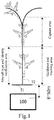
- Fig. 3 is a block diagram illustratively showing a structure of the laser scanning system.
- a housing 11 of the laser scanning system accommodates at least the laser ranging device 1, the horizontal laser scanning device 2 and the vertical laser scanning device 3.
- the housing 11 of the laser scanning system is provided with a laser emitting window 12, through which the laser from the horizontal laser scanning device 2 and the vertical laser scanning device 3 is emitted to scan an object to be guided.
- the laser emitting window 12 has a fixed position relative to the horizontal laser scanning device 2 and the vertical laser scanning device 3.
- a device mounting zero point calibration step needs to be performed so as to calibrate the zero point of the laser scanning system.
- the horizontal zero point position for the horizontal laser emitting direction of the horizontal laser scanning device 2 and the vertical zero point position for the vertical laser emitting direction of the vertical laser scanning device 3 need to be determined.
- Both the horizontal laser scanning device 2 and the vertical laser scanning device 3 are mounted at a height H from the ground.
- the vertical reflection mirror 32 maintains the initial vertical scanning angle ⁇ 0 unchanged, and the horizontal scanning stepper motor 21 drives the horizontal reflection mirror 22 to horizontally scan a front calibration area on the ground with a scanning angle of ⁇ 0 .
- the calibration area is usually in front of and below the horizontal laser scanning device 2, for example, the stopping line 71 as shown in Fig. 1 .
- the laser ranging device 1 obtains the distance values of individual points in the calibration area in real time.
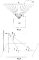
- Fig. 4 is a schematic diagram illustratively showing the principle of the horizontal zero point calibration.
- a minimum value D min is found among the N+1 distance values D n .
- an extended area D exe is determined. For example, with the boundary point corresponding to the minimum value D min as the center, by shifting a preset length or degree leftwards and rightwards, the extended area can be obtained.
- the purpose for determining the extended area is to determine an approximate range where the horizontal zero point might exist.
- the extended area is scanned again.
- the extended area can be divided more finely with the highest resolution, and distance measurement can be performed with respect to the divided boundary points, and a position of the horizontal reflection mirror corresponding to a minimum distance value can be identified as a horizontal zero point.
- the calibration of the vertical zero point can be realized by scanning for two times.
- the horizontal laser scanning device 2 maintains static at a zero angle
- the vertical laser scanning device 3 conducts distance measurement at a vertical scanning angle ⁇ 1 to obtain first distance value L 1 .
- the horizontal laser scanning device 2 still maintains static, and the vertical laser scanning device 3 conducts the distance measurement again by adjusting the vertical scanning angle upwards by an angle ⁇ , i.e., at a vertical scanning angle ⁇ 2 , to obtain a second distance value L 2 .
- the angles ⁇ 1 and ⁇ 2 are all angles of laser with respect to the horizontal line.
- Fig. 5 is a schematic diagram illustratively showing the principle of the vertical zero point calibration.
- the right-angled triangle with L 1 as its hypotenuse, and the right-angled triangle with L 2 as its hypotenuse share the same side, which indicates the height value of the laser scanning system from the horizontal ground.
- a position of the vertical reflection mirror when the vertical reflection mirror is rotated upwards by an angle ( ⁇ 1 - ⁇ ) with respect to the current position of the vertical reflection mirror can be identified as a vertical zero point.
- the above described is the calibration performed when the laser scanning-based aircraft docking guidance system 100 is mounted for the first time. Every time when the laser scanning system is repowered on, a zero correction step needs to be performed.
- both the horizontal scanning stepper motor 21 and the vertical canning stepper motor 31 may generate dithering (or vibrations).
- a reference object needs to be selected to re-calibrate the zero point for laser scanning.
- the boundary of the laser emitting window 12 may be selected as the reference object.
- the laser scanning system adjusts a scanning angle from a calibrated zero point step by step until a preset reference object is found, and records a scanning angle ( ⁇ r , ⁇ r ) at this time as a correction angle.
- the horizontal scanning stepper motor 21 and the vertical scanning stepper motor 31 starts from the calibrated zero point.
- a predetermined corner for example, the upper left corner
- the vertical reflection mirror gradually goes upwards from the initial angle, and horizontal scanning is performed for each vertical scanning angle, until a distance value consistent with a preset length is obtained at a certain vertical scanning angle, and the horizontal scanning angle at that time corresponds to the position where the upper left corner of the laser emitting window 12 is, i.e., the direction of the horizontal scanning angle is towards left.
- the vertical scanning angle ⁇ r and the horizontal scanning angle ⁇ r are recorded as the correction angle, and the correction angle can be hardened into a constant for recording.
- the horizontal scanning stepper motor 21 and the vertical scanning stepper motor 31 scan randomly until the preset reference object is found. Then, the scanning angles are adjusted backwards by the correction angle to find the calibrated zero point, so that subsequent capture, tracking and guidance procedure can have higher accuracy.
- a guidance line setting step may also be performed. Specific steps may be as follows.
- a calibration object is set up at two positions on the guidance line.
- the calibration object may be a person or a calibration board which is bigger than a person.
- One of the two positions is an intersection point (i.e., a stopping point) of the guidance line and a stopping line, and the other is a father position on the straight guidance line, which can be as far as possible, for example, 100 meters away.
- the calibration objects at the two positions are horizontally scanned for many times, and the points obtained by the scanning are converted into x-y-z three dimensional coordinates. Points, z coordinates of which are within a certain range, are extracted as the points obtained by the scanning of the calibration objects.
- the range is preferably from 0.5 meter to 1.5 meters.
- the laser scanning-based aircraft docking guidance system 100 starts to perform a capture step.
- the laser scanning-based aircraft docking guidance method in the present disclosure may generally include three steps: a capture step, a guidance step and a tracking step.
- laser scanning is conducted to horizontally scan a position where an aircraft head of an aircraft is expected to appear, pieces of echo data based on the laser scanning is obtained, and according to a judgment condition, whether the aircraft appears is determined based on the echo data.
- the laser scanning is conducted to horizontally scan the aircraft head, echo data based on the laser scanning is obtained, and a position of an aircraft nose of the aircraft is determined according to the echo data.
- the position of the aircraft nose is tracked by adjusting a vertical scanning angle of the laser scanning, the posture of the aircraft (including distance and deflection direction) is calculated according to the position of the aircraft nose, and is displayed in real time.
- the aircraft type or a particular aircraft which can be docked at the gate is designated in advance, and then the aircraft nose height h of an aircraft which should be docked can be known in advance.
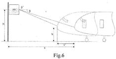
- the mounting height of the system 100 is H (i.e., the system 100 is mounted at a height of H ), and a distance from the system 100 to the farthest edge of the capture area is s according to the field definition.
- the laser scanning system horizontally scans a position where an aircraft head of an aircraft is expected to appear, obtains echo data based on the laser scanning, and according to a judgment condition, determines whether the aircraft appears based on the echo data.
- the head of an arriving aircraft is expected to appear at the farthest edge s of the capture area at a height h (i.e., the aircraft nose height).
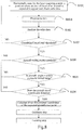
- Fig. 7 is a flow chart illustratively showing the capture step in the present disclosure.
- step 101 the laser scanning system horizontally scans a position where an aircraft head of an aircraft is expected to appear and obtains echo data.
- the laser scanning system continuously obtains data regarding the same row, especially the distance values of the same row. Before an aircraft appears, the data obtained by the laser scanning system may be wrong returned data which may exceed the farthest distance or may be results far greater than the edge distance.
- step 102 the echo data is analyzed.
- the points in the echo data which are within a certain range from dis_predict can be considered as points of interest.
- the points within the range of dis _ predict ⁇ 5 m can be considered as points of interest.
- the total number CountTotal of the points of interest in the data regarding one row obtained after one horizontal scan is calculated.
- the data regarding the row may include points of interest and points not of interest. Continuous points of interest in this row are found, and a plurality of strings of points of interest may be found. From the plurality of strings of points of interest, a string having the minimum data L min is identified. The point corresponding to the minimum data can be considered as the expected aircraft nose point. The total number of the points in the string having the minimum data L min is CountMin.
- step 103 whether CountMin / CountTotal is greater than a threshold is determine. If CountMin / CountTotal is greater than a threshold, step 104 is performed. If CountMin / CountTotal is not greater than a threshold, step 101 is performed.
- the threshold may be from 0.3 to 0.7, for example, 0.5.
- step 104 an aircraft width is calculated based on the total number of the pieces of echo data, and whether the aircraft width is not less than a width threshold is determined. If the aircraft width is not less than a width threshold, step 105 is performed. If the aircraft width is less than a width threshold, step 101 is performed.
- Each gate is assigned with a particular type of aircraft in advance, parameters of the aircraft of this type are known. Under such condition, further determination can be made according to the width of the aircraft which is actually being docked to identify whether the aircraft currently being docked meets the parameter requirements of the predefined type, and then whether the aircraft currently being docked is the particular type of aircraft assigned in advance can be determined.
- width _cal L min * sin CountTotal*R , where R is the rotation angle of a stepper motor for driving a reflection mirror to be rotated for each measurement.
- width is the aircraft width of the particular type of aircraft. If the aircraft width meets the above condition, step 105 is performed. If the aircraft width does not meet the above condition, step 101 is performed to conduct further scanning.
- step 105 an aircraft height z is calculated and whether the calculated aircraft height is within a predetermined range is determined. If the calculated aircraft height is within a predetermined range, step 106 is performed. If the calculated aircraft height is not within a predetermined range, step 101 is performed.
- the height data of the aircraft being docked is further determined in this step so as to accurately identify whether the aircraft currently being docked meets the parameter requirements of the predefined type of aircraft, and then whether the aircraft currently being docked is the particular type of aircraft assigned in advance can be determined.
- the aircraft height z is the aircraft nose height.
- w is a height threshold parameter, for example, w is equal to 0.5m.
- step 106 is further performed. If the aircraft height does not meet the above condition, step 101 is performed.
- step 106 whether the aircraft travels a particular distance is determined. If the aircraft does not travel a particular distance, step 101 is performed. If aircraft travels a particular distance, three dimensional coordinates of the expected aircraft nose point of the captured aircraft are calculated and then the subsequent guidance step and tracking step are performed.
- the particular distance may be 10 meters.
- repeated scanning and determinations are made while the aircraft travels 10 meters. If the aircraft is consistent with the particular aircraft type and travels beyond 10 meters, the three coordinates of the expected aircraft nose point of the aircraft are obtained. After an aircraft travels the particular distance, the aircraft enters the guidance area.
- another step 1011 may be further included between steps 101 and 102.
- a preprocess step when the echo data is obtained, median filtering is performed on the echo data and then whether the aircraft appears is determined.
- the preprocess step can be performed any time when echo data is received, and after the echo data is processed, subsequent step can be performed.
- the purpose for preprocessing data is to ensure the effectiveness and real time performance of data.
- the preprocess mainly include removal of random noise points and coordinate conversion of data points.
- ⁇ d is very small. Due to the existence of noise pints, assuming the value of the noise point is d j , the two differences ⁇ d between one noise point and its two neighboring points d j -1 and ⁇ d j +1 are relatively big.
- the main steps of the median filtering include:
- Fig. 9 is a flow chart illustratively showing the guidance step.
- the guidance step can include the following steps.
- step 201 after an aircraft enters into the guidance area, the expected aircraft nose point position is scanned at a predetermined vertical scanning angle to obtain echo data, target points falling on the aircraft head are extracted from the echo data, and the target points are converted from polar coordinate data into three-dimensional spatial data.
- the target points can be selected based on the same principles for selecting the points of interest as mentioned above.
- step 202 a point having a minimum Y-direction value is identified from the target points as a closest point (X d , Y d ).
- step 203 curve fitting is conducted to fit the target points to a curve and a vertex of the curve is identified.
- the values of a 0 , a 1 , and a 2 can be obtained.
- Matching of (x min ,y min ) against the set S of target points is conducted to identify a point which has X-axis and Y-axis coordinates which are the same as (x min ,y min ), and the three dimensional coordinates ( x n , y n , z n ) of the point can be formed using (x min ,y min ) and the Z-axis coordinate of the point.
- step 204 according to a difference between the value of X d of the closest point (X d , Y d ) and the value of X min of the vertex, one of the closest point and the vertex can be determined as the aircraft nose position.
- Whether ⁇ X is smaller than a preset threshold can be determined. If ⁇ X is not smaller than a preset threshold, (X 0 , Y 0 ) can be taken as the aircraft point. If ⁇ X is smaller than a preset threshold, the closest point (X d , Y d ) can be taken as the aircraft pose point. In this way, the aircraft nose point can be located accurately.
- the present threshold can be for example 50 centimeters.
- the deviation distance from the aircraft nose point to the guidance line and the remaining distance from the aircraft nose point to the stopping line can be calculated.
- step 205 the aircraft nose position is displayed on the information display unit 6.
- Fig. 10 is an aerial view during tracking of an aircraft
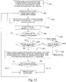
- Fig. 11 is a flow chart illustratively showing the tracking step.
- the tracking step may include the following steps.
- step 301 the position of the aircraft nose point is scanned at a predetermined vertical scanning angle ⁇ , and a vertical distance Y 10 from the aircraft nose point to the x axis at this time is recorded.
- step 302 as the aircraft travels forward, horizontal scanning is conducted with the current vertical scanning angle unchanged.
- step 303 the current aircraft nose point is found by a locating algorithm, a vertical distance Y 20 from the aircraft nose point to the x axis is recorded, and the current aircraft nose point is displayed on the information display unit 6 in real time.
- the locating algorithm can be as follows. When the horizontal scanning is conducted while maintaining the vertical scanning angle ⁇ , the aircraft is travelling forward, and the minimum distance value in the currently received echo data gradually decreases. The shape of the aircraft is fixed and the data about the shape of the aircraft is known, and then according to the received echo data and the known shape data of the particular type of aircraft, the specific position of the scanned aircraft when the horizontal scanning is conducted with the vertical scanning angle ⁇ unchanged. And, the position of the current aircraft nose point can be known by calculation according to the shape data of the particular type of aircraft.
- step 306 is performed. If Y 30 does not meet a given threshold requirement, step 302 is performed.
- the threshold When Y 10 is equal to or greater than 20 meters, the threshold is set as 5 meters. When Y 10 is smaller than 20 meters, the threshold is set as 1 meter. Whether Y 30 is smaller than the threshold is determined.
- step 306 whether the aircraft arrives at the stopping line is determined. If the aircraft has arrived at the stopping line, step 307 is performed.
- step 307 vertical scanning is conducted for once at the current aircraft nose point to obtain the contour of the aircraft, find the vertex of the parabola of the aircraft contour, and thereby calculate a variation amount ⁇ ' of the vertical scanning angle.
- the threshold may be ranging from 0.3 to 1 degree, for example, 0.5 degree.
- step 308 tracking is continued for a predetermined time period, and whether the aircraft is moving is determined.
- step 309 if the aircraft is moving, warning can be issued, and step 306 is performed. If the aircraft is not moving, the tracking can be stopped.
- the technical solutions in the present disclosure can adjust the vertical scanning angle at any time to find the actual position of the aircraft nose point at any time.
- tracking and display of the aircraft nose point are realized.
- the technical solutions in the present disclosure may further include an aircraft type identification step. If it is found in the aircraft identification step that the current aircraft is not consistent with the type of the aircrafts which should be docked in at a gate, corresponding verifications conditions are not met, and then waring information can be issued.
- the aircraft identification may include one or more of aircraft nose height verification, aircraft cabin width verification, verification of a head aerial view profile, verification of a head side view profile and aircraft engine verification.
- a higher safety level requires a stricter condition to verify whether the aircraft type and identity are right, and accordingly more time is needed.
- a corresponding verification level can be selected according to the length of guidance lines of aprons and the aircraft type.
- the position of the aircraft nose can be calculated according to the obtained positions and the relationship between relative positions of the aircraft nose and engines so as to locate the aircraft.
- the aircraft nose height verification can be performed as described above with respect to step 105.
- the aircraft cabin width verification can be performed as described above with respect to step 104.
- the aircraft engine verification may be as follows.
- step 41 positions of engines are calculated according to the position of the aircraft nose, and laser scanning is conducted to horizontally and vertically scan the positions of the engines.
- the coordinate differences between the aircraft nose and an engine center is ( ⁇ x n , ⁇ y n , ⁇ z n ) are known, and the obtained coordinates of the aircraft nose are ( x n , y n , z n ), the coordinates of a theoretic engine center are p egn ( x n + ⁇ x n , y n + ⁇ y n , z n + ⁇ z n ).
- step 42 the echo data obtained by the horizontal laser scanning is converted into x-y-z three dimensional coordinates, a closest coordinate point which is closest to the theoretic engine center is found, and points contiguous to the closest coordinate point are found to obtain a point set, and a distance between a leftmost point and a rightmost point in the point set is calculated as an engine width and a middle point between the leftmost point and the rightmost point is taken as a horizontal coordinate x egn of an engine center.
- step 43 the echo data obtained by the vertical laser scanning is converted into x-y-z three dimensional coordinates, a closest coordinate point which is closest to the theoretic engine center is found, and points contiguous to the closest coordinate point are found to obtain a point set, and a distance between a uppermost point and a lowermost point in the point set is calculated as an engine height, and a middle point between the uppermost point and the lowermost point is taken as a height z egb of the engine center from ground.
- step 44 if a pair of x egn and z egb can be found, it can be determined that an engine is found. By scanning different engines for a plurality of times, the number n egn of engines can be obtained.
- step 45 whether the number of the engines is consistent with a preset number is determined, and if the number of the engines is not consistent with the preset number, it can be determined that the aircraft engine verification is not passed.
- step 46 whether a difference between the horizontal coordinate of the engine center and a standard value exceeds a threshold or whether a difference between the height of the engine center from ground and a standard value exceeds a threshold (for example, 30 cm) is determined, and if the difference between the horizontal coordinate of the engine center and a standard value exceeds the threshold or the difference between the height of the engine center from ground and a standard value exceeds the threshold, it can be determined that the aircraft engine verification is not passed.
- a threshold for example, 30 cm
- step 47 whether a difference between the engine width and a standard value exceeds a threshold, or whether a difference between the engine height and a standard value exceeds a threshold (for example, 20cm), and if the difference between the engine width and a standard value exceeds the threshold, or the difference between the engine height and a standard value exceeds the threshold, it can be determined that the aircraft engine verification is not passed.
- a threshold for example, 20cm
- the technical solutions provided by embodiments of the present disclosure can capture, guide and track the aircrafts, obtain real time positions of aircrafts by accuracy laser scanning and display the positions so as to provide docking guidance to pilots. Further, technical solutions of the present disclosure can automatically identify types of aircrafts and thereby increase safety for aircraft docking.
Landscapes
- Engineering & Computer Science (AREA)
- Physics & Mathematics (AREA)
- General Physics & Mathematics (AREA)
- Electromagnetism (AREA)
- Radar, Positioning & Navigation (AREA)
- Remote Sensing (AREA)
- Computer Networks & Wireless Communication (AREA)
- Aviation & Aerospace Engineering (AREA)
- Mechanical Engineering (AREA)
- Optical Radar Systems And Details Thereof (AREA)
Claims (8)
- Laserscan-gestütztes Flugzeugandock-Führungsverfahren, umfassend:in einem Erfassungsschritt, Ausführen (101) eines Laser-Scans, um horizontal eine Position zu scannen, wo das Erscheinen eines Flugzeugbugs eines Flugzeugs erwartet wird, Erhalten von Teilen von Echodaten auf der Basis des Laser-Scans, und gemäß einer Beurteilungsbedingung, Bestimmen, ob das Flugzeug erscheint, auf der Basis der Echodaten;in einem Lokalisierungsschritt, nachdem das Flugzeug erschienen ist, Ausführen des Laser-Scans, um den Flugzeugbug horizontal zu scannen, Erhalten der Echodaten auf der Basis des Laser-Scans, und Bestimmen einer Position einer Flugzeugnase des Flugzeugs gemäß den Echodaten; undin einem Verfolgungs- und Führungsschritt, während das Flugzeug sich bewegt, Verfolgen der Position der Flugzeugnase durch Einstellen eines vertikalen Scan-Winkels des Laser-Scans, und Anzeigen der Position der Flugzeugnase in Echtzeit;dadurch gekennzeichnet, dass, vor dem Erfassungsschritt, das Verfahren des Weiteren einen Nullpunktkalibrierungsschritt umfasst, der einen Gerätemontage-Nullpunktkalibrierungsschritt umfasst, der ausgeführt wird, wenn ein Laser-Scan-System erstmals installiert wird, wobei der Gerätemontage-Nullpunktkalibrierungsschritt umfasst:einen horizontalen Nullpunkt-Messungsschritt, umfassend:horizontales Scannen, durch das Laser-Scan-System, eines Kalibrierungsbereichs am Boden mit einem festen vertikalen Scan-Winkel, wobei der Kalibrierungsbereich gleichmäßig in N kleine Regionen unterteilt ist; Messen von Entfernungen von einem Grenzpunkt einer jeden der kleinen Regionen, und Finden eines Mindestwert unter den erhaltenen Entfernungswerten; Bestimmen eines erweiterten Bereichs mit einem Grenzpunkt, der dem Mindestwert entspricht, als eine Mitte; und Identifizieren einer Position eines horizontalen Reflexionsspiegels (22), die einem Mindest-Entfernungswert entspricht, als einen horizontalen Nullpunkt; undeinen vertikalen Nullpunkt-Messungsschritt, umfassend:Ausführen einer Entfernungsmessung vom horizontalen Boden bei einem vertikalen Scan-Winkel β1 durch das Laser-Scan-System, um einen ersten Entfernungswert L1 zu erhalten, erneutes Ausführen der Entfernungsmessung durch Einstellen des vertikalen Scan-Winkels β1 aufwärts um einen Winkel λ, um einen zweiten Entfernungswert L2 zu erhalten, und Berechnen von β1 unter Verwendung der folgenden Gleichung:
 Drehen eines vertikalen Reflexionsspiegels (32) aufwärts um einen Winkel (β1-λ) mit Bezug auf die momentane Position des vertikalen Reflexionsspiegels (32), undIdentifizieren der resultierenden Position des vertikalen Reflexionsspiegels (32) als einen vertikalen Nullpunkt.
 - Verfahren nach Anspruch 1, dadurch gekennzeichnet, dass der Nullpunktkalibrierungsschritt des Weiteren einen Nullpunktkorrekturschritt umfasst, umfassend:nachdem der Gerätemontage-Nullpunktkalibrierungsschritt beendet ist, schrittweises Einstellen eines Scan-Winkels des Laser-Scan-Systems von einem Nullpunkt aus, bis ein voreingestelltes Referenzobjekt gefunden ist, und Aufzeichnen eines Scan-Winkels zu diesem Zeitpunkt als einen Korrekturwinkel; undwenn das Laser-Scan-System neu gestartet wird, Einstellen des Scan-Winkels rückwärts um den Korrekturwinkel, um den Nullpunkt zu finden, nachdem das voreingestellte Referenzobjekt durch das Laser-Scan-System gefunden ist.
- Verfahren nach Anspruch 1, dadurch gekennzeichnet, dass die Beurteilungsbedingung des Weiteren umfasst:A: Bestimmen, ob ein Verhältnis der Anzahl von interessierenden Punkten, die kontinuierlich sind und von denen einer einem Mindest-Entfernungswert entspricht, zur Gesamtzahl der Teile von Echodaten größer als eine Schwelle ist;B: Berechnen einer Flugzeugbreite auf der Basis der Gesamtzahl der Echodaten, und Bestimmen, ob die Flugzeugbreite nicht kleiner ist als eine Breitenschwelle; undC: Berechnen einer Flugzeughöhe, und Bestimmen, ob die berechnete Flugzeughöhe innerhalb eines zuvor festgelegten Bereichs liegt;wobei die Entfernungswerte der interessierenden Punkte innerhalb eines spezifizierten Vorhersagebereichs liegen.
- Verfahren nach Anspruch 1, dadurch gekennzeichnet, dass in dem Erfassungsschritt, wenn die Echodaten erhalten werden, eine Medianfilterung an den Echodaten ausgeführt wird, woraufhin bestimmt wird, ob das Flugzeug erscheint.
- Verfahren nach Anspruch 1, dadurch gekennzeichnet, dass der Lokalisierungsschritt des Weiteren umfasst:Extrahieren, aus den Echodaten, von Zielpunkten, die auf den Flugzeugbug fallen, und Konvertieren der Zielpunkte von polaren Koordinatendaten in dreidimensionale räumliche Daten;Identifizieren, aus den Zielpunkten, eines Punktes, der einen Mindest-Y-Richtungswert hat, als einen nächsten Punkt;Ausführen einer Kurvenanpassung, um die Zielpunkte an eine Kurve anzupassen und einen Scheitelpunkt der Kurve zu identifizieren; undBestimmen des nächsten Punktes oder des Scheitelpunktes als die Position der Flugzeugnase gemäß einer Differenz zwischen einem X-Wert des nächsten Punktes und einem X-Wert des Scheitelpunktes.
- Verfahren nach Anspruch 1, dadurch gekennzeichnet, dass der Verfolgungs- und Führungsschritt des Weiteren umfasst:Scannen der Position der Flugzeugnase bei einem zuvor festgelegten vertikalen Scan-Winkel, während sich das Flugzeug bewegt;Berechnen eines momentanen Flugzeugnasenpunktes gemäß den Echodaten; undvertikales Scannen des momentanen Flugzeugnasenpunktes, und Berechnen eines Variationsbetrages des vertikalen Scan-Winkels gemäß einem Scheitelpunkt einer erhaltenen Parabel gemäß dem Scannen, und Ändern des vertikalen Scan-Winkels gemäß dem Variationsbetrag, oder Berechnen des Variationsbetrages des vertikalen Scan-Winkels gemäß dem momentanen Flugzeugnasenpunkt und Ändern des vertikalen Scan-Winkels gemäß dem Variationsbetrag.
- Verfahren nach Anspruch 1, dadurch gekennzeichnet, dass das Verfahren des Weiteren einen Flugzeugtyp-Identifizierungsschritt umfasst;
wobei der Flugzeugtyp-Identifizierungsschritt eines oder mehrere von Folgendem umfasst: Flugzeugnasehöhenverifizierung, Flugzeugkabinenbreitenverifizierung, Verifizierung eines Bugprofils von oben, Verifizierung eines Bugprofils von der Seite, und Flugzeugtriebwerksverifizierung;
wobei die Flugzeugnasehöhenverifizierung umfasst: wenn eine Differenz zwischen der Flugzeugnasehöhe und einer voreingestellten Flugzeugnasehöhe innerhalb eines voreingestelltes Bereichs liegt, Bestimmen, dass die Flugzeugnasehöhenverifizierung bestanden wurde;
die Flugzeugkabinenbreitenverifizierung umfasst: Finden zweier Punkte aus den Echodaten, bei denen eine Differenz zwischen X-Koordinaten das Maximum ist, mit einer geradlinigen Entfernung zwischen den zwei Punkten als eine Flugzeugkabinenbreite, wenn die Flugzeugkabinenbreite größer ist als ein Produkt einer theoretischen Flugzeugkabinenbreite und eines Breitenkoeffizienten, Bestimmen, dass die Flugzeugkabinenbreitenverifizierung bestanden wurde;
die Verifizierung des Bugprofils von oben umfasst: Einbringen der Echodaten (xi,yi,zi), die durch horizontales Laser-Scannen erhalten wurden, in eine voreingestellte Draufsichtprofilgleichung y = fn (x), Berechnen eines horizontalen Anpasspunktfehlers

die Verifizierung des Bugprofils von der Seite umfasst: Einbringen der Echodaten (xi,yi,zi), die durch vertikales Laser-Scannen erhalten wurden, in eine voreingestellte Seitenansichtsprofilgleichung z = gm (y), Berechnen eines vertikalen Anpasspunktfehlers

die Flugzeugtriebwerksverifizierung umfasst:Berechnen von Positionen von Triebwerken gemäß der Position der Flugzeugnase, und Ausführen von Laser-Scans, um die Positionen der Triebwerke horizontal und vertikal zu scannen;Konvertieren der Echodaten, die durch das horizontale Scannen erhalten wurden, in dreidimensionale x-y-z-Koordinaten, Finden eines nächsten Koordinatenpunktes, der einer theoretischen Triebwerksmitte am nächsten liegt, und Finden von Punkten, die an den nächsten Koordinatenpunkt angrenzen, um einen Punktsatz zu erhalten, und Berechnen einer Entfernung zwischen einem äußerst linken Punkt und einem äußerst rechten Punkt in dem Punktsatz als eine Triebwerksbreite und eines Mittelpunktes zwischen dem äußerst linken Punkt und dem äußerst rechten Punkt als eine horizontale Koordinate einer Triebwerksmitte;Konvertieren der Echodaten, die durch das vertikale Scannen erhalten wurden, in dreidimensionale x-y-z-Koordinaten, Finden eines nächsten Koordinatenpunktes, der der theoretischen Triebwerksmitte am nächsten liegt, und Finden von Punkten, die an den nächsten Koordinatenpunkt angrenzen, um einen Punktsatz zu erhalten, und Berechnen einer Entfernung zwischen einem höchsten Punkt und einem tiefsten Punkt in dem Punktsatz als eine Triebwerkhöhe und eines Mittelpunktes zwischen dem höchsten Punkt und dem tiefsten Punkt als eine Höhe der Triebwerksmitte vom Boden;Bestimmen, ob die Anzahl der Triebwerke mit einer voreingestellten Anzahl übereinstimmt, und wenn die Anzahl der Triebwerke nicht mit der voreingestellten Anzahl übereinstimmt, Bestimmen, dass die Flugzeugtriebwerksverifizierung nicht bestanden wurde;Bestimmen, ob eine Differenz zwischen der horizontalen Koordinate der Triebwerksmitte und einem Standardwert eine Schwelle überschreitet oder ob eine Differenz zwischen der Höhe der Triebwerksmitte vom Boden und einem Standardwert eine Schwelle überschreitet, und wenn die Differenz zwischen der horizontalen Koordinate der Triebwerksmitte und einem Standardwert eine Schwelle überschreitet oder die Differenz zwischen der Höhe der Triebwerksmitte vom Boden und einem Standardwert eine Schwelle überschreitet, Bestimmen, dass die Flugzeugtriebwerksverifizierung nicht bestanden wurde;Bestimmen, ob eine Differenz zwischen der Triebwerksbreite und einem Standardwert eine Schwelle überschreitet oder ob eine Differenz zwischen der Triebwerkshöhe und einem Standardwert eine Schwelle überschreitet, und wenn die Differenz zwischen der Triebwerksbreite und einem Standardwert eine Schwelle überschreitet, oder die Differenz zwischen der Triebwerkshöhe und einem Standardwert eine Schwelle überschreitet, Bestimmen, dass die Flugzeugtriebwerksverifizierung nicht bestanden wurde. - Laserscan-gestütztes Flugzeugandock-Führungssystem (100), umfassend:ein Laser-Scan-System (1, 2, 3), das einen horizontalen Reflexionsspiegel (22) und einen vertikalen Reflexionsspiegel (32) umfasst,eine Informationsverarbeitungseinheit (5), und eine Informationsanzeigeeinheit (6), dadurch gekennzeichnet, dassdas Laserscan-gestützte Flugzeugandock-Führungssystem (100) dafür ausgestaltet ist, die Schritte des Verfahrens nach einem der Ansprüche 1 bis 7 auszuführen.
Applications Claiming Priority (2)
| Application Number | Priority Date | Filing Date | Title |
|---|---|---|---|
| CN201410377385.3A CN105329457B (zh) | 2014-08-01 | 2014-08-01 | 一种基于激光扫描的飞机入坞引导系统及方法 |
| PCT/CN2015/083204 WO2016015545A1 (zh) | 2014-08-01 | 2015-07-02 | 一种飞机入坞引导和机型识别的系统及方法 |
Publications (3)
| Publication Number | Publication Date |
|---|---|
| EP3196128A1 EP3196128A1 (de) | 2017-07-26 |
| EP3196128A4 EP3196128A4 (de) | 2017-12-20 |
| EP3196128B1 true EP3196128B1 (de) | 2019-04-10 |
Family
ID=55216747
Family Applications (1)
| Application Number | Title | Priority Date | Filing Date |
|---|---|---|---|
| EP15827108.0A Active EP3196128B1 (de) | 2014-08-01 | 2015-07-02 | System und verfahren zur flugzeugandockführung und zur flugzeugtypidentifizierung |
Country Status (4)
| Country | Link |
|---|---|
| US (1) | US10562644B2 (de) |
| EP (1) | EP3196128B1 (de) |
| CN (1) | CN105329457B (de) |
| WO (1) | WO2016015545A1 (de) |
Families Citing this family (17)
| Publication number | Priority date | Publication date | Assignee | Title |
|---|---|---|---|---|
| ES2748042T3 (es) * | 2016-03-21 | 2020-03-12 | Adb Safegate Sweden Ab | Optimización del alcance de un sistema de atraque de aeronaves |
| CN107885223B (zh) * | 2017-10-31 | 2020-02-14 | 武汉大学 | 基于激光的无人机回收引导系统 |
| CN107976296B (zh) * | 2017-11-13 | 2019-10-22 | 北京临近空间飞行器系统工程研究所 | 一种基于回溯自适应算法的飞行器气动特性在线辨识方法 |
| CN109143249A (zh) * | 2018-09-04 | 2019-01-04 | 北京大汉正源科技有限公司 | 一种激光雷达发射控制方法及控制系统 |
| CN109709566A (zh) * | 2018-12-25 | 2019-05-03 | 中国科学院半导体研究所 | 曲面地形障碍物监测的装置 |
| TN2021000005A1 (en) * | 2019-05-22 | 2022-10-03 | Tamer Akcay Ve Ortaklari Bilisim Sistemleri Kollektif Sirketi | Innovation in burning method for laser marking machines |
| CN110579771A (zh) * | 2019-09-12 | 2019-12-17 | 南京莱斯信息技术股份有限公司 | 一种基于激光点云的飞机泊位引导方法 |
| CN111891379B (zh) * | 2020-06-28 | 2022-10-14 | 南京工程学院 | 一种基于干涉预分析的航空发动机稳健调姿安装方法 |
| CN111949022B (zh) * | 2020-07-30 | 2021-06-29 | 深圳煜炜光学科技有限公司 | 一种自动对位桥吊的智能导引搬运车及使用方法 |
| CN112357110B (zh) * | 2020-09-22 | 2022-04-08 | 成都飞机工业(集团)有限责任公司 | 基于激光定位原理的飞机滑行灯安装角度校准系统及方法 |
| CN112711266B (zh) * | 2020-12-03 | 2023-03-31 | 中国科学院光电技术研究所 | 一种月球轨道交会对接激光雷达的远近场切换控制方法 |
| CN114910880B (zh) * | 2021-02-08 | 2025-02-07 | 宁波方太厨具有限公司 | 一种清洁机器人识别基站位置的方法 |
| KR102567249B1 (ko) * | 2021-04-21 | 2023-08-21 | (주)안세기술 | 3차원 레이저 스캐너를 이용한 항공기 주기유도 시스템 및 이를 이용한 항공기 주기 제어방법 |
| CN113706930B (zh) * | 2021-09-01 | 2022-09-09 | 浙江华是科技股份有限公司 | 一种桥区引航方法、装置、系统及计算机存储介质 |
| CN115243022B (zh) * | 2022-08-22 | 2024-03-05 | 周口师范学院 | 一种激光投影互动展示系统 |
| CN116258765B (zh) * | 2023-05-11 | 2023-08-01 | 中航成飞民用飞机有限责任公司 | 一种飞机货舱门引导锁内腔廓线的确定方法及装置 |
| CN119781336B (zh) * | 2024-12-19 | 2025-09-19 | 江苏沙钢钢铁有限公司 | 一种基于激光测距的精炼回转台自动控制系统 |
Family Cites Families (18)
| Publication number | Priority date | Publication date | Assignee | Title |
|---|---|---|---|---|
| JP2523633B2 (ja) * | 1987-05-13 | 1996-08-14 | 株式会社日立製作所 | レ−ザレ−ダの走査方法 |
| JPH02216393A (ja) | 1989-02-15 | 1990-08-29 | Toshiba Tesuko Kk | 航空機ドッキングガイダンス装置 |
| US6324489B1 (en) * | 1999-10-29 | 2001-11-27 | Safegate International Ab | Aircraft identification and docking guidance systems |
| DE4301637C2 (de) * | 1993-01-22 | 1997-05-22 | Daimler Benz Aerospace Ag | Verfahren zum Andocken eines Flugzeuges an eine Fluggastbrücke eines Flughafengebäudes |
| US5334848A (en) | 1993-04-09 | 1994-08-02 | Trw Inc. | Spacecraft docking sensor system |
| BR9408629A (pt) * | 1994-10-14 | 1998-12-01 | Airport Tech Scandinavia | Sistema e processo para verificar a forma de um objeto detectado e sistema para rastrear um objeto |
| CN1053512C (zh) | 1994-10-14 | 2000-06-14 | 斯堪的纳维亚空港技术公司 | 飞机识别及入坞引导系统 |
| US5982299A (en) * | 1995-08-11 | 1999-11-09 | Cafaro Laser, Ltd. | Laser based visual landing aids and method for implementing same |
| US5675661A (en) * | 1995-10-12 | 1997-10-07 | Northrop Grumman Corporation | Aircraft docking system |
| US6563432B1 (en) | 2001-01-12 | 2003-05-13 | Safegate International Ab | Aircraft docking system and method with automatic checking of apron and detection of fog or snow |
| US6658329B1 (en) * | 2002-05-02 | 2003-12-02 | The United States Of America As Represented By The United States National Aeronautics And Space Administration | Video guidance sensor system with laser rangefinder |
| SE520914E (sv) * | 2002-06-11 | 2010-05-18 | Fmt Int Trade Ab | Förfarande för beröringsfri mätning av avstånd och läge till flygplan vid dockning, jämte anordning härför |
| US6910660B2 (en) * | 2003-01-31 | 2005-06-28 | The Boeing Company | Laser guidance system |
| US7481537B2 (en) | 2006-03-13 | 2009-01-27 | Beyond Vr, Llc | Method for creating kaleidoscopic interfaces for use in biofeedback |
| WO2013141605A1 (ko) | 2012-03-21 | 2013-09-26 | (주)안세기술 | 항공기의 기종판별 및 주기유도를 위한 시스템 및 방법 |
| CN203601576U (zh) | 2013-07-04 | 2014-05-21 | 爱乐基股份有限公司 | 航空器进场导引系统 |
| US9177483B2 (en) * | 2013-11-20 | 2015-11-03 | Unibase Information Corp. | Guiding method for aircraft docking process |
| CN103786893B (zh) | 2014-01-24 | 2016-05-04 | 中国民用航空总局第二研究所 | 一种基于激光测距技术的飞机泊位自动引导方法及装置 |
-
2014
- 2014-08-01 CN CN201410377385.3A patent/CN105329457B/zh active Active
-
2015
- 2015-07-02 EP EP15827108.0A patent/EP3196128B1/de active Active
- 2015-07-02 WO PCT/CN2015/083204 patent/WO2016015545A1/zh not_active Ceased
- 2015-07-02 US US15/329,979 patent/US10562644B2/en active Active
Also Published As
| Publication number | Publication date |
|---|---|
| WO2016015545A1 (zh) | 2016-02-04 |
| US20170259939A1 (en) | 2017-09-14 |
| CN105329457B (zh) | 2017-09-22 |
| EP3196128A1 (de) | 2017-07-26 |
| US10562644B2 (en) | 2020-02-18 |
| CN105329457A (zh) | 2016-02-17 |
| EP3196128A4 (de) | 2017-12-20 |
Similar Documents
| Publication | Publication Date | Title |
|---|---|---|
| EP3196128B1 (de) | System und verfahren zur flugzeugandockführung und zur flugzeugtypidentifizierung | |
| EP3196863B1 (de) | System und verfahren zur flugzeugandockführung und zur flugzeugtypidentifizierung | |
| JP5705484B2 (ja) | 飛行機の識別及びドッキング誘導装置 | |
| JP4080880B2 (ja) | 航空機ドック入れシステムならびにエプロンの自動検査および霧または雪の検出を伴う方法 | |
| US9177483B2 (en) | Guiding method for aircraft docking process | |
| US10444398B2 (en) | Method of processing 3D sensor data to provide terrain segmentation | |
| US9014956B2 (en) | Distance determination and type of aircraft determination during docking at the gate | |
| CN105336221B (zh) | 一种入坞飞机实时捕获方法及系统 | |
| CN104443423B (zh) | 航空器进场引导系统的校正定位方法 | |
| CN105438493B (zh) | 一种基于激光扫描的飞机入坞跟踪定位系统及方法 | |
| SE520914C2 (sv) | Förfarande för beröringsfri mätning av avstånd och läge till flygplan vid dockning, jämte anordning härför | |
| TWI539412B (zh) | 航空器進場導引系統的校正定位方法 |
Legal Events
| Date | Code | Title | Description |
|---|---|---|---|
| STAA | Information on the status of an ep patent application or granted ep patent |
Free format text: STATUS: THE INTERNATIONAL PUBLICATION HAS BEEN MADE |
|
| PUAI | Public reference made under article 153(3) epc to a published international application that has entered the european phase |
Free format text: ORIGINAL CODE: 0009012 |
|
| STAA | Information on the status of an ep patent application or granted ep patent |
Free format text: STATUS: REQUEST FOR EXAMINATION WAS MADE |
|
| 17P | Request for examination filed |
Effective date: 20170301 |
|
| AK | Designated contracting states |
Kind code of ref document: A1 Designated state(s): AL AT BE BG CH CY CZ DE DK EE ES FI FR GB GR HR HU IE IS IT LI LT LU LV MC MK MT NL NO PL PT RO RS SE SI SK SM TR |
|
| AX | Request for extension of the european patent |
Extension state: BA ME |
|
| DAV | Request for validation of the european patent (deleted) | ||
| DAX | Request for extension of the european patent (deleted) | ||
| A4 | Supplementary search report drawn up and despatched |
Effective date: 20171120 |
|
| RIC1 | Information provided on ipc code assigned before grant |
Ipc: G08G 5/06 20060101ALI20171114BHEP Ipc: G01S 17/06 20060101ALI20171114BHEP Ipc: B64D 45/08 20060101ALN20171114BHEP Ipc: G01S 17/93 20060101ALI20171114BHEP Ipc: B64F 1/00 20060101AFI20171114BHEP |
|
| RAP1 | Party data changed (applicant data changed or rights of an application transferred) |
Owner name: CHINA INTERNATIONAL MARINE CONTAINERS (GROUP) LTD. Owner name: SHENZHEN CIMC-TIANDA AIRPORT SUPPORT LTD. |
|
| REG | Reference to a national code |
Ref country code: DE Ref legal event code: R079 Ref document number: 602015028230 Country of ref document: DE Free format text: PREVIOUS MAIN CLASS: B64D0045080000 Ipc: B64F0001000000 |
|
| GRAP | Despatch of communication of intention to grant a patent |
Free format text: ORIGINAL CODE: EPIDOSNIGR1 |
|
| STAA | Information on the status of an ep patent application or granted ep patent |
Free format text: STATUS: GRANT OF PATENT IS INTENDED |
|
| RIC1 | Information provided on ipc code assigned before grant |
Ipc: B64F 1/00 20060101AFI20180920BHEP Ipc: G01S 17/93 20060101ALI20180920BHEP Ipc: G01S 17/06 20060101ALI20180920BHEP Ipc: G08G 5/06 20060101ALI20180920BHEP Ipc: B64D 45/08 20060101ALN20180920BHEP |
|
| INTG | Intention to grant announced |
Effective date: 20181023 |
|
| GRAS | Grant fee paid |
Free format text: ORIGINAL CODE: EPIDOSNIGR3 |
|
| GRAA | (expected) grant |
Free format text: ORIGINAL CODE: 0009210 |
|
| STAA | Information on the status of an ep patent application or granted ep patent |
Free format text: STATUS: THE PATENT HAS BEEN GRANTED |
|
| AK | Designated contracting states |
Kind code of ref document: B1 Designated state(s): AL AT BE BG CH CY CZ DE DK EE ES FI FR GB GR HR HU IE IS IT LI LT LU LV MC MK MT NL NO PL PT RO RS SE SI SK SM TR |
|
| REG | Reference to a national code |
Ref country code: GB Ref legal event code: FG4D |
|
| REG | Reference to a national code |
Ref country code: AT Ref legal event code: REF Ref document number: 1118328 Country of ref document: AT Kind code of ref document: T Effective date: 20190415 Ref country code: CH Ref legal event code: EP |
|
| REG | Reference to a national code |
Ref country code: IE Ref legal event code: FG4D |
|
| REG | Reference to a national code |
Ref country code: DE Ref legal event code: R096 Ref document number: 602015028230 Country of ref document: DE |
|
| REG | Reference to a national code |
Ref country code: NL Ref legal event code: FP |
|
| REG | Reference to a national code |
Ref country code: LT Ref legal event code: MG4D |
|
| REG | Reference to a national code |
Ref country code: AT Ref legal event code: MK05 Ref document number: 1118328 Country of ref document: AT Kind code of ref document: T Effective date: 20190410 |
|
| PG25 | Lapsed in a contracting state [announced via postgrant information from national office to epo] |
Ref country code: AL Free format text: LAPSE BECAUSE OF FAILURE TO SUBMIT A TRANSLATION OF THE DESCRIPTION OR TO PAY THE FEE WITHIN THE PRESCRIBED TIME-LIMIT Effective date: 20190410 Ref country code: FI Free format text: LAPSE BECAUSE OF FAILURE TO SUBMIT A TRANSLATION OF THE DESCRIPTION OR TO PAY THE FEE WITHIN THE PRESCRIBED TIME-LIMIT Effective date: 20190410 Ref country code: NO Free format text: LAPSE BECAUSE OF FAILURE TO SUBMIT A TRANSLATION OF THE DESCRIPTION OR TO PAY THE FEE WITHIN THE PRESCRIBED TIME-LIMIT Effective date: 20190710 Ref country code: SE Free format text: LAPSE BECAUSE OF FAILURE TO SUBMIT A TRANSLATION OF THE DESCRIPTION OR TO PAY THE FEE WITHIN THE PRESCRIBED TIME-LIMIT Effective date: 20190410 Ref country code: ES Free format text: LAPSE BECAUSE OF FAILURE TO SUBMIT A TRANSLATION OF THE DESCRIPTION OR TO PAY THE FEE WITHIN THE PRESCRIBED TIME-LIMIT Effective date: 20190410 Ref country code: HR Free format text: LAPSE BECAUSE OF FAILURE TO SUBMIT A TRANSLATION OF THE DESCRIPTION OR TO PAY THE FEE WITHIN THE PRESCRIBED TIME-LIMIT Effective date: 20190410 Ref country code: LT Free format text: LAPSE BECAUSE OF FAILURE TO SUBMIT A TRANSLATION OF THE DESCRIPTION OR TO PAY THE FEE WITHIN THE PRESCRIBED TIME-LIMIT Effective date: 20190410 Ref country code: PT Free format text: LAPSE BECAUSE OF FAILURE TO SUBMIT A TRANSLATION OF THE DESCRIPTION OR TO PAY THE FEE WITHIN THE PRESCRIBED TIME-LIMIT Effective date: 20190910 |
|
| PG25 | Lapsed in a contracting state [announced via postgrant information from national office to epo] |
Ref country code: RS Free format text: LAPSE BECAUSE OF FAILURE TO SUBMIT A TRANSLATION OF THE DESCRIPTION OR TO PAY THE FEE WITHIN THE PRESCRIBED TIME-LIMIT Effective date: 20190410 Ref country code: LV Free format text: LAPSE BECAUSE OF FAILURE TO SUBMIT A TRANSLATION OF THE DESCRIPTION OR TO PAY THE FEE WITHIN THE PRESCRIBED TIME-LIMIT Effective date: 20190410 Ref country code: GR Free format text: LAPSE BECAUSE OF FAILURE TO SUBMIT A TRANSLATION OF THE DESCRIPTION OR TO PAY THE FEE WITHIN THE PRESCRIBED TIME-LIMIT Effective date: 20190711 Ref country code: PL Free format text: LAPSE BECAUSE OF FAILURE TO SUBMIT A TRANSLATION OF THE DESCRIPTION OR TO PAY THE FEE WITHIN THE PRESCRIBED TIME-LIMIT Effective date: 20190410 Ref country code: BG Free format text: LAPSE BECAUSE OF FAILURE TO SUBMIT A TRANSLATION OF THE DESCRIPTION OR TO PAY THE FEE WITHIN THE PRESCRIBED TIME-LIMIT Effective date: 20190710 |
|
| PG25 | Lapsed in a contracting state [announced via postgrant information from national office to epo] |
Ref country code: IS Free format text: LAPSE BECAUSE OF FAILURE TO SUBMIT A TRANSLATION OF THE DESCRIPTION OR TO PAY THE FEE WITHIN THE PRESCRIBED TIME-LIMIT Effective date: 20190810 Ref country code: AT Free format text: LAPSE BECAUSE OF FAILURE TO SUBMIT A TRANSLATION OF THE DESCRIPTION OR TO PAY THE FEE WITHIN THE PRESCRIBED TIME-LIMIT Effective date: 20190410 |
|
| REG | Reference to a national code |
Ref country code: DE Ref legal event code: R097 Ref document number: 602015028230 Country of ref document: DE |
|
| PG25 | Lapsed in a contracting state [announced via postgrant information from national office to epo] |
Ref country code: EE Free format text: LAPSE BECAUSE OF FAILURE TO SUBMIT A TRANSLATION OF THE DESCRIPTION OR TO PAY THE FEE WITHIN THE PRESCRIBED TIME-LIMIT Effective date: 20190410 Ref country code: DK Free format text: LAPSE BECAUSE OF FAILURE TO SUBMIT A TRANSLATION OF THE DESCRIPTION OR TO PAY THE FEE WITHIN THE PRESCRIBED TIME-LIMIT Effective date: 20190410 Ref country code: CZ Free format text: LAPSE BECAUSE OF FAILURE TO SUBMIT A TRANSLATION OF THE DESCRIPTION OR TO PAY THE FEE WITHIN THE PRESCRIBED TIME-LIMIT Effective date: 20190410 Ref country code: RO Free format text: LAPSE BECAUSE OF FAILURE TO SUBMIT A TRANSLATION OF THE DESCRIPTION OR TO PAY THE FEE WITHIN THE PRESCRIBED TIME-LIMIT Effective date: 20190410 Ref country code: SK Free format text: LAPSE BECAUSE OF FAILURE TO SUBMIT A TRANSLATION OF THE DESCRIPTION OR TO PAY THE FEE WITHIN THE PRESCRIBED TIME-LIMIT Effective date: 20190410 |
|
| PLBE | No opposition filed within time limit |
Free format text: ORIGINAL CODE: 0009261 |
|
| STAA | Information on the status of an ep patent application or granted ep patent |
Free format text: STATUS: NO OPPOSITION FILED WITHIN TIME LIMIT |
|
| PG25 | Lapsed in a contracting state [announced via postgrant information from national office to epo] |
Ref country code: IT Free format text: LAPSE BECAUSE OF FAILURE TO SUBMIT A TRANSLATION OF THE DESCRIPTION OR TO PAY THE FEE WITHIN THE PRESCRIBED TIME-LIMIT Effective date: 20190410 Ref country code: MC Free format text: LAPSE BECAUSE OF FAILURE TO SUBMIT A TRANSLATION OF THE DESCRIPTION OR TO PAY THE FEE WITHIN THE PRESCRIBED TIME-LIMIT Effective date: 20190410 Ref country code: SM Free format text: LAPSE BECAUSE OF FAILURE TO SUBMIT A TRANSLATION OF THE DESCRIPTION OR TO PAY THE FEE WITHIN THE PRESCRIBED TIME-LIMIT Effective date: 20190410 |
|
| REG | Reference to a national code |
Ref country code: CH Ref legal event code: PL |
|
| 26N | No opposition filed |
Effective date: 20200113 |
|
| GBPC | Gb: european patent ceased through non-payment of renewal fee |
Effective date: 20190710 |
|
| PG25 | Lapsed in a contracting state [announced via postgrant information from national office to epo] |
Ref country code: TR Free format text: LAPSE BECAUSE OF FAILURE TO SUBMIT A TRANSLATION OF THE DESCRIPTION OR TO PAY THE FEE WITHIN THE PRESCRIBED TIME-LIMIT Effective date: 20190410 |
|
| REG | Reference to a national code |
Ref country code: BE Ref legal event code: MM Effective date: 20190731 |
|
| PG25 | Lapsed in a contracting state [announced via postgrant information from national office to epo] |
Ref country code: GB Free format text: LAPSE BECAUSE OF NON-PAYMENT OF DUE FEES Effective date: 20190710 |
|
| PG25 | Lapsed in a contracting state [announced via postgrant information from national office to epo] |
Ref country code: BE Free format text: LAPSE BECAUSE OF NON-PAYMENT OF DUE FEES Effective date: 20190731 Ref country code: LU Free format text: LAPSE BECAUSE OF NON-PAYMENT OF DUE FEES Effective date: 20190702 Ref country code: SI Free format text: LAPSE BECAUSE OF FAILURE TO SUBMIT A TRANSLATION OF THE DESCRIPTION OR TO PAY THE FEE WITHIN THE PRESCRIBED TIME-LIMIT Effective date: 20190410 Ref country code: CH Free format text: LAPSE BECAUSE OF NON-PAYMENT OF DUE FEES Effective date: 20190731 Ref country code: LI Free format text: LAPSE BECAUSE OF NON-PAYMENT OF DUE FEES Effective date: 20190731 |
|
| PG25 | Lapsed in a contracting state [announced via postgrant information from national office to epo] |
Ref country code: IE Free format text: LAPSE BECAUSE OF NON-PAYMENT OF DUE FEES Effective date: 20190702 |
|
| PG25 | Lapsed in a contracting state [announced via postgrant information from national office to epo] |
Ref country code: CY Free format text: LAPSE BECAUSE OF FAILURE TO SUBMIT A TRANSLATION OF THE DESCRIPTION OR TO PAY THE FEE WITHIN THE PRESCRIBED TIME-LIMIT Effective date: 20190410 |
|
| REG | Reference to a national code |
Ref country code: DE Ref legal event code: R082 Ref document number: 602015028230 Country of ref document: DE Representative=s name: GLEISS GROSSE SCHRELL UND PARTNER MBB PATENTAN, DE Ref country code: DE Ref legal event code: R081 Ref document number: 602015028230 Country of ref document: DE Owner name: SHENZHEN CIMC-TIANDA AIRPORT SUPPORT LTD., SHE, CN Free format text: FORMER OWNERS: CHINA INTERNATIONAL MARINE CONTAINERS (GROUP) LTD., SHENZHEN, GUANGDONG, CN; SHENZHEN CIMC-TIANDA AIRPORT SUPPORT LTD., SHENZHEN, GUANGDONG, CN |
|
| PG25 | Lapsed in a contracting state [announced via postgrant information from national office to epo] |
Ref country code: MT Free format text: LAPSE BECAUSE OF FAILURE TO SUBMIT A TRANSLATION OF THE DESCRIPTION OR TO PAY THE FEE WITHIN THE PRESCRIBED TIME-LIMIT Effective date: 20190410 Ref country code: HU Free format text: LAPSE BECAUSE OF FAILURE TO SUBMIT A TRANSLATION OF THE DESCRIPTION OR TO PAY THE FEE WITHIN THE PRESCRIBED TIME-LIMIT; INVALID AB INITIO Effective date: 20150702 |
|
| REG | Reference to a national code |
Ref country code: NL Ref legal event code: PD Owner name: SHENZHEN CIMC-TIANDA AIRPORT SUPPORT LTD.; CN Free format text: DETAILS ASSIGNMENT: CHANGE OF OWNER(S), ASSIGNMENT; FORMER OWNER NAME: SHENZHEN CIMC-TIANDA AIRPORT SUPPORT LTD. Effective date: 20211001 |
|
| PG25 | Lapsed in a contracting state [announced via postgrant information from national office to epo] |
Ref country code: MK Free format text: LAPSE BECAUSE OF FAILURE TO SUBMIT A TRANSLATION OF THE DESCRIPTION OR TO PAY THE FEE WITHIN THE PRESCRIBED TIME-LIMIT Effective date: 20190410 |
|
| PGFP | Annual fee paid to national office [announced via postgrant information from national office to epo] |
Ref country code: NL Payment date: 20250709 Year of fee payment: 11 |
|
| PGFP | Annual fee paid to national office [announced via postgrant information from national office to epo] |
Ref country code: DE Payment date: 20250722 Year of fee payment: 11 |
|
| PGFP | Annual fee paid to national office [announced via postgrant information from national office to epo] |
Ref country code: FR Payment date: 20250709 Year of fee payment: 11 |