EP3196423A1 - Statorhitzeschild für eine gasturbine, zugehörige gasturbine und verfahren zur kühlung - Google Patents
Statorhitzeschild für eine gasturbine, zugehörige gasturbine und verfahren zur kühlung Download PDFInfo
- Publication number
- EP3196423A1 EP3196423A1 EP17153154.4A EP17153154A EP3196423A1 EP 3196423 A1 EP3196423 A1 EP 3196423A1 EP 17153154 A EP17153154 A EP 17153154A EP 3196423 A1 EP3196423 A1 EP 3196423A1
- Authority
- EP
- European Patent Office
- Prior art keywords
- cooling channels
- heat shield
- stator heat
- cooling
- cavity
- Prior art date
- Legal status (The legal status is an assumption and is not a legal conclusion. Google has not performed a legal analysis and makes no representation as to the accuracy of the status listed.)
- Granted
Links
Images
Classifications
-
- F—MECHANICAL ENGINEERING; LIGHTING; HEATING; WEAPONS; BLASTING
- F01—MACHINES OR ENGINES IN GENERAL; ENGINE PLANTS IN GENERAL; STEAM ENGINES
- F01D—NON-POSITIVE DISPLACEMENT MACHINES OR ENGINES, e.g. STEAM TURBINES
- F01D11/00—Preventing or minimising internal leakage of working-fluid, e.g. between stages
- F01D11/08—Preventing or minimising internal leakage of working-fluid, e.g. between stages for sealing space between rotor blade tips and stator
-
- F—MECHANICAL ENGINEERING; LIGHTING; HEATING; WEAPONS; BLASTING
- F01—MACHINES OR ENGINES IN GENERAL; ENGINE PLANTS IN GENERAL; STEAM ENGINES
- F01D—NON-POSITIVE DISPLACEMENT MACHINES OR ENGINES, e.g. STEAM TURBINES
- F01D25/00—Component parts, details, or accessories, not provided for in, or of interest apart from, other groups
- F01D25/08—Cooling; Heating; Heat-insulation
- F01D25/14—Casings modified therefor
- F01D25/145—Thermally insulated casings
-
- F—MECHANICAL ENGINEERING; LIGHTING; HEATING; WEAPONS; BLASTING
- F01—MACHINES OR ENGINES IN GENERAL; ENGINE PLANTS IN GENERAL; STEAM ENGINES
- F01D—NON-POSITIVE DISPLACEMENT MACHINES OR ENGINES, e.g. STEAM TURBINES
- F01D11/00—Preventing or minimising internal leakage of working-fluid, e.g. between stages
- F01D11/08—Preventing or minimising internal leakage of working-fluid, e.g. between stages for sealing space between rotor blade tips and stator
- F01D11/14—Adjusting or regulating tip-clearance, i.e. distance between rotor-blade tips and stator casing
- F01D11/20—Actively adjusting tip-clearance
- F01D11/24—Actively adjusting tip-clearance by selectively cooling-heating stator or rotor components
-
- F—MECHANICAL ENGINEERING; LIGHTING; HEATING; WEAPONS; BLASTING
- F01—MACHINES OR ENGINES IN GENERAL; ENGINE PLANTS IN GENERAL; STEAM ENGINES
- F01D—NON-POSITIVE DISPLACEMENT MACHINES OR ENGINES, e.g. STEAM TURBINES
- F01D1/00—Non-positive-displacement machines or engines, e.g. steam turbines
- F01D1/24—Non-positive-displacement machines or engines, e.g. steam turbines characterised by counter-rotating rotors subjected to same working fluid stream without intermediate stator blades or the like
-
- F—MECHANICAL ENGINEERING; LIGHTING; HEATING; WEAPONS; BLASTING
- F01—MACHINES OR ENGINES IN GENERAL; ENGINE PLANTS IN GENERAL; STEAM ENGINES
- F01D—NON-POSITIVE DISPLACEMENT MACHINES OR ENGINES, e.g. STEAM TURBINES
- F01D25/00—Component parts, details, or accessories, not provided for in, or of interest apart from, other groups
- F01D25/08—Cooling; Heating; Heat-insulation
- F01D25/12—Cooling
-
- F—MECHANICAL ENGINEERING; LIGHTING; HEATING; WEAPONS; BLASTING
- F01—MACHINES OR ENGINES IN GENERAL; ENGINE PLANTS IN GENERAL; STEAM ENGINES
- F01D—NON-POSITIVE DISPLACEMENT MACHINES OR ENGINES, e.g. STEAM TURBINES
- F01D9/00—Stators
-
- F—MECHANICAL ENGINEERING; LIGHTING; HEATING; WEAPONS; BLASTING
- F05—INDEXING SCHEMES RELATING TO ENGINES OR PUMPS IN VARIOUS SUBCLASSES OF CLASSES F01-F04
- F05D—INDEXING SCHEME FOR ASPECTS RELATING TO NON-POSITIVE-DISPLACEMENT MACHINES OR ENGINES, GAS-TURBINES OR JET-PROPULSION PLANTS
- F05D2220/00—Application
- F05D2220/30—Application in turbines
- F05D2220/32—Application in turbines in gas turbines
-
- F—MECHANICAL ENGINEERING; LIGHTING; HEATING; WEAPONS; BLASTING
- F05—INDEXING SCHEMES RELATING TO ENGINES OR PUMPS IN VARIOUS SUBCLASSES OF CLASSES F01-F04
- F05D—INDEXING SCHEME FOR ASPECTS RELATING TO NON-POSITIVE-DISPLACEMENT MACHINES OR ENGINES, GAS-TURBINES OR JET-PROPULSION PLANTS
- F05D2240/00—Components
- F05D2240/10—Stators
- F05D2240/11—Shroud seal segments
-
- F—MECHANICAL ENGINEERING; LIGHTING; HEATING; WEAPONS; BLASTING
- F05—INDEXING SCHEMES RELATING TO ENGINES OR PUMPS IN VARIOUS SUBCLASSES OF CLASSES F01-F04
- F05D—INDEXING SCHEME FOR ASPECTS RELATING TO NON-POSITIVE-DISPLACEMENT MACHINES OR ENGINES, GAS-TURBINES OR JET-PROPULSION PLANTS
- F05D2240/00—Components
- F05D2240/10—Stators
- F05D2240/15—Heat shield
-
- F—MECHANICAL ENGINEERING; LIGHTING; HEATING; WEAPONS; BLASTING
- F05—INDEXING SCHEMES RELATING TO ENGINES OR PUMPS IN VARIOUS SUBCLASSES OF CLASSES F01-F04
- F05D—INDEXING SCHEME FOR ASPECTS RELATING TO NON-POSITIVE-DISPLACEMENT MACHINES OR ENGINES, GAS-TURBINES OR JET-PROPULSION PLANTS
- F05D2250/00—Geometry
- F05D2250/20—Three-dimensional
- F05D2250/24—Three-dimensional ellipsoidal
-
- F—MECHANICAL ENGINEERING; LIGHTING; HEATING; WEAPONS; BLASTING
- F05—INDEXING SCHEMES RELATING TO ENGINES OR PUMPS IN VARIOUS SUBCLASSES OF CLASSES F01-F04
- F05D—INDEXING SCHEME FOR ASPECTS RELATING TO NON-POSITIVE-DISPLACEMENT MACHINES OR ENGINES, GAS-TURBINES OR JET-PROPULSION PLANTS
- F05D2250/00—Geometry
- F05D2250/30—Arrangement of components
- F05D2250/31—Arrangement of components according to the direction of their main axis or their axis of rotation
- F05D2250/314—Arrangement of components according to the direction of their main axis or their axis of rotation the axes being inclined in relation to each other
-
- F—MECHANICAL ENGINEERING; LIGHTING; HEATING; WEAPONS; BLASTING
- F05—INDEXING SCHEMES RELATING TO ENGINES OR PUMPS IN VARIOUS SUBCLASSES OF CLASSES F01-F04
- F05D—INDEXING SCHEME FOR ASPECTS RELATING TO NON-POSITIVE-DISPLACEMENT MACHINES OR ENGINES, GAS-TURBINES OR JET-PROPULSION PLANTS
- F05D2260/00—Function
- F05D2260/20—Heat transfer, e.g. cooling
-
- F—MECHANICAL ENGINEERING; LIGHTING; HEATING; WEAPONS; BLASTING
- F05—INDEXING SCHEMES RELATING TO ENGINES OR PUMPS IN VARIOUS SUBCLASSES OF CLASSES F01-F04
- F05D—INDEXING SCHEME FOR ASPECTS RELATING TO NON-POSITIVE-DISPLACEMENT MACHINES OR ENGINES, GAS-TURBINES OR JET-PROPULSION PLANTS
- F05D2260/00—Function
- F05D2260/20—Heat transfer, e.g. cooling
- F05D2260/202—Heat transfer, e.g. cooling by film cooling
-
- F—MECHANICAL ENGINEERING; LIGHTING; HEATING; WEAPONS; BLASTING
- F05—INDEXING SCHEMES RELATING TO ENGINES OR PUMPS IN VARIOUS SUBCLASSES OF CLASSES F01-F04
- F05D—INDEXING SCHEME FOR ASPECTS RELATING TO NON-POSITIVE-DISPLACEMENT MACHINES OR ENGINES, GAS-TURBINES OR JET-PROPULSION PLANTS
- F05D2260/00—Function
- F05D2260/20—Heat transfer, e.g. cooling
- F05D2260/221—Improvement of heat transfer
-
- F—MECHANICAL ENGINEERING; LIGHTING; HEATING; WEAPONS; BLASTING
- F05—INDEXING SCHEMES RELATING TO ENGINES OR PUMPS IN VARIOUS SUBCLASSES OF CLASSES F01-F04
- F05D—INDEXING SCHEME FOR ASPECTS RELATING TO NON-POSITIVE-DISPLACEMENT MACHINES OR ENGINES, GAS-TURBINES OR JET-PROPULSION PLANTS
- F05D2260/00—Function
- F05D2260/20—Heat transfer, e.g. cooling
- F05D2260/232—Heat transfer, e.g. cooling characterized by the cooling medium
Definitions
- the invention relates to a stator heat shield for a gas turbine, a gas turbine provided with such a stator heat shield, and a method of cooling a stator heat shield.
- Cooling of a gas turbine Stator Heat Shield is a very challenging task. Indeed, film cooling of hot gas exposed surface actively used for blading components is hardly applicable to the area where the rotating blade passes the SHS for two reasons. First, the complex flow field in the gap between SHS and blade tip does not allow for cooling film development and the resulting film effectiveness is low and hard to predict. Second, in case of rubbing events, cooling holes openings can be closed, thus preventing required cooling air outflow, which would have a detrimental effect on the whole cooling system and reduced lifetime.
- SHS gas turbine Stator Heat Shield
- stator heat shields deals with mature manufacturing technologies (casting, machining, brazing) and conventional cooling features (impingement, pins and cylindrical holes).
- US 2012/0027576 A1 and US 2012/0251295 A1 propose effusion cooling scheme revealing cooling air at the complete hot gas washed surface of SHS. Again, no mitigation against rubbing is given, and the part is critical for the installation in case of tight radial clearances.
- WO2013129530A1 proposes an example of external "film" cooling organization within deep retaining grooves; however no cooling proposals to cool down thick metal area between the grooves were given.
- the present invention addresses to solutions of the aforementioned problems.
- one of the objects of the present invention is to improve the lifetime of a stator heat shield of a gas turbine, and of a blade tip of a rotor blade.
- a further object of the present invention is to improve the aerodynamics of the gas turbine, in particular to reduce tip clearance losses.
- a further object of the present invention is to save coolant.
- stator heat shield for a gas turbine, the gas turbine comprising a hot gas flow path, the stator heat shield comprising:
- the at least two corresponding cooling channels have each an inlet to receive cooling fluid at the second surface and an outlet to discharge a jet of cooling fluid into a respective cavity, said at least two corresponding cooling channels being arranged so that the jets of the cooling fluid discharged from said at least two corresponding cooling channels interact, providing thereby swirling of the cooling fluid in the cavity.
- the interaction of the jets of the cooling fluid allows the cooling fluid to swirl in the cavity and thereby be retained in the cavity before it is sucked out of the retaining cavity and mixed with hot gas. Therefore, the cavity according to the present invention is a retaining discharge cavity.
- the retaining discharge cavity according to the present invention allows external cooling of the SHS and at the same time to mitigate the impact of rubbing event preventing discharge holes from closure.
- the cooling fluid sucked out from the retaining discharge cavity reduces downstream exposure temperature at the SHS and the tip region of a passing blade.
- the use of the cavities according to the present invention allows minimization of radial tip clearance with a target to increase turbine performance.
- the cavities according to the invention are configured so as to assist the swirling of the jets of the cooling fluid in the cavities, that is, to arrange a circulation of the cooling fluid.
- the cavities expand towards the first surface.
- the cavities may be substantially hemispherical.
- the cavities may be oval as viewed from the first surface.
- the at least two corresponding cooling channels may be inclined to the first surface of the stator heat shield at an angle between 20° and 40°, preferably between 25° and 35°, more preferably at an angle of 30°.
- Said at least two corresponding cooling channels have each a central axis, and preferably said central axes of said at least two corresponding cooling channels are offset relative to each other so that the central axes of said at least two corresponding cooling channels do not intersect in a respective cavity.
- the inclined and offset channels allow a stable circulation of the cooling fluid in the cavity.
- said at least two cooling channels of at least one cavity intersect with though channels of other cavities to arrange intersections of two respective cooling channels, wherein the cooling channels are in fluid communication in the intersections. It is preferred that the central axes of said two respectively intersecting cooling channels are offset relative to each other so as not to be arranged in one common plane. In addition to the stable circulation of the cooling fluid in the cavity, this arrangement allows additional heat exchange in the intersection regions and high and uniform cooling heat transfer rate. This provides an internal convective cooling network.
- said at least two corresponding cooling channels associated with a respective cavity comprise exactly two cooling channels inclined towards each other.
- the central axes of said two cooling channels may be offset, preferably half-diameter offset, relative to each other so that the central axes of said two cooling channels do not intersect in a respective cavity.
- the two half-diameter offset channels allow the most stable circulation of the cooling fluid in the cavity.
- one of said two cooling channels of one cavity intersect with one of the two cooling channels of a neighboring cavity to arrange a first intersection, wherein the cooling channels intersecting in the first intersection are in fluid communication.
- the first intersection is located substantially between said one cavity and said neighboring cavity, as viewed as a projection onto the first surface. More preferably, said one of said two corresponding cooling channels of said one cavity intersect also with one of the two cooling channels of at least one cavity next to said neighboring cavity to arrange at least a second intersection, wherein the cooling channels intersecting in said at least second intersection are in fluid communication.
- the central axes of the cooling channels intersecting in a respective intersection are offset, preferably half-diameter offset, relative to each other so as not to be arranged in one common plane.
- this arrangement allows additional heat exchange in the intersection regions and high and uniform cooling heat transfer rate. This provides an internal convective cooling network. Varying the size of the cooling channels and offset value allows a very local optimization of cooling heat transfer rates.
- the circulation of the cooling fluid is possible if the axes of said two cooling channels converge in a respective cavity, as viewed in a plane perpendicular to the first surface of the stator heat shield.
- the cavities may be arranged in rows extending in the longitudinal direction of the stator heat shield, as viewed from the first surface, and the rows of the cavities may be staggered.
- the cooling channels may be provided as convective cylindrical channels or tubes.
- the stator heat shield may be manufactured by readily conventional process, for example, by casting, machining, brazing as well as additive manufacturing method like Selective Laser Melting (SLM).
- SLM Selective Laser Melting
- the present invention also relates to a gas turbine, comprising at least one stator heat shield as described above.
- the cooling fluid used in the gas turbine may be cooling air.
- the present invention also relates to a method of cooling a stator heat shield, the stator heat shield having a first surface adapted to be arranged to face a hot gas flow path of a gas turbine; a second surface opposite to the first surface cooling channels for directing cooling fluid from the second surface towards the first surface; cavities arranged at the first surface for receiving the cooling fluid from at least a part of the cooling channels; wherein at least a part of the cavities each have at least two corresponding cooling channels open thereto, said at least two corresponding cooling channels being inclined towards each other; the method comprising the steps of causing cooling air to flow through the cooling channels and injecting the cooling gas flow of two cooling channels into one cavity, wherein the two cooling channels are offset such that the vortex is created in the cavity.
- the proposed innovative network cooling of the SHS is arranged by intersecting convective channels with an extraction of cooling air into specially profiled swirling retaining cavities that organize a stable low temperature circulation to the SHS externally.
- This cooling scheme is highly efficient and provides required lifetime and/or coolant savings.
- This utilization of SHS cooling air brings to the mixture temperature reduction in the blade tip clearance region, thus providing its lifetime improvement (or blade coolant reduction) and decrease of aerodynamic losses.
- the proposed cooling scheme is protected from rubbing, robust and is readily available for manufacturing by conventional or additive manufacturing methods.
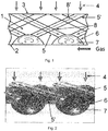
- a stator heat shield 1 for a gas turbine comprises a first surface 2 adapted to be exposed to hot gases flowing through the gas turbine during the operation of the gas turbine, that is, to face a hot gas flow path of the gas turbine. Further, the stator heat shield 1 comprises a second surface 3 opposite to the first surface 2. The second face faces away from the hot gas flow path and is connected to a cooling fluid supply. During the operation of the gas turbine, the second surface 3 is exposed to cooling fluid 4. To direct the cooling fluid 4 from the second surface 3 towards the first surface 2, the stator heat shield 1 has through cooling channels 5, 5'. Each of the cooling channels 5, 5' has a feeding inlet to receive the cooling fluid 4 and an outlet to discharge a cooling fluid jet.
- Cavities 6 are provided on the first surface 2, which have a special profile with an expansion towards the first surface 2 washed by hot gas.
- the cavities are open to the hot gas flow path.
- Each cavity 6 has two cooling channels 5, 5' open thereto.
- the two cooling channels 5, 5' are inclined towards each other and arranged so as to provide a circulation 7 of the cooling fluid in the cavity 6.
- the cooling channels 5, 5' may be inclined to the surface of the SHS at optimal 30°.
- the cavities 6 are profiled so as to allow a circulation 7 of the cooling fluid in the cavities 6. Due the circulation 7, the cooling fluid may be retained in the cavities 6 before it is sucked out of the retaining cavity 6 mixing with hot gas and reducing downstream exposure temperature at the SHS and the tip region of a passing blade. This arrangement allows external cooling of the SHS and, at the same time, mitigation of the impact of rubbing event, preventing thereby discharge holes from closure.
- cooling channels 5, 5' extending through the body of the stator heat shield 1 define an internal convective cooling system of the SHS. Therefore, the cooling channels 5, 5' may be provided as convective channels or tubes.
- the inclined cooling channels 5, 5' of one cavity 6 intersect with the inclined cooling channels 5, 5' of the other cavities 6 to arrange intersections 8, 8'.
- one 5 of the two cooling channels 5, 5' associated with one cavity 6 intersects with one 5' of the two cooling channels 5, 5' of a neighboring cavity 6 to arrange a first intersection 8.
- the first intersection 8 is located substantially between said one cavity 6 and said neighboring cavity 6, as a projection onto the first surface 2.
- Said one 5 of the two cooling channels 5, 5' associated with one cavity 6 may intersect also with one 5' of the two though channels 5, 5' of at least one cavity next to said neighboring cavity to arrange at least a second intersection 8'.
- Each intersection 8, 8' includes two intersecting cooling channels 5, 5'.
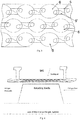
- Fig.2 it can be seen that the central axes of the two cooling channels 5, 5' open into the same cavity 6 are offset, preferably half-diameter offset, relative to each other to arrange swirling interaction between the discharged jets of the cooling fluid and thereby a more stable circulation 7.
- the cooling channel 5 of one cavity 6 and the cooling channel 5' of another cavity 6 intersect with each other so that their axes are offset, preferably half-diameter offset, relative to each other so as not to be arranged in one common plane.
- the intersecting cooling channels 5, 5' are in fluid communication in the intersections 8, 8'. In application to cooling effect of the cooling channels, the intersection and offset of the though channels 5, 5' allows achievement of high heat transfer enhancement rates with moderate pressure losses.
- the cavities 6 are arranged in rows extending in the longitudinal direction of the stator heat shield 1.
- the rows of the cavities 6 are staggered to arrange a homogeneous external cooling network.
- the offset of the central axes of the intersecting cooling channels 5, 5' can be also seen in Fig. 3 , too.
- Fig. 4 shows an example of implementation of the stator heat shield.
- the stator heat shield is facing the rotor.
- a plurality of the cavities are arranged on the side of the stator heat shield which is facing the hot gas flow side.
- Two cooling channels extend from the cooling air supply side to the hot gas flow path side of the stator heat shield and open into the cavities.
Landscapes
- Engineering & Computer Science (AREA)
- Mechanical Engineering (AREA)
- General Engineering & Computer Science (AREA)
- Turbine Rotor Nozzle Sealing (AREA)
Applications Claiming Priority (1)
| Application Number | Priority Date | Filing Date | Title |
|---|---|---|---|
| RU2016102173A RU2706210C2 (ru) | 2016-01-25 | 2016-01-25 | Тепловой экран статора для газовой турбины, газовая турбина с таким тепловым экраном статора и способ охлаждения теплового экрана статора |
Publications (2)
| Publication Number | Publication Date |
|---|---|
| EP3196423A1 true EP3196423A1 (de) | 2017-07-26 |
| EP3196423B1 EP3196423B1 (de) | 2018-12-05 |
Family
ID=57914779
Family Applications (1)
| Application Number | Title | Priority Date | Filing Date |
|---|---|---|---|
| EP17153154.4A Active EP3196423B1 (de) | 2016-01-25 | 2017-01-25 | Statorhitzeschild für eine gasturbine und zugehörige gasturbine |
Country Status (6)
| Country | Link |
|---|---|
| US (1) | US10450885B2 (de) |
| EP (1) | EP3196423B1 (de) |
| JP (1) | JP2017166475A (de) |
| KR (1) | KR20170088769A (de) |
| CN (1) | CN106996319B (de) |
| RU (1) | RU2706210C2 (de) |
Cited By (2)
| Publication number | Priority date | Publication date | Assignee | Title |
|---|---|---|---|---|
| US11359495B2 (en) | 2019-01-07 | 2022-06-14 | Rolls- Royce Corporation | Coverage cooling holes |
| US11566532B2 (en) | 2020-12-04 | 2023-01-31 | Ge Avio S.R.L. | Turbine clearance control system |
Families Citing this family (3)
| Publication number | Priority date | Publication date | Assignee | Title |
|---|---|---|---|---|
| CN111911962A (zh) * | 2020-08-18 | 2020-11-10 | 西北工业大学 | 一种新型火焰筒壁面冷却结构 |
| US11512611B2 (en) | 2021-02-09 | 2022-11-29 | General Electric Company | Stator apparatus for a gas turbine engine |
| CN114575932B (zh) * | 2022-04-02 | 2024-07-05 | 中国航发沈阳发动机研究所 | 一种涡轮叶片尾缘半劈缝冷却结构 |
Citations (15)
| Publication number | Priority date | Publication date | Assignee | Title |
|---|---|---|---|---|
| US5165847A (en) | 1991-05-20 | 1992-11-24 | General Electric Company | Tapered enlargement metering inlet channel for a shroud cooling assembly of gas turbine engines |
| US5169287A (en) | 1991-05-20 | 1992-12-08 | General Electric Company | Shroud cooling assembly for gas turbine engine |
| US5538393A (en) | 1995-01-31 | 1996-07-23 | United Technologies Corporation | Turbine shroud segment with serpentine cooling channels having a bend passage |
| DE19619438A1 (de) * | 1996-05-14 | 1997-11-20 | Asea Brown Boveri | Wärmestausegment für eine Turbomaschine |
| US6139257A (en) | 1998-03-23 | 2000-10-31 | General Electric Company | Shroud cooling assembly for gas turbine engine |
| US6155778A (en) * | 1998-12-30 | 2000-12-05 | General Electric Company | Recessed turbine shroud |
| US6354795B1 (en) | 2000-07-27 | 2002-03-12 | General Electric Company | Shroud cooling segment and assembly |
| US20050058534A1 (en) | 2003-09-17 | 2005-03-17 | Ching-Pang Lee | Network cooled coated wall |
| EP1533478A2 (de) | 2003-11-24 | 2005-05-25 | General Electric Company | Asymmetrische Kühlelemente eines Turbinendeckbandes |
| US20090035125A1 (en) | 2006-03-02 | 2009-02-05 | Shu Fujimoto | Impingement cooled structure |
| US7988410B1 (en) * | 2007-11-19 | 2011-08-02 | Florida Turbine Technologies, Inc. | Blade tip shroud with circular grooves |
| US20120027576A1 (en) | 2010-07-30 | 2012-02-02 | Rolls-Royce Plc | Turbine stage shroud segment |
| US20120251295A1 (en) | 2011-03-28 | 2012-10-04 | Rolls-Royce Plc | Gas turbine engine component |
| EP2549063A1 (de) | 2011-07-21 | 2013-01-23 | Siemens Aktiengesellschaft | Hitzeschildelement für eine Gasturbine |
| WO2013129530A1 (ja) | 2012-02-29 | 2013-09-06 | 株式会社Ihi | ガスタービンエンジン |
Family Cites Families (9)
| Publication number | Priority date | Publication date | Assignee | Title |
|---|---|---|---|---|
| SU580334A1 (ru) * | 1972-10-30 | 1977-11-15 | Ленинградский Дважды Ордена Ленина Металлический Завод Им. Ххп Съезда Кпсс | Защитный экран |
| US4013376A (en) * | 1975-06-02 | 1977-03-22 | United Technologies Corporation | Coolable blade tip shroud |
| GB8830152D0 (en) * | 1988-12-23 | 1989-09-20 | Rolls Royce Plc | Cooled turbomachinery components |
| US5161942A (en) * | 1990-10-24 | 1992-11-10 | Westinghouse Electric Corp. | Moisture drainage of honeycomb seals |
| US5660523A (en) * | 1992-02-03 | 1997-08-26 | General Electric Company | Turbine blade squealer tip peripheral end wall with cooling passage arrangement |
| RU2040696C1 (ru) * | 1992-03-11 | 1995-07-25 | Акционерное общество открытого типа "Ленинградский Металлический завод" | Ступень осевой турбины |
| RU2530685C2 (ru) * | 2010-03-25 | 2014-10-10 | Дженерал Электрик Компани | Структуры ударного воздействия для систем охлаждения |
| US8905713B2 (en) * | 2010-05-28 | 2014-12-09 | General Electric Company | Articles which include chevron film cooling holes, and related processes |
| US8475121B1 (en) * | 2011-01-17 | 2013-07-02 | Florida Turbine Technologies, Inc. | Ring segment for industrial gas turbine |
-
2016
- 2016-01-25 RU RU2016102173A patent/RU2706210C2/ru active
-
2017
- 2017-01-24 KR KR1020170011031A patent/KR20170088769A/ko not_active Withdrawn
- 2017-01-25 EP EP17153154.4A patent/EP3196423B1/de active Active
- 2017-01-25 JP JP2017011094A patent/JP2017166475A/ja active Pending
- 2017-01-25 CN CN201710056289.2A patent/CN106996319B/zh active Active
- 2017-01-25 US US15/415,420 patent/US10450885B2/en active Active
Patent Citations (15)
| Publication number | Priority date | Publication date | Assignee | Title |
|---|---|---|---|---|
| US5165847A (en) | 1991-05-20 | 1992-11-24 | General Electric Company | Tapered enlargement metering inlet channel for a shroud cooling assembly of gas turbine engines |
| US5169287A (en) | 1991-05-20 | 1992-12-08 | General Electric Company | Shroud cooling assembly for gas turbine engine |
| US5538393A (en) | 1995-01-31 | 1996-07-23 | United Technologies Corporation | Turbine shroud segment with serpentine cooling channels having a bend passage |
| DE19619438A1 (de) * | 1996-05-14 | 1997-11-20 | Asea Brown Boveri | Wärmestausegment für eine Turbomaschine |
| US6139257A (en) | 1998-03-23 | 2000-10-31 | General Electric Company | Shroud cooling assembly for gas turbine engine |
| US6155778A (en) * | 1998-12-30 | 2000-12-05 | General Electric Company | Recessed turbine shroud |
| US6354795B1 (en) | 2000-07-27 | 2002-03-12 | General Electric Company | Shroud cooling segment and assembly |
| US20050058534A1 (en) | 2003-09-17 | 2005-03-17 | Ching-Pang Lee | Network cooled coated wall |
| EP1533478A2 (de) | 2003-11-24 | 2005-05-25 | General Electric Company | Asymmetrische Kühlelemente eines Turbinendeckbandes |
| US20090035125A1 (en) | 2006-03-02 | 2009-02-05 | Shu Fujimoto | Impingement cooled structure |
| US7988410B1 (en) * | 2007-11-19 | 2011-08-02 | Florida Turbine Technologies, Inc. | Blade tip shroud with circular grooves |
| US20120027576A1 (en) | 2010-07-30 | 2012-02-02 | Rolls-Royce Plc | Turbine stage shroud segment |
| US20120251295A1 (en) | 2011-03-28 | 2012-10-04 | Rolls-Royce Plc | Gas turbine engine component |
| EP2549063A1 (de) | 2011-07-21 | 2013-01-23 | Siemens Aktiengesellschaft | Hitzeschildelement für eine Gasturbine |
| WO2013129530A1 (ja) | 2012-02-29 | 2013-09-06 | 株式会社Ihi | ガスタービンエンジン |
Cited By (2)
| Publication number | Priority date | Publication date | Assignee | Title |
|---|---|---|---|---|
| US11359495B2 (en) | 2019-01-07 | 2022-06-14 | Rolls- Royce Corporation | Coverage cooling holes |
| US11566532B2 (en) | 2020-12-04 | 2023-01-31 | Ge Avio S.R.L. | Turbine clearance control system |
Also Published As
| Publication number | Publication date |
|---|---|
| CN106996319B (zh) | 2021-11-09 |
| EP3196423B1 (de) | 2018-12-05 |
| US10450885B2 (en) | 2019-10-22 |
| CN106996319A (zh) | 2017-08-01 |
| RU2016102173A (ru) | 2017-07-26 |
| US20170211405A1 (en) | 2017-07-27 |
| KR20170088769A (ko) | 2017-08-02 |
| JP2017166475A (ja) | 2017-09-21 |
| RU2016102173A3 (de) | 2019-06-11 |
| RU2706210C2 (ru) | 2019-11-14 |
Similar Documents
| Publication | Publication Date | Title |
|---|---|---|
| EP3196423B1 (de) | Statorhitzeschild für eine gasturbine und zugehörige gasturbine | |
| US8057181B1 (en) | Multiple expansion film cooling hole for turbine airfoil | |
| US9822654B2 (en) | Arrangement for cooling a component in the hot gas path of a gas turbine | |
| CN103161513B (zh) | 改进的用于燃气涡轮发动机的喷嘴叶片 | |
| US7988410B1 (en) | Blade tip shroud with circular grooves | |
| EP3124745B1 (de) | Turbomaschinenkomponente mit filmgekühlter wand | |
| US8439634B1 (en) | BOAS with cooled sinusoidal shaped grooves | |
| US8858175B2 (en) | Film hole trench | |
| EP3124746B1 (de) | Verfahren zur kühlung einer turbomaschinenkomponente und turbomaschinenkomponente | |
| US8708645B1 (en) | Turbine rotor blade with multi-vortex tip cooling channels | |
| US8043059B1 (en) | Turbine blade with multi-vortex tip cooling and sealing | |
| US20140286751A1 (en) | Cooled turbine ring segments with intermediate pressure plenums | |
| US8961136B1 (en) | Turbine airfoil with film cooling hole | |
| US8613597B1 (en) | Turbine blade with trailing edge cooling | |
| CN101535602A (zh) | 涡轮叶片 | |
| CN102200056A (zh) | 用于冷却系统的冲击结构 | |
| WO2014189904A1 (en) | Gas turbine engine blade | |
| JP2015132266A (ja) | 冷却式ステータヒートシールド | |
| JP6598999B2 (ja) | 軸方向隔壁を特徴とする後縁冷却を備えるタービン翼 | |
| CN113250758B (zh) | 涡轮喷嘴部段和包括这种涡轮喷嘴部段的涡轮喷嘴 | |
| US10900361B2 (en) | Turbine airfoil with biased trailing edge cooling arrangement | |
| JP2009287511A (ja) | タービン用翼 | |
| JP2017044092A (ja) | タービン動翼、及び、ガスタービン | |
| JP6583780B2 (ja) | 翼及びこれを備えるガスタービン | |
| JP2001207863A (ja) | ガスタービン |
Legal Events
| Date | Code | Title | Description |
|---|---|---|---|
| PUAI | Public reference made under article 153(3) epc to a published international application that has entered the european phase |
Free format text: ORIGINAL CODE: 0009012 |
|
| STAA | Information on the status of an ep patent application or granted ep patent |
Free format text: STATUS: THE APPLICATION HAS BEEN PUBLISHED |
|
| AK | Designated contracting states |
Kind code of ref document: A1 Designated state(s): AL AT BE BG CH CY CZ DE DK EE ES FI FR GB GR HR HU IE IS IT LI LT LU LV MC MK MT NL NO PL PT RO RS SE SI SK SM TR |
|
| AX | Request for extension of the european patent |
Extension state: BA ME |
|
| STAA | Information on the status of an ep patent application or granted ep patent |
Free format text: STATUS: REQUEST FOR EXAMINATION WAS MADE |
|
| 17P | Request for examination filed |
Effective date: 20180125 |
|
| RBV | Designated contracting states (corrected) |
Designated state(s): AL AT BE BG CH CY CZ DE DK EE ES FI FR GB GR HR HU IE IS IT LI LT LU LV MC MK MT NL NO PL PT RO RS SE SI SK SM TR |
|
| REG | Reference to a national code |
Ref country code: DE Ref legal event code: R079 Ref document number: 602017001106 Country of ref document: DE Free format text: PREVIOUS MAIN CLASS: F01D0025120000 Ipc: F01D0011240000 |
|
| RIC1 | Information provided on ipc code assigned before grant |
Ipc: F01D 11/24 20060101AFI20180504BHEP |
|
| GRAP | Despatch of communication of intention to grant a patent |
Free format text: ORIGINAL CODE: EPIDOSNIGR1 |
|
| STAA | Information on the status of an ep patent application or granted ep patent |
Free format text: STATUS: GRANT OF PATENT IS INTENDED |
|
| INTG | Intention to grant announced |
Effective date: 20180615 |
|
| GRAS | Grant fee paid |
Free format text: ORIGINAL CODE: EPIDOSNIGR3 |
|
| GRAA | (expected) grant |
Free format text: ORIGINAL CODE: 0009210 |
|
| STAA | Information on the status of an ep patent application or granted ep patent |
Free format text: STATUS: THE PATENT HAS BEEN GRANTED |
|
| AK | Designated contracting states |
Kind code of ref document: B1 Designated state(s): AL AT BE BG CH CY CZ DE DK EE ES FI FR GB GR HR HU IE IS IT LI LT LU LV MC MK MT NL NO PL PT RO RS SE SI SK SM TR |
|
| REG | Reference to a national code |
Ref country code: GB Ref legal event code: FG4D |
|
| REG | Reference to a national code |
Ref country code: CH Ref legal event code: EP |
|
| REG | Reference to a national code |
Ref country code: AT Ref legal event code: REF Ref document number: 1073340 Country of ref document: AT Kind code of ref document: T Effective date: 20181215 |
|
| REG | Reference to a national code |
Ref country code: IE Ref legal event code: FG4D |
|
| REG | Reference to a national code |
Ref country code: DE Ref legal event code: R096 Ref document number: 602017001106 Country of ref document: DE |
|
| REG | Reference to a national code |
Ref country code: NL Ref legal event code: MP Effective date: 20181205 |
|
| REG | Reference to a national code |
Ref country code: AT Ref legal event code: MK05 Ref document number: 1073340 Country of ref document: AT Kind code of ref document: T Effective date: 20181205 |
|
| REG | Reference to a national code |
Ref country code: LT Ref legal event code: MG4D |
|
| PG25 | Lapsed in a contracting state [announced via postgrant information from national office to epo] |
Ref country code: NO Free format text: LAPSE BECAUSE OF FAILURE TO SUBMIT A TRANSLATION OF THE DESCRIPTION OR TO PAY THE FEE WITHIN THE PRESCRIBED TIME-LIMIT Effective date: 20190305 Ref country code: AT Free format text: LAPSE BECAUSE OF FAILURE TO SUBMIT A TRANSLATION OF THE DESCRIPTION OR TO PAY THE FEE WITHIN THE PRESCRIBED TIME-LIMIT Effective date: 20181205 Ref country code: LT Free format text: LAPSE BECAUSE OF FAILURE TO SUBMIT A TRANSLATION OF THE DESCRIPTION OR TO PAY THE FEE WITHIN THE PRESCRIBED TIME-LIMIT Effective date: 20181205 Ref country code: FI Free format text: LAPSE BECAUSE OF FAILURE TO SUBMIT A TRANSLATION OF THE DESCRIPTION OR TO PAY THE FEE WITHIN THE PRESCRIBED TIME-LIMIT Effective date: 20181205 Ref country code: BG Free format text: LAPSE BECAUSE OF FAILURE TO SUBMIT A TRANSLATION OF THE DESCRIPTION OR TO PAY THE FEE WITHIN THE PRESCRIBED TIME-LIMIT Effective date: 20190305 Ref country code: LV Free format text: LAPSE BECAUSE OF FAILURE TO SUBMIT A TRANSLATION OF THE DESCRIPTION OR TO PAY THE FEE WITHIN THE PRESCRIBED TIME-LIMIT Effective date: 20181205 Ref country code: HR Free format text: LAPSE BECAUSE OF FAILURE TO SUBMIT A TRANSLATION OF THE DESCRIPTION OR TO PAY THE FEE WITHIN THE PRESCRIBED TIME-LIMIT Effective date: 20181205 Ref country code: ES Free format text: LAPSE BECAUSE OF FAILURE TO SUBMIT A TRANSLATION OF THE DESCRIPTION OR TO PAY THE FEE WITHIN THE PRESCRIBED TIME-LIMIT Effective date: 20181205 |
|
| PG25 | Lapsed in a contracting state [announced via postgrant information from national office to epo] |
Ref country code: AL Free format text: LAPSE BECAUSE OF FAILURE TO SUBMIT A TRANSLATION OF THE DESCRIPTION OR TO PAY THE FEE WITHIN THE PRESCRIBED TIME-LIMIT Effective date: 20181205 Ref country code: GR Free format text: LAPSE BECAUSE OF FAILURE TO SUBMIT A TRANSLATION OF THE DESCRIPTION OR TO PAY THE FEE WITHIN THE PRESCRIBED TIME-LIMIT Effective date: 20190306 Ref country code: RS Free format text: LAPSE BECAUSE OF FAILURE TO SUBMIT A TRANSLATION OF THE DESCRIPTION OR TO PAY THE FEE WITHIN THE PRESCRIBED TIME-LIMIT Effective date: 20181205 Ref country code: SE Free format text: LAPSE BECAUSE OF FAILURE TO SUBMIT A TRANSLATION OF THE DESCRIPTION OR TO PAY THE FEE WITHIN THE PRESCRIBED TIME-LIMIT Effective date: 20181205 |
|
| PG25 | Lapsed in a contracting state [announced via postgrant information from national office to epo] |
Ref country code: NL Free format text: LAPSE BECAUSE OF FAILURE TO SUBMIT A TRANSLATION OF THE DESCRIPTION OR TO PAY THE FEE WITHIN THE PRESCRIBED TIME-LIMIT Effective date: 20181205 |
|
| PG25 | Lapsed in a contracting state [announced via postgrant information from national office to epo] |
Ref country code: PL Free format text: LAPSE BECAUSE OF FAILURE TO SUBMIT A TRANSLATION OF THE DESCRIPTION OR TO PAY THE FEE WITHIN THE PRESCRIBED TIME-LIMIT Effective date: 20181205 Ref country code: PT Free format text: LAPSE BECAUSE OF FAILURE TO SUBMIT A TRANSLATION OF THE DESCRIPTION OR TO PAY THE FEE WITHIN THE PRESCRIBED TIME-LIMIT Effective date: 20190405 Ref country code: CZ Free format text: LAPSE BECAUSE OF FAILURE TO SUBMIT A TRANSLATION OF THE DESCRIPTION OR TO PAY THE FEE WITHIN THE PRESCRIBED TIME-LIMIT Effective date: 20181205 Ref country code: IT Free format text: LAPSE BECAUSE OF FAILURE TO SUBMIT A TRANSLATION OF THE DESCRIPTION OR TO PAY THE FEE WITHIN THE PRESCRIBED TIME-LIMIT Effective date: 20181205 |
|
| PG25 | Lapsed in a contracting state [announced via postgrant information from national office to epo] |
Ref country code: IS Free format text: LAPSE BECAUSE OF FAILURE TO SUBMIT A TRANSLATION OF THE DESCRIPTION OR TO PAY THE FEE WITHIN THE PRESCRIBED TIME-LIMIT Effective date: 20190405 Ref country code: RO Free format text: LAPSE BECAUSE OF FAILURE TO SUBMIT A TRANSLATION OF THE DESCRIPTION OR TO PAY THE FEE WITHIN THE PRESCRIBED TIME-LIMIT Effective date: 20181205 Ref country code: EE Free format text: LAPSE BECAUSE OF FAILURE TO SUBMIT A TRANSLATION OF THE DESCRIPTION OR TO PAY THE FEE WITHIN THE PRESCRIBED TIME-LIMIT Effective date: 20181205 Ref country code: SK Free format text: LAPSE BECAUSE OF FAILURE TO SUBMIT A TRANSLATION OF THE DESCRIPTION OR TO PAY THE FEE WITHIN THE PRESCRIBED TIME-LIMIT Effective date: 20181205 Ref country code: SM Free format text: LAPSE BECAUSE OF FAILURE TO SUBMIT A TRANSLATION OF THE DESCRIPTION OR TO PAY THE FEE WITHIN THE PRESCRIBED TIME-LIMIT Effective date: 20181205 |
|
| REG | Reference to a national code |
Ref country code: DE Ref legal event code: R097 Ref document number: 602017001106 Country of ref document: DE |
|
| PG25 | Lapsed in a contracting state [announced via postgrant information from national office to epo] |
Ref country code: LU Free format text: LAPSE BECAUSE OF NON-PAYMENT OF DUE FEES Effective date: 20190125 |
|
| PLBE | No opposition filed within time limit |
Free format text: ORIGINAL CODE: 0009261 |
|
| STAA | Information on the status of an ep patent application or granted ep patent |
Free format text: STATUS: NO OPPOSITION FILED WITHIN TIME LIMIT |
|
| REG | Reference to a national code |
Ref country code: BE Ref legal event code: MM Effective date: 20190131 |
|
| REG | Reference to a national code |
Ref country code: IE Ref legal event code: MM4A |
|
| PG25 | Lapsed in a contracting state [announced via postgrant information from national office to epo] |
Ref country code: DK Free format text: LAPSE BECAUSE OF FAILURE TO SUBMIT A TRANSLATION OF THE DESCRIPTION OR TO PAY THE FEE WITHIN THE PRESCRIBED TIME-LIMIT Effective date: 20181205 Ref country code: MC Free format text: LAPSE BECAUSE OF FAILURE TO SUBMIT A TRANSLATION OF THE DESCRIPTION OR TO PAY THE FEE WITHIN THE PRESCRIBED TIME-LIMIT Effective date: 20181205 Ref country code: FR Free format text: LAPSE BECAUSE OF NON-PAYMENT OF DUE FEES Effective date: 20190205 Ref country code: SI Free format text: LAPSE BECAUSE OF FAILURE TO SUBMIT A TRANSLATION OF THE DESCRIPTION OR TO PAY THE FEE WITHIN THE PRESCRIBED TIME-LIMIT Effective date: 20181205 |
|
| 26N | No opposition filed |
Effective date: 20190906 |
|
| PG25 | Lapsed in a contracting state [announced via postgrant information from national office to epo] |
Ref country code: BE Free format text: LAPSE BECAUSE OF NON-PAYMENT OF DUE FEES Effective date: 20190131 |
|
| PG25 | Lapsed in a contracting state [announced via postgrant information from national office to epo] |
Ref country code: IE Free format text: LAPSE BECAUSE OF NON-PAYMENT OF DUE FEES Effective date: 20190125 |
|
| PG25 | Lapsed in a contracting state [announced via postgrant information from national office to epo] |
Ref country code: TR Free format text: LAPSE BECAUSE OF FAILURE TO SUBMIT A TRANSLATION OF THE DESCRIPTION OR TO PAY THE FEE WITHIN THE PRESCRIBED TIME-LIMIT Effective date: 20181205 |
|
| PG25 | Lapsed in a contracting state [announced via postgrant information from national office to epo] |
Ref country code: MT Free format text: LAPSE BECAUSE OF NON-PAYMENT OF DUE FEES Effective date: 20190125 |
|
| REG | Reference to a national code |
Ref country code: CH Ref legal event code: PL |
|
| PG25 | Lapsed in a contracting state [announced via postgrant information from national office to epo] |
Ref country code: LI Free format text: LAPSE BECAUSE OF NON-PAYMENT OF DUE FEES Effective date: 20200131 Ref country code: CH Free format text: LAPSE BECAUSE OF NON-PAYMENT OF DUE FEES Effective date: 20200131 |
|
| PG25 | Lapsed in a contracting state [announced via postgrant information from national office to epo] |
Ref country code: CY Free format text: LAPSE BECAUSE OF FAILURE TO SUBMIT A TRANSLATION OF THE DESCRIPTION OR TO PAY THE FEE WITHIN THE PRESCRIBED TIME-LIMIT Effective date: 20181205 |
|
| PG25 | Lapsed in a contracting state [announced via postgrant information from national office to epo] |
Ref country code: HU Free format text: LAPSE BECAUSE OF FAILURE TO SUBMIT A TRANSLATION OF THE DESCRIPTION OR TO PAY THE FEE WITHIN THE PRESCRIBED TIME-LIMIT; INVALID AB INITIO Effective date: 20170125 |
|
| GBPC | Gb: european patent ceased through non-payment of renewal fee |
Effective date: 20210125 |
|
| PG25 | Lapsed in a contracting state [announced via postgrant information from national office to epo] |
Ref country code: GB Free format text: LAPSE BECAUSE OF NON-PAYMENT OF DUE FEES Effective date: 20210125 |
|
| PG25 | Lapsed in a contracting state [announced via postgrant information from national office to epo] |
Ref country code: MK Free format text: LAPSE BECAUSE OF FAILURE TO SUBMIT A TRANSLATION OF THE DESCRIPTION OR TO PAY THE FEE WITHIN THE PRESCRIBED TIME-LIMIT Effective date: 20181205 |
|
| P01 | Opt-out of the competence of the unified patent court (upc) registered |
Effective date: 20240430 |
|
| PGFP | Annual fee paid to national office [announced via postgrant information from national office to epo] |
Ref country code: DE Payment date: 20260120 Year of fee payment: 10 |