EP3198230B1 - System und verfahren zur aktiven auswuchtung/unterdrückung von magnetischen interferenzen bei einem magnetsensor - Google Patents
System und verfahren zur aktiven auswuchtung/unterdrückung von magnetischen interferenzen bei einem magnetsensor Download PDFInfo
- Publication number
- EP3198230B1 EP3198230B1 EP15844184.0A EP15844184A EP3198230B1 EP 3198230 B1 EP3198230 B1 EP 3198230B1 EP 15844184 A EP15844184 A EP 15844184A EP 3198230 B1 EP3198230 B1 EP 3198230B1
- Authority
- EP
- European Patent Office
- Prior art keywords
- stator
- magnet
- magnetic field
- magnetic
- collector
- Prior art date
- Legal status (The legal status is an assumption and is not a legal conclusion. Google has not performed a legal analysis and makes no representation as to the accuracy of the status listed.)
- Active
Links
Images




Classifications
-
- G—PHYSICS
- G01—MEASURING; TESTING
- G01D—MEASURING NOT SPECIALLY ADAPTED FOR A SPECIFIC VARIABLE; ARRANGEMENTS FOR MEASURING TWO OR MORE VARIABLES NOT COVERED IN A SINGLE OTHER SUBCLASS; TARIFF METERING APPARATUS; MEASURING OR TESTING NOT OTHERWISE PROVIDED FOR
- G01D5/00—Mechanical means for transferring the output of a sensing member; Means for converting the output of a sensing member to another variable where the form or nature of the sensing member does not constrain the means for converting; Transducers not specially adapted for a specific variable
- G01D5/12—Mechanical means for transferring the output of a sensing member; Means for converting the output of a sensing member to another variable where the form or nature of the sensing member does not constrain the means for converting; Transducers not specially adapted for a specific variable using electric or magnetic means
-
- G—PHYSICS
- G01—MEASURING; TESTING
- G01D—MEASURING NOT SPECIALLY ADAPTED FOR A SPECIFIC VARIABLE; ARRANGEMENTS FOR MEASURING TWO OR MORE VARIABLES NOT COVERED IN A SINGLE OTHER SUBCLASS; TARIFF METERING APPARATUS; MEASURING OR TESTING NOT OTHERWISE PROVIDED FOR
- G01D5/00—Mechanical means for transferring the output of a sensing member; Means for converting the output of a sensing member to another variable where the form or nature of the sensing member does not constrain the means for converting; Transducers not specially adapted for a specific variable
- G01D5/12—Mechanical means for transferring the output of a sensing member; Means for converting the output of a sensing member to another variable where the form or nature of the sensing member does not constrain the means for converting; Transducers not specially adapted for a specific variable using electric or magnetic means
- G01D5/244—Mechanical means for transferring the output of a sensing member; Means for converting the output of a sensing member to another variable where the form or nature of the sensing member does not constrain the means for converting; Transducers not specially adapted for a specific variable using electric or magnetic means influencing characteristics of pulses or pulse trains; generating pulses or pulse trains
- G01D5/24428—Error prevention
-
- G—PHYSICS
- G01—MEASURING; TESTING
- G01L—MEASURING FORCE, STRESS, TORQUE, WORK, MECHANICAL POWER, MECHANICAL EFFICIENCY, OR FLUID PRESSURE
- G01L3/00—Measuring torque, work, mechanical power, or mechanical efficiency, in general
- G01L3/02—Rotary-transmission dynamometers
- G01L3/04—Rotary-transmission dynamometers wherein the torque-transmitting element comprises a torsionally-flexible shaft
- G01L3/10—Rotary-transmission dynamometers wherein the torque-transmitting element comprises a torsionally-flexible shaft involving electric or magnetic means for indicating
- G01L3/101—Rotary-transmission dynamometers wherein the torque-transmitting element comprises a torsionally-flexible shaft involving electric or magnetic means for indicating involving magnetic or electromagnetic means
-
- G—PHYSICS
- G01—MEASURING; TESTING
- G01R—MEASURING ELECTRIC VARIABLES; MEASURING MAGNETIC VARIABLES
- G01R33/00—Arrangements or instruments for measuring magnetic variables
- G01R33/0017—Means for compensating offset magnetic fields or the magnetic flux to be measured; Means for generating calibration magnetic fields
-
- G—PHYSICS
- G01—MEASURING; TESTING
- G01R—MEASURING ELECTRIC VARIABLES; MEASURING MAGNETIC VARIABLES
- G01R33/00—Arrangements or instruments for measuring magnetic variables
- G01R33/007—Environmental aspects, e.g. temperature variations, radiation, stray fields
- G01R33/0076—Protection, e.g. with housings against stray fields
-
- G—PHYSICS
- G01—MEASURING; TESTING
- G01R—MEASURING ELECTRIC VARIABLES; MEASURING MAGNETIC VARIABLES
- G01R33/00—Arrangements or instruments for measuring magnetic variables
- G01R33/02—Measuring direction or magnitude of magnetic fields or magnetic flux
- G01R33/025—Compensating stray fields
Definitions
- Embodiments of the invention relate to balancing and/or cancelling of magnetic interference in a magnetic sensor, specifically a torque and/or angle sensor or a torque and/or index sensor.
- Torque and angle sensors typically include a magnetic sensing element.
- the magnetic sensing elements usually include a magnet or other magnetic component. Often the magnet from one of the sensors interferes with the sensing elements from the other sensor. This interference is referred to as "cross-talk.” Among other things, cross-talk can lead to incorrect sensor readings.
- each a sensing system comprising a first magnet having a first magnetic field; a first stator configured to receive the first magnetic field; a second stator configured to receive the first magnetic field; a first collector configured to collect the first magnetic field from the first stator; a second collector configured to collect the first magnetic field from the second stator; a magnetic sensing element configured to sense the first magnetic field; a second magnet having a second magnetic field; and a third magnet having a third magnetical field.
- Embodiments of the invention help solve or reduce the impact of these problems by a sensing system as defined by independent claim 1, a sensing system as defined by independent claim 7 or a method of sensing as defined by independent claim 9.
- Fig. 1 illustrates a first sensor 100 according to one embodiment.
- the first sensor 100 is used in connection with a vehicle steering system that includes an input shaft 105 and an output shaft 110.
- the input shaft 105 and the output shaft 110 are connected via a torsion bar (not shown).
- the torsion bar has a torsional rigidity or torsion spring constant of a predetermined or known amount. Rotational motion of the input shaft 105 relative to the output shaft 110 produces a relative angular displacement between the input shaft 105 and the output shaft 110 proportional to the torque exerted.
- the first sensor 100 detects, or senses, a torque and/or a steering angle between the input shaft 105 and the output shaft 110.
- the sensor 100 includes a first magnet 115 coupled to the input shaft 105, and first and second stators 120 and 125 coupled to the output shaft 110.
- the first magnet 115 is coupled to the output shaft 110, while the first stator 120 and the second stator 125 are coupled to the input shaft 105.
- the sensor 100 also includes a first collector 130 and a second collector 135.
- the first collector 130 and second collector 135 are located proximate to (for example, in one embodiment, within a distance of about 0.2mm to about 2.0mm) the first stator 120 and the second stator 125, respectively.
- the first and second collectors 130 and 135 span across at least a portion of the first stator 120 and the second stator 125, respectively.
- the first collector 130 and the second collector 135 are magnetically coupled to at least one magnetic sensing element 140.
- the term "magnetically coupled" may, in general, be defined as magnetic communication between a first component and a second component, such that the first component is able to receive a magnetic flux from the second component, or vice versa. Such communication is dependent on the strength of the magnets used and the distances between components.
- the first component in order to be magnetically coupled, is a distance of approximately 0.2mm to 2.0mm from the second component.
- the magnetic sensing element 140 detects a first magnetic flux 300 ( Fig. 3 ) of the first magnet 115 between, or near to, the first collector 130 and the second collector 135.
- the magnetic sensing element 140 is a Hall-effect sensor.
- Fig. 1 also illustrates a second magnetic sensor 200.
- the second sensor 200 is located proximate the first sensor 100 and includes a second magnet 205.
- the second sensor 200 also includes third and fourth stators, third and fourth collectors, and a second magnetic sensing element.
- the third and fourth stators, third and fourth collectors, and the second magnetic sensing element are substantially similar to the first and second stators 120, 125, the first and second collectors 130, 135, and the magnetic sensing element 140.
- the first sensor 100 and the second sensor 200 are both part of a larger sensor or a sensor assembly, such as a rotation angle and torque sensor.
- the first sensor 100 may be a torque sensor while the second sensor 200 may be a rotational sensor, or vice-versa.
- the first sensor 100 includes a third magnet, or mirror magnet, 210.
- the mirror magnet 210 is positioned symmetrical to the second magnet 205, such that a mirror magnetic flux 275 ( Fig. 3 ) of the mirror magnet 210 is symmetrical to a second magnetic flux 250 ( Fig. 3 ) of the second magnet 205 of the second sensor 200.
- the mirror magnet 210 is further used within a third sensor, which may or may not be part of the overall sensor. In other embodiments, the mirror magnet 210 is used solely to cancel out the second magnetic flux 250 of the second magnet 205.
- the first stator 120 includes a first side 121, a second side 122, and a first periphery 124.
- the second stator 125 includes a first side 126, a second side 127, and a second periphery 129.
- the first magnet 115 is positioned adjacent the first side 121 of the first stator 120 and the first side 126 of the second stator 125. Additionally, as illustrated, the first magnet 115 is positioned between the first stator 120 and the second stator 125, in an axial direction running parallel to the x-axis in the reference coordinate system shown.
- the first magnet 115 is positioned between a first surface of the second side 122 of the first stator 120 and a second surface of the second side 127 of the second stator 125, in the axial direction.
- the second magnet 205 is positioned adjacent the second side 127 of the second stator 125 and the mirror magnet 210 is positioned adjacent the second side 122 of the first stator 120.
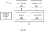
- the magnetic sensing element 140 is electrically coupled to a control system 212 ( Fig. 2 ).
- the control system 212 includes a controller 215 having a memory 220 and a processor 225.
- the controller 215 receives a signal from the magnetic sensing element 140 concerning a first magnetic flux 300 of the first magnet 115.
- the signal may include information or data regarding the magnitude and/or the polarity of the magnetic flux.
- the signal may be an analog or digital signal.
- the signal provides information related to a change in the magnetic flux.
- the controller 215 may be electrically connected to an input/output (I/O) interface 230 and a power supply 235.
- the controller 215 may further be electrically connected to the second sensor 200.
- the controller 215 is implemented partially or entirely on a semiconductor chip.
- the memory 220 includes, for example, a program storage area and a data storage area.
- the program storage area and the data storage area can include combinations of different types of memory, such as read-only memory (“ROM”), random access memory (“RAM”) (e.g., dynamic RAM ["DRAM”], synchronous DRAM ["SDRAM”], etc.), electrically erasable programmable read-only memory (“EEPROM”), flash memory, a hard disk, an SD card, or other suitable magnetic, optical, physical, or electronic memory devices.
- the processor 225 is connected to the memory 220 and executes software instructions. Software included in the implementation of the sensor 100 and/or controller 215 can be stored in the memory 220 of the controller 215.
- the software includes, for example, firmware, one or more applications, program data, filters, rules, one or more program modules, and other executable instructions.
- the controller 215 is configured to retrieve from memory 220 and execute, among other things, instructions related to the control processes and methods described herein. In other constructions, the controller 215 includes additional, fewer, or different components.
- the I/O interface 230 is configured to connect the controller 215 to a peripheral device, such as, for example, another controller or computer.
- the I/O interface 230 may be a wired connection, a wireless connection, or a combination of wired and wireless connections.
- the I/O interface 230 is configured to communicate measurement data associated with the sensor 100.
- the I/O interface 230 is used to electrically connect the controller 215 to a user-interface.
- the power supply 235 supplies a nominal voltage to the controller 215, as well as other components of the sensor 100.
- the power supply 235 is powered by a first voltage (e.g., from a battery) and provides the nominal voltage to the controller 215 and other components of the sensor 100.
- Fig. 3 illustrates a second magnetic flux 250 of the second magnet 205 and a third, or mirror, magnetic flux 275 of the mirror magnet 210.
- a magnet generates a magnetic field, which may be illustrated by magnetic flux, or magnetic flux lines.
- the mirror magnetic flux 275 is symmetrical to the second magnetic flux 250. Therefore, the second magnetic flux 250 and the mirror magnetic flux 275 cancel each other out.
- the only flux that affects the sensing element is the first magnetic flux 300.
- the magnetic sensing element 140 detects only the first magnetic flux 300.
- the symmetry is less than ideal a small or nominal amount of interference from the second and/or third magnets will occur.
- the torsion bar (not shown) regulates the relative angular displacement between the input shaft 105 and the output shaft 110.
- the relative angular displacement of the input shaft 105 and the output shaft 110 is equivalent to the angular displacement between the magnet 115 (which is coupled to the input shaft 105) and the first and second stators 120 and 125 (which are coupled to the output shaft 110).
- a zero position of the system is the position where there is zero or no torque exerted on the system and zero angular displacement between the magnet 115 and first and second stators 120 and 125. At the zero position, the magnet 115 and first and second stators 120 and 125 produce a net zero magnetic flux of the magnetic field or a net zero axial magnetic flux of the magnetic field.
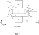
- Fig. 4 illustrates a second embodiment of a first sensor 100' located proximate a second sensor 200' having a second magnet 205'.
- a mirror magnet 210' is positioned such that the mirror magnetic flux 275' ( Fig. 5 ) of the mirror magnet 210' is symmetrical to the second magnetic flux 250' ( Fig. 5 ) of the second magnet 205'
- the first magnet 115 is positioned adjacent the first side 121 of the first stator 120 and adjacent the first side 126 of the second stator 125. As illustrated, the first magnet 115 is aligned axially with the x axis of the coordinate system shown and is positioned between the first stator 120 and the second stator 125.
- the second magnet 205' is positioned adjacent the second periphery 129 of the second stator 125 and the mirror magnet 210 is positioned adjacent the first periphery 124of the first stator 120. Additionally, the second magnet 205' and the mirror magnet 210' are aligned radially with respect to the longitudinal axis of the sensor 100'.
- Fig. 5 illustrates a second magnetic flux 250' of the second magnet 205' and a third, or mirror, magnetic flux 275' of the mirror magnet 210'.
- the mirror magnetic flux 275' is symmetrical to the second magnetic flux 250'. Therefore, the second magnetic flux 250' and the mirror magnetic flux 275' cancel each other out.
- the magnetic sensing element 140 detects only the first magnetic flux 300.
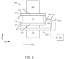
- Fig. 6 illustrates a third embodiment of a first sensor 100" located proximate a second sensor 200" having a second magnet 205".
- the second magnet 205" is magnetized in such a way that the resulting field is symmetric about the longitudinal axis of the sensor 100".
- the second magnet 205" is positioned substantially equal distances from the first stator and second stator 120, 125 of the first sensor 100".
- Such a positioning of the second magnet 205" results in a second magnetic flux 250" ( Fig. 7 ) which is symmetrical to the first and second stators 120, 125 and the first and second collectors 130, 135, such that the first and second stators 120, 125 and the first and second collectors 130, 135 receive approximately the same magnetic flux. Therefore, the magnetic sensing element 140 detects only the first magnetic flux 300.
- the second magnet 205" is radially separated from the first and second stators 120, 125.
- the invention provides, among other things, a system and method for balancing and/or cancelling magnetic interference in a magnetic sensor, specifically a torque and/or angle sensor.
Landscapes
- Physics & Mathematics (AREA)
- General Physics & Mathematics (AREA)
- Condensed Matter Physics & Semiconductors (AREA)
- Electromagnetism (AREA)
- Health & Medical Sciences (AREA)
- Engineering & Computer Science (AREA)
- Environmental & Geological Engineering (AREA)
- Toxicology (AREA)
- Transmission And Conversion Of Sensor Element Output (AREA)
- Measurement Of Length, Angles, Or The Like Using Electric Or Magnetic Means (AREA)
Claims (11)
- Ein Erfassungssystem, das Folgendes umfasst:einen ersten Magneten (115) mit einem ersten Magnetfeld (300), wobei der erste Magnet mit einer ersten Achse ausgerichtet ist;einen ersten Stator (120), der so konfiguriert ist, dass er das erste Magnetfeld (300) empfängt, wobei der erste Stator (120) mit der ersten Achse ausgerichtet ist;einen zweiten Stator (125), der so konfiguriert ist, dass er das erste Magnetfeld (300) empfängt, wobei der zweite Stator (125) mit der ersten Achse ausgerichtet ist,wobei der erste Magnet (115) zwischen dem ersten Stator (120) und dem zweiten Stator (125) angeordnet ist, und wobei der erste Magnet (115) in Bezug auf den ersten Stator (120) und den zweiten Stator (125) drehbar ist;einen ersten Kollektor (130), der so konfiguriert ist, dass er das erste Magnetfeld (300) von dem ersten Stator (120) empfängt;einen zweiten Kollektor (135), der so konfiguriert ist, dass er das erste Magnetfeld (300) vom zweiten Stator (125) empfängt;ein magnetisches Sensorelement (140), das konfiguriert ist, um das erste Magnetfeld (300) zu erfassen, wobei das magnetischeSensorelement (140) magnetisch mit dem ersten Kollektor (130) und dem zweiten Kollektor (135) gekoppelt ist;einen zweiten Magneten (205) mit einem zweiten Magnetfeld (250); und einen dritten Magneten (210) mit einem dritten Magnetfeld (275), wobei der dritte Magnet (210) in einer axialen Richtung des zweiten Magneten (205) positioniert ist, die parallel zu der ersten Achse ist, sodass das dritte Magnetfeld (275) symmetrisch zu dem zweiten Magnetfeld (250) ist und sodass das zweite Magnetfeld (250) des zweiten Magneten (205) und das dritte Magnetfeld (275) des dritten Magneten (210) sich gegenseitig aufheben, sodass das einzige Magnetfeld, das auf das magnetische Sensorelement (140) wirkt, das erste Magnetfeld (300) ist.
- Das Erfassungssystem nach Anspruch 1 umfasst ferner einen ersten Magnetsensor (100), der den ersten Magneten (115) enthält, und einen zweiten Magnetsensor (200), der den zweiten Magneten (205) enthält.
- Das Erfassungssystem nach Anspruch 1 umfasst ferner eine Eingangswelle (105), die mit dem ersten Magneten (115) gekoppelt ist, und eine Ausgangswelle (110), die mit dem ersten Stator (120) und dem zweiten Stator (125) gekoppelt ist, wobei das magnetische Erfassungselement (140) so konfiguriert ist, dass es ein Magnetfeld erfasst, das mit dem Drehmoment oder der Position zwischen der Eingangswelle (105) und der Ausgangswelle (110) zusammenhängt.
- Das Erfassungssystem nach Anspruch 1, das ferner umfassteinen dritten Stator, der so konfiguriert ist, dass er das zweite Magnetfeld (250) empfängt;einen vierten Stator, der so konfiguriert ist, dass er das zweite Magnetfeld (250) empfängt;einen dritten Kollektor, der so konfiguriert ist, dass er das zweite Magnetfeld (250) vom dritten Stator sammelt;einen vierten Kollektor, der so konfiguriert ist, dass er das zweite Magnetfeld (250) von dem vierten Stator sammelt; undein zweites Magnetsensorelement, das so konfiguriert ist, dass es das zweite Magnetfeld (250) erfasst.
- Das Sensorsystem nach Anspruch 1, wobei der zweite Magnet (205) neben einer zweiten Seite des ersten Stators (120) angeordnet ist und der dritte Magnet (210) neben einer zweiten Seite des zweiten Stators (125) angeordnet ist.
- Das Sensorsystem nach Anspruch 1, wobei der zweite Magnet (205) in radialer Richtung benachbart zu einer Peripherie des zweiten Stators (125) angeordnet ist und der dritte Magnet (210) in radialer Richtung benachbart zu einer Peripherie des ersten Stators (120) angeordnet ist.
- Ein Erfassungssystem, das Folgendes umfasst:einen ersten magnetischen Sensor (100) miteinem ersten Magneten (115) mit einem ersten Magnetfeld (300),einen ersten Stator (120), der so konfiguriert ist, dass er das erste Magnetfeld (300) empfängt, wobei der erste Stator mit einer ersten Achse ausgerichtet ist,einen zweiten Stator (125), der so konfiguriert ist, dass er das erste Magnetfeld (300) empfängt, wobei der zweite Stator mit der ersten Achse ausgerichtet ist,wobei der erste Magnet (115) zwischen dem ersten Stator (120) und dem zweiten Stator (125) angeordnet ist, und wobei der erste Magnet (115) in Bezug auf den ersten Stator (120) und den zweiten Stator (125) drehbar ist,einen ersten Kollektor (130), der so konfiguriert ist, dass er das erste Magnetfeld (300) von dem ersten Stator (120) sammelt,einen zweiten Kollektor (135), der so konfiguriert ist, dass er das erste Magnetfeld (300) von dem zweiten Stator (125) aufnimmt, undein magnetisches Sensorelement (140), das so konfiguriert ist, dass es das erste Magnetfeld (300) erfasst, wobei das magnetische Sensorelement (140) magnetisch mit dem ersten Kollektor (130) und dem zweiten Kollektor (135) gekoppelt ist; undeinen zweiten Magneten (205) mit einem zweiten Magnetfeld (250), wobei der zweite Magnet (205) radial von dem ersten Stator (120) und dem zweiten Stator (125) getrennt ist, sodass der erste Stator (120) und der zweite Stator (125) eine im Wesentlichen ähnliche Menge des zweiten Magnetfeldes (250) empfangen und sodass das zweite Magnetfeld (250).
- Das Sensorsystem nach Anspruch 7, wobei der zweite Magnet (205) Teil eines zweiten Magnetsensors (200) ist.
- Ein Verfahren zum Erfassen eines Magnetfeldes (300) eines Erfassungssystems, wobei das Verfahren Folgendes umfasst Bereitstellen eines ersten Magnetfeldes (300) mit einem ersten Magneten (115), wobei der erste Magnet mit einer erster Achse ausgerichtet ist;Empfangen mindestens einen Teil des ersten Magnetfelds (300) mit einem ersten Stator (120), wobei der erste Stator (120) mit der ersten Achse ausgerichtet ist;Empfangen mindestens einen Teil des ersten Magnetfeldes (300) mit einem zweiten Stator (125), wobei der zweite Stator (125) mit der ersten Achse ausgerichtet ist;wobei der erste Magnet (115) zwischen dem ersten Stator (120) und dem zweiten Stator (125) angeordnet ist, und wobei der erste Magnet (115) in Bezug auf den ersten Stator (120) und den zweiten Stator (125) drehbar ist;Sammeln mindestens einen Teil des ersten Magnetfeldes (300) von dem ersten Stator (120) mit einem ersten Kollektor (130);Sammeln mindestens einen Teil des ersten Magnetfeldes (300) von dem zweiten Stator (125) mit einem zweiten Kollektor (135);Erfassen des ersten Magnetfeldes (300) mit einem magnetischen Sensorelement (140), wobei das magnetische Sensorelement (140) magnetisch mit dem ersten Kollektor (130) und dem zweiten Kollektor (135) gekoppelt ist;Empfangen eines zweiten Magnetfeldes (250) von einem zweiten Magneten (205); undPositionieren eines dritten Magneten (210) in axialer Richtung des zweiten Magneten (205), die parallel zu der ersten Achse ist, wobei der dritte Magnet (210) ein drittes Magnetfeld (275) aufweist, sodass das dritte Magnetfeld (275) symmetrisch zu dem zweiten Magnetfeld (250) des zweiten Magneten (205) ist und das dritte Magnetfeld (275) des dritten Magneten (210) sich gegenseitig aufhebt, sodass das einzige Magnetfeld, das auf das magnetische Sensorelement (140) wirkt, das erste Magnetfeld (300) ist.
- Das Verfahren nach Anspruch 119 umfasst fernerPositionieren des zweiten Magneten (210) an einer zweiten Stelle neben einer zweiten Seite des ersten Stators (120); undPositionieren des dritten Magneten (115) an einer dritten Stelle neben einer zweiten Seite des zweiten Stators (125).
- Verfahren nach Anspruch 9, ferner umfassendPositionieren des zweiten Magneten (210) an einer zweiten Stelle angrenzend an einen Umfang des zweiten Stators (125) in einer radialen Richtung; undPositionieren des dritten Magneten (210) an einer dritten Stelle angrenzend an einen Umfang des ersten Stators (120) in der radialen Richtung.
Applications Claiming Priority (2)
| Application Number | Priority Date | Filing Date | Title |
|---|---|---|---|
| US201462055791P | 2014-09-26 | 2014-09-26 | |
| PCT/US2015/052161 WO2016049423A2 (en) | 2014-09-26 | 2015-09-25 | System and method for active balancing/cancellation of magnetic interference in a magnetic sensor |
Publications (3)
| Publication Number | Publication Date |
|---|---|
| EP3198230A2 EP3198230A2 (de) | 2017-08-02 |
| EP3198230A4 EP3198230A4 (de) | 2018-05-16 |
| EP3198230B1 true EP3198230B1 (de) | 2023-04-12 |
Family
ID=55582255
Family Applications (1)
| Application Number | Title | Priority Date | Filing Date |
|---|---|---|---|
| EP15844184.0A Active EP3198230B1 (de) | 2014-09-26 | 2015-09-25 | System und verfahren zur aktiven auswuchtung/unterdrückung von magnetischen interferenzen bei einem magnetsensor |
Country Status (6)
| Country | Link |
|---|---|
| US (1) | US10302710B2 (de) |
| EP (1) | EP3198230B1 (de) |
| JP (1) | JP6590915B2 (de) |
| KR (1) | KR102198156B1 (de) |
| CN (1) | CN107110664B (de) |
| WO (1) | WO2016049423A2 (de) |
Families Citing this family (7)
| Publication number | Priority date | Publication date | Assignee | Title |
|---|---|---|---|---|
| US10591320B2 (en) * | 2017-12-11 | 2020-03-17 | Nxp B.V. | Magnetoresistive sensor with stray field cancellation and systems incorporating same |
| DE102018119807A1 (de) | 2018-08-15 | 2020-02-20 | Valeo Schalter Und Sensoren Gmbh | Drehmomentsensorvorrichtung, Verfahren zum Bestimmen eines Drehmoments, Stator und Statoranordnung |
| EP3754356B1 (de) * | 2019-06-21 | 2023-07-26 | Melexis Technologies SA | Streufeldimmune magnetfeldsensoranordnung, magnetdrehmomentsensoranordnung und verfahren zur bestimmung eines magnetischen flusses |
| US20230038153A1 (en) * | 2019-12-23 | 2023-02-09 | Lg Innotek Co., Ltd. | Sensing device |
| EP4242616B1 (de) | 2020-08-26 | 2025-04-02 | Valeo Schalter und Sensoren GmbH | Drehmomentsensorvorrichtung, flussleiteranordnung und flussleiter |
| KR20230001179A (ko) * | 2021-06-28 | 2023-01-04 | 엘지이노텍 주식회사 | 센싱 장치 |
| WO2023059052A1 (ko) * | 2021-10-07 | 2023-04-13 | 엘지이노텍 주식회사 | 센싱 장치 |
Citations (1)
| Publication number | Priority date | Publication date | Assignee | Title |
|---|---|---|---|---|
| EP2600129A2 (de) * | 2011-11-29 | 2013-06-05 | LG Innotek Co., Ltd. | Drehmomentsensor |
Family Cites Families (29)
| Publication number | Priority date | Publication date | Assignee | Title |
|---|---|---|---|---|
| US3287713A (en) | 1962-10-12 | 1966-11-22 | Philco Corp | Magnetic recording heads utilizing symmetrical windings to avoid cross talk |
| JPS59142719A (ja) | 1983-02-03 | 1984-08-16 | Fujitsu Ltd | 薄膜ヘツド |
| DE3713304A1 (de) * | 1987-04-18 | 1988-11-03 | Heldt & Rossi Servoelektronik | Einrichtung zur drehwinkel-positionsbestimmung bei drehantrieben |
| GB9924046D0 (en) * | 1999-10-11 | 1999-12-15 | Fast Technology Gmbh | Torque measurement apparatus |
| JP3583671B2 (ja) * | 1999-10-29 | 2004-11-04 | 三菱電機株式会社 | トルク検出装置 |
| JP4204294B2 (ja) * | 2002-09-30 | 2009-01-07 | 株式会社日本自動車部品総合研究所 | 回転角検出装置 |
| US7350425B2 (en) * | 2005-09-22 | 2008-04-01 | Continental Automotive Systems Us, Inc. | Method of eliminating hysteresis from a magnetoelastic torque sensor |
| JP4877715B2 (ja) * | 2005-09-28 | 2012-02-15 | 株式会社ジェイテクト | トルク検出装置及びこれを用いた電動パワーステアリング装置 |
| JP2009511894A (ja) | 2005-10-12 | 2009-03-19 | コーニンクレッカ フィリップス エレクトロニクス エヌ ヴィ | 磁場補償のある磁気センサー装置 |
| WO2007060568A2 (en) | 2005-11-23 | 2007-05-31 | Koninklijke Philips Electronics N. V. | Magnetic sensor device with sample chamber |
| EP2030033A1 (de) | 2006-05-30 | 2009-03-04 | Koninklijke Philips Electronics N.V. | Sensorvorrichtung mit adaptivem feldausgleich |
| JP2010500594A (ja) | 2006-08-15 | 2010-01-07 | コーニンクレッカ フィリップス エレクトロニクス エヌ ヴィ | 磁気センサ装置 |
| US7726208B2 (en) | 2006-11-22 | 2010-06-01 | Zf Friedrichshafen Ag | Combined steering angle and torque sensor |
| JP5056310B2 (ja) * | 2007-09-26 | 2012-10-24 | 株式会社ジェイテクト | トルク検出装置 |
| KR20110041468A (ko) * | 2008-07-14 | 2011-04-21 | 콘티넨탈 테베스 아게 운트 코. 오하게 | 회전 각 인덱스 검출을 갖는 토크 센서 장치 |
| JP5193110B2 (ja) | 2009-03-31 | 2013-05-08 | 日立電線株式会社 | トルク・インデックスセンサ |
| KR101285518B1 (ko) | 2009-07-15 | 2013-07-17 | 주식회사 만도 | 토크 앵글 센서 및 이를 구비한 전동식 조향장치 |
| KR101650455B1 (ko) * | 2009-11-20 | 2016-08-23 | 엘지이노텍 주식회사 | 차량의 조향토크 및 조향각 검출장치 |
| JP5514603B2 (ja) * | 2010-03-29 | 2014-06-04 | 日立金属株式会社 | トルクインデックスセンサ |
| KR101637597B1 (ko) * | 2010-07-27 | 2016-07-07 | 엘지이노텍 주식회사 | 자계차폐구조를 가진 토크 인덱스 센서 |
| JP5229642B2 (ja) * | 2010-08-06 | 2013-07-03 | 株式会社デンソー | モータ、および、それを用いた電動パワーステアリング装置 |
| JP5480758B2 (ja) * | 2010-09-13 | 2014-04-23 | 日立金属株式会社 | トルクインデックスセンサ |
| US9062989B2 (en) | 2010-12-15 | 2015-06-23 | Nxp B.V. | Magnetic field sensor for sensing rotation a reference component about the axis of rotation that is independent of alignment between the axis of rotation and the sensors |
| DE102011106433B4 (de) | 2011-07-04 | 2016-10-13 | Integrated Dynamics Engineering Gmbh | Integrierbare Magnetfeldkompensation für den Einsatz an Raster- und Transmissionselektronenmikroskopen, Schwingungsisolationssystem sowie Verfahren zum Abbilden, Untersuchen und / oder Bearbeiten einer Probe |
| US9494556B2 (en) | 2012-01-13 | 2016-11-15 | Polyresearch Ag | Active mechanical force and axial load sensor |
| JP5675700B2 (ja) * | 2012-05-25 | 2015-02-25 | 株式会社日本自動車部品総合研究所 | トルクセンサ |
| JP6244632B2 (ja) * | 2013-02-26 | 2017-12-13 | 株式会社ジェイテクト | 回転角度検出装置 |
| CN203490330U (zh) | 2013-09-10 | 2014-03-19 | 国家电网公司 | 电容器局放耦合消噪传感器 |
| JP6327456B2 (ja) | 2014-05-19 | 2018-05-23 | 株式会社ジェイテクト | トルクセンサ及び電動パワーステアリング装置 |
-
2015
- 2015-09-25 EP EP15844184.0A patent/EP3198230B1/de active Active
- 2015-09-25 US US14/865,282 patent/US10302710B2/en active Active
- 2015-09-25 WO PCT/US2015/052161 patent/WO2016049423A2/en not_active Ceased
- 2015-09-25 CN CN201580049666.9A patent/CN107110664B/zh not_active Expired - Fee Related
- 2015-09-25 KR KR1020177007856A patent/KR102198156B1/ko not_active Expired - Fee Related
- 2015-09-25 JP JP2017515745A patent/JP6590915B2/ja not_active Expired - Fee Related
Patent Citations (1)
| Publication number | Priority date | Publication date | Assignee | Title |
|---|---|---|---|---|
| EP2600129A2 (de) * | 2011-11-29 | 2013-06-05 | LG Innotek Co., Ltd. | Drehmomentsensor |
Also Published As
| Publication number | Publication date |
|---|---|
| JP6590915B2 (ja) | 2019-10-16 |
| US10302710B2 (en) | 2019-05-28 |
| EP3198230A2 (de) | 2017-08-02 |
| KR20170059442A (ko) | 2017-05-30 |
| CN107110664A (zh) | 2017-08-29 |
| JP2017529536A (ja) | 2017-10-05 |
| US20160091574A1 (en) | 2016-03-31 |
| EP3198230A4 (de) | 2018-05-16 |
| WO2016049423A2 (en) | 2016-03-31 |
| WO2016049423A3 (en) | 2017-05-04 |
| CN107110664B (zh) | 2020-03-17 |
| KR102198156B1 (ko) | 2021-01-05 |
Similar Documents
| Publication | Publication Date | Title |
|---|---|---|
| EP3198230B1 (de) | System und verfahren zur aktiven auswuchtung/unterdrückung von magnetischen interferenzen bei einem magnetsensor | |
| EP3186131B1 (de) | Flacher sensor zur messung des drehmomentwinkels | |
| US8984964B2 (en) | Torque measurement device | |
| KR101733310B1 (ko) | 자기 검출 장치 및 이를 포함하는 토크 센서 | |
| KR102142532B1 (ko) | 토크 센서 | |
| CN105270467B (zh) | 扭矩传感器以及电动动力转向装置 | |
| JP6217608B2 (ja) | 磁気検出装置、および、これを用いたトルクセンサ | |
| CN104457552B (zh) | 旋转角检测装置 | |
| JP2014219247A (ja) | トルク検出装置および同装置を備える電動パワーステアリング装置 | |
| US11543311B2 (en) | Integrated torque and angle sensor for steering column monitoring with improved performance | |
| CN107856740A (zh) | 一种方向盘转向角度的计算方法和系统 | |
| CN105865492B (zh) | 两轴磁强计在线误差补偿方法及系统 | |
| CN108027253A (zh) | 无刷旋转变压器及旋转角度检测装置 | |
| US11525747B2 (en) | Sensing device that prevents magnetic field interference | |
| EP4542175A1 (de) | Sensorvorrichtung | |
| JP2011136401A (ja) | スピンドル装置 | |
| JP4902043B2 (ja) | トルクセンサの異常検出装置 | |
| CN107656532A (zh) | 减小无人机偏航数据漂移的方法、装置、系统和无人机 | |
| CN114640289A (zh) | 一种电机转子初始角度辨识方法、装置及存储介质 | |
| JP2014163876A (ja) | 回転角検出装置 | |
| JP2020060450A (ja) | トルクセンサ | |
| JP2009133647A (ja) | 冗長型角度検出構造 |
Legal Events
| Date | Code | Title | Description |
|---|---|---|---|
| STAA | Information on the status of an ep patent application or granted ep patent |
Free format text: STATUS: THE INTERNATIONAL PUBLICATION HAS BEEN MADE |
|
| PUAI | Public reference made under article 153(3) epc to a published international application that has entered the european phase |
Free format text: ORIGINAL CODE: 0009012 |
|
| STAA | Information on the status of an ep patent application or granted ep patent |
Free format text: STATUS: REQUEST FOR EXAMINATION WAS MADE |
|
| 17P | Request for examination filed |
Effective date: 20170426 |
|
| AK | Designated contracting states |
Kind code of ref document: A2 Designated state(s): AL AT BE BG CH CY CZ DE DK EE ES FI FR GB GR HR HU IE IS IT LI LT LU LV MC MK MT NL NO PL PT RO RS SE SI SK SM TR |
|
| AX | Request for extension of the european patent |
Extension state: BA ME |
|
| DAV | Request for validation of the european patent (deleted) | ||
| DAX | Request for extension of the european patent (deleted) | ||
| A4 | Supplementary search report drawn up and despatched |
Effective date: 20180416 |
|
| RIC1 | Information provided on ipc code assigned before grant |
Ipc: G01R 33/00 20060101ALI20180410BHEP Ipc: G01L 3/00 20060101ALI20180410BHEP Ipc: G01R 33/02 20060101ALI20180410BHEP Ipc: G01D 5/12 20060101AFI20180410BHEP Ipc: G01R 33/025 20060101ALI20180410BHEP Ipc: G01L 3/10 20060101ALI20180410BHEP Ipc: G01D 5/244 20060101ALI20180410BHEP |
|
| STAA | Information on the status of an ep patent application or granted ep patent |
Free format text: STATUS: EXAMINATION IS IN PROGRESS |
|
| 17Q | First examination report despatched |
Effective date: 20191022 |
|
| GRAP | Despatch of communication of intention to grant a patent |
Free format text: ORIGINAL CODE: EPIDOSNIGR1 |
|
| STAA | Information on the status of an ep patent application or granted ep patent |
Free format text: STATUS: GRANT OF PATENT IS INTENDED |
|
| INTG | Intention to grant announced |
Effective date: 20221024 |
|
| GRAS | Grant fee paid |
Free format text: ORIGINAL CODE: EPIDOSNIGR3 |
|
| GRAA | (expected) grant |
Free format text: ORIGINAL CODE: 0009210 |
|
| STAA | Information on the status of an ep patent application or granted ep patent |
Free format text: STATUS: THE PATENT HAS BEEN GRANTED |
|
| AK | Designated contracting states |
Kind code of ref document: B1 Designated state(s): AL AT BE BG CH CY CZ DE DK EE ES FI FR GB GR HR HU IE IS IT LI LT LU LV MC MK MT NL NO PL PT RO RS SE SI SK SM TR |
|
| REG | Reference to a national code |
Ref country code: GB Ref legal event code: FG4D |
|
| REG | Reference to a national code |
Ref country code: CH Ref legal event code: EP |
|
| REG | Reference to a national code |
Ref country code: DE Ref legal event code: R096 Ref document number: 602015083174 Country of ref document: DE |
|
| REG | Reference to a national code |
Ref country code: IE Ref legal event code: FG4D |
|
| REG | Reference to a national code |
Ref country code: AT Ref legal event code: REF Ref document number: 1560014 Country of ref document: AT Kind code of ref document: T Effective date: 20230515 |
|
| REG | Reference to a national code |
Ref country code: LT Ref legal event code: MG9D |
|
| REG | Reference to a national code |
Ref country code: NL Ref legal event code: MP Effective date: 20230412 |
|
| REG | Reference to a national code |
Ref country code: AT Ref legal event code: MK05 Ref document number: 1560014 Country of ref document: AT Kind code of ref document: T Effective date: 20230412 |
|
| PG25 | Lapsed in a contracting state [announced via postgrant information from national office to epo] |
Ref country code: NL Free format text: LAPSE BECAUSE OF FAILURE TO SUBMIT A TRANSLATION OF THE DESCRIPTION OR TO PAY THE FEE WITHIN THE PRESCRIBED TIME-LIMIT Effective date: 20230412 |
|
| PG25 | Lapsed in a contracting state [announced via postgrant information from national office to epo] |
Ref country code: SE Free format text: LAPSE BECAUSE OF FAILURE TO SUBMIT A TRANSLATION OF THE DESCRIPTION OR TO PAY THE FEE WITHIN THE PRESCRIBED TIME-LIMIT Effective date: 20230412 Ref country code: PT Free format text: LAPSE BECAUSE OF FAILURE TO SUBMIT A TRANSLATION OF THE DESCRIPTION OR TO PAY THE FEE WITHIN THE PRESCRIBED TIME-LIMIT Effective date: 20230814 Ref country code: NO Free format text: LAPSE BECAUSE OF FAILURE TO SUBMIT A TRANSLATION OF THE DESCRIPTION OR TO PAY THE FEE WITHIN THE PRESCRIBED TIME-LIMIT Effective date: 20230712 Ref country code: ES Free format text: LAPSE BECAUSE OF FAILURE TO SUBMIT A TRANSLATION OF THE DESCRIPTION OR TO PAY THE FEE WITHIN THE PRESCRIBED TIME-LIMIT Effective date: 20230412 Ref country code: AT Free format text: LAPSE BECAUSE OF FAILURE TO SUBMIT A TRANSLATION OF THE DESCRIPTION OR TO PAY THE FEE WITHIN THE PRESCRIBED TIME-LIMIT Effective date: 20230412 |
|
| PG25 | Lapsed in a contracting state [announced via postgrant information from national office to epo] |
Ref country code: RS Free format text: LAPSE BECAUSE OF FAILURE TO SUBMIT A TRANSLATION OF THE DESCRIPTION OR TO PAY THE FEE WITHIN THE PRESCRIBED TIME-LIMIT Effective date: 20230412 Ref country code: PL Free format text: LAPSE BECAUSE OF FAILURE TO SUBMIT A TRANSLATION OF THE DESCRIPTION OR TO PAY THE FEE WITHIN THE PRESCRIBED TIME-LIMIT Effective date: 20230412 Ref country code: LV Free format text: LAPSE BECAUSE OF FAILURE TO SUBMIT A TRANSLATION OF THE DESCRIPTION OR TO PAY THE FEE WITHIN THE PRESCRIBED TIME-LIMIT Effective date: 20230412 Ref country code: LT Free format text: LAPSE BECAUSE OF FAILURE TO SUBMIT A TRANSLATION OF THE DESCRIPTION OR TO PAY THE FEE WITHIN THE PRESCRIBED TIME-LIMIT Effective date: 20230412 Ref country code: IS Free format text: LAPSE BECAUSE OF FAILURE TO SUBMIT A TRANSLATION OF THE DESCRIPTION OR TO PAY THE FEE WITHIN THE PRESCRIBED TIME-LIMIT Effective date: 20230812 Ref country code: HR Free format text: LAPSE BECAUSE OF FAILURE TO SUBMIT A TRANSLATION OF THE DESCRIPTION OR TO PAY THE FEE WITHIN THE PRESCRIBED TIME-LIMIT Effective date: 20230412 Ref country code: GR Free format text: LAPSE BECAUSE OF FAILURE TO SUBMIT A TRANSLATION OF THE DESCRIPTION OR TO PAY THE FEE WITHIN THE PRESCRIBED TIME-LIMIT Effective date: 20230713 Ref country code: AL Free format text: LAPSE BECAUSE OF FAILURE TO SUBMIT A TRANSLATION OF THE DESCRIPTION OR TO PAY THE FEE WITHIN THE PRESCRIBED TIME-LIMIT Effective date: 20230412 |
|
| PG25 | Lapsed in a contracting state [announced via postgrant information from national office to epo] |
Ref country code: FI Free format text: LAPSE BECAUSE OF FAILURE TO SUBMIT A TRANSLATION OF THE DESCRIPTION OR TO PAY THE FEE WITHIN THE PRESCRIBED TIME-LIMIT Effective date: 20230412 |
|
| REG | Reference to a national code |
Ref country code: DE Ref legal event code: R097 Ref document number: 602015083174 Country of ref document: DE |
|
| PG25 | Lapsed in a contracting state [announced via postgrant information from national office to epo] |
Ref country code: SK Free format text: LAPSE BECAUSE OF FAILURE TO SUBMIT A TRANSLATION OF THE DESCRIPTION OR TO PAY THE FEE WITHIN THE PRESCRIBED TIME-LIMIT Effective date: 20230412 |
|
| PG25 | Lapsed in a contracting state [announced via postgrant information from national office to epo] |
Ref country code: SM Free format text: LAPSE BECAUSE OF FAILURE TO SUBMIT A TRANSLATION OF THE DESCRIPTION OR TO PAY THE FEE WITHIN THE PRESCRIBED TIME-LIMIT Effective date: 20230412 Ref country code: SK Free format text: LAPSE BECAUSE OF FAILURE TO SUBMIT A TRANSLATION OF THE DESCRIPTION OR TO PAY THE FEE WITHIN THE PRESCRIBED TIME-LIMIT Effective date: 20230412 Ref country code: RO Free format text: LAPSE BECAUSE OF FAILURE TO SUBMIT A TRANSLATION OF THE DESCRIPTION OR TO PAY THE FEE WITHIN THE PRESCRIBED TIME-LIMIT Effective date: 20230412 Ref country code: EE Free format text: LAPSE BECAUSE OF FAILURE TO SUBMIT A TRANSLATION OF THE DESCRIPTION OR TO PAY THE FEE WITHIN THE PRESCRIBED TIME-LIMIT Effective date: 20230412 Ref country code: DK Free format text: LAPSE BECAUSE OF FAILURE TO SUBMIT A TRANSLATION OF THE DESCRIPTION OR TO PAY THE FEE WITHIN THE PRESCRIBED TIME-LIMIT Effective date: 20230412 Ref country code: CZ Free format text: LAPSE BECAUSE OF FAILURE TO SUBMIT A TRANSLATION OF THE DESCRIPTION OR TO PAY THE FEE WITHIN THE PRESCRIBED TIME-LIMIT Effective date: 20230412 |
|
| PLBE | No opposition filed within time limit |
Free format text: ORIGINAL CODE: 0009261 |
|
| STAA | Information on the status of an ep patent application or granted ep patent |
Free format text: STATUS: NO OPPOSITION FILED WITHIN TIME LIMIT |
|
| 26N | No opposition filed |
Effective date: 20240115 |
|
| REG | Reference to a national code |
Ref country code: DE Ref legal event code: R119 Ref document number: 602015083174 Country of ref document: DE |
|
| REG | Reference to a national code |
Ref country code: CH Ref legal event code: PL |
|
| PG25 | Lapsed in a contracting state [announced via postgrant information from national office to epo] |
Ref country code: SI Free format text: LAPSE BECAUSE OF FAILURE TO SUBMIT A TRANSLATION OF THE DESCRIPTION OR TO PAY THE FEE WITHIN THE PRESCRIBED TIME-LIMIT Effective date: 20230412 |
|
| PG25 | Lapsed in a contracting state [announced via postgrant information from national office to epo] |
Ref country code: LU Free format text: LAPSE BECAUSE OF NON-PAYMENT OF DUE FEES Effective date: 20230925 |
|
| REG | Reference to a national code |
Ref country code: BE Ref legal event code: MM Effective date: 20230930 |
|
| GBPC | Gb: european patent ceased through non-payment of renewal fee |
Effective date: 20230925 |
|
| PG25 | Lapsed in a contracting state [announced via postgrant information from national office to epo] |
Ref country code: SI Free format text: LAPSE BECAUSE OF FAILURE TO SUBMIT A TRANSLATION OF THE DESCRIPTION OR TO PAY THE FEE WITHIN THE PRESCRIBED TIME-LIMIT Effective date: 20230412 Ref country code: LU Free format text: LAPSE BECAUSE OF NON-PAYMENT OF DUE FEES Effective date: 20230925 Ref country code: IT Free format text: LAPSE BECAUSE OF FAILURE TO SUBMIT A TRANSLATION OF THE DESCRIPTION OR TO PAY THE FEE WITHIN THE PRESCRIBED TIME-LIMIT Effective date: 20230412 Ref country code: MC Free format text: LAPSE BECAUSE OF FAILURE TO SUBMIT A TRANSLATION OF THE DESCRIPTION OR TO PAY THE FEE WITHIN THE PRESCRIBED TIME-LIMIT Effective date: 20230412 |
|
| REG | Reference to a national code |
Ref country code: IE Ref legal event code: MM4A |
|
| PG25 | Lapsed in a contracting state [announced via postgrant information from national office to epo] |
Ref country code: IE Free format text: LAPSE BECAUSE OF NON-PAYMENT OF DUE FEES Effective date: 20230925 |
|
| PG25 | Lapsed in a contracting state [announced via postgrant information from national office to epo] |
Ref country code: GB Free format text: LAPSE BECAUSE OF NON-PAYMENT OF DUE FEES Effective date: 20230925 |
|
| PG25 | Lapsed in a contracting state [announced via postgrant information from national office to epo] |
Ref country code: CH Free format text: LAPSE BECAUSE OF NON-PAYMENT OF DUE FEES Effective date: 20230930 |
|
| PG25 | Lapsed in a contracting state [announced via postgrant information from national office to epo] |
Ref country code: IE Free format text: LAPSE BECAUSE OF NON-PAYMENT OF DUE FEES Effective date: 20230925 Ref country code: GB Free format text: LAPSE BECAUSE OF NON-PAYMENT OF DUE FEES Effective date: 20230925 Ref country code: FR Free format text: LAPSE BECAUSE OF NON-PAYMENT OF DUE FEES Effective date: 20230930 Ref country code: DE Free format text: LAPSE BECAUSE OF NON-PAYMENT OF DUE FEES Effective date: 20240403 Ref country code: CH Free format text: LAPSE BECAUSE OF NON-PAYMENT OF DUE FEES Effective date: 20230930 |
|
| PG25 | Lapsed in a contracting state [announced via postgrant information from national office to epo] |
Ref country code: BE Free format text: LAPSE BECAUSE OF NON-PAYMENT OF DUE FEES Effective date: 20230930 |
|
| PG25 | Lapsed in a contracting state [announced via postgrant information from national office to epo] |
Ref country code: BG Free format text: LAPSE BECAUSE OF FAILURE TO SUBMIT A TRANSLATION OF THE DESCRIPTION OR TO PAY THE FEE WITHIN THE PRESCRIBED TIME-LIMIT Effective date: 20230412 |
|
| PG25 | Lapsed in a contracting state [announced via postgrant information from national office to epo] |
Ref country code: BG Free format text: LAPSE BECAUSE OF FAILURE TO SUBMIT A TRANSLATION OF THE DESCRIPTION OR TO PAY THE FEE WITHIN THE PRESCRIBED TIME-LIMIT Effective date: 20230412 |
|
| PG25 | Lapsed in a contracting state [announced via postgrant information from national office to epo] |
Ref country code: CY Free format text: LAPSE BECAUSE OF FAILURE TO SUBMIT A TRANSLATION OF THE DESCRIPTION OR TO PAY THE FEE WITHIN THE PRESCRIBED TIME-LIMIT; INVALID AB INITIO Effective date: 20150925 |
|
| PG25 | Lapsed in a contracting state [announced via postgrant information from national office to epo] |
Ref country code: HU Free format text: LAPSE BECAUSE OF FAILURE TO SUBMIT A TRANSLATION OF THE DESCRIPTION OR TO PAY THE FEE WITHIN THE PRESCRIBED TIME-LIMIT; INVALID AB INITIO Effective date: 20150925 |
|
| PG25 | Lapsed in a contracting state [announced via postgrant information from national office to epo] |
Ref country code: TR Free format text: LAPSE BECAUSE OF FAILURE TO SUBMIT A TRANSLATION OF THE DESCRIPTION OR TO PAY THE FEE WITHIN THE PRESCRIBED TIME-LIMIT Effective date: 20230412 |