EP3198323B2 - Vorrichtung zur abbildung einer probe - Google Patents
Vorrichtung zur abbildung einer probe Download PDFInfo
- Publication number
- EP3198323B2 EP3198323B2 EP15756911.2A EP15756911A EP3198323B2 EP 3198323 B2 EP3198323 B2 EP 3198323B2 EP 15756911 A EP15756911 A EP 15756911A EP 3198323 B2 EP3198323 B2 EP 3198323B2
- Authority
- EP
- European Patent Office
- Prior art keywords
- optical
- intermediate image
- plane
- image plane
- detection
- Prior art date
- Legal status (The legal status is an assumption and is not a legal conclusion. Google has not performed a legal analysis and makes no representation as to the accuracy of the status listed.)
- Active
Links
Images



Classifications
-
- G—PHYSICS
- G02—OPTICS
- G02B—OPTICAL ELEMENTS, SYSTEMS OR APPARATUS
- G02B21/00—Microscopes
- G02B21/0004—Microscopes specially adapted for specific applications
- G02B21/002—Scanning microscopes
- G02B21/0024—Confocal scanning microscopes (CSOMs) or confocal "macroscopes"; Accessories which are not restricted to use with CSOMs, e.g. sample holders
- G02B21/0052—Optical details of the image generation
- G02B21/0076—Optical details of the image generation arrangements using fluorescence or luminescence
-
- G—PHYSICS
- G02—OPTICS
- G02B—OPTICAL ELEMENTS, SYSTEMS OR APPARATUS
- G02B21/00—Microscopes
- G02B21/0004—Microscopes specially adapted for specific applications
- G02B21/002—Scanning microscopes
- G02B21/0024—Confocal scanning microscopes (CSOMs) or confocal "macroscopes"; Accessories which are not restricted to use with CSOMs, e.g. sample holders
- G02B21/0052—Optical details of the image generation
-
- G—PHYSICS
- G02—OPTICS
- G02B—OPTICAL ELEMENTS, SYSTEMS OR APPARATUS
- G02B21/00—Microscopes
- G02B21/06—Means for illuminating specimens
-
- G—PHYSICS
- G02—OPTICS
- G02B—OPTICAL ELEMENTS, SYSTEMS OR APPARATUS
- G02B21/00—Microscopes
- G02B21/06—Means for illuminating specimens
- G02B21/08—Condensers
- G02B21/082—Condensers for incident illumination only
-
- G—PHYSICS
- G02—OPTICS
- G02B—OPTICAL ELEMENTS, SYSTEMS OR APPARATUS
- G02B21/00—Microscopes
- G02B21/36—Microscopes arranged for photographic purposes or projection purposes or digital imaging or video purposes including associated control and data processing arrangements
- G02B21/361—Optical details, e.g. image relay to the camera or image sensor
-
- G—PHYSICS
- G02—OPTICS
- G02B—OPTICAL ELEMENTS, SYSTEMS OR APPARATUS
- G02B21/00—Microscopes
- G02B21/36—Microscopes arranged for photographic purposes or projection purposes or digital imaging or video purposes including associated control and data processing arrangements
- G02B21/365—Control or image processing arrangements for digital or video microscopes
Definitions
- the invention relates to a device for imaging a sample arranged in an object plane.
- This device includes an optical transmission system which images a region of the sample from the object plane into an intermediate image plane.
- the object plane and the intermediate image plane enclose an angle different from 90° with an optical axis of the transmission system, the optical transmission system is made up of several lenses.
- the device also includes an optical imaging system with a lens whose optical axis is perpendicular to the intermediate image plane and which is focused on the intermediate image plane, so that the object plane can be imaged undistorted on a detector.
- the device also includes an illumination device for illuminating the sample with a light sheet, with illumination light being coupled into the beam path of the transmission system in the intermediate image plane or in a pupil plane and directed onto the sample by the transmission system, or being radiated directly into the object plane via a separate illumination beam path .
- the light sheet lies essentially in the object plane and determines the direction of the illumination.
- the normal of the object plane - which also corresponds to the normal of the light sheet - defines a detection direction.
- the optical transmission system consists of several lenses. It can be constructed symmetrically, so that the imaging through the optical transmission system takes place with a scale of 1:1. However, this is not absolutely necessary, the image can also be enlarged or reduced.
- Such a device is used in particular when examining biological samples, in which the sample is illuminated with a light sheet whose plane intersects the optical axis of the detection at an angle other than zero. Usually, the light sheet encloses a right angle with the detection direction.
- SPIM Selective Plane Illumination Microscopy
- spatial recordings can also be made of thicker samples in a relatively short time.
- optical sections combined with a relative movement in a direction perpendicular to the plane of the section, a pictorial, spatially extended representation of the sample is possible.
- the SPIM technique is preferably used in fluorescence microscopy, where it is also referred to as LSFM ( Light Sheet Fluorescence Microscopy ).
- LSFM Light Sheet Fluorescence Microscopy
- detection can take place in the wide field, larger sample areas can be recorded.
- the light exposure of the samples is the lowest with this method, which, among other things, reduces the risk of fading of a sample, since the sample is only illuminated by a thin sheet of light at a non-zero angle to the detection direction.
- a quasi-static light sheet can also be used. This is generated by quickly scanning the sample with a light beam.
- the light sheet-like illumination occurs when the light beam is subjected to a very rapid relative movement to the sample to be observed and is lined up several times in succession.
- the integration time of the camera on whose sensor the sample is imaged is sensibly chosen so that the scanning is completed within the integration time.
- the illumination takes place via a lens system which lies in the plane of the sample which is illuminated. If, for example, observation is made from above, the lighting must come from the side. Conventional preparation techniques can therefore not be used.
- a further major disadvantage is that both the illumination lens and the observation lens have to be arranged spatially close to one another, so that a lens with a high numerical aperture can be used for detection, which lens captures light from a wide area. At the same time, however, a light sheet must also be generated.
- SPIM optics were developed, using the same objective for illumination with a light sheet and simultaneous detection of fluorescence coming from the sample.
- the sample is illuminated with a light sheet over a partial area of the objective, which includes an edge area of this objective, so that the illumination therefore takes place at an angle that is oblique to the optical axis of the objective.
- An opposite edge area of the lens is then used for the detection, so that the detection also takes place on average at an angle that is different from zero to the optical axis of the lens. Due to the limited numerical aperture of the lens, this angle is usually less than the 90° that is otherwise used in classic SPIM technology is common.
- the imaging system is supplemented there by a transmission system, which consists of the mirror-symmetrical coupling of two imaging subsystems.
- the two imaging systems are arranged mirror-symmetrically with respect to their optical elements, with the mirror plane corresponding to the original image plane of the object-side subsystem, in which the illuminated area of the sample in the image intersects the image plane at an angle.
- the magnification of the transmission system is chosen such that it corresponds to the ratio of the refractive indices of a first medium, in which the sample is located, to a second medium, in which the intermediate image is located.
- the optical components of the two subsystems can be chosen to be identical, but they are arranged mirror-inverted so that the image is on a 1:1 scale.
- the optical element which is the sample closest, ie is in an immersion medium then according to U.S. 2011/0261446 A1 Magnifications are chosen that correspond to the ratio of the refractive indices of the object-side and an image-side medium or immersion medium.
- the optical transmission system - which is symmetrical except for the use of immersion media - the object plane is imaged in an intermediate image in an intermediate image plane, with the intermediate image plane again coinciding with the light sheet plane, so that the object plane is shown undistorted and not enlarged with respect to the intermediate image plane.
- U.S. 2011/0261446 A1 an optical imaging system designed as a microscope is provided, which has a lens whose optical axis is perpendicular to the intermediate image plane. In addition, it is focused on the intermediate image plane, the focal planes of the transmission system and the imaging system intersect in the center of the intermediate image. In this way, an undistorted imaging of the sample, ie an imaging free of aberrations, can take place on a detector with a microscope-dependent magnification.
- a partially catadioptric, ie reflective system can also be used. Such is, for example, in the not previously published DE 10 2013 105 586.9 described so that the overall length and the number of optical elements can be reduced.
- the U.S. 2011/0261446 A1 it can be seen that the angular distribution of the fluorescence beams to be detected in the plane spanned by the light sheet illumination direction and the optical axis of the transmission system is symmetrical relative to the propagated optical axis of the optical imaging system which is connected downstream of the transmission system. There is no overlap between the excitation and detection beams in the detection pupil.
- the numerical aperture of the optical imaging system which is connected downstream of the transmission system, also limits the angle spectrum that can be detected by the sample.
- the numerical aperture of the transmission system on the object side is larger than the numerical aperture of the optical imaging system.
- the generation of the light sheet is generated here by means of a scanning movement, so it is a quasi-static light sheet.
- the angular spectrum of the detection beam path is arranged symmetrically to the optical axis of the optical imaging system, which is arranged downstream of the transmission system; here too, the range of the angular spectrum is limited by the numerical aperture of the optical imaging system.
- the object of the invention is to improve a device of the type described at the outset such that the resolution that can be achieved during detection is improved with simple means.
- the device therefore preferably also includes a detector and an evaluation unit connected to it for image processing, taking into account such an asymmetrical point spread function and/or a point spread function that is compressed due to the interface.
- a detector and an evaluation unit connected to it for image processing, taking into account such an asymmetrical point spread function and/or a point spread function that is compressed due to the interface.
- the object plane and the intermediate image plane enclose angles with the optical axis of the transmission system, the amounts of which are smaller than the opening angle of the object-side or intermediate-image-side detection aperture cone of the transmission system.
- the object plane and the intermediate image plane also lie at least partially in the object-side or in the intermediate-image side detection aperture cone.
- the intermediate image or the imaged light sheet plane between the transmission system and the optical imaging system is then within the possible detection angle spectrum, which depends on the aperture of the transmission system and its focal length and corresponds to the detection aperture cone.
- the maximum possible partial range of the detectable fluorescence angle spectrum in said plane is limited due to the position of the intermediate image plane in the detection aperture cone on the output side of the transmission system and is therefore asymmetrical in relation to the optical axis of the transmission system.
- the device described is preferably characterized in that the object plane lies at least partially within the object-side detection aperture cone and thus encloses an angle with the optical axis of the transmission system, the amount of which is smaller than the opening angle of the detection aperture cone.
- the object-side detection aperture cone is correspondingly transferred by the transmission system to the side of the intermediate image, and there the intermediate image plane lies at least partially within the intermediate-image-side detection aperture cone.
- the optical axis of the transmission system encloses an angle with the intermediate image plane, the amount of which is smaller than the opening angle of the intermediate image-side detection aperture cone of the transmission system. In this case, no interfering optical elements that could hide part of the detection angle spectrum may be arranged in the transmission system.
- the entire area of the object-side aperture of the transmission system is then available for the detection of emitted fluorescent light, for example, so that the detection aperture cone of the transmission system is limited only by the numerical aperture of the transmission system on the object side.
- a part of the objective lens of the transmission system on the object side is usually used for coupling in excitation light, this part of the objective lens is then no longer available for detection because, for example, the illuminating light is reflected via a mirror located in the beam path of the transmission system. is coupled. Accordingly, in this case the maximum possible, theoretically available detection aperture cone, which utilizes the entire aperture of the object-side lens of the transmission system, cannot be achieved.
- the object plane and thus also the light sheet plane are not in the actually possible detection aperture cone, the same conditions prevail on the intermediate image side, here too the intermediate image plane is then outside the intermediate image side aperture cone of the transmission system.
- the angle spectrum is designed symmetrically to the optical axis of the optical imaging system, which is also restricted by the aperture of the optical imaging system, which images the intermediate image in an image plane.
- the intermediate image plane is thus partially localized within the detection aperture cone transmitted by the transmission system—mirrored in the case of transmission on a scale of 1:1.
- the optical imaging system is connected downstream of the transmission system and its optical axis is aligned perpendicularly to this intermediate image plane. It collects fluorescent light or light to be detected within a further detection aperture cone, namely the optical imaging system. Since the intermediate image plane lies within the transmitted detection aperture cone, the optical imaging system can cover a larger detection angle range than is possible in the prior art, which here inevitably leads to an asymmetrical distribution of the detection angle range. Since the detection angle range that can be detected is increased—albeit asymmetrically—the overall resolution can be increased in this way.
- the device is designed in such a way that a first and a second optical medium are arranged between the optical transmission system and the optical imaging system.
- the first optical medium is arranged between the optical transmission system and the intermediate image plane and the second optical medium is arranged between the intermediate image plane and the optical imaging system.
- the intermediate image plane then lies in the interface between the first and second optical medium, the second optical medium has a higher refractive index than the first optical medium.
- the media can be designed as liquids, for example as immersion media, or also as gel-like or glass-like media, which can also assume the function of an immersion medium if they are connected directly to the optical transmission system or the optical imaging system.
- the interface can also be optically microstructured to effectively achieve a larger jump in refractive index than would be possible with simple interfaces.
- a correspondingly high numerical aperture of the optical imaging system preferably a larger aperture than that of the optical transmission system, and with a jump in the refractive index with the intermediate image plane as the boundary surface, the actually detectable angular range can be very closely approximated to the theoretically possible angular range - due to Snell's law of refraction, however there is always an asymmetry.
- the device described above is used to illuminate a sample arranged in an object plane with a light sheet, the light sheet lying essentially in the object plane and defining an illumination direction, and the normal of the object plane defining a detection direction.
- An area of the sample is imaged from the object plane into an intermediate image plane using an optical transmission system, with the object plane and the intermediate image plane forming an angle that differs from 90° with an optical axis of the transmission system.
- the intermediate image plane is imaged undistorted onto a detector using an optical imaging system with a lens whose optical axis is perpendicular to the intermediate image plane and which is focused on the intermediate image plane. There it is registered as an image, with the optical imaging system (6) capturing a detection angle range distributed asymmetrically around the optical axis (7).
- the registered image is then processed in an evaluation unit connected to the detector (8), taking into account an asymmetric point spread function based on the asymmetric detection angle spectrum and/or a compressed point spread function.
- a first optical medium is arranged between the optical transmission system and the intermediate image plane and a second optical medium is arranged between the intermediate image plane and the optical imaging system.
- the intermediate image plane lies in the interface between the first and second optical medium, the second optical medium has a higher refractive index than the first optical medium.
- the device comprises an optical transmission system 3 which images a region of the sample 2 from the object plane 1 into an intermediate image plane 4 .
- the object plane 1 and the intermediate image plane 4 form an angle other than 90° with an optical axis 5 of the optical transmission system 3 .
- the optical transmission system 3 is made up of several lenses. For example, it can be constructed symmetrically with respect to a plane of symmetry between the subsystems perpendicular to the optical axis 5 of the transmission system, so that the image is generated by the transmission system 3 with an image scale of 1:1.
- each subsystem comprising an objective and a tube lens.
- each subsystem can also be constructed catadioptrically, ie one or more lenses are at least partially mirrored, as a result of which the structural size and the number of lenses can be reduced.
- the transmission system 3 can also be non-symmetrical in order to generate a correspondingly enlarged image in the intermediate image plane. This can also be done by choosing suitable media - in particular immersion media - on the object or intermediate image side, which differ in their refractive indices.
- the device also includes an optical imaging system 6 with an objective, the optical axis 7 of which is perpendicular to the intermediate image plane 4 and which is focused on the intermediate image plane 4, so that overall the object plane 1 can be imaged undistorted on a detector 8.
- An evaluation unit 9 for image processing is connected to the detector 8 .
- the device includes imaging the sample 2 also has an illumination device 10 for illuminating the sample 2 with a light sheet 11.
- the device shown illuminating light in the intermediate image plane 4 is coupled into the beam path of the transmission system 3 and directed through the transmission system 3 onto the sample 2.
- a pupil plane of the transmission system 3 can also be used for coupling.
- the illumination takes place independently of the transmission system directly by irradiation in the sample space.
- the light sheet 11 is directed onto the sample 2 by the transmission system 3 and lies essentially in the object plane 1, in this way the direction of illumination is defined.
- the normal of the object plane 1 corresponds to the detection direction. The illumination therefore takes place at an angle different from zero to the direction of detection.
- the light sheet 11 lies essentially in the object plane 1, the expression "substantially” meaning that the light sheet 11, as in Fig.1 indicated, has a non-zero thickness in the xz plane shown here, which increases with increasing distance from the focal point.
- the thickness of the light sheet 11 is represented here by the two envelopes on the left and right of the object plane 1 and the intermediate image plane 4, respectively.
- the light sheet 11 has a significantly greater extent perpendicular to the plane of the drawing.
- the detection direction is perpendicular to the object plane 1 or the intermediate image plane 4.
- the aperture of the sample-side lens of the optical transmission system 3 in cooperation with the focus, limits the maximum possible angular range in which emission light - for example fluorescent light that was excited by the light sheet - is detected can be. This maximum possible angular range is identified for the xz plane on the object side and between the images by the short dashed lines.
- the aperture defines an object-side detection aperture cone 12 and an intermediate-image side detection aperture cone 13, the section of which in the xz plane is shown here .
- the transmission system 3 is constructed symmetrically here, so that the detection aperture cone 13 on the intermediate image side corresponds to a mirrored detection aperture cone 12 on the object side.
- the detection angle range is limited to a section of the object-side aperture cone 12 lying symmetrically about the detection axis, which is represented here by the hatched area within the object-side detection aperture cone 12 and correspondingly by a hatched area on the intermediate image side.
- the reason for this is that part of the beam path is kept free for the illumination and/or that the detection beam path in the optical imaging system is restricted and/or that no additional measures have to be taken during image evaluation due to an asymmetrical detection angle spectrum Evaluation is therefore much easier.
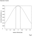
- the associated detection angle spectrum which can be detected by the optical imaging system 6 in this case, is in Fig.2 represented by the dot-dash line.
- the solid line represents the theoretically maximum possible angle spectrum, which depends solely on the aperture of the transmission system 3 and/or the optical imaging system 6.
- the normalized amplitude is represented in arbitrary units , and the relative angle in is on the x-axis Represented in radians in relation to the optical axis 7 of the optical imaging system 6 .
- the detection angle spectrum that can actually be detected is severely limited here compared to what is theoretically possible due to the requirement that it must be symmetrical to the optical axis 7 of the optical imaging system 6 .
- the device shown behaves in such a way that the object-side detection aperture cone 12 corresponds to the actually maximum possible aperture cone of the transmission system 3, the dimensions of which are specified solely by the corresponding data of an object-side lens of the transmission system 3.
- the detection aperture cone 13 can also be slightly smaller than the maximum possible aperture cone of the transmission system 3 .
- the object plane 1 in the example shown here encloses an angle with the optical axis of the transmission system 3, the amount of which is smaller than the opening angle of the object-side detection aperture cone 12 of the transmission system 3 and the object plane 1 - and thus also the plane of the light sheet 11 - At least partially within the object-side detection aperture cone 12 is located.
- the intermediate image plane 4 encloses an angle with the optical axis 5 of the transmission system 3, the amount of which is smaller than the opening angle of the intermediate image side detection aperture cone 13 of the transmission system 3, the intermediate image plane lies at least partially within the intermediate image side detection -Aperture cone 13. This is in Fig.1 clearly visible.
- the intermediate image plane 4 is therefore localized within the reflected detection aperture cone 13 .
- the optical imaging system 6 is aligned with its optical axis 7 perpendicular to the intermediate image plane 4 and collects fluorescent light at most in an image-side detection aperture cone 14, which is characterized here by the long dashed lines. Since fluorescent light or, in general, emission light, which propagates at an angle of greater than 90° relative to the optical axis 7 of the optical imaging system 6, cannot in principle be detected, the maximum theoretically possible sub-range of the detection angle spectrum in the xz plane, which is associated with the in Fig.1 shown structure can be grasped, marked by the triangle with the vertices A, B and C.
- this maximum theoretically possible partial area which is defined by the triangle ABC, is asymmetrical in relation to the optical axis 5 of the transmission system 3.
- the sub-area that can actually be captured by the optical imaging system 6 is sometimes even more restricted than the maximum theoretically possible sub-area. This depends on the aperture of the imaging optical system 6 .
- the detection angle range that can actually be detected by the optical imaging system 6 and identified by the triangle CDE covers a significantly larger angle range than the symmetrical, hatched cone according to the prior art, but is asymmetrically distributed around the optical axis 7 of the optical imaging system 6. This detection angle range, which is larger than in the prior art, results in a higher resolution of the device, even if the detection angle spectrum is distributed asymmetrically about the optical axis 7 of the optical imaging system 6 .
- the detection aperture cone 14 on the imaging side can be enlarged further if the numerical aperture of the optical imaging system 6 is also selected to be larger.
- the numerical aperture of the optical imaging system 6 is therefore preferably larger than the numerical aperture of the transmission system 3.
- a boundary surface is introduced in the intermediate image plane, which brings about a jump in the refractive index.
- a first optical medium is arranged between the optical transmission system 3 and the intermediate image plane 4 and a second optical medium is arranged between the intermediate image plane 4 and the optical imaging system 6 .
- the intermediate image plane 4 lies at the boundary between the first and second optical medium, ie in the interface.
- the second optical medium has a higher refractive index than the first optical medium.
- the optical media each cover the beam paths up to the transmission system 3 or optical imaging system 6, they can be immersion media, for example, or gel-like substances; glasses are also possible configurations.
- the sub-area that can actually be detected can be approximated as closely as possible to the theoretically possible one.
- an asymmetry remains which, in terms of imaging technology, results in an asymmetrical or non-point-symmetrical point spread function for the entire device.
- the evaluation unit 9 is preferably suitable for image processing, taking into account an asymmetrical point spread function based on the asymmetrical detection angle spectrum. In this way, the point spread function can be used for image evaluation and contribute to increasing sharpness as part of an unfolding.
- the evaluation unit is also suitable for taking into account or calculating a compressed point spread function, such as that which occurs on the described boundary surface in the intermediate image plane due to Snell's law of refraction.
- the detection angle spectra are shown for different configurations of the device.
- the images each show a section in the xz plane through the amplitude component of the light emitted by the sample, i.e. the detection angle spectrum with a solid line.
- the phase fraction is neglected in this case, which is adequate when considering fluorescence emission.
- the form of the detection angle spectrum is chosen arbitrarily and is only used for illustration.
- the abscissa represents the angle relative to the optical axis 7 of the optical imaging system 6.
- the numerical aperture of the optical transmission system 3 is 1.2 and is identical to the numerical aperture of the optical imaging system 6. Only one medium was used here, namely water with a refractive index of 1.33.
- the transmission system 3 is constructed symmetrically and the optical imaging system 6 is at an angle of 48° to the transmission system 3 in relation to the optical axes.
- the maximum theoretically possible detectable sub-range of the detection angle spectrum corresponding to triangle ABC in Fig.1 which can be detected behind the transmission system 3, is shown in dashed lines.
- this sub-range is clipped due to the aperture of the transmission system 3 and due to the fact that the intermediate image plane 4 lies within the detection aperture cone 13, to which the optical imaging system must detect perpendicularly.
- the section that can actually be detected corresponds to the triangle CDE in Fig.1 is in Figures 3-5 shown dotted.
- a further trimming results from the fact that the aperture of the optical imaging system 6 can again only cover a certain partial area, based on the optical axis 7 of the optical imaging system 6 the point spread function of the system is asymmetrical.
- the area that can actually be detected is increased by introducing a jump in the refractive index in the intermediate image plane 4 .
- Fig.5 shown here water with a refractive index of 1.33 is used as the first medium between the transmission system 3 and the intermediate image plane 4 and glass BK7 with a refractive index of 1.52 is used as the second medium between the intermediate image plane 4 and the optical imaging system.
- the numerical aperture of the optical imaging system 6 is then 1.329 and is within the realizable range due to the media selection.
- the theoretically possible spectrum is then fully recorded, it is indicated by the dotted line in Fig.5 shown.
- the resolution of the overall system can be increased if an asymmetrical, possibly compressed detection angle spectrum and, associated therewith, an asymmetrical and likewise possibly compressed point spread function are permitted during the detection.
Landscapes
- Physics & Mathematics (AREA)
- Chemical & Material Sciences (AREA)
- Analytical Chemistry (AREA)
- General Physics & Mathematics (AREA)
- Optics & Photonics (AREA)
- Engineering & Computer Science (AREA)
- Multimedia (AREA)
- Computer Vision & Pattern Recognition (AREA)
- Investigating Or Analysing Materials By Optical Means (AREA)
- Microscoopes, Condenser (AREA)
- Investigating, Analyzing Materials By Fluorescence Or Luminescence (AREA)
Applications Claiming Priority (2)
| Application Number | Priority Date | Filing Date | Title |
|---|---|---|---|
| DE102014113827.9A DE102014113827A1 (de) | 2014-09-24 | 2014-09-24 | Vorrichtung zur Abbildung einer Probe |
| PCT/EP2015/069869 WO2016045913A1 (de) | 2014-09-24 | 2015-08-31 | Vorrichtung zur abbildung einer probe |
Publications (3)
| Publication Number | Publication Date |
|---|---|
| EP3198323A1 EP3198323A1 (de) | 2017-08-02 |
| EP3198323B1 EP3198323B1 (de) | 2020-01-29 |
| EP3198323B2 true EP3198323B2 (de) | 2023-03-08 |
Family
ID=54014824
Family Applications (1)
| Application Number | Title | Priority Date | Filing Date |
|---|---|---|---|
| EP15756911.2A Active EP3198323B2 (de) | 2014-09-24 | 2015-08-31 | Vorrichtung zur abbildung einer probe |
Country Status (6)
| Country | Link |
|---|---|
| US (1) | US10477124B2 (ja) |
| EP (1) | EP3198323B2 (ja) |
| JP (1) | JP6829527B2 (ja) |
| CN (1) | CN106716217B (ja) |
| DE (1) | DE102014113827A1 (ja) |
| WO (1) | WO2016045913A1 (ja) |
Families Citing this family (3)
| Publication number | Priority date | Publication date | Assignee | Title |
|---|---|---|---|---|
| DE102016011227C5 (de) * | 2016-09-19 | 2020-04-09 | Leica Microsystems Cms Gmbh | Mikroskopsystem und Verfahren zur Abbildung einer Probe unter Verwendung eines Mikroskopsystems |
| DE102020204066A1 (de) | 2020-03-30 | 2021-09-30 | Leica Microsystems Cms Gmbh | Optische Anordnung für ein Schiefeebenenmikroskop zur Verbesserung der Auflösung |
| DE102020209889A1 (de) * | 2020-08-05 | 2022-02-10 | Carl Zeiss Microscopy Gmbh | Mikroskop und Verfahren zur mikroskopischen Bildaufnahme mit variabler Beleuchtung |
Citations (4)
| Publication number | Priority date | Publication date | Assignee | Title |
|---|---|---|---|---|
| US5004307A (en) † | 1990-04-12 | 1991-04-02 | The Board Of Trustees Of The Leland Stanford Junior University | Near field and solid immersion optical microscope |
| US20040240047A1 (en) † | 2003-02-21 | 2004-12-02 | Shafer David R. | Catadioptric imaging system for broad band microscopy |
| WO2008078083A1 (en) † | 2006-12-22 | 2008-07-03 | Isis Innovation Limited | Focusing apparatus and method |
| WO2010012980A1 (en) † | 2008-07-31 | 2010-02-04 | Imperial Innovations Limited | Optical arrangement for oblique plane microscopy |
Family Cites Families (11)
| Publication number | Priority date | Publication date | Assignee | Title |
|---|---|---|---|---|
| US498048A (en) | 1893-05-23 | Pipe-wrench | ||
| JPH0519172A (ja) * | 1991-07-09 | 1993-01-29 | Nikon Corp | レーザ走査顕微鏡 |
| JP2002054909A (ja) * | 2000-08-11 | 2002-02-20 | Dainippon Screen Mfg Co Ltd | 画像取得装置 |
| US20060291048A1 (en) * | 2001-03-19 | 2006-12-28 | Dmetrix, Inc. | Multi-axis imaging system with single-axis relay |
| DE10257423A1 (de) | 2002-12-09 | 2004-06-24 | Europäisches Laboratorium für Molekularbiologie (EMBL) | Mikroskop |
| CN1837890A (zh) * | 2006-03-29 | 2006-09-27 | 哈尔滨工业大学 | 图像复原及光瞳滤波式横向超分辨共焦显微成像方法与装置 |
| DE102011000835C5 (de) | 2011-02-21 | 2019-08-22 | Leica Microsystems Cms Gmbh | Abtastmikroskop und Verfahren zur lichtmikroskopischen Abbildung eines Objektes |
| ES2898616T3 (es) * | 2012-04-03 | 2022-03-08 | Univ Court Univ St Andrews | Imágenes de alta resolución de volúmenes extendidos |
| JP6051605B2 (ja) | 2012-06-13 | 2016-12-27 | ソニー株式会社 | 表示装置、および表示制御方法、並びにプログラム |
| DE102012013163B4 (de) | 2012-07-02 | 2022-08-25 | Carl Zeiss Microscopy Gmbh | Mikroskop und Verfahren zur Lichtscheibenmikroskopie |
| DE102013105586B4 (de) | 2013-05-30 | 2023-10-12 | Carl Zeiss Ag | Vorrichtung zur Abbildung einer Probe |
-
2014
- 2014-09-24 DE DE102014113827.9A patent/DE102014113827A1/de active Pending
-
2015
- 2015-08-31 CN CN201580051470.3A patent/CN106716217B/zh active Active
- 2015-08-31 WO PCT/EP2015/069869 patent/WO2016045913A1/de not_active Ceased
- 2015-08-31 EP EP15756911.2A patent/EP3198323B2/de active Active
- 2015-08-31 US US15/514,453 patent/US10477124B2/en active Active
- 2015-08-31 JP JP2017515697A patent/JP6829527B2/ja active Active
Patent Citations (4)
| Publication number | Priority date | Publication date | Assignee | Title |
|---|---|---|---|---|
| US5004307A (en) † | 1990-04-12 | 1991-04-02 | The Board Of Trustees Of The Leland Stanford Junior University | Near field and solid immersion optical microscope |
| US20040240047A1 (en) † | 2003-02-21 | 2004-12-02 | Shafer David R. | Catadioptric imaging system for broad band microscopy |
| WO2008078083A1 (en) † | 2006-12-22 | 2008-07-03 | Isis Innovation Limited | Focusing apparatus and method |
| WO2010012980A1 (en) † | 2008-07-31 | 2010-02-04 | Imperial Innovations Limited | Optical arrangement for oblique plane microscopy |
Non-Patent Citations (11)
| Title |
|---|
| ANSELMI ET AL.: "Three-dimensional imaging and photostimulation by remote- focusing and holographic light patterning", PNAS, vol. 108, no. 49, 6 December 2011 (2011-12-06), pages 19504 - 19509, DOI: 10.1073/pnas.1109111108 † |
| BOTCHERBY ET AL.: "An optical technique for remote focusing in microscopy", OPTICS COMMUNICATIONS, vol. 281, 2008, pages 880 - 887, DOI: 10.1016/j.optcom.2007.10.007 † |
| Broschure der Patentinhaberin aus dem Jahr 2007 † |
| C. Dunsby, "Optically sectioned imaging by oblique plane microscopy", Proc. SPIE 7367, Advanced Microscopy Techniques, 73670H, 1. Juli 2009; doi:10.1117/12.835143 † |
| DUNSBY: "Optically sectioned imaging by oblique plane microscopy", OPTICS EXPRESS, vol. 16, no. 25, 8 December 2008 (2008-12-08), pages 20306 - 20316 † |
| Internet Leica Microsystems, "Echtzeit-3D-Bildgebung lebender Organismen bei sub-zellulärer Auflösung" 08.11.2016, (gefunden 03.02.2022) † |
| KIM ET AL.: "Vectorial point spread function and optical transfer function in oblique plane imaging", OPTICS EXPRESS, vol. 22, no. 9, 1 May 2014 (2014-05-01), pages 11140 - 11151 † |
| Rechnung der Einsprechenden aus dem Jahr 2010 † |
| S. Kumar et al., "High-speed 2D and 3D fluorescence microscopy of cardiac myocytes", Optics Express, Val. 19. Seiten 13839 - 13847, 18. Juli 2011 † |
| SIBARITA: "Deconvolution Microscopy", ADVANCES IN BIOCHEMICAL ENGINEERING, vol. 95, 2005, Berlin , Heidelberg, pages 201 - 243 † |
| Stellungnahme von Prof. Dr. Dunsby † |
Also Published As
| Publication number | Publication date |
|---|---|
| JP6829527B2 (ja) | 2021-02-10 |
| US20170280076A1 (en) | 2017-09-28 |
| DE102014113827A1 (de) | 2016-03-24 |
| EP3198323B1 (de) | 2020-01-29 |
| US10477124B2 (en) | 2019-11-12 |
| JP2017530404A (ja) | 2017-10-12 |
| EP3198323A1 (de) | 2017-08-02 |
| CN106716217B (zh) | 2020-03-03 |
| CN106716217A (zh) | 2017-05-24 |
| WO2016045913A1 (de) | 2016-03-31 |
Similar Documents
| Publication | Publication Date | Title |
|---|---|---|
| EP3489735B1 (de) | Verfahren und anordnung zur lichtblattmikroskopie | |
| EP2535754B1 (de) | Abtastmikroskop und Verfahren zur lichtmikroskopischen Abbildung eines Objektes | |
| DE202014011312U1 (de) | Mikroskop, Fokussierungseinheit, Flüssigkeitshalteeinheit und optische Einheit | |
| EP3440491B1 (de) | Mikroskop und verfahren zur abbildung einer probe | |
| WO2014191381A1 (de) | Vorrichtung zur abbildung einer probe | |
| LU92925B1 (de) | Verfahren zum Untersuchen einer Probe mittels Lichtblatt-Mikroskopie und Lichtblatt-Mikroskop | |
| EP1882970A1 (de) | Laser-Scanning-Mikroskop zur Fluoreszenzuntersuchung | |
| EP3447559A1 (de) | Hochauflösende 2d-mikroskopie mit verbesserter schnittdicke | |
| WO2011018181A1 (de) | Mikroskop zur messung von totalreflexions-fluoreszenz | |
| EP3198323B2 (de) | Vorrichtung zur abbildung einer probe | |
| EP2290423B1 (de) | Scan-Mikroskop zum optische Abtasten von Proben mit einer Streuscheibe vor einem Durchlicht-Detektor | |
| EP3867861B1 (de) | Verfahren zur digitalen korrektion einer optischen abbildung einer probe mittels eines mikroskops und mikroskop | |
| WO2020207795A1 (de) | Lichtblattmikroskop und verfahren zuur bestimmung der brechungsindices von objekten im probenraum | |
| DE102014118025B4 (de) | Vorrichtung zur Lichtblattmikroskopie | |
| WO2016166374A1 (de) | Verfahren und vorrichtung zur spim-untersuchung einer probe | |
| EP3899502B1 (de) | Fluoreszenzlichtmikroskopie mit erhöhter axialer auflösung | |
| DE102011053003A1 (de) | Verfahren und Vorrichtungen zur Weitfeld-Mikroskopie | |
| EP3341781B1 (de) | Beleuchtungsanordnung für ein lichtblatt-mikroskop | |
| DE102015100695B4 (de) | Optische Anordnung für ein Laser-Scanner-System | |
| DE102018126009B4 (de) | Verfahren und Mikroskop zur Bestimmung der Dicke eines Deck- oder Tragglases | |
| DE102020204615A1 (de) | Schiefeebenemikroskop mit verbesserter Sammeleffizienz | |
| DE102023204171A1 (de) | Optisches System für ein Metrologiesystem sowie Metrologiesystem mit einem derartigen optischen System | |
| DE102022114984A1 (de) | Vorrichtung und verfahren zur lichtfeldmikroskopie | |
| DE102023204172A1 (de) | Optisches System für ein Metrologiesystem sowie Metrologiesystem mit einem derartigen optischen System | |
| LU92807B1 (de) | Beleuchtungsanordnung für ein Lichtblatt-Mikroskop |
Legal Events
| Date | Code | Title | Description |
|---|---|---|---|
| STAA | Information on the status of an ep patent application or granted ep patent |
Free format text: STATUS: THE INTERNATIONAL PUBLICATION HAS BEEN MADE |
|
| PUAI | Public reference made under article 153(3) epc to a published international application that has entered the european phase |
Free format text: ORIGINAL CODE: 0009012 |
|
| STAA | Information on the status of an ep patent application or granted ep patent |
Free format text: STATUS: REQUEST FOR EXAMINATION WAS MADE |
|
| 17P | Request for examination filed |
Effective date: 20170403 |
|
| AK | Designated contracting states |
Kind code of ref document: A1 Designated state(s): AL AT BE BG CH CY CZ DE DK EE ES FI FR GB GR HR HU IE IS IT LI LT LU LV MC MK MT NL NO PL PT RO RS SE SI SK SM TR |
|
| AX | Request for extension of the european patent |
Extension state: BA ME |
|
| DAV | Request for validation of the european patent (deleted) | ||
| DAX | Request for extension of the european patent (deleted) | ||
| GRAP | Despatch of communication of intention to grant a patent |
Free format text: ORIGINAL CODE: EPIDOSNIGR1 |
|
| STAA | Information on the status of an ep patent application or granted ep patent |
Free format text: STATUS: GRANT OF PATENT IS INTENDED |
|
| INTG | Intention to grant announced |
Effective date: 20191004 |
|
| GRAS | Grant fee paid |
Free format text: ORIGINAL CODE: EPIDOSNIGR3 |
|
| GRAA | (expected) grant |
Free format text: ORIGINAL CODE: 0009210 |
|
| STAA | Information on the status of an ep patent application or granted ep patent |
Free format text: STATUS: THE PATENT HAS BEEN GRANTED |
|
| RIN1 | Information on inventor provided before grant (corrected) |
Inventor name: WOLLESCHENSKY, RALF Inventor name: SIEBENMORGEN, JOERG Inventor name: KALKBRENNER, THOMAS Inventor name: KLEPPE, INGO Inventor name: LIPPERT, HELMUT |
|
| AK | Designated contracting states |
Kind code of ref document: B1 Designated state(s): AL AT BE BG CH CY CZ DE DK EE ES FI FR GB GR HR HU IE IS IT LI LT LU LV MC MK MT NL NO PL PT RO RS SE SI SK SM TR |
|
| REG | Reference to a national code |
Ref country code: GB Ref legal event code: FG4D Free format text: NOT ENGLISH |
|
| REG | Reference to a national code |
Ref country code: CH Ref legal event code: EP |
|
| REG | Reference to a national code |
Ref country code: AT Ref legal event code: REF Ref document number: 1228878 Country of ref document: AT Kind code of ref document: T Effective date: 20200215 |
|
| REG | Reference to a national code |
Ref country code: IE Ref legal event code: FG4D Free format text: LANGUAGE OF EP DOCUMENT: GERMAN |
|
| REG | Reference to a national code |
Ref country code: DE Ref legal event code: R096 Ref document number: 502015011606 Country of ref document: DE |
|
| REG | Reference to a national code |
Ref country code: NL Ref legal event code: MP Effective date: 20200129 |
|
| PG25 | Lapsed in a contracting state [announced via postgrant information from national office to epo] |
Ref country code: FI Free format text: LAPSE BECAUSE OF FAILURE TO SUBMIT A TRANSLATION OF THE DESCRIPTION OR TO PAY THE FEE WITHIN THE PRESCRIBED TIME-LIMIT Effective date: 20200129 Ref country code: RS Free format text: LAPSE BECAUSE OF FAILURE TO SUBMIT A TRANSLATION OF THE DESCRIPTION OR TO PAY THE FEE WITHIN THE PRESCRIBED TIME-LIMIT Effective date: 20200129 Ref country code: NO Free format text: LAPSE BECAUSE OF FAILURE TO SUBMIT A TRANSLATION OF THE DESCRIPTION OR TO PAY THE FEE WITHIN THE PRESCRIBED TIME-LIMIT Effective date: 20200429 Ref country code: PT Free format text: LAPSE BECAUSE OF FAILURE TO SUBMIT A TRANSLATION OF THE DESCRIPTION OR TO PAY THE FEE WITHIN THE PRESCRIBED TIME-LIMIT Effective date: 20200621 |
|
| REG | Reference to a national code |
Ref country code: LT Ref legal event code: MG4D |
|
| PG25 | Lapsed in a contracting state [announced via postgrant information from national office to epo] |
Ref country code: GR Free format text: LAPSE BECAUSE OF FAILURE TO SUBMIT A TRANSLATION OF THE DESCRIPTION OR TO PAY THE FEE WITHIN THE PRESCRIBED TIME-LIMIT Effective date: 20200430 Ref country code: BG Free format text: LAPSE BECAUSE OF FAILURE TO SUBMIT A TRANSLATION OF THE DESCRIPTION OR TO PAY THE FEE WITHIN THE PRESCRIBED TIME-LIMIT Effective date: 20200429 Ref country code: HR Free format text: LAPSE BECAUSE OF FAILURE TO SUBMIT A TRANSLATION OF THE DESCRIPTION OR TO PAY THE FEE WITHIN THE PRESCRIBED TIME-LIMIT Effective date: 20200129 Ref country code: LV Free format text: LAPSE BECAUSE OF FAILURE TO SUBMIT A TRANSLATION OF THE DESCRIPTION OR TO PAY THE FEE WITHIN THE PRESCRIBED TIME-LIMIT Effective date: 20200129 Ref country code: SE Free format text: LAPSE BECAUSE OF FAILURE TO SUBMIT A TRANSLATION OF THE DESCRIPTION OR TO PAY THE FEE WITHIN THE PRESCRIBED TIME-LIMIT Effective date: 20200129 Ref country code: IS Free format text: LAPSE BECAUSE OF FAILURE TO SUBMIT A TRANSLATION OF THE DESCRIPTION OR TO PAY THE FEE WITHIN THE PRESCRIBED TIME-LIMIT Effective date: 20200529 |
|
| PG25 | Lapsed in a contracting state [announced via postgrant information from national office to epo] |
Ref country code: NL Free format text: LAPSE BECAUSE OF FAILURE TO SUBMIT A TRANSLATION OF THE DESCRIPTION OR TO PAY THE FEE WITHIN THE PRESCRIBED TIME-LIMIT Effective date: 20200129 |
|
| REG | Reference to a national code |
Ref country code: DE Ref legal event code: R026 Ref document number: 502015011606 Country of ref document: DE |
|
| PG25 | Lapsed in a contracting state [announced via postgrant information from national office to epo] |
Ref country code: LT Free format text: LAPSE BECAUSE OF FAILURE TO SUBMIT A TRANSLATION OF THE DESCRIPTION OR TO PAY THE FEE WITHIN THE PRESCRIBED TIME-LIMIT Effective date: 20200129 Ref country code: EE Free format text: LAPSE BECAUSE OF FAILURE TO SUBMIT A TRANSLATION OF THE DESCRIPTION OR TO PAY THE FEE WITHIN THE PRESCRIBED TIME-LIMIT Effective date: 20200129 Ref country code: SM Free format text: LAPSE BECAUSE OF FAILURE TO SUBMIT A TRANSLATION OF THE DESCRIPTION OR TO PAY THE FEE WITHIN THE PRESCRIBED TIME-LIMIT Effective date: 20200129 Ref country code: DK Free format text: LAPSE BECAUSE OF FAILURE TO SUBMIT A TRANSLATION OF THE DESCRIPTION OR TO PAY THE FEE WITHIN THE PRESCRIBED TIME-LIMIT Effective date: 20200129 Ref country code: CZ Free format text: LAPSE BECAUSE OF FAILURE TO SUBMIT A TRANSLATION OF THE DESCRIPTION OR TO PAY THE FEE WITHIN THE PRESCRIBED TIME-LIMIT Effective date: 20200129 Ref country code: RO Free format text: LAPSE BECAUSE OF FAILURE TO SUBMIT A TRANSLATION OF THE DESCRIPTION OR TO PAY THE FEE WITHIN THE PRESCRIBED TIME-LIMIT Effective date: 20200129 Ref country code: SK Free format text: LAPSE BECAUSE OF FAILURE TO SUBMIT A TRANSLATION OF THE DESCRIPTION OR TO PAY THE FEE WITHIN THE PRESCRIBED TIME-LIMIT Effective date: 20200129 Ref country code: ES Free format text: LAPSE BECAUSE OF FAILURE TO SUBMIT A TRANSLATION OF THE DESCRIPTION OR TO PAY THE FEE WITHIN THE PRESCRIBED TIME-LIMIT Effective date: 20200129 |
|
| PLBI | Opposition filed |
Free format text: ORIGINAL CODE: 0009260 |
|
| PLAX | Notice of opposition and request to file observation + time limit sent |
Free format text: ORIGINAL CODE: EPIDOSNOBS2 |
|
| 26 | Opposition filed |
Opponent name: LEICA MICROSYSTEMS CMS GMBH Effective date: 20201027 |
|
| PG25 | Lapsed in a contracting state [announced via postgrant information from national office to epo] |
Ref country code: IT Free format text: LAPSE BECAUSE OF FAILURE TO SUBMIT A TRANSLATION OF THE DESCRIPTION OR TO PAY THE FEE WITHIN THE PRESCRIBED TIME-LIMIT Effective date: 20200129 |
|
| PG25 | Lapsed in a contracting state [announced via postgrant information from national office to epo] |
Ref country code: SI Free format text: LAPSE BECAUSE OF FAILURE TO SUBMIT A TRANSLATION OF THE DESCRIPTION OR TO PAY THE FEE WITHIN THE PRESCRIBED TIME-LIMIT Effective date: 20200129 Ref country code: PL Free format text: LAPSE BECAUSE OF FAILURE TO SUBMIT A TRANSLATION OF THE DESCRIPTION OR TO PAY THE FEE WITHIN THE PRESCRIBED TIME-LIMIT Effective date: 20200129 |
|
| PLBB | Reply of patent proprietor to notice(s) of opposition received |
Free format text: ORIGINAL CODE: EPIDOSNOBS3 |
|
| PG25 | Lapsed in a contracting state [announced via postgrant information from national office to epo] |
Ref country code: MC Free format text: LAPSE BECAUSE OF FAILURE TO SUBMIT A TRANSLATION OF THE DESCRIPTION OR TO PAY THE FEE WITHIN THE PRESCRIBED TIME-LIMIT Effective date: 20200129 |
|
| REG | Reference to a national code |
Ref country code: CH Ref legal event code: PL |
|
| PG25 | Lapsed in a contracting state [announced via postgrant information from national office to epo] |
Ref country code: LU Free format text: LAPSE BECAUSE OF NON-PAYMENT OF DUE FEES Effective date: 20200831 Ref country code: LI Free format text: LAPSE BECAUSE OF NON-PAYMENT OF DUE FEES Effective date: 20200831 Ref country code: CH Free format text: LAPSE BECAUSE OF NON-PAYMENT OF DUE FEES Effective date: 20200831 |
|
| REG | Reference to a national code |
Ref country code: BE Ref legal event code: MM Effective date: 20200831 |
|
| PG25 | Lapsed in a contracting state [announced via postgrant information from national office to epo] |
Ref country code: FR Free format text: LAPSE BECAUSE OF NON-PAYMENT OF DUE FEES Effective date: 20200831 |
|
| PG25 | Lapsed in a contracting state [announced via postgrant information from national office to epo] |
Ref country code: BE Free format text: LAPSE BECAUSE OF NON-PAYMENT OF DUE FEES Effective date: 20200831 Ref country code: IE Free format text: LAPSE BECAUSE OF NON-PAYMENT OF DUE FEES Effective date: 20200831 |
|
| REG | Reference to a national code |
Ref country code: AT Ref legal event code: MM01 Ref document number: 1228878 Country of ref document: AT Kind code of ref document: T Effective date: 20200831 |
|
| PG25 | Lapsed in a contracting state [announced via postgrant information from national office to epo] |
Ref country code: AT Free format text: LAPSE BECAUSE OF NON-PAYMENT OF DUE FEES Effective date: 20200831 |
|
| PG25 | Lapsed in a contracting state [announced via postgrant information from national office to epo] |
Ref country code: TR Free format text: LAPSE BECAUSE OF FAILURE TO SUBMIT A TRANSLATION OF THE DESCRIPTION OR TO PAY THE FEE WITHIN THE PRESCRIBED TIME-LIMIT Effective date: 20200129 Ref country code: MT Free format text: LAPSE BECAUSE OF FAILURE TO SUBMIT A TRANSLATION OF THE DESCRIPTION OR TO PAY THE FEE WITHIN THE PRESCRIBED TIME-LIMIT Effective date: 20200129 Ref country code: CY Free format text: LAPSE BECAUSE OF FAILURE TO SUBMIT A TRANSLATION OF THE DESCRIPTION OR TO PAY THE FEE WITHIN THE PRESCRIBED TIME-LIMIT Effective date: 20200129 |
|
| PG25 | Lapsed in a contracting state [announced via postgrant information from national office to epo] |
Ref country code: MK Free format text: LAPSE BECAUSE OF FAILURE TO SUBMIT A TRANSLATION OF THE DESCRIPTION OR TO PAY THE FEE WITHIN THE PRESCRIBED TIME-LIMIT Effective date: 20200129 Ref country code: AL Free format text: LAPSE BECAUSE OF FAILURE TO SUBMIT A TRANSLATION OF THE DESCRIPTION OR TO PAY THE FEE WITHIN THE PRESCRIBED TIME-LIMIT Effective date: 20200129 |
|
| PUAH | Patent maintained in amended form |
Free format text: ORIGINAL CODE: 0009272 |
|
| STAA | Information on the status of an ep patent application or granted ep patent |
Free format text: STATUS: PATENT MAINTAINED AS AMENDED |
|
| 27A | Patent maintained in amended form |
Effective date: 20230308 |
|
| AK | Designated contracting states |
Kind code of ref document: B2 Designated state(s): AL AT BE BG CH CY CZ DE DK EE ES FI FR GB GR HR HU IE IS IT LI LT LU LV MC MK MT NL NO PL PT RO RS SE SI SK SM TR |
|
| REG | Reference to a national code |
Ref country code: DE Ref legal event code: R102 Ref document number: 502015011606 Country of ref document: DE |
|
| REG | Reference to a national code |
Ref country code: DE Ref legal event code: R082 Ref document number: 502015011606 Country of ref document: DE Representative=s name: GLEIM PETRI PATENT- UND RECHTSANWALTSPARTNERSC, DE |
|
| PGFP | Annual fee paid to national office [announced via postgrant information from national office to epo] |
Ref country code: DE Payment date: 20250820 Year of fee payment: 11 |
|
| PGFP | Annual fee paid to national office [announced via postgrant information from national office to epo] |
Ref country code: GB Payment date: 20250821 Year of fee payment: 11 |