EP3199314B1 - Strangerzeugungsvorrichtung und darauf bezogene granuliervorrichtung - Google Patents
Strangerzeugungsvorrichtung und darauf bezogene granuliervorrichtung Download PDFInfo
- Publication number
- EP3199314B1 EP3199314B1 EP16152944.1A EP16152944A EP3199314B1 EP 3199314 B1 EP3199314 B1 EP 3199314B1 EP 16152944 A EP16152944 A EP 16152944A EP 3199314 B1 EP3199314 B1 EP 3199314B1
- Authority
- EP
- European Patent Office
- Prior art keywords
- reinforcing
- production device
- perforated plate
- strand production
- struts
- Prior art date
- Legal status (The legal status is an assumption and is not a legal conclusion. Google has not performed a legal analysis and makes no representation as to the accuracy of the status listed.)
- Active
Links
Images



Classifications
-
- B—PERFORMING OPERATIONS; TRANSPORTING
- B29—WORKING OF PLASTICS; WORKING OF SUBSTANCES IN A PLASTIC STATE IN GENERAL
- B29B—PREPARATION OR PRETREATMENT OF THE MATERIAL TO BE SHAPED; MAKING GRANULES OR PREFORMS; RECOVERY OF PLASTICS OR OTHER CONSTITUENTS OF WASTE MATERIAL CONTAINING PLASTICS
- B29B9/00—Making granules
- B29B9/02—Making granules by dividing preformed material
- B29B9/06—Making granules by dividing preformed material in the form of filamentary material, e.g. combined with extrusion
-
- B—PERFORMING OPERATIONS; TRANSPORTING
- B01—PHYSICAL OR CHEMICAL PROCESSES OR APPARATUS IN GENERAL
- B01J—CHEMICAL OR PHYSICAL PROCESSES, e.g. CATALYSIS OR COLLOID CHEMISTRY; THEIR RELEVANT APPARATUS
- B01J2/00—Processes or devices for granulating materials, e.g. fertilisers in general; Rendering particulate materials free flowing in general, e.g. making them hydrophobic
- B01J2/20—Processes or devices for granulating materials, e.g. fertilisers in general; Rendering particulate materials free flowing in general, e.g. making them hydrophobic by expressing the material, e.g. through sieves and fragmenting the extruded length
-
- B—PERFORMING OPERATIONS; TRANSPORTING
- B29—WORKING OF PLASTICS; WORKING OF SUBSTANCES IN A PLASTIC STATE IN GENERAL
- B29B—PREPARATION OR PRETREATMENT OF THE MATERIAL TO BE SHAPED; MAKING GRANULES OR PREFORMS; RECOVERY OF PLASTICS OR OTHER CONSTITUENTS OF WASTE MATERIAL CONTAINING PLASTICS
- B29B7/00—Mixing; Kneading
- B29B7/30—Mixing; Kneading continuous, with mechanical mixing or kneading devices
- B29B7/58—Component parts, details or accessories; Auxiliary operations
- B29B7/582—Component parts, details or accessories; Auxiliary operations for discharging, e.g. doors
-
- B—PERFORMING OPERATIONS; TRANSPORTING
- B29—WORKING OF PLASTICS; WORKING OF SUBSTANCES IN A PLASTIC STATE IN GENERAL
- B29B—PREPARATION OR PRETREATMENT OF THE MATERIAL TO BE SHAPED; MAKING GRANULES OR PREFORMS; RECOVERY OF PLASTICS OR OTHER CONSTITUENTS OF WASTE MATERIAL CONTAINING PLASTICS
- B29B7/00—Mixing; Kneading
- B29B7/80—Component parts, details or accessories; Auxiliary operations
- B29B7/82—Heating or cooling
- B29B7/826—Apparatus therefor
-
- B—PERFORMING OPERATIONS; TRANSPORTING
- B29—WORKING OF PLASTICS; WORKING OF SUBSTANCES IN A PLASTIC STATE IN GENERAL
- B29C—SHAPING OR JOINING OF PLASTICS; SHAPING OF MATERIAL IN A PLASTIC STATE, NOT OTHERWISE PROVIDED FOR; AFTER-TREATMENT OF THE SHAPED PRODUCTS, e.g. REPAIRING
- B29C48/00—Extrusion moulding, i.e. expressing the moulding material through a die or nozzle which imparts the desired form; Apparatus therefor
- B29C48/03—Extrusion moulding, i.e. expressing the moulding material through a die or nozzle which imparts the desired form; Apparatus therefor characterised by the shape of the extruded material at extrusion
- B29C48/05—Filamentary, e.g. strands
-
- B—PERFORMING OPERATIONS; TRANSPORTING
- B29—WORKING OF PLASTICS; WORKING OF SUBSTANCES IN A PLASTIC STATE IN GENERAL
- B29C—SHAPING OR JOINING OF PLASTICS; SHAPING OF MATERIAL IN A PLASTIC STATE, NOT OTHERWISE PROVIDED FOR; AFTER-TREATMENT OF THE SHAPED PRODUCTS, e.g. REPAIRING
- B29C48/00—Extrusion moulding, i.e. expressing the moulding material through a die or nozzle which imparts the desired form; Apparatus therefor
- B29C48/25—Component parts, details or accessories; Auxiliary operations
- B29C48/30—Extrusion nozzles or dies
- B29C48/345—Extrusion nozzles comprising two or more adjacently arranged ports, for simultaneously extruding multiple strands, e.g. for pelletising
-
- B—PERFORMING OPERATIONS; TRANSPORTING
- B29—WORKING OF PLASTICS; WORKING OF SUBSTANCES IN A PLASTIC STATE IN GENERAL
- B29C—SHAPING OR JOINING OF PLASTICS; SHAPING OF MATERIAL IN A PLASTIC STATE, NOT OTHERWISE PROVIDED FOR; AFTER-TREATMENT OF THE SHAPED PRODUCTS, e.g. REPAIRING
- B29C48/00—Extrusion moulding, i.e. expressing the moulding material through a die or nozzle which imparts the desired form; Apparatus therefor
- B29C48/25—Component parts, details or accessories; Auxiliary operations
- B29C48/78—Thermal treatment of the extrusion moulding material or of preformed parts or layers, e.g. by heating or cooling
- B29C48/86—Thermal treatment of the extrusion moulding material or of preformed parts or layers, e.g. by heating or cooling at the nozzle zone
- B29C48/865—Heating
-
- B—PERFORMING OPERATIONS; TRANSPORTING
- B29—WORKING OF PLASTICS; WORKING OF SUBSTANCES IN A PLASTIC STATE IN GENERAL
- B29C—SHAPING OR JOINING OF PLASTICS; SHAPING OF MATERIAL IN A PLASTIC STATE, NOT OTHERWISE PROVIDED FOR; AFTER-TREATMENT OF THE SHAPED PRODUCTS, e.g. REPAIRING
- B29C2793/00—Shaping techniques involving a cutting or machining operation
- B29C2793/0027—Cutting off
-
- B—PERFORMING OPERATIONS; TRANSPORTING
- B29—WORKING OF PLASTICS; WORKING OF SUBSTANCES IN A PLASTIC STATE IN GENERAL
- B29C—SHAPING OR JOINING OF PLASTICS; SHAPING OF MATERIAL IN A PLASTIC STATE, NOT OTHERWISE PROVIDED FOR; AFTER-TREATMENT OF THE SHAPED PRODUCTS, e.g. REPAIRING
- B29C48/00—Extrusion moulding, i.e. expressing the moulding material through a die or nozzle which imparts the desired form; Apparatus therefor
- B29C48/001—Combinations of extrusion moulding with other shaping operations
- B29C48/0022—Combinations of extrusion moulding with other shaping operations combined with cutting
-
- B—PERFORMING OPERATIONS; TRANSPORTING
- B29—WORKING OF PLASTICS; WORKING OF SUBSTANCES IN A PLASTIC STATE IN GENERAL
- B29C—SHAPING OR JOINING OF PLASTICS; SHAPING OF MATERIAL IN A PLASTIC STATE, NOT OTHERWISE PROVIDED FOR; AFTER-TREATMENT OF THE SHAPED PRODUCTS, e.g. REPAIRING
- B29C48/00—Extrusion moulding, i.e. expressing the moulding material through a die or nozzle which imparts the desired form; Apparatus therefor
- B29C48/03—Extrusion moulding, i.e. expressing the moulding material through a die or nozzle which imparts the desired form; Apparatus therefor characterised by the shape of the extruded material at extrusion
- B29C48/04—Particle-shaped
Definitions
- the invention relates to a strand generating device for producing granular material strands according to the preamble of claim 1. Furthermore, the invention relates to a granulating device for a screw machine with such a strand generating device.
- a granulating device for a screw machine is known.
- the material to be granulated is processed in the screw machine and then conveyed through a perforated plate, so that granular material strands are produced.
- the material strands are granulated by means of rotating cutting knives.
- the perforated plate is heated.
- a heated perforated plate are used in the electric heating cartridges in holes of the perforated plate.
- the heating cartridges can be arranged axially parallel or radially in the perforated plate.
- a granulating head of an underwater pelletizer is known.
- the plastic melt is first divided on the inlet side of the granulating head by means of a cone into several partial streams. Through channels that are formed in a base member, the melt streams pass through holes in a perforated plate.
- the base component is heated by means of heating cartridges, so that the plastic melt does not solidify in the channels.
- the underwater granulator has a nozzle plate attached to a back wall with melt channels.
- the nozzle plate is tempered by means of a tempering fluid.
- the tempering fluid is accommodated in a cavity and is heated by means of heating cartridges.
- the granulator has a nozzle plate which is fixed to an extruder housing. In the nozzle plate radially extending recesses are formed in which heating elements are arranged.
- the granulating device has an inlet housing, which divides the plastic melt into a plurality of partial flows and leads to a perforated plate.
- a perforated plate In the perforated plate radially extending recesses are formed, which serve to receive electrical heating elements.
- the invention has for its object to provide a strand generating device for producing granulated material strands, which allows in a simple manner a uniform heating of a perforated plate and a low pressure drop of the material flowing through the perforated plate.
- the at least one perforated plate has a small thickness in the flow direction of the material strands-producing material, so that the at least one perforated plate produces a comparatively low pressure loss of the material. Due to the reinforcing support, the at least one perforated plate nevertheless has sufficient mechanical strength.
- the reinforcing support has a greater thickness than the at least one perforated plate in the flow direction, so that the reinforcing support can receive the at least one electric heating cartridge.
- at least one receiving space is formed in the reinforcing member, in which the at least one heating cartridge is arranged.
- the heating cartridge is in particular in thermal contact with the reinforcing member and is for example closely against the reinforcing member.
- the reinforcing support is in particular made of a material with a high thermal conductivity, so that the heat generated by the at least one heating cartridge is transmitted to the at least one perforated plate in a simple manner via the reinforcing carrier and distributed.
- the at least one perforated plate and the reinforcement carrier are for example formed separately from one another, ie as separate components, so that the at least one perforated plate is arranged and supported on the reinforcing carrier.
- the at least one perforated plate and the reinforcing member are formed, for example, as a one-piece component.
- the one-piece design high rigidity and strength and high thermal conductivity is achieved.
- the strand generating device easily ensures uniform heating in conjunction with a low pressure loss. Due to the reinforcing struts, the reinforcing carrier on the one hand large free passage areas, which are available for the arrangement of at least one perforated plate. On the other hand, the reinforcing struts allow a simple support of the at least one perforated plate in conjunction with a large-area distribution and transfer of the heat generated by the at least one heating cartridge on the at least one perforated plate.
- the strand generating device ensures in a simple manner a uniform heating of at least one perforated plate. Characterized in that the at least one receiving space is formed in an associated reinforcing strut, the heat generated by the at least one heating cartridge is distributed over the reinforcing strut transferred to the at least one perforated plate. Characterized in that the at least one receiving space is formed in the longitudinal direction of the reinforcing strut, a heating cartridge with a high heating power is receivable and the heat generated over the associated reinforcing strut easily distributed and transferable.
- a strand generating device ensures in a simple manner a uniform heating in conjunction with a low pressure loss.
- the reinforcing struts are arranged radially to the central longitudinal axis of the strand generating device.
- the reinforcing struts are interconnected with a respective inner end facing the central longitudinal axis.
- the reinforcing struts are thus arranged in a star-like manner and, in particular, have equal angular distances from one another.
- the reinforcing struts are integrally formed with each other.
- a strand generating device ensures in a simple manner a uniform heating in conjunction with a low pressure loss.
- the reinforcing struts are connected to each other at the end, the reinforcing carrier has a high mechanical strength or rigidity and thus makes it possible to provide large free passage areas for strand production by means of the at least one perforated plate.
- the reinforcing struts are integrally connected.
- the reinforcing struts are preferably arranged radially and connected to each other at an inner end facing the central longitudinal axis and / or connected to each other at a respective outer end remote from the central longitudinal axis by means of connecting struts.
- the connecting struts are formed for example in the form of a circular arc. Between two adjacent stiffening struts, a free passage region of the reinforcement carrier is formed.
- the passage region is formed in particular circular sector-shaped or triangular.
- a strand generating device ensures in a simple manner a uniform heating in conjunction with a low pressure loss. Due to the number of reinforcing struts, the mechanical strength, the free passage areas and the heat distribution or the heat transfer to the at least one perforated plate are adjustable.
- a strand generating device ensures in a simple manner a uniform heating.
- the at least one perforated plate is, in particular from the downstream side, inserted into the reinforcing member and abuts against an associated reinforcing member stop.
- the at least one perforated plate is replaceable on the reinforcement carrier attached.
- the at least one perforated plate forms, in particular together with the reinforcing support, on the downstream side a flat surface for at least one cutting blade of a granulating device.
- a strand generating device ensures a low pressure loss. Due to the fact that the reinforcement carrier, in particular the reinforcing struts, at least in sections have a cross-section which tapers in the direction of the upstream side, the reinforcing carrier has a low flow resistance for the flowing material.
- a strand generating device ensures in a simple manner a low pressure loss.
- the fact that the at least one perforated plate in the flow direction has a small thickness D 1 compared to the thickness D 2 of the reinforcing struts causes the at least one perforated plate a low pressure loss.
- the mechanical strength of the at least one perforated plate is nevertheless ensured by the reinforcing struts.
- a strand generating device ensures a uniform heating of the at least one perforated plate. Due to the extent of the at least one heating cartridge, the heat generated in a simple manner in the radial direction on the reinforcing support on the at least one perforated plate and distributed transferable.
- a strand generating device ensures in a simple manner an extremely uniform heating of at least one perforated plate.
- the heating capacity of the at least one heating cartridge varies along its longitudinal direction and decreases in particular along its longitudinal direction from the free end down.
- the heating power of the at least one heating cartridge along its longitudinal direction is adjustable.
- the mass to be heated of the at least one perforated plate decreases in the direction of the central longitudinal axis.
- the at least one heating element in the direction of the central longitudinal axis in particular has a decreasing heating power, the heating power is adapted in a simple manner to the mass to be heated.
- the at least one heating cartridge is designed, for example, such that it has a plurality of heating regions with different heating power in their longitudinal direction.
- the heating power is adjustable in each of the heating areas.
- a strand generating device ensures in a simple manner a uniform heating of the perforated plates. Characterized in that a plurality of perforated plates are arranged on the reinforcing member, the respective perforated plate is easier and faster heatable. In addition, the respective perforated plate is easier to produce.
- the number M of the perforated plates is equal to the number N of the reinforcing struts, so that a perforated plate is in each case arranged in the free passage region between two adjacent reinforcing struts.
- a strand generating device ensures in a simple manner a fast and uniform heating of the perforated plate.
- the invention is further based on the object to provide a granulator for a screw machine, which allows a uniform heating of a perforated plate and a low pressure drop of the material flowing through the perforated plate in a simple manner.
- a granulating device with the features of claim 12.
- the advantages of the granulating device according to the invention correspond to the already described advantages of the strand generating device according to the invention.
- the at least one cutting blade bears in particular against the at least one perforated plate, so that the material strands emerging from the through-holes directly be cut by the at least one rotary-driven cutting blade to granules.
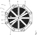
- a granulating device 1 for a screw machine comprises a strand generating device 2 and a knife carrier 3 with a plurality of cutting blades 4 arranged thereon.
- the knife carrier 3 with the Cutting knives 4 is arranged in a flow direction 5 of a material 6 to be granulated on a downstream side 7 of the strand generating device 2.
- the knife carrier 3 with the cutting blades 4 is rotatably drivable in the usual manner about a central longitudinal axis 8 by means of an electric drive motor, not shown.
- the knife carrier 3 with the cutting blades 4 can be displaced in the usual way in the direction of the central longitudinal axis 8, so that the cutting blades 4 can be arranged in abutment against the strand generating device 2 for operation of the granulating device 1.
- the strand generating device 2 serves to produce granular material strands 9 of the material 6 by flowing from an upstream side 10 through the strand generating device 2 to the downstream side 7.
- the strand generating device 2 has a plurality of perforated plates 11, which are arranged on a reinforcing support 12.
- the perforated plates 11 have a respective base plate 13 in which a plurality of through holes 14 are formed extending from the upstream side 10 to the downstream side 7.
- the passage holes 14 form a respective flow channel for the material 6, which has a conical inlet section and a subsequent cylindrical flow section.
- the reinforcing beam 12 comprises a plurality of reinforcing struts 15, which extend radially to the central longitudinal axis 8.
- the reinforcing struts 15 are arranged in a star shape and have equal angular distances from each other.
- the reinforcing struts 15 are integrally connected to each other at one of the central longitudinal axis 8 facing inner end 16.
- the reinforcing struts 15 are integrally via connecting struts 18 connected with each other.
- the connecting struts 18 are formed on a side facing the central longitudinal axis 8 as a circular arc.
- Neighboring reinforcing struts 15 define in pairs a respective associated free passage area 19.
- the free passage areas 19 are designed tapering in the direction of the central longitudinal axis 8. Due to the circular arc-shaped design of the connecting struts 18, the passage areas 19 have the shape of a circular sector.
- the perforated plates 11 are shaped according to the free passage areas 19.
- the perforated plates 11 are inserted from the downstream side 7 into recesses 20 of the reinforcing carrier 12, so that the perforated plates 11 with the reinforcing carrier 12 and the reinforcing struts 15 form a flat surface.
- the perforated plates 11 abut against a reinforcing carrier stop of the reinforcing carrier 12 in an edge region and are fastened interchangeably to the reinforcing carrier 12.
- the reinforcing struts 15 have a tapering in the direction of the upstream side 10 cross-section.
- the reinforcing struts 15 are preferably wedge-shaped.
- a number N of the reinforcing struts 15 is equal to a number M of the perforated plates 11.
- an integrally formed perforated plate 11 is disposed between each two adjacent reinforcing struts 15.
- the passage holes 14 of the respective perforated plate 11 are formed essentially in the entire associated passage area 19.
- N 8.
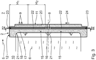
- the perforated plates 11 have a thickness D 1 in the region of the through-holes 14 in the flow direction 5. Furthermore, the reinforcement struts 15 have a thickness D 2 outside of a connection region 21 to the connection struts 18 in the flow direction 5.
- D 1 / D 2 is generally: 0.05 ⁇ D 1 / D 2 ⁇ 0.5, in particular 0.1 ⁇ D 1 / D 2 ⁇ 0.4, and in particular 0.15 ⁇ D 1 / D 2 ⁇ 0.3.
- the strand generating device 2 For heating the perforated plates 11, the strand generating device 2 has electric heating cartridges 22.
- the heating cartridges 22 are arranged in a respectively associated receiving space 23.
- the receiving spaces 23 are formed in the reinforcing carrier 12.
- a number K of the heating cartridges 22 corresponds to the number N of the reinforcing struts 15.
- each reinforcing strut 15 is thus formed a receiving space 23 which extends in a respective longitudinal direction 24 of the associated reinforcing strut 15, that extends radially.
- the associated heating cartridge 22 is arranged, which also extends in the longitudinal direction 24, ie radially.
- the heating cartridges 22 each have a heating power, which varies in the longitudinal direction of extension 24, ie in the direction of the central longitudinal axis 8, in particular decreases.
- the respective heating cartridge 22 for example, a heating circuit or more heating circuits with a variable and in particular adjustable heating power.
- the heating cartridges 22 form two heating areas H 1 and H 2 with different heating powers.
- the heating power in the heating area H 2 is smaller than the heating power in the heating area H 1 in the present embodiment.
- the Heating range H 1 has, for example, a heating power of 260 W, whereas heating range H 2 has a heating power of 130 W.
- each heating cartridge 22 thus has, for example, a heating power of 390 W, so that the perforated plates 11 can be heated with a total heating power of 3,120 W.
- the heating area H 1 and H 2 have a total length of, for example, 180 mm.
- the flowing material 6 is provided by a screw machine, which is arranged upstream of the granulating device 1.
- the material 6 flows from the upstream side 10 through the through holes 14 of the perforated plates 11, so that the material strands 9 are formed on the downstream side 7 of the perforated plates 11. This is in Fig. 3 indicated.
- the perforated plates 11 are heated by means of the heating cartridges 22.
- the heat generated by the heating cartridges 22 is distributed over the reinforcing struts 15 on the perforated plates 11 and transmitted.
- the perforated plates 11 are heated comparatively uniformly, since the mass to be heated of the perforated plates 11 decreases due to their shape in the direction of the central longitudinal axis 8. Furthermore, the material 6 on the upstream side 10 is additionally heated by the reinforcing member 12.
- the perforated plates 11 Due to the arrangement of the perforated plates 11 on the reinforcing member 12, the perforated plates 11 are formed with a small thickness D 1 , without their mechanical strength or rigidity is impaired. hereby the perforated plates 11 have a low flow resistance for the material 6, so that the pressure loss of the material 6 when flowing through the strand generating device 2 is low. In addition, the flow resistance of the reinforcing struts 15 is reduced by the wedge-shaped cross section, so that the reinforcing carrier 12 also causes a comparatively low pressure loss of the material 6.
- the material strands 9 produced are cut in a conventional manner by means of the rotating cutting blades 4, so that granules 9 are produced on the downstream side 7 from the material strands.
- the granulating device 1 or the strand generating device 2 thus enables in a simple manner a uniform heating of the perforated plates 11 in conjunction with a low pressure loss of the material 6 flowing through the perforated plates 11.
- a single orifice plate 11 may be disposed on the reinforcement beam 12 and form a flat surface for the at least one cutting blade 4.
- the perforated plate 11 or the perforated plates 11 and the reinforcing carrier 12 may be integrally formed.
Landscapes
- Engineering & Computer Science (AREA)
- Mechanical Engineering (AREA)
- Physics & Mathematics (AREA)
- Thermal Sciences (AREA)
- Manufacturing & Machinery (AREA)
- Chemical & Material Sciences (AREA)
- Organic Chemistry (AREA)
- Chemical Kinetics & Catalysis (AREA)
- Processing And Handling Of Plastics And Other Materials For Molding In General (AREA)
Description
- Die Erfindung betrifft eine Strangerzeugungsvorrichtung zum Erzeugen granulierbarer Materialstränge gemäß dem Oberbegriff des Anspruchs 1. Ferner betrifft die Erfindung eine Granuliervorrichtung für eine Schneckenmaschine mit einer derartigen Strangerzeugungsvorrichtung.
- Aus der
DE 103 22 610 A1 ist eine Granuliervorrichtung für eine Schneckenmaschine bekannt. Das zu granulierende Material wird in der Schneckenmaschine aufbereitet und anschließend durch eine Lochplatte gefördert, sodass granulierbare Materialstränge erzeugt werden. Die Materialstränge werden mittels rotierender Schneidmesser granuliert. - Um ein Verfestigen des Materials in den Durchtrittslöchern der Lochplatte zu vermeiden, wird die Lochplatte beheizt. Aus der
DD 113 322 B1 - Aus den Druckschriften
DE 10 2013 200 661 A1 undEP 2 399 716 A2 ist ein Granulierkopf eines Unterwassergranulators bekannt. Die Kunststoffschmelze wird zunächst auf der Eintrittsseite des Granulierkopfes mittels eines Kegels in mehrere Teilströme aufgeteilt. Durch Kanäle, die in einem Basisbauteil ausgebildet sind, gelangen die Schmelzeströme zu Durchgangsöffnungen einer Lochplatte. Das Basisbauteil wird mittels Heizpatronen beheizt, sodass die Kunststoffschmelze in den Kanälen nicht erstarrt. - Aus der
DE 10 2008 004 858 A1 ist ein Unterwassergranulator bekannt. Der Unterwassergranulator weist eine Düsenplatte auf, die an einer Rückwand mit Schmelzekanälen befestigt ist. Die Düsenplatte wird mittels eine Temperierfluids temperiert. Das Temperierfluid ist in einer Kavität aufgenommen und wird mittels Heizpatronen beheizt. - Aus der
US 2014/0328961 A1 ist ein Unterwassergranulator mit einem Einlaufgehäuse und darin ausgebildeten Durchgangsöffnungen sowie mit einer an dem Einlaufgehäuse befestigten Lochplatte bekannt. In der Lochplatte sind radial elektrische Heizelemente angeordnet. - Aus der
US 4 421 470 A ist eine Granuliervorrichtung bekannt. Die Granuliervorrichtung weist eine Düsenplatte auf, die an einem Extrudergehäuse befestigt ist. In der Düsenplatte sind radial verlaufende Ausnehmungen ausgebildet, in denen Heizelemente angeordnet sind. - Aus der
US 4 621 996 A ist eine Granuliervorrichtung bekannt. Die Granuliervorrichtung weist ein Einlaufgehäuse auf, das die Kunststoffschmelze in mehrere Teilströme aufteilt und zu einer Lochplatte führt. In der Lochplatte sind radial verlaufende Ausnehmungen ausgebildet, die zur Aufnahme von elektrischen Heizelementen dienen. - Der Erfindung liegt die Aufgabe zugrunde, eine Strangerzeugungsvorrichtung zum Erzeugen granulierbarer Materialstränge zu schaffen, die in einfacher Weise eine gleichmäßige Beheizung einer Lochplatte und einen geringen Druckverlust des durch die Lochplatte strömenden Materials ermöglicht.
- Diese Aufgabe wird durch eine Strangerzeugungsvorrichtung mit den Merkmalen des Anspruchs 1 gelöst. Die mindestens eine Lochplatte weist in der Strömungsrichtung des die Materialstränge erzeugenden Materials eine geringe Dicke auf, sodass die mindestens eine Lochplatte einen vergleichsweise geringen Druckverlust des Materials erzeugt. Durch den Verstärkungsträger hat die mindestens eine Lochplatte dennoch eine ausreichende mechanische Festigkeit. Der Verstärkungsträger weist gegenüber der mindestens einen Lochplatte in der Strömungsrichtung eine größere Dicke auf, sodass der Verstärkungsträger die mindestens eine elektrische Heizpatrone aufnehmen kann. Hierzu ist in dem Verstärkungsträger mindestens ein Aufnahmeraum ausgebildet, in dem die mindestens eine Heizpatrone angeordnet ist. Die Heizpatrone ist insbesondere in thermischem Kontakt mit dem Verstärkungsträger und liegt beispielsweise eng gegen den Verstärkungsträger an. Der Verstärkungsträger ist insbesondere aus einem Material mit einer hohen thermischen Leitfähigkeit, sodass die von der mindestens einen Heizpatrone erzeugte Wärme über den Verstärkungsträger in einfacher Weise auf die mindestens eine Lochplatte übertragen und verteilt wird. Die mindestens eine Lochplatte und der Verstärkungsträger sind beispielsweise separat voneinander ausgebildet, also als separate Bauteile, so dass die mindestens eine Lochplatte an dem Verstärkungsträger angeordnet und abgestützt ist. Alternativ ist die mindestens eine Lochplatte und der Verstärkungsträger beispielsweise als einteiliges Bauteil ausgebildet. Durch die einteilige Ausbildung wird eine hohe Steifigkeit und Festigkeit sowie eine hohe Wärmeleitfähigkeit erzielt.
- Die Strangerzeugungsvorrichtung gewährleistet in einfacher Weise eine gleichmäßige Beheizung in Verbindung mit einem geringen Druckverlust. Durch die Verstärkungsstreben weist der Verstärkungsträger einerseits große freie Durchtrittsbereiche auf, die zur Anordnung der mindestens einen Lochplatte bereitstehen. Andererseits ermöglichen die Verstärkungsstreben in einfacher Weise eine Abstützung der mindestens einen Lochplatte in Verbindung mit einer großflächigen Verteilung und Übertragung der von der mindestens einen Heizpatrone erzeugten Wärme auf die mindestens eine Lochplatte.
- Die Strangerzeugungsvorrichtung gewährleistet in einfacher Weise eine gleichmäßige Beheizung der mindestens einen Lochplatte. Dadurch, dass der mindestens eine Aufnahmeraum in einer zugehörigen Verstärkungsstrebe ausgebildet ist, wird die von der mindestens einen Heizpatrone erzeugte Wärme über die Verstärkungsstrebe verteilt auf die mindestens eine Lochplatte übertragen. Dadurch, dass der mindestens eine Aufnahmeraum in der Längserstreckungsrichtung der Verstärkungsstrebe ausgebildet ist, ist eine Heizpatrone mit einer hohen Heizleistung aufnehmbar und die erzeugte Wärme über die zugehörige Verstärkungsstrebe einfach verteil- und übertragbar.
- Eine Strangerzeugungsvorrichtung nach Anspruch 2 gewährleistet in einfacher Weise eine gleichmäßige Beheizung in Verbindung mit einem geringen Druckverlust. Die Verstärkungsstreben sind radial zu der Mittellängsachse der Strangerzeugungsvorrichtung angeordnet. Insbesondere sind die Verstärkungsstreben mit einem jeweiligen der Mittellängsachse zugewandten inneren Ende miteinander verbunden. Die Verstärkungsstreben sind somit sternartig angeordnet und weisen insbesondere gleiche Winkelabstände voneinander auf. Vorzugsweise sind die Verstärkungsstreben einteilig miteinander ausgebildet.
- Eine Strangerzeugungsvorrichtung nach Anspruch 3 gewährleistet in einfacher Weise eine gleichmäßige Beheizung in Verbindung mit einem geringen Druckverlust. Dadurch, dass die Verstärkungsstreben endseitig miteinander verbunden sind, weist der Verstärkungsträger eine hohe mechanische Festigkeit bzw. Steifigkeit auf und ermöglicht somit die Bereitstellung von großen freien Durchtrittsbereichen zur Strangerzeugung mittels der mindestens einen Lochplatte. Vorzugsweise sind die Verstärkungsstreben einteilig miteinander verbunden. Die Verstärkungsstreben sind vorzugsweise radial angeordnet und an einem jeweiligen der Mittellängsachse zugewandten inneren Ende miteinander verbunden und/oder an einem jeweiligen der Mittellängsachse abgewandten äußeren Ende mittels Verbindungsstreben miteinander verbunden. Hierzu sind die Verbindungsstreben beispielsweise in Form eines Kreisbogens ausgebildet. Zwischen zwei benachbarten Versteifungsstreben ist ein freier Durchtrittsbereich des Verstärkungsträgers ausgebildet. Der Durchtrittsbereich ist insbesondere kreissektorförmig oder dreieckförmig ausgebildet.
- Eine Strangerzeugungsvorrichtung nach Anspruch 4 gewährleistet in einfacher Weise eine gleichmäßige Beheizung in Verbindung mit einem geringen Druckverlust. Durch die Anzahl der Verstärkungsstreben sind die mechanische Festigkeit, die freien Durchtrittsbereiche und die Wärmeverteilung bzw. die Wärmeübertragung auf die mindestens eine Lochplatte einstellbar.
- Eine Strangerzeugungsvorrichtung nach Anspruch 5 gewährleistet in einfacher Weise eine gleichmäßige Beheizung. Die mindestens eine Lochplatte ist, insbesondere von der stromabwärtigen Seite, in den Verstärkungsträger eingesetzt und liegt gegen einen zugehörigen Verstärkungsträgeranschlag an. Die mindestens eine Lochplatte ist an dem Verstärkungsträger auswechselbar befestigt. Die mindestens eine Lochplatte bildet, insbesondere zusammen mit dem Verstärkungsträger, an der stromabwärtigen Seite eine ebene Fläche für mindestens ein Schneidmesser einer Granuliervorrichtung aus.
- Eine Strangerzeugungsvorrichtung nach Anspruch 6 gewährleistet einen geringen Druckverlust. Dadurch, dass der Verstärkungsträger, insbesondere die Verstärkungsstreben, zumindest abschnittsweise einen sich in Richtung der stromaufwärtigen Seite verjüngenden Querschnitt haben, weist der Verstärkungsträger für das strömende Material einen geringen Strömungswiderstand auf.
- Eine Strangerzeugungsvorrichtung nach Anspruch 7 gewährleistet in einfacher Weise einen geringen Druckverlust. Dadurch, dass die mindestens eine Lochplatte in der Strömungsrichtung eine geringe Dicke D1 im Vergleich zu der Dicke D2 der Verstärkungsstreben hat, verursacht die mindestens eine Lochplatte einen geringen Druckverlust. Die mechanische Festigkeit der mindestens einen Lochplatte ist dennoch durch die Verstärkungsstreben gewährleistet.
- Eine Strangerzeugungsvorrichtung nach Anspruch 8 gewährleistet eine gleichmäßige Beheizung der mindestens einen Lochplatte. Durch die Erstreckung der mindestens einen Heizpatrone ist die erzeugte Wärme in einfacher Weise in radialer Richtung über den Verstärkungsträger auf die mindestens eine Lochplatte verteil- und übertragbar.
- Eine Strangerzeugungsvorrichtung nach Anspruch 9 gewährleistet in einfacher Weise eine äußerst gleichmäßige Beheizung der mindestens einen Lochplatte. Die Heizleistung der mindestens einen Heizpatrone variiert entlang ihrer Längserstreckungsrichtung und nimmt insbesondere entlang ihrer Längserstreckungsrichtung zum freien Ende hin ab. Vorzugsweise ist die Heizleistung der mindestens einen Heizpatrone entlang ihrer Längserstreckungsrichtung einstellbar. Die zu beheizende Masse der mindestens einen Lochplatte nimmt in Richtung der Mittellängsachse ab. Dadurch, dass die mindestens eine Heizpatrone in Richtung der Mittellängsachse insbesondere eine abnehmende Heizleistung aufweist, ist die Heizleistung in einfacher Weise an die zu beheizende Masse angepasst. Die mindestens eine Heizpatrone ist beispielsweise derart ausgeführt, dass diese in ihrer Längserstreckungsrichtung mehrere Heizbereiche mit unterschiedlicher Heizleistung hat. Vorzugsweise ist die Heizleistung in jedem der Heizbereiche einstellbar.
- Eine Strangerzeugungsvorrichtung nach Anspruch 10 gewährleistet in einfacher Weise eine gleichmäßige Beheizung der Lochplatten. Dadurch, dass mehrere Lochplatten an dem Verstärkungsträger angeordnet sind, ist die jeweilige Lochplatte einfacher und schneller beheizbar. Darüber hinaus ist die jeweilige Lochplatte einfacher herstellbar. Vorzugsweise ist die Anzahl M der Lochplatten gleich der Anzahl N der Verstärkungsstreben, so-dass eine Lochplatte jeweils in dem freien Durchtrittsbereich zwischen zwei benachbarten Verstärkungsstreben angeordnet ist.
- Eine Strangerzeugungsvorrichtung nach Anspruch 11 gewährleistet in einfacher Weise eine schnelle und gleichmäßige Beheizung der Lochplatte.
- Der Erfindung liegt ferner die Aufgabe zugrunde, eine Granuliervorrichtung für eine Schneckenmaschine zu schaffen, die in einfacher Weise eine gleichmäßige Beheizung einer Lochplatte und einen geringen Druckverlust des durch die Lochplatte strömenden Materials ermöglicht.
- Diese Aufgabe wird durch eine Granuliervorrichtung mit den Merkmalen des Anspruchs 12 gelöst. Die Vorteile der erfindungsgemäßen Granuliervorrichtung entsprechen den bereits beschriebenen Vorteilen der erfindungsgemäßen Strangerzeugungsvorrichtung. Das mindestens eine Schneidmesser liegt insbesondere gegen die mindestens eine Lochplatte an, sodass die aus den Durchtrittslöchern austretenden Materialstränge unmittelbar durch das mindestens eine drehangetriebene Schneidmesser zu Granulat geschnitten werden.
- Weitere Vorteile, Merkmale und Einzelheiten der Erfindung ergeben sich aus der nachfolgenden Beschreibung eines Ausführungsbeispiels. Es zeigen:
- Fig. 1
- eine Ansicht einer Granuliervorrichtung mit einer Strangerzeugungsvorrichtung und mehreren Schneidmessern an einer stromabwärtigen Seite,
- Fig. 2
- eine Ansicht der Strangerzeugungsvorrichtung in
Fig. 1 an einer stromaufwärtigen Seite, - Fig. 3
- einen Schnitt durch die Strangerzeugungsvorrichtung entlang der Schnittlinie III-III in
Fig. 2 , - Fig. 4
- einen Schnitt durch die Strangerzeugungsvorrichtung entlang der Schnittlinie IV-IV in
Fig. 3 , - Fig. 5
- einen Schnitt durch die Strangerzeugungsvorrichtung entlang der Schnittlinie V-V in
Fig. 4 , und - Fig. 6
- einen Teilschnitt durch eine Lochplatte der Strangerzeugungsvorrichtung entlang der Schnittlinie VI-VI in
Fig. 1 . - Eine Granuliervorrichtung 1 für eine Schneckenmaschine umfasst eine Strangerzeugungsvorrichtung 2 und einen Messerträger 3 mit mehreren daran angeordneten Schneidmessern 4. Der Messerträger 3 mit den Schneidmessern 4 ist in einer Strömungsrichtung 5 eines zu granulierenden Materials 6 an einer stromabwärtigen Seite 7 der Strangerzeugungsvorrichtung 2 angeordnet. Der Messerträger 3 mit den Schneidmessern 4 ist in üblicher Weise um eine Mittellängsachse 8 mittels eines nicht näher dargestellten elektrischen Antriebsmotors drehantreibbar. Der Messerträger 3 mit den Schneidmessern 4 ist in Richtung der Mittellängsachse 8 in üblicher Weise verlagerbar, sodass die Schneidmesser 4 zum Betrieb der Granuliervorrichtung 1 gegen die Strangerzeugungsvorrichtung 2 anliegend angeordnet werden können.
- Die Strangerzeugungsvorrichtung 2 dient zum Erzeugen granulierbarer Materialstränge 9 aus dem Material 6, indem dieses von einer stromaufwärtigen Seite 10 durch die Strangerzeugungsvorrichtung 2 zu der stromabwärtigen Seite 7 strömt. Hierzu weist die Strangerzeugungsvorrichtung 2 mehrere Lochplatten 11 auf, die an einem Verstärkungsträger 12 angeordnet sind. Die Lochplatten 11 weisen eine jeweilige Grundplatte 13 auf, in der eine Vielzahl von Durchtrittslöchern 14 ausgebildet sind, die sich von der stromaufwärtigen Seite 10 zu der stromabwärtigen Seite 7 erstrecken. Die Durchtrittslöcher 14 bilden einen jeweiligen Strömungskanal für das Material 6 aus, der einen kegelförmigen Eintrittsabschnitt und einen nachfolgenden zylinderförmigen Strömungsabschnitt aufweist.
- Der Verstärkungsträger 12 umfasst mehrere Verstärkungsstreben 15, die radial zu der Mittellängsachse 8 verlaufen. Die Verstärkungsstreben 15 sind sternförmig angeordnet und weisen gleiche Winkelabstände voneinander auf. Die Verstärkungsstreben 15 sind an einem jeweiligen der Mittellängsachse 8 zugewandten inneren Ende 16 einteilig miteinander verbunden. An einem jeweiligen der Mittellängsachse 8 abgewandten äußeren Ende 17 sind die Verstärkungsstreben 15 über Verbindungsstreben 18 einteilig miteinander verbunden. Die Verbindungsstreben 18 sind an einer der Mittellängsachse 8 zugewandten Seite als Kreisbogen geformt.
- Benachbarte Verstärkungsstreben 15 begrenzen paarweise einen jeweils zugehörigen freien Durchtrittsbereich 19. Die freien Durchtrittsbereiche 19 sind in Richtung der Mittellängsachse 8 spitz zulaufend ausgebildet. Durch die kreisbogenförmige Ausbildung der Verbindungsstreben 18 weisen die Durchtrittsbereiche 19 die Form eines Kreissektors auf.
- Die Lochplatten 11 sind entsprechend den freien Durchtrittsbereichen 19 geformt. Die Lochplatten 11 sind von der stromabwärtigen Seite 7 in Ausnehmungen 20 des Verstärkungsträgers 12 eingesetzt, sodass die Lochplatten 11 mit dem Verstärkungsträger 12 bzw. den Verstärkungsstreben 15 eine ebene Fläche ausbilden. Im Bereich der Ausnehmungen 20 liegen die Lochplatten 11 in einem Randbereich gegen einen Verstärkungsträgeranschlag des Verstärkungsträgers 12 an und sind an dem Verstärkungsträger 12 auswechselbar befestigt. Zur Erzielung eines geringen Strömungswiderstands weisen die Verstärkungsstreben 15 einen sich in Richtung der stromaufwärtigen Seite 10 verjüngenden Querschnitt auf. Die Verstärkungsstreben 15 sind vorzugsweise keilförmig ausgebildet.
- Eine Anzahl N der Verstärkungsstreben 15 ist gleich einer Anzahl M der Lochplatten 11. Somit ist zwischen jeweils zwei benachbarten Verstärkungsstreben 15 eine einteilig ausgebildete Lochplatte 11 angeordnet. Die Durchtrittslöcher 14 der jeweiligen Lochplatte 11 sind im Wesentlichen im gesamten zugehörigen Durchtrittsbereich 19 ausgebildet. Für die Anzahl N der Verstärkungsstreben 15 gilt allgemein: 2 ≤ N ≤ 16, insbesondere 3 ≤ N ≤ 12, und insbesondere 4 ≤ N ≤ 8. Für das in den Figuren dargestellte Ausführungsbeispiel gilt: N = 8.
- Die Lochplatten 11 weisen im Bereich der Durchtrittslöcher 14 in der Strömungsrichtung 5 eine Dicke D1 auf. Weiterhin weisen die Verstärkungsstreben 15 außerhalb eines Verbindungsbereichs 21 zu den Verbindungsstreben 18 in der Strömungsrichtung 5 eine Dicke D2 auf. Für das Verhältnis D1/D2 gilt allgemein: 0,05 ≤ D1/D2 ≤ 0,5, insbesondere 0,1 ≤ D1/D2 ≤ 0,4, und insbesondere 0,15 ≤ D1/D2 ≤ 0,3.
- Zum Beheizen der Lochplatten 11 weist die Strangerzeugungsvorrichtung 2 elektrische Heizpatronen 22 auf. Die Heizpatronen 22 sind in einem jeweils zugehörigen Aufnahmeraum 23 angeordnet. Die Aufnahmeräume 23 sind in dem Verstärkungsträger 12 ausgebildet.
- Eine Anzahl K der Heizpatronen 22 entspricht der Anzahl N der Verstärkungsstreben 15. In jeder Verstärkungsstrebe 15 ist somit ein Aufnahmeraum 23 ausgebildet, der sich in einer jeweiligen Längserstreckungsrichtung 24 der zugehörigen Verstärkungsstrebe 15 erstreckt, also radial erstreckt. In dem jeweiligen Aufnahmeraum 23 ist die zugehörige Heizpatrone 22 angeordnet, die sich ebenfalls in der Längserstreckungsrichtung 24, also radial erstreckt.
- Die Heizpatronen 22 haben jeweils eine Heizleistung, die in der Längserstreckungsrichtung 24, also in Richtung der Mittellängsachse 8 variiert, insbesondere abnimmt. Hierzu weist die jeweilige Heizpatrone 22 beispielsweise einen Heizkreis oder mehrere Heizkreise mit einer variablen und insbesondere einstellbaren Heizleistung auf. Beispielsweise bilden die Heizpatronen 22 zwei Heizbereiche H1 und H2 mit unterschiedlichen Heizleistungen aus. Die Heizleistung im Heizbereich H2 ist im vorliegenden Ausführungsbeispiel kleiner als die Heizleistung im Heizbereich H1. Der Heizbereich H1 weist beispielsweise eine Heizleistung von 260 W auf, wohingegen der Heizbereich H2 eine Heizleistung von 130 W aufweist. Insgesamt weist jede Heizpatrone 22 somit beispielsweise eine Heizleistung von 390 W auf, so dass die Lochplatten 11 mit einer Heizleistung von insgesamt 3.120 W beheizbar sind. Die Heizbereich H1 und H2 haben insgesamt eine Länge von beispielsweise 180 mm.
- Nachfolgend ist die Funktionsweise der Granuliervorrichtung 1 beschrieben:
Das strömende Material 6 wird von einer Schneckenmaschine bereitgestellt, die stromaufwärts der Granuliervorrichtung 1 angeordnet ist. Das Material 6 strömt von der stromaufwärtigen Seite 10 durch die Durchtrittslöcher 14 der Lochplatten 11, sodass an der stromabwärtigen Seite 7 der Lochplatten 11 die Materialstränge 9 ausgebildet werden. Dies ist inFig. 3 angedeutet. Um ein sogenanntes Einfrieren, also ein Verfestigen des Materials 6 in den Durchtrittslöchern 14 zu vermeiden, werden die Lochplatten 11 mittels der Heizpatronen 22 beheizt. Die von den Heizpatronen 22 erzeugte Wärme wird über die Verstärkungsstreben 15 auf die Lochplatten 11 verteilt und übertragen. Dadurch, dass die Heizleistung der Heizpatronen 22 in Richtung der Mittellängsachse 8 abnimmt, werden die Lochplatten 11 vergleichsweise gleichmäßig beheizt, da die zu beheizende Masse der Lochplatten 11 aufgrund ihrer Form in Richtung der Mittellängsachse 8 abnimmt. Weiterhin wird das Material 6 an der stromaufwärtigen Seite 10 durch den Verstärkungsträger 12 zusätzlich erwärmt. - Durch die Anordnung der Lochplatten 11 an dem Verstärkungsträger 12 sind die Lochplatten 11 mit einer geringen Dicke D1 ausgebildet, ohne dass deren mechanische Festigkeit bzw. Steifigkeit beeinträchtigt wird. Hierdurch weisen die Lochplatten 11 einen geringen Strömungswiderstand für das Material 6 auf, sodass der Druckverlust des Materials 6 beim Durchströmen der Strangerzeugungsvorrichtung 2 gering ist. Durch den keilförmigen Querschnitt wird zudem der Strömungswiderstand der Verstärkungsstreben 15 reduziert, sodass auch der Verstärkungsträger 12 einen vergleichsweise geringen Druckverlust des Materials 6 verursacht.
- Die erzeugten Materialstränge 9 werden mittels der rotierenden Schneidmesser 4 in üblicher Weise geschnitten, sodass an der stromabwärtigen Seite 7 aus den Materialsträngen 9 Granulat erzeugt wird.
- Die Granuliervorrichtung 1 bzw. die Strangerzeugungsvorrichtung 2 ermöglichen somit in einfacher Weise eine gleichmäßige Beheizung der Lochplatten 11 in Verbindung mit einem geringen Druckverlust des durch die Lochplatten 11 strömenden Materials 6.
- Bei einem alternativen Ausführungsbeispiel kann eine einzige Lochplatte 11 an dem Verstärkungsträger 12 angeordnet sein und eine ebene Fläche für das mindestens eine Schneidmesser 4 ausbilden. Bei einem weiteren alternativen Ausführungsbeispiel können die Lochplatte 11 bzw. die Lochplatten 11 und der Verstärkungsträger 12 einteilig ausgebildet sein.
Claims (12)
- Strangerzeugungsvorrichtung zum Erzeugen granulierbarer Materialstränge mit- mindestens einer Lochplatte (11), die eine Grundplatte (13) und sich in der Grundplatte (13) von einer stromaufwärtigen Seite (10) bis zu einer stromabwärtigen Seite (7) erstreckende Durchtrittslöcher (14) aufweist,- mindestens einer elektrischen Heizpatrone (22) zum Beheizen der mindestens einen Lochplatte (11),wobei die mindestens eine Lochplatte (11) an einem Verstärkungsträger (12) angeordnet ist,
wobei der Verstärkungsträger (12) mehrere Verstärkungsstreben (15) zur Abstützung der mindestens einen Lochplatte (11) in Verbindung mit einer großflächigen Verteilung und Übertragung der von der mindestens einen elektrischen Heizpatrone (22) erzeugten Wärme auf die mindestens eine Lochplatte (11) umfasst, und wobei in dem Verstärkungsträger (12) mindestens ein Aufnahmeraum (23) ausgebildet ist,
dadurch gekennzeichnet,
dass der mindestens eine Aufnahmeraum (23) in einer zugehörigen Verstärkungsstrebe (15) ausgebildet ist und sich in einer Längserstreckungsrichtung (24) der Verstärkungsstrebe (15) erstreckt,
dass in dem mindestens einen Aufnahmeraum (23) die mindestens eine elektrische Heizpatrone (22) angeordnet ist. - Strangerzeugungsvorrichtung nach Anspruch 1, dadurch gekennzeichnet,
dass die Verstärkungsstreben (15) radial zur Mittellängsachse (8) verlaufen. - Strangerzeugungsvorrichtung nach Anspruch 1 oder 2, dadurch gekennzeichnet,
dass die Verstärkungsstreben (15) an einem jeweiligen inneren Ende (16) und/oder an einem jeweiligen äußeren Ende (17) miteinander verbunden sind. - Strangerzeugungsvorrichtung nach einem der Ansprüche 1 bis 3,
dadurch gekennzeichnet,
dass für eine Anzahl N der Verstärkungsstreben (15) gilt: 2 ≤ N ≤ 16, insbesondere 3 ≤ N ≤ 12, und insbesondere 4 ≤ N ≤ 8. - Strangerzeugungsvorrichtung nach einem der Ansprüche 1 bis 4,
dadurch gekennzeichnet,
dass die mindestens eine Lochplatte (11) in den Verstärkungsträger (12) eingesetzt ist. - Strangerzeugungsvorrichtung nach einem der Ansprüche 1 bis 5,
dadurch gekennzeichnet,
dass der Verstärkungsträger (12), insbesondere die Verstärkungsstreben (15), zumindest abschnittsweise einen sich in Richtung der stromaufwärtigen Seite (10) verjüngen Querschnitt aufweist, der insbesondere keilförmig ist. - Strangerzeugungsvorrichtung nach einem der Ansprüche 1 bis 6,
dadurch gekennzeichnet,
dass die mindestens eine Lochplatte (11) eine Dicke D1 und die Verstärkungsstreben (15) eine Dicke D2, wobei gilt: 0,05 ≤ D1/D2 ≤ 0,5, insbesondere 0,1 ≤ D1/D2 ≤ 0,4, und insbesondere 0,15 ≤ D1/D2 ≤ 0,3. - Strangerzeugungsvorrichtung nach einem der Ansprüche 1 bis 7,
dadurch gekennzeichnet,
dass sich die mindestens eine elektrische Heizpatrone (22) radial zu einer Mittellängsachse (8) des Verstärkungsträgers (12) erstreckt. - Strangerzeugungsvorrichtung nach Anspruch 8, dadurch gekennzeichnet,
dass die mindestens eine elektrische Heizpatrone (22) eine Heizleistung hat, die in Richtung der Mittellängsachse (8) variiert, insbesondere abnimmt. - Strangerzeugungsvorrichtung nach einem der Ansprüche 1 bis 9,
dadurch gekennzeichnet,
dass mehrere Lochplatten (11) an dem Verstärkungsträger (12) angeordnet sind, wobei insbesondere eine Anzahl M der Lochplatten (11) gleich einer Anzahl N der Verstärkungsstreben (15) ist. - Strangerzeugungsvorrichtung nach einem der Ansprüche 1 bis 10,
dadurch gekennzeichnet,
dass in jeder Verstärkungsstrebe (15) ein Aufnahmeraum (23) ausgebildet und eine zugehörige elektrische Heizpatrone (22) darin angeordnet ist. - Granuliervorrichtung für eine Schneckenmaschine mit- einer Strangerzeugungsvorrichtung (2) nach einem der Ansprüche 1 bis 11, und- mindestens einem drehantreibbaren Schneidmesser (4), das an der stromabwärtigen Seite (7) der Strangerzeugungsvorrichtung (2) angeordnet ist.
Priority Applications (1)
| Application Number | Priority Date | Filing Date | Title |
|---|---|---|---|
| EP16152944.1A EP3199314B1 (de) | 2016-01-27 | 2016-01-27 | Strangerzeugungsvorrichtung und darauf bezogene granuliervorrichtung |
Applications Claiming Priority (1)
| Application Number | Priority Date | Filing Date | Title |
|---|---|---|---|
| EP16152944.1A EP3199314B1 (de) | 2016-01-27 | 2016-01-27 | Strangerzeugungsvorrichtung und darauf bezogene granuliervorrichtung |
Publications (2)
| Publication Number | Publication Date |
|---|---|
| EP3199314A1 EP3199314A1 (de) | 2017-08-02 |
| EP3199314B1 true EP3199314B1 (de) | 2019-07-31 |
Family
ID=55272255
Family Applications (1)
| Application Number | Title | Priority Date | Filing Date |
|---|---|---|---|
| EP16152944.1A Active EP3199314B1 (de) | 2016-01-27 | 2016-01-27 | Strangerzeugungsvorrichtung und darauf bezogene granuliervorrichtung |
Country Status (1)
| Country | Link |
|---|---|
| EP (1) | EP3199314B1 (de) |
Family Cites Families (12)
| Publication number | Priority date | Publication date | Assignee | Title |
|---|---|---|---|---|
| DD113322B1 (de) | 1974-03-19 | 1987-04-08 | Karl Marx Stadt Maschf | Lochplatte fuer doppelschneckenextruder |
| US4421470A (en) * | 1982-03-04 | 1983-12-20 | Kensaku Nakamura | Resin pellet producing machine |
| US4621996A (en) * | 1985-04-24 | 1986-11-11 | Gala Industries, Inc. | Removable die center for extrusion dies |
| WO2004080678A1 (ja) * | 2003-03-12 | 2004-09-23 | Sekisui Plastics Co., Ltd. | 造粒用ダイス、造粒装置、および発泡性熱可塑性樹脂粒子の製造方法 |
| DE10322610A1 (de) | 2003-05-20 | 2004-12-09 | Coperion Werner & Pfleiderer Gmbh & Co.Kg | Granulier-Vorrichtung |
| WO2008102874A1 (ja) * | 2007-02-23 | 2008-08-28 | Sekisui Plastics Co., Ltd. | 造粒用ダイス、造粒装置及び発泡性熱可塑性樹脂粒子の製造方法 |
| DE102008004858A1 (de) * | 2008-01-17 | 2009-07-23 | C. F. Scheer & Cie Gmbh & Co | Temperieren der Düsenplatte eines Unterwassergranulators |
| JP5086900B2 (ja) * | 2008-06-04 | 2012-11-28 | 積水化成品工業株式会社 | 発泡性熱可塑性樹脂粒子の製造方法、熱可塑性樹脂発泡粒子の製造方法及び熱可塑性樹脂発泡成形体の製造方法 |
| US20100040716A1 (en) * | 2008-08-13 | 2010-02-18 | Fridley Michael A | Thermally insulated die plate assembly for underwater pelletizing and the like |
| JP2010179627A (ja) * | 2009-02-09 | 2010-08-19 | Sekisui Plastics Co Ltd | 発泡性熱可塑性樹脂粒子の製造方法、熱可塑性樹脂発泡粒子の製造方法及び熱可塑性樹脂発泡成形体の製造方法 |
| DE102010030614B4 (de) * | 2010-06-28 | 2014-02-20 | Reduction Engineering Gmbh | Lochplatte für einen Unterwassergranulator |
| DE102013200661B4 (de) * | 2013-01-17 | 2016-04-07 | Reduction Engineering Gmbh | Düse und lochplatte für einen unterwassergranulator |
-
2016
- 2016-01-27 EP EP16152944.1A patent/EP3199314B1/de active Active
Non-Patent Citations (1)
| Title |
|---|
| None * |
Also Published As
| Publication number | Publication date |
|---|---|
| EP3199314A1 (de) | 2017-08-02 |
Similar Documents
| Publication | Publication Date | Title |
|---|---|---|
| DE69737118T2 (de) | Doppelschneckenkneter | |
| EP1749564B1 (de) | Stabilisator zum Vermischen oder Stabilisieren eines Gemisches mittels eines hydrodynamischen Kavitationsfeldes | |
| DE60312881T2 (de) | Modular aufgebaute wasserstromführung für unterwassergranulierer | |
| DE112016001990B4 (de) | Extruderschnecke, Extruder und Extrusionsverfahren | |
| DE10103094B4 (de) | Zwillingsschneckenextruder | |
| EP2134521B1 (de) | Vorrichtung zur erzeugung von granulatkörnern aus einer kunststoffschmelze | |
| EP3511139B1 (de) | Düsenanordnung für eine granuliervorrichtung, granuliervorrichtung sowie darauf bezogenes verfahren | |
| DE2839552B2 (de) | Düsenkopf zum Herstellen von Kunststoffgranulat | |
| DE2557166A1 (de) | Granulator | |
| CH434700A (de) | Granuliervorrichtung, insbesondere für thermoplastische Kunststoffe und Verfahren zu ihrem Betrieb | |
| EP2921279B1 (de) | Vorrichtung und Verfahren zur Homogenisierung von Kunststoffschmelzen | |
| EP4017693B1 (de) | Unterwassergranulationsanlage, und darauf bezogenes verfahren zum granulieren einer polymerschmelze | |
| EP2001650B1 (de) | Schneckenelement | |
| DE3873619T2 (de) | Extruderduese. | |
| EP3199314B1 (de) | Strangerzeugungsvorrichtung und darauf bezogene granuliervorrichtung | |
| DE102012025259B4 (de) | Blockträger mit integrierter Stranggießeinrichtung für thermoplastische Kunststoffe sowie Granuliervorrichtung | |
| EP1121238B1 (de) | Gleichdralldoppelschneckenextruder | |
| EP3439847B1 (de) | Innentemperierbare schnecke, anlage sowie verfahren unter verwendung einer derartigen schnecke | |
| EP2501531B1 (de) | Vorrichtung zum granulieren | |
| DD233270A3 (de) | Mischelement fuer plastizier- und/oder foerderschnecken | |
| DE102009032993A1 (de) | Vorrichtung und Verfahren zum Granulieren von Kunststoffmaterial | |
| DE112021007649T5 (de) | Granulator, Mechanismus zum Einstellen des Knetens und Verfahren zum Herstellen von Harzpellets | |
| DE3420944A1 (de) | Granulierwerkzeug fuer einen kunstharzextruder | |
| AT523083B1 (de) | Unterwassergranulator | |
| EP1955837B1 (de) | Vorrichtung und Verfahren zum Verteilen von plastischer Kunststoffmasse |
Legal Events
| Date | Code | Title | Description |
|---|---|---|---|
| PUAI | Public reference made under article 153(3) epc to a published international application that has entered the european phase |
Free format text: ORIGINAL CODE: 0009012 |
|
| STAA | Information on the status of an ep patent application or granted ep patent |
Free format text: STATUS: THE APPLICATION HAS BEEN PUBLISHED |
|
| AK | Designated contracting states |
Kind code of ref document: A1 Designated state(s): AL AT BE BG CH CY CZ DE DK EE ES FI FR GB GR HR HU IE IS IT LI LT LU LV MC MK MT NL NO PL PT RO RS SE SI SK SM TR |
|
| AX | Request for extension of the european patent |
Extension state: BA ME |
|
| STAA | Information on the status of an ep patent application or granted ep patent |
Free format text: STATUS: REQUEST FOR EXAMINATION WAS MADE |
|
| 17P | Request for examination filed |
Effective date: 20180131 |
|
| RBV | Designated contracting states (corrected) |
Designated state(s): AL AT BE BG CH CY CZ DE DK EE ES FI FR GB GR HR HU IE IS IT LI LT LU LV MC MK MT NL NO PL PT RO RS SE SI SK SM TR |
|
| STAA | Information on the status of an ep patent application or granted ep patent |
Free format text: STATUS: EXAMINATION IS IN PROGRESS |
|
| 17Q | First examination report despatched |
Effective date: 20180530 |
|
| GRAP | Despatch of communication of intention to grant a patent |
Free format text: ORIGINAL CODE: EPIDOSNIGR1 |
|
| STAA | Information on the status of an ep patent application or granted ep patent |
Free format text: STATUS: GRANT OF PATENT IS INTENDED |
|
| RIC1 | Information provided on ipc code assigned before grant |
Ipc: B29C 48/345 20190101ALI20190204BHEP Ipc: B29C 48/86 20190101ALI20190204BHEP Ipc: B01J 2/20 20060101ALI20190204BHEP Ipc: B29C 48/30 20190101ALI20190204BHEP Ipc: B29C 48/04 20190101ALN20190204BHEP Ipc: B29B 9/06 20060101AFI20190204BHEP Ipc: B29C 48/05 20190101ALN20190204BHEP |
|
| INTG | Intention to grant announced |
Effective date: 20190220 |
|
| GRAS | Grant fee paid |
Free format text: ORIGINAL CODE: EPIDOSNIGR3 |
|
| GRAA | (expected) grant |
Free format text: ORIGINAL CODE: 0009210 |
|
| STAA | Information on the status of an ep patent application or granted ep patent |
Free format text: STATUS: THE PATENT HAS BEEN GRANTED |
|
| AK | Designated contracting states |
Kind code of ref document: B1 Designated state(s): AL AT BE BG CH CY CZ DE DK EE ES FI FR GB GR HR HU IE IS IT LI LT LU LV MC MK MT NL NO PL PT RO RS SE SI SK SM TR |
|
| REG | Reference to a national code |
Ref country code: CH Ref legal event code: EP Ref country code: GB Ref legal event code: FG4D Free format text: NOT ENGLISH |
|
| REG | Reference to a national code |
Ref country code: DE Ref legal event code: R096 Ref document number: 502016005755 Country of ref document: DE |
|
| REG | Reference to a national code |
Ref country code: AT Ref legal event code: REF Ref document number: 1160438 Country of ref document: AT Kind code of ref document: T Effective date: 20190815 |
|
| REG | Reference to a national code |
Ref country code: IE Ref legal event code: FG4D Free format text: LANGUAGE OF EP DOCUMENT: GERMAN |
|
| REG | Reference to a national code |
Ref country code: NL Ref legal event code: MP Effective date: 20190731 |
|
| REG | Reference to a national code |
Ref country code: LT Ref legal event code: MG4D |
|
| PG25 | Lapsed in a contracting state [announced via postgrant information from national office to epo] |
Ref country code: HR Free format text: LAPSE BECAUSE OF FAILURE TO SUBMIT A TRANSLATION OF THE DESCRIPTION OR TO PAY THE FEE WITHIN THE PRESCRIBED TIME-LIMIT Effective date: 20190731 Ref country code: NO Free format text: LAPSE BECAUSE OF FAILURE TO SUBMIT A TRANSLATION OF THE DESCRIPTION OR TO PAY THE FEE WITHIN THE PRESCRIBED TIME-LIMIT Effective date: 20191031 Ref country code: SE Free format text: LAPSE BECAUSE OF FAILURE TO SUBMIT A TRANSLATION OF THE DESCRIPTION OR TO PAY THE FEE WITHIN THE PRESCRIBED TIME-LIMIT Effective date: 20190731 Ref country code: FI Free format text: LAPSE BECAUSE OF FAILURE TO SUBMIT A TRANSLATION OF THE DESCRIPTION OR TO PAY THE FEE WITHIN THE PRESCRIBED TIME-LIMIT Effective date: 20190731 Ref country code: PT Free format text: LAPSE BECAUSE OF FAILURE TO SUBMIT A TRANSLATION OF THE DESCRIPTION OR TO PAY THE FEE WITHIN THE PRESCRIBED TIME-LIMIT Effective date: 20191202 Ref country code: LT Free format text: LAPSE BECAUSE OF FAILURE TO SUBMIT A TRANSLATION OF THE DESCRIPTION OR TO PAY THE FEE WITHIN THE PRESCRIBED TIME-LIMIT Effective date: 20190731 Ref country code: NL Free format text: LAPSE BECAUSE OF FAILURE TO SUBMIT A TRANSLATION OF THE DESCRIPTION OR TO PAY THE FEE WITHIN THE PRESCRIBED TIME-LIMIT Effective date: 20190731 Ref country code: BG Free format text: LAPSE BECAUSE OF FAILURE TO SUBMIT A TRANSLATION OF THE DESCRIPTION OR TO PAY THE FEE WITHIN THE PRESCRIBED TIME-LIMIT Effective date: 20191031 |
|
| PG25 | Lapsed in a contracting state [announced via postgrant information from national office to epo] |
Ref country code: ES Free format text: LAPSE BECAUSE OF FAILURE TO SUBMIT A TRANSLATION OF THE DESCRIPTION OR TO PAY THE FEE WITHIN THE PRESCRIBED TIME-LIMIT Effective date: 20190731 Ref country code: LV Free format text: LAPSE BECAUSE OF FAILURE TO SUBMIT A TRANSLATION OF THE DESCRIPTION OR TO PAY THE FEE WITHIN THE PRESCRIBED TIME-LIMIT Effective date: 20190731 Ref country code: AL Free format text: LAPSE BECAUSE OF FAILURE TO SUBMIT A TRANSLATION OF THE DESCRIPTION OR TO PAY THE FEE WITHIN THE PRESCRIBED TIME-LIMIT Effective date: 20190731 Ref country code: GR Free format text: LAPSE BECAUSE OF FAILURE TO SUBMIT A TRANSLATION OF THE DESCRIPTION OR TO PAY THE FEE WITHIN THE PRESCRIBED TIME-LIMIT Effective date: 20191101 Ref country code: IS Free format text: LAPSE BECAUSE OF FAILURE TO SUBMIT A TRANSLATION OF THE DESCRIPTION OR TO PAY THE FEE WITHIN THE PRESCRIBED TIME-LIMIT Effective date: 20191130 Ref country code: RS Free format text: LAPSE BECAUSE OF FAILURE TO SUBMIT A TRANSLATION OF THE DESCRIPTION OR TO PAY THE FEE WITHIN THE PRESCRIBED TIME-LIMIT Effective date: 20190731 |
|
| PG25 | Lapsed in a contracting state [announced via postgrant information from national office to epo] |
Ref country code: TR Free format text: LAPSE BECAUSE OF FAILURE TO SUBMIT A TRANSLATION OF THE DESCRIPTION OR TO PAY THE FEE WITHIN THE PRESCRIBED TIME-LIMIT Effective date: 20190731 |
|
| PG25 | Lapsed in a contracting state [announced via postgrant information from national office to epo] |
Ref country code: RO Free format text: LAPSE BECAUSE OF FAILURE TO SUBMIT A TRANSLATION OF THE DESCRIPTION OR TO PAY THE FEE WITHIN THE PRESCRIBED TIME-LIMIT Effective date: 20190731 Ref country code: PL Free format text: LAPSE BECAUSE OF FAILURE TO SUBMIT A TRANSLATION OF THE DESCRIPTION OR TO PAY THE FEE WITHIN THE PRESCRIBED TIME-LIMIT Effective date: 20190731 Ref country code: EE Free format text: LAPSE BECAUSE OF FAILURE TO SUBMIT A TRANSLATION OF THE DESCRIPTION OR TO PAY THE FEE WITHIN THE PRESCRIBED TIME-LIMIT Effective date: 20190731 Ref country code: DK Free format text: LAPSE BECAUSE OF FAILURE TO SUBMIT A TRANSLATION OF THE DESCRIPTION OR TO PAY THE FEE WITHIN THE PRESCRIBED TIME-LIMIT Effective date: 20190731 |
|
| PG25 | Lapsed in a contracting state [announced via postgrant information from national office to epo] |
Ref country code: SM Free format text: LAPSE BECAUSE OF FAILURE TO SUBMIT A TRANSLATION OF THE DESCRIPTION OR TO PAY THE FEE WITHIN THE PRESCRIBED TIME-LIMIT Effective date: 20190731 Ref country code: SK Free format text: LAPSE BECAUSE OF FAILURE TO SUBMIT A TRANSLATION OF THE DESCRIPTION OR TO PAY THE FEE WITHIN THE PRESCRIBED TIME-LIMIT Effective date: 20190731 Ref country code: CZ Free format text: LAPSE BECAUSE OF FAILURE TO SUBMIT A TRANSLATION OF THE DESCRIPTION OR TO PAY THE FEE WITHIN THE PRESCRIBED TIME-LIMIT Effective date: 20190731 Ref country code: IS Free format text: LAPSE BECAUSE OF FAILURE TO SUBMIT A TRANSLATION OF THE DESCRIPTION OR TO PAY THE FEE WITHIN THE PRESCRIBED TIME-LIMIT Effective date: 20200224 |
|
| REG | Reference to a national code |
Ref country code: DE Ref legal event code: R097 Ref document number: 502016005755 Country of ref document: DE |
|
| PLBE | No opposition filed within time limit |
Free format text: ORIGINAL CODE: 0009261 |
|
| STAA | Information on the status of an ep patent application or granted ep patent |
Free format text: STATUS: NO OPPOSITION FILED WITHIN TIME LIMIT |
|
| PG2D | Information on lapse in contracting state deleted |
Ref country code: IS |
|
| PG25 | Lapsed in a contracting state [announced via postgrant information from national office to epo] |
Ref country code: IS Free format text: LAPSE BECAUSE OF FAILURE TO SUBMIT A TRANSLATION OF THE DESCRIPTION OR TO PAY THE FEE WITHIN THE PRESCRIBED TIME-LIMIT Effective date: 20191030 |
|
| 26N | No opposition filed |
Effective date: 20200603 |
|
| PG25 | Lapsed in a contracting state [announced via postgrant information from national office to epo] |
Ref country code: MC Free format text: LAPSE BECAUSE OF FAILURE TO SUBMIT A TRANSLATION OF THE DESCRIPTION OR TO PAY THE FEE WITHIN THE PRESCRIBED TIME-LIMIT Effective date: 20190731 Ref country code: SI Free format text: LAPSE BECAUSE OF FAILURE TO SUBMIT A TRANSLATION OF THE DESCRIPTION OR TO PAY THE FEE WITHIN THE PRESCRIBED TIME-LIMIT Effective date: 20190731 |
|
| REG | Reference to a national code |
Ref country code: CH Ref legal event code: PL |
|
| GBPC | Gb: european patent ceased through non-payment of renewal fee |
Effective date: 20200127 |
|
| REG | Reference to a national code |
Ref country code: BE Ref legal event code: MM Effective date: 20200131 |
|
| PG25 | Lapsed in a contracting state [announced via postgrant information from national office to epo] |
Ref country code: FR Free format text: LAPSE BECAUSE OF NON-PAYMENT OF DUE FEES Effective date: 20200131 Ref country code: GB Free format text: LAPSE BECAUSE OF NON-PAYMENT OF DUE FEES Effective date: 20200127 Ref country code: LU Free format text: LAPSE BECAUSE OF NON-PAYMENT OF DUE FEES Effective date: 20200127 |
|
| PG25 | Lapsed in a contracting state [announced via postgrant information from national office to epo] |
Ref country code: LI Free format text: LAPSE BECAUSE OF NON-PAYMENT OF DUE FEES Effective date: 20200131 Ref country code: BE Free format text: LAPSE BECAUSE OF NON-PAYMENT OF DUE FEES Effective date: 20200131 Ref country code: CH Free format text: LAPSE BECAUSE OF NON-PAYMENT OF DUE FEES Effective date: 20200131 |
|
| PG25 | Lapsed in a contracting state [announced via postgrant information from national office to epo] |
Ref country code: IE Free format text: LAPSE BECAUSE OF NON-PAYMENT OF DUE FEES Effective date: 20200127 |
|
| REG | Reference to a national code |
Ref country code: AT Ref legal event code: MM01 Ref document number: 1160438 Country of ref document: AT Kind code of ref document: T Effective date: 20210127 |
|
| PG25 | Lapsed in a contracting state [announced via postgrant information from national office to epo] |
Ref country code: AT Free format text: LAPSE BECAUSE OF NON-PAYMENT OF DUE FEES Effective date: 20210127 |
|
| PG25 | Lapsed in a contracting state [announced via postgrant information from national office to epo] |
Ref country code: MT Free format text: LAPSE BECAUSE OF FAILURE TO SUBMIT A TRANSLATION OF THE DESCRIPTION OR TO PAY THE FEE WITHIN THE PRESCRIBED TIME-LIMIT Effective date: 20190731 Ref country code: CY Free format text: LAPSE BECAUSE OF FAILURE TO SUBMIT A TRANSLATION OF THE DESCRIPTION OR TO PAY THE FEE WITHIN THE PRESCRIBED TIME-LIMIT Effective date: 20190731 |
|
| PG25 | Lapsed in a contracting state [announced via postgrant information from national office to epo] |
Ref country code: MK Free format text: LAPSE BECAUSE OF FAILURE TO SUBMIT A TRANSLATION OF THE DESCRIPTION OR TO PAY THE FEE WITHIN THE PRESCRIBED TIME-LIMIT Effective date: 20190731 |
|
| PGFP | Annual fee paid to national office [announced via postgrant information from national office to epo] |
Ref country code: DE Payment date: 20260120 Year of fee payment: 11 |
|
| PGFP | Annual fee paid to national office [announced via postgrant information from national office to epo] |
Ref country code: IT Payment date: 20260130 Year of fee payment: 11 |