EP3199314B1 - Dispositif de production de tiges, et dispositif de granulation associé - Google Patents
Dispositif de production de tiges, et dispositif de granulation associé Download PDFInfo
- Publication number
- EP3199314B1 EP3199314B1 EP16152944.1A EP16152944A EP3199314B1 EP 3199314 B1 EP3199314 B1 EP 3199314B1 EP 16152944 A EP16152944 A EP 16152944A EP 3199314 B1 EP3199314 B1 EP 3199314B1
- Authority
- EP
- European Patent Office
- Prior art keywords
- reinforcing
- production device
- perforated plate
- strand production
- struts
- Prior art date
- Legal status (The legal status is an assumption and is not a legal conclusion. Google has not performed a legal analysis and makes no representation as to the accuracy of the status listed.)
- Active
Links
Images



Classifications
-
- B—PERFORMING OPERATIONS; TRANSPORTING
- B29—WORKING OF PLASTICS; WORKING OF SUBSTANCES IN A PLASTIC STATE IN GENERAL
- B29B—PREPARATION OR PRETREATMENT OF THE MATERIAL TO BE SHAPED; MAKING GRANULES OR PREFORMS; RECOVERY OF PLASTICS OR OTHER CONSTITUENTS OF WASTE MATERIAL CONTAINING PLASTICS
- B29B9/00—Making granules
- B29B9/02—Making granules by dividing preformed material
- B29B9/06—Making granules by dividing preformed material in the form of filamentary material, e.g. combined with extrusion
-
- B—PERFORMING OPERATIONS; TRANSPORTING
- B01—PHYSICAL OR CHEMICAL PROCESSES OR APPARATUS IN GENERAL
- B01J—CHEMICAL OR PHYSICAL PROCESSES, e.g. CATALYSIS OR COLLOID CHEMISTRY; THEIR RELEVANT APPARATUS
- B01J2/00—Processes or devices for granulating materials, e.g. fertilisers in general; Rendering particulate materials free flowing in general, e.g. making them hydrophobic
- B01J2/20—Processes or devices for granulating materials, e.g. fertilisers in general; Rendering particulate materials free flowing in general, e.g. making them hydrophobic by expressing the material, e.g. through sieves and fragmenting the extruded length
-
- B—PERFORMING OPERATIONS; TRANSPORTING
- B29—WORKING OF PLASTICS; WORKING OF SUBSTANCES IN A PLASTIC STATE IN GENERAL
- B29B—PREPARATION OR PRETREATMENT OF THE MATERIAL TO BE SHAPED; MAKING GRANULES OR PREFORMS; RECOVERY OF PLASTICS OR OTHER CONSTITUENTS OF WASTE MATERIAL CONTAINING PLASTICS
- B29B7/00—Mixing; Kneading
- B29B7/30—Mixing; Kneading continuous, with mechanical mixing or kneading devices
- B29B7/58—Component parts, details or accessories; Auxiliary operations
- B29B7/582—Component parts, details or accessories; Auxiliary operations for discharging, e.g. doors
-
- B—PERFORMING OPERATIONS; TRANSPORTING
- B29—WORKING OF PLASTICS; WORKING OF SUBSTANCES IN A PLASTIC STATE IN GENERAL
- B29B—PREPARATION OR PRETREATMENT OF THE MATERIAL TO BE SHAPED; MAKING GRANULES OR PREFORMS; RECOVERY OF PLASTICS OR OTHER CONSTITUENTS OF WASTE MATERIAL CONTAINING PLASTICS
- B29B7/00—Mixing; Kneading
- B29B7/80—Component parts, details or accessories; Auxiliary operations
- B29B7/82—Heating or cooling
- B29B7/826—Apparatus therefor
-
- B—PERFORMING OPERATIONS; TRANSPORTING
- B29—WORKING OF PLASTICS; WORKING OF SUBSTANCES IN A PLASTIC STATE IN GENERAL
- B29C—SHAPING OR JOINING OF PLASTICS; SHAPING OF MATERIAL IN A PLASTIC STATE, NOT OTHERWISE PROVIDED FOR; AFTER-TREATMENT OF THE SHAPED PRODUCTS, e.g. REPAIRING
- B29C48/00—Extrusion moulding, i.e. expressing the moulding material through a die or nozzle which imparts the desired form; Apparatus therefor
- B29C48/03—Extrusion moulding, i.e. expressing the moulding material through a die or nozzle which imparts the desired form; Apparatus therefor characterised by the shape of the extruded material at extrusion
- B29C48/05—Filamentary, e.g. strands
-
- B—PERFORMING OPERATIONS; TRANSPORTING
- B29—WORKING OF PLASTICS; WORKING OF SUBSTANCES IN A PLASTIC STATE IN GENERAL
- B29C—SHAPING OR JOINING OF PLASTICS; SHAPING OF MATERIAL IN A PLASTIC STATE, NOT OTHERWISE PROVIDED FOR; AFTER-TREATMENT OF THE SHAPED PRODUCTS, e.g. REPAIRING
- B29C48/00—Extrusion moulding, i.e. expressing the moulding material through a die or nozzle which imparts the desired form; Apparatus therefor
- B29C48/25—Component parts, details or accessories; Auxiliary operations
- B29C48/30—Extrusion nozzles or dies
- B29C48/345—Extrusion nozzles comprising two or more adjacently arranged ports, for simultaneously extruding multiple strands, e.g. for pelletising
-
- B—PERFORMING OPERATIONS; TRANSPORTING
- B29—WORKING OF PLASTICS; WORKING OF SUBSTANCES IN A PLASTIC STATE IN GENERAL
- B29C—SHAPING OR JOINING OF PLASTICS; SHAPING OF MATERIAL IN A PLASTIC STATE, NOT OTHERWISE PROVIDED FOR; AFTER-TREATMENT OF THE SHAPED PRODUCTS, e.g. REPAIRING
- B29C48/00—Extrusion moulding, i.e. expressing the moulding material through a die or nozzle which imparts the desired form; Apparatus therefor
- B29C48/25—Component parts, details or accessories; Auxiliary operations
- B29C48/78—Thermal treatment of the extrusion moulding material or of preformed parts or layers, e.g. by heating or cooling
- B29C48/86—Thermal treatment of the extrusion moulding material or of preformed parts or layers, e.g. by heating or cooling at the nozzle zone
- B29C48/865—Heating
-
- B—PERFORMING OPERATIONS; TRANSPORTING
- B29—WORKING OF PLASTICS; WORKING OF SUBSTANCES IN A PLASTIC STATE IN GENERAL
- B29C—SHAPING OR JOINING OF PLASTICS; SHAPING OF MATERIAL IN A PLASTIC STATE, NOT OTHERWISE PROVIDED FOR; AFTER-TREATMENT OF THE SHAPED PRODUCTS, e.g. REPAIRING
- B29C2793/00—Shaping techniques involving a cutting or machining operation
- B29C2793/0027—Cutting off
-
- B—PERFORMING OPERATIONS; TRANSPORTING
- B29—WORKING OF PLASTICS; WORKING OF SUBSTANCES IN A PLASTIC STATE IN GENERAL
- B29C—SHAPING OR JOINING OF PLASTICS; SHAPING OF MATERIAL IN A PLASTIC STATE, NOT OTHERWISE PROVIDED FOR; AFTER-TREATMENT OF THE SHAPED PRODUCTS, e.g. REPAIRING
- B29C48/00—Extrusion moulding, i.e. expressing the moulding material through a die or nozzle which imparts the desired form; Apparatus therefor
- B29C48/001—Combinations of extrusion moulding with other shaping operations
- B29C48/0022—Combinations of extrusion moulding with other shaping operations combined with cutting
-
- B—PERFORMING OPERATIONS; TRANSPORTING
- B29—WORKING OF PLASTICS; WORKING OF SUBSTANCES IN A PLASTIC STATE IN GENERAL
- B29C—SHAPING OR JOINING OF PLASTICS; SHAPING OF MATERIAL IN A PLASTIC STATE, NOT OTHERWISE PROVIDED FOR; AFTER-TREATMENT OF THE SHAPED PRODUCTS, e.g. REPAIRING
- B29C48/00—Extrusion moulding, i.e. expressing the moulding material through a die or nozzle which imparts the desired form; Apparatus therefor
- B29C48/03—Extrusion moulding, i.e. expressing the moulding material through a die or nozzle which imparts the desired form; Apparatus therefor characterised by the shape of the extruded material at extrusion
- B29C48/04—Particle-shaped
Definitions
- the invention relates to a strand generating device for producing granular material strands according to the preamble of claim 1. Furthermore, the invention relates to a granulating device for a screw machine with such a strand generating device.
- a granulating device for a screw machine is known.
- the material to be granulated is processed in the screw machine and then conveyed through a perforated plate, so that granular material strands are produced.
- the material strands are granulated by means of rotating cutting knives.
- the perforated plate is heated.
- a heated perforated plate are used in the electric heating cartridges in holes of the perforated plate.
- the heating cartridges can be arranged axially parallel or radially in the perforated plate.
- a granulating head of an underwater pelletizer is known.
- the plastic melt is first divided on the inlet side of the granulating head by means of a cone into several partial streams. Through channels that are formed in a base member, the melt streams pass through holes in a perforated plate.
- the base component is heated by means of heating cartridges, so that the plastic melt does not solidify in the channels.
- the underwater granulator has a nozzle plate attached to a back wall with melt channels.
- the nozzle plate is tempered by means of a tempering fluid.
- the tempering fluid is accommodated in a cavity and is heated by means of heating cartridges.
- the granulator has a nozzle plate which is fixed to an extruder housing. In the nozzle plate radially extending recesses are formed in which heating elements are arranged.
- the granulating device has an inlet housing, which divides the plastic melt into a plurality of partial flows and leads to a perforated plate.
- a perforated plate In the perforated plate radially extending recesses are formed, which serve to receive electrical heating elements.
- the invention has for its object to provide a strand generating device for producing granulated material strands, which allows in a simple manner a uniform heating of a perforated plate and a low pressure drop of the material flowing through the perforated plate.
- the at least one perforated plate has a small thickness in the flow direction of the material strands-producing material, so that the at least one perforated plate produces a comparatively low pressure loss of the material. Due to the reinforcing support, the at least one perforated plate nevertheless has sufficient mechanical strength.
- the reinforcing support has a greater thickness than the at least one perforated plate in the flow direction, so that the reinforcing support can receive the at least one electric heating cartridge.
- at least one receiving space is formed in the reinforcing member, in which the at least one heating cartridge is arranged.
- the heating cartridge is in particular in thermal contact with the reinforcing member and is for example closely against the reinforcing member.
- the reinforcing support is in particular made of a material with a high thermal conductivity, so that the heat generated by the at least one heating cartridge is transmitted to the at least one perforated plate in a simple manner via the reinforcing carrier and distributed.
- the at least one perforated plate and the reinforcement carrier are for example formed separately from one another, ie as separate components, so that the at least one perforated plate is arranged and supported on the reinforcing carrier.
- the at least one perforated plate and the reinforcing member are formed, for example, as a one-piece component.
- the one-piece design high rigidity and strength and high thermal conductivity is achieved.
- the strand generating device easily ensures uniform heating in conjunction with a low pressure loss. Due to the reinforcing struts, the reinforcing carrier on the one hand large free passage areas, which are available for the arrangement of at least one perforated plate. On the other hand, the reinforcing struts allow a simple support of the at least one perforated plate in conjunction with a large-area distribution and transfer of the heat generated by the at least one heating cartridge on the at least one perforated plate.
- the strand generating device ensures in a simple manner a uniform heating of at least one perforated plate. Characterized in that the at least one receiving space is formed in an associated reinforcing strut, the heat generated by the at least one heating cartridge is distributed over the reinforcing strut transferred to the at least one perforated plate. Characterized in that the at least one receiving space is formed in the longitudinal direction of the reinforcing strut, a heating cartridge with a high heating power is receivable and the heat generated over the associated reinforcing strut easily distributed and transferable.
- a strand generating device ensures in a simple manner a uniform heating in conjunction with a low pressure loss.
- the reinforcing struts are arranged radially to the central longitudinal axis of the strand generating device.
- the reinforcing struts are interconnected with a respective inner end facing the central longitudinal axis.
- the reinforcing struts are thus arranged in a star-like manner and, in particular, have equal angular distances from one another.
- the reinforcing struts are integrally formed with each other.
- a strand generating device ensures in a simple manner a uniform heating in conjunction with a low pressure loss.
- the reinforcing struts are connected to each other at the end, the reinforcing carrier has a high mechanical strength or rigidity and thus makes it possible to provide large free passage areas for strand production by means of the at least one perforated plate.
- the reinforcing struts are integrally connected.
- the reinforcing struts are preferably arranged radially and connected to each other at an inner end facing the central longitudinal axis and / or connected to each other at a respective outer end remote from the central longitudinal axis by means of connecting struts.
- the connecting struts are formed for example in the form of a circular arc. Between two adjacent stiffening struts, a free passage region of the reinforcement carrier is formed.
- the passage region is formed in particular circular sector-shaped or triangular.
- a strand generating device ensures in a simple manner a uniform heating in conjunction with a low pressure loss. Due to the number of reinforcing struts, the mechanical strength, the free passage areas and the heat distribution or the heat transfer to the at least one perforated plate are adjustable.
- a strand generating device ensures in a simple manner a uniform heating.
- the at least one perforated plate is, in particular from the downstream side, inserted into the reinforcing member and abuts against an associated reinforcing member stop.
- the at least one perforated plate is replaceable on the reinforcement carrier attached.
- the at least one perforated plate forms, in particular together with the reinforcing support, on the downstream side a flat surface for at least one cutting blade of a granulating device.
- a strand generating device ensures a low pressure loss. Due to the fact that the reinforcement carrier, in particular the reinforcing struts, at least in sections have a cross-section which tapers in the direction of the upstream side, the reinforcing carrier has a low flow resistance for the flowing material.
- a strand generating device ensures in a simple manner a low pressure loss.
- the fact that the at least one perforated plate in the flow direction has a small thickness D 1 compared to the thickness D 2 of the reinforcing struts causes the at least one perforated plate a low pressure loss.
- the mechanical strength of the at least one perforated plate is nevertheless ensured by the reinforcing struts.
- a strand generating device ensures a uniform heating of the at least one perforated plate. Due to the extent of the at least one heating cartridge, the heat generated in a simple manner in the radial direction on the reinforcing support on the at least one perforated plate and distributed transferable.
- a strand generating device ensures in a simple manner an extremely uniform heating of at least one perforated plate.
- the heating capacity of the at least one heating cartridge varies along its longitudinal direction and decreases in particular along its longitudinal direction from the free end down.
- the heating power of the at least one heating cartridge along its longitudinal direction is adjustable.
- the mass to be heated of the at least one perforated plate decreases in the direction of the central longitudinal axis.
- the at least one heating element in the direction of the central longitudinal axis in particular has a decreasing heating power, the heating power is adapted in a simple manner to the mass to be heated.
- the at least one heating cartridge is designed, for example, such that it has a plurality of heating regions with different heating power in their longitudinal direction.
- the heating power is adjustable in each of the heating areas.
- a strand generating device ensures in a simple manner a uniform heating of the perforated plates. Characterized in that a plurality of perforated plates are arranged on the reinforcing member, the respective perforated plate is easier and faster heatable. In addition, the respective perforated plate is easier to produce.
- the number M of the perforated plates is equal to the number N of the reinforcing struts, so that a perforated plate is in each case arranged in the free passage region between two adjacent reinforcing struts.
- a strand generating device ensures in a simple manner a fast and uniform heating of the perforated plate.
- the invention is further based on the object to provide a granulator for a screw machine, which allows a uniform heating of a perforated plate and a low pressure drop of the material flowing through the perforated plate in a simple manner.
- a granulating device with the features of claim 12.
- the advantages of the granulating device according to the invention correspond to the already described advantages of the strand generating device according to the invention.
- the at least one cutting blade bears in particular against the at least one perforated plate, so that the material strands emerging from the through-holes directly be cut by the at least one rotary-driven cutting blade to granules.
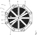
- a granulating device 1 for a screw machine comprises a strand generating device 2 and a knife carrier 3 with a plurality of cutting blades 4 arranged thereon.
- the knife carrier 3 with the Cutting knives 4 is arranged in a flow direction 5 of a material 6 to be granulated on a downstream side 7 of the strand generating device 2.
- the knife carrier 3 with the cutting blades 4 is rotatably drivable in the usual manner about a central longitudinal axis 8 by means of an electric drive motor, not shown.
- the knife carrier 3 with the cutting blades 4 can be displaced in the usual way in the direction of the central longitudinal axis 8, so that the cutting blades 4 can be arranged in abutment against the strand generating device 2 for operation of the granulating device 1.
- the strand generating device 2 serves to produce granular material strands 9 of the material 6 by flowing from an upstream side 10 through the strand generating device 2 to the downstream side 7.
- the strand generating device 2 has a plurality of perforated plates 11, which are arranged on a reinforcing support 12.
- the perforated plates 11 have a respective base plate 13 in which a plurality of through holes 14 are formed extending from the upstream side 10 to the downstream side 7.
- the passage holes 14 form a respective flow channel for the material 6, which has a conical inlet section and a subsequent cylindrical flow section.
- the reinforcing beam 12 comprises a plurality of reinforcing struts 15, which extend radially to the central longitudinal axis 8.
- the reinforcing struts 15 are arranged in a star shape and have equal angular distances from each other.
- the reinforcing struts 15 are integrally connected to each other at one of the central longitudinal axis 8 facing inner end 16.
- the reinforcing struts 15 are integrally via connecting struts 18 connected with each other.
- the connecting struts 18 are formed on a side facing the central longitudinal axis 8 as a circular arc.
- Neighboring reinforcing struts 15 define in pairs a respective associated free passage area 19.
- the free passage areas 19 are designed tapering in the direction of the central longitudinal axis 8. Due to the circular arc-shaped design of the connecting struts 18, the passage areas 19 have the shape of a circular sector.
- the perforated plates 11 are shaped according to the free passage areas 19.
- the perforated plates 11 are inserted from the downstream side 7 into recesses 20 of the reinforcing carrier 12, so that the perforated plates 11 with the reinforcing carrier 12 and the reinforcing struts 15 form a flat surface.
- the perforated plates 11 abut against a reinforcing carrier stop of the reinforcing carrier 12 in an edge region and are fastened interchangeably to the reinforcing carrier 12.
- the reinforcing struts 15 have a tapering in the direction of the upstream side 10 cross-section.
- the reinforcing struts 15 are preferably wedge-shaped.
- a number N of the reinforcing struts 15 is equal to a number M of the perforated plates 11.
- an integrally formed perforated plate 11 is disposed between each two adjacent reinforcing struts 15.
- the passage holes 14 of the respective perforated plate 11 are formed essentially in the entire associated passage area 19.
- N 8.
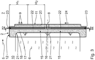
- the perforated plates 11 have a thickness D 1 in the region of the through-holes 14 in the flow direction 5. Furthermore, the reinforcement struts 15 have a thickness D 2 outside of a connection region 21 to the connection struts 18 in the flow direction 5.
- D 1 / D 2 is generally: 0.05 ⁇ D 1 / D 2 ⁇ 0.5, in particular 0.1 ⁇ D 1 / D 2 ⁇ 0.4, and in particular 0.15 ⁇ D 1 / D 2 ⁇ 0.3.
- the strand generating device 2 For heating the perforated plates 11, the strand generating device 2 has electric heating cartridges 22.
- the heating cartridges 22 are arranged in a respectively associated receiving space 23.
- the receiving spaces 23 are formed in the reinforcing carrier 12.
- a number K of the heating cartridges 22 corresponds to the number N of the reinforcing struts 15.
- each reinforcing strut 15 is thus formed a receiving space 23 which extends in a respective longitudinal direction 24 of the associated reinforcing strut 15, that extends radially.
- the associated heating cartridge 22 is arranged, which also extends in the longitudinal direction 24, ie radially.
- the heating cartridges 22 each have a heating power, which varies in the longitudinal direction of extension 24, ie in the direction of the central longitudinal axis 8, in particular decreases.
- the respective heating cartridge 22 for example, a heating circuit or more heating circuits with a variable and in particular adjustable heating power.
- the heating cartridges 22 form two heating areas H 1 and H 2 with different heating powers.
- the heating power in the heating area H 2 is smaller than the heating power in the heating area H 1 in the present embodiment.
- the Heating range H 1 has, for example, a heating power of 260 W, whereas heating range H 2 has a heating power of 130 W.
- each heating cartridge 22 thus has, for example, a heating power of 390 W, so that the perforated plates 11 can be heated with a total heating power of 3,120 W.
- the heating area H 1 and H 2 have a total length of, for example, 180 mm.
- the flowing material 6 is provided by a screw machine, which is arranged upstream of the granulating device 1.
- the material 6 flows from the upstream side 10 through the through holes 14 of the perforated plates 11, so that the material strands 9 are formed on the downstream side 7 of the perforated plates 11. This is in Fig. 3 indicated.
- the perforated plates 11 are heated by means of the heating cartridges 22.
- the heat generated by the heating cartridges 22 is distributed over the reinforcing struts 15 on the perforated plates 11 and transmitted.
- the perforated plates 11 are heated comparatively uniformly, since the mass to be heated of the perforated plates 11 decreases due to their shape in the direction of the central longitudinal axis 8. Furthermore, the material 6 on the upstream side 10 is additionally heated by the reinforcing member 12.
- the perforated plates 11 Due to the arrangement of the perforated plates 11 on the reinforcing member 12, the perforated plates 11 are formed with a small thickness D 1 , without their mechanical strength or rigidity is impaired. hereby the perforated plates 11 have a low flow resistance for the material 6, so that the pressure loss of the material 6 when flowing through the strand generating device 2 is low. In addition, the flow resistance of the reinforcing struts 15 is reduced by the wedge-shaped cross section, so that the reinforcing carrier 12 also causes a comparatively low pressure loss of the material 6.
- the material strands 9 produced are cut in a conventional manner by means of the rotating cutting blades 4, so that granules 9 are produced on the downstream side 7 from the material strands.
- the granulating device 1 or the strand generating device 2 thus enables in a simple manner a uniform heating of the perforated plates 11 in conjunction with a low pressure loss of the material 6 flowing through the perforated plates 11.
- a single orifice plate 11 may be disposed on the reinforcement beam 12 and form a flat surface for the at least one cutting blade 4.
- the perforated plate 11 or the perforated plates 11 and the reinforcing carrier 12 may be integrally formed.
Landscapes
- Engineering & Computer Science (AREA)
- Mechanical Engineering (AREA)
- Physics & Mathematics (AREA)
- Thermal Sciences (AREA)
- Manufacturing & Machinery (AREA)
- Chemical & Material Sciences (AREA)
- Organic Chemistry (AREA)
- Chemical Kinetics & Catalysis (AREA)
- Processing And Handling Of Plastics And Other Materials For Molding In General (AREA)
Claims (12)
- Dispositif de production de tiges pour produire des tiges de matériaux granulables, comprenant- au moins une platine perforée (11), présentant une plaque de base (13) et des trous de passage (14) s'étendant dans la plaque de base (13) d'un côté en amont (10) à un côté en aval (7),- au moins une cartouche chauffante électrique (22) pour chauffer l'au moins une plaque perforée (11),l'au moins une plaque perforée (11) étant disposée sur un support de renfort (12),
le support de renfort (12) comprenant une pluralité d'entretoises de renfort (15) pour supporter l'au moins une plaque perforée (11) en connexion avec une vaste répartition et transmission de la chaleur produite par l'au moins une cartouche chauffante électrique (22) sur l'au moins une plaque perforée (11), et
au moins un espace de logement (23) étant configuré dans l'au moins un support de renfort (12),
caractérisé en ce
que l'au moins un espace de logement (23) est configuré dans une entretoise de renfort (15) associée et s'étend dans une direction longitudinale d'extension (24) de l'entretoise de renfort (15),
que dans l'au moins un espace de logement (23), l'au moins une cartouche chauffante électrique (22) est disposée. - Dispositif de production de tiges selon la revendication 1, caractérisé en ce
que les entretoises de renfort (15) s'étendent radialement à l'axe central longitudinal (8). - Dispositif de production de tiges selon la revendication 1 ou 2, caractérisé en ce
que les entretoises de renfort (15) sont liées l'une à l'autre sur une extrémité intérieure respective (16) et/ou sur une extrémité extérieure respective (17). - Dispositif de production de tiges selon l'une quelconque des revendications 1 à 3, caractérisé en ce
qu'un nombre N des entretoises de renfort (15) est tel que: 2 ≤ N ≤ 16, en particulier 3 ≤ N ≤ 12, et en particulier 4 ≤ N ≤ 8. - Dispositif de production de tiges selon l'une quelconque des revendications 1 à 4, caractérisé en ce
que l'au moins une plaque perforée (11) est intégrée dans le support de renfort (12). - Dispositif de production de tiges selon l'une quelconque des revendications 1 à 5, caractérisé en ce
que le support de renfort (12), en particulier les entretoises de renfort (15), présentent au moins par passages une section transversale s'effilant en direction du côté en amont (10), celle-ci étant en particulier cunéiforme. - Dispositif de production de tiges selon l'une quelconque des revendications 1 à 6, caractérisé en ce
que l'au moins plaque perforée (11) présente une épaisseur D1 et les entretoises de renfort (15) présentent une épaisseur D2, telles que: 0,05 ≤ D1/D2 ≤ 0,5, en particulier 0,1 ≤ D1/D2 ≤ 0,4, et en particulier 0,15 ≤ D1/D2 ≤ 0,3. - Dispositif de production de tiges selon l'une quelconque des revendications 1 à 7, caractérisé en ce
que l'au moins une cartouche chauffante électrique (22) s'étend radialement à un axe central longitudinal (8) du support de renfort (12). - Dispositif de production de tiges selon la revendication 8, caractérisé en ce
que l'au moins une cartouche chauffante électrique (22) a une puissance de chauffage variant, en particulier diminuant, en direction the l'axe central longitudinal (8). - Dispositif de production de tiges selon l'une quelconque des revendications 1 à 9, caractérisé en ce
qu'une pluralité de plaques perforées (11) est disposée sur le support de renfort (12), en particulier un nombre M des plaques perforées (11) étant égal à un nombre N des entretoises de renfort (15). - Dispositif de production de tiges selon l'une quelconque des revendications 1 à 10, caractérisé en ce
que dans chaque entretoise de renfort (15), un espace de logement (23) est configuré et une cartouche chauffante électrique (22) associée est disposée dedans. - Dispositif de granulation pour une machine à vis, comprenant- un dispositif de production de tiges (2) selon l'une quelconque des revendications 1 à 11, et- au moins une lame (4) entraînable en rotation, disposée sur le côté en aval (7) du dispositif de production de tiges (2).
Priority Applications (1)
| Application Number | Priority Date | Filing Date | Title |
|---|---|---|---|
| EP16152944.1A EP3199314B1 (fr) | 2016-01-27 | 2016-01-27 | Dispositif de production de tiges, et dispositif de granulation associé |
Applications Claiming Priority (1)
| Application Number | Priority Date | Filing Date | Title |
|---|---|---|---|
| EP16152944.1A EP3199314B1 (fr) | 2016-01-27 | 2016-01-27 | Dispositif de production de tiges, et dispositif de granulation associé |
Publications (2)
| Publication Number | Publication Date |
|---|---|
| EP3199314A1 EP3199314A1 (fr) | 2017-08-02 |
| EP3199314B1 true EP3199314B1 (fr) | 2019-07-31 |
Family
ID=55272255
Family Applications (1)
| Application Number | Title | Priority Date | Filing Date |
|---|---|---|---|
| EP16152944.1A Active EP3199314B1 (fr) | 2016-01-27 | 2016-01-27 | Dispositif de production de tiges, et dispositif de granulation associé |
Country Status (1)
| Country | Link |
|---|---|
| EP (1) | EP3199314B1 (fr) |
Family Cites Families (12)
| Publication number | Priority date | Publication date | Assignee | Title |
|---|---|---|---|---|
| DD113322B1 (de) | 1974-03-19 | 1987-04-08 | Karl Marx Stadt Maschf | Lochplatte fuer doppelschneckenextruder |
| US4421470A (en) * | 1982-03-04 | 1983-12-20 | Kensaku Nakamura | Resin pellet producing machine |
| US4621996A (en) * | 1985-04-24 | 1986-11-11 | Gala Industries, Inc. | Removable die center for extrusion dies |
| WO2004080678A1 (fr) * | 2003-03-12 | 2004-09-23 | Sekisui Plastics Co., Ltd. | Patrice de granulation, dispositif de granulation, et procede de fabrication d'une granule de resine thermoplastique expansible |
| DE10322610A1 (de) | 2003-05-20 | 2004-12-09 | Coperion Werner & Pfleiderer Gmbh & Co.Kg | Granulier-Vorrichtung |
| WO2008102874A1 (fr) * | 2007-02-23 | 2008-08-28 | Sekisui Plastics Co., Ltd. | Matrice de granulation, appareil de granulation et procédé de fabrication d'un grain de résine thermoplastique extensible |
| DE102008004858A1 (de) * | 2008-01-17 | 2009-07-23 | C. F. Scheer & Cie Gmbh & Co | Temperieren der Düsenplatte eines Unterwassergranulators |
| JP5086900B2 (ja) * | 2008-06-04 | 2012-11-28 | 積水化成品工業株式会社 | 発泡性熱可塑性樹脂粒子の製造方法、熱可塑性樹脂発泡粒子の製造方法及び熱可塑性樹脂発泡成形体の製造方法 |
| US20100040716A1 (en) * | 2008-08-13 | 2010-02-18 | Fridley Michael A | Thermally insulated die plate assembly for underwater pelletizing and the like |
| JP2010179627A (ja) * | 2009-02-09 | 2010-08-19 | Sekisui Plastics Co Ltd | 発泡性熱可塑性樹脂粒子の製造方法、熱可塑性樹脂発泡粒子の製造方法及び熱可塑性樹脂発泡成形体の製造方法 |
| DE102010030614B4 (de) * | 2010-06-28 | 2014-02-20 | Reduction Engineering Gmbh | Lochplatte für einen Unterwassergranulator |
| DE102013200661B4 (de) * | 2013-01-17 | 2016-04-07 | Reduction Engineering Gmbh | Düse und lochplatte für einen unterwassergranulator |
-
2016
- 2016-01-27 EP EP16152944.1A patent/EP3199314B1/fr active Active
Non-Patent Citations (1)
| Title |
|---|
| None * |
Also Published As
| Publication number | Publication date |
|---|---|
| EP3199314A1 (fr) | 2017-08-02 |
Similar Documents
| Publication | Publication Date | Title |
|---|---|---|
| DE69737118T2 (de) | Doppelschneckenkneter | |
| EP1749564B1 (fr) | Stabilisateur pour mélanger ou bien stabiliser un mélange dans un champ de cavitation hydrodynamique | |
| DE60312881T2 (de) | Modular aufgebaute wasserstromführung für unterwassergranulierer | |
| DE112016001990B4 (de) | Extruderschnecke, Extruder und Extrusionsverfahren | |
| DE10103094B4 (de) | Zwillingsschneckenextruder | |
| EP2134521B1 (fr) | Dispositif pour produire des granulés à partir d'un plastique en fusion | |
| EP3511139B1 (fr) | Dispositif de buse pour dispositif de granulation, dispositif de granulation, et procédé associé | |
| DE2839552B2 (de) | Düsenkopf zum Herstellen von Kunststoffgranulat | |
| DE2557166A1 (de) | Granulator | |
| CH434700A (de) | Granuliervorrichtung, insbesondere für thermoplastische Kunststoffe und Verfahren zu ihrem Betrieb | |
| EP2921279B1 (fr) | Dispositif et procédé d'homogénéisation de coulées de matière synthétique | |
| EP4017693B1 (fr) | Système de granulation sous l'eau, et procédé s'y rapportant pour la granulation d'une masse fondue de polymère | |
| EP2001650B1 (fr) | Element helicoidal | |
| DE3873619T2 (de) | Extruderduese. | |
| EP3199314B1 (fr) | Dispositif de production de tiges, et dispositif de granulation associé | |
| DE102012025259B4 (de) | Blockträger mit integrierter Stranggießeinrichtung für thermoplastische Kunststoffe sowie Granuliervorrichtung | |
| EP1121238B1 (fr) | Extrudeuse a deux vis a rotation identique | |
| EP3439847B1 (fr) | Vis sans fin à thermorégulation interne, installation et procédé de mise en oeuvre d'une telle vis sans fin | |
| EP2501531B1 (fr) | Appareil pour granuler | |
| DD233270A3 (de) | Mischelement fuer plastizier- und/oder foerderschnecken | |
| DE102009032993A1 (de) | Vorrichtung und Verfahren zum Granulieren von Kunststoffmaterial | |
| DE112021007649T5 (de) | Granulator, Mechanismus zum Einstellen des Knetens und Verfahren zum Herstellen von Harzpellets | |
| DE3420944A1 (de) | Granulierwerkzeug fuer einen kunstharzextruder | |
| AT523083B1 (de) | Unterwassergranulator | |
| EP1955837B1 (fr) | Dispositif et procédé destinés à répartir une masse en matière plastique |
Legal Events
| Date | Code | Title | Description |
|---|---|---|---|
| PUAI | Public reference made under article 153(3) epc to a published international application that has entered the european phase |
Free format text: ORIGINAL CODE: 0009012 |
|
| STAA | Information on the status of an ep patent application or granted ep patent |
Free format text: STATUS: THE APPLICATION HAS BEEN PUBLISHED |
|
| AK | Designated contracting states |
Kind code of ref document: A1 Designated state(s): AL AT BE BG CH CY CZ DE DK EE ES FI FR GB GR HR HU IE IS IT LI LT LU LV MC MK MT NL NO PL PT RO RS SE SI SK SM TR |
|
| AX | Request for extension of the european patent |
Extension state: BA ME |
|
| STAA | Information on the status of an ep patent application or granted ep patent |
Free format text: STATUS: REQUEST FOR EXAMINATION WAS MADE |
|
| 17P | Request for examination filed |
Effective date: 20180131 |
|
| RBV | Designated contracting states (corrected) |
Designated state(s): AL AT BE BG CH CY CZ DE DK EE ES FI FR GB GR HR HU IE IS IT LI LT LU LV MC MK MT NL NO PL PT RO RS SE SI SK SM TR |
|
| STAA | Information on the status of an ep patent application or granted ep patent |
Free format text: STATUS: EXAMINATION IS IN PROGRESS |
|
| 17Q | First examination report despatched |
Effective date: 20180530 |
|
| GRAP | Despatch of communication of intention to grant a patent |
Free format text: ORIGINAL CODE: EPIDOSNIGR1 |
|
| STAA | Information on the status of an ep patent application or granted ep patent |
Free format text: STATUS: GRANT OF PATENT IS INTENDED |
|
| RIC1 | Information provided on ipc code assigned before grant |
Ipc: B29C 48/345 20190101ALI20190204BHEP Ipc: B29C 48/86 20190101ALI20190204BHEP Ipc: B01J 2/20 20060101ALI20190204BHEP Ipc: B29C 48/30 20190101ALI20190204BHEP Ipc: B29C 48/04 20190101ALN20190204BHEP Ipc: B29B 9/06 20060101AFI20190204BHEP Ipc: B29C 48/05 20190101ALN20190204BHEP |
|
| INTG | Intention to grant announced |
Effective date: 20190220 |
|
| GRAS | Grant fee paid |
Free format text: ORIGINAL CODE: EPIDOSNIGR3 |
|
| GRAA | (expected) grant |
Free format text: ORIGINAL CODE: 0009210 |
|
| STAA | Information on the status of an ep patent application or granted ep patent |
Free format text: STATUS: THE PATENT HAS BEEN GRANTED |
|
| AK | Designated contracting states |
Kind code of ref document: B1 Designated state(s): AL AT BE BG CH CY CZ DE DK EE ES FI FR GB GR HR HU IE IS IT LI LT LU LV MC MK MT NL NO PL PT RO RS SE SI SK SM TR |
|
| REG | Reference to a national code |
Ref country code: CH Ref legal event code: EP Ref country code: GB Ref legal event code: FG4D Free format text: NOT ENGLISH |
|
| REG | Reference to a national code |
Ref country code: DE Ref legal event code: R096 Ref document number: 502016005755 Country of ref document: DE |
|
| REG | Reference to a national code |
Ref country code: AT Ref legal event code: REF Ref document number: 1160438 Country of ref document: AT Kind code of ref document: T Effective date: 20190815 |
|
| REG | Reference to a national code |
Ref country code: IE Ref legal event code: FG4D Free format text: LANGUAGE OF EP DOCUMENT: GERMAN |
|
| REG | Reference to a national code |
Ref country code: NL Ref legal event code: MP Effective date: 20190731 |
|
| REG | Reference to a national code |
Ref country code: LT Ref legal event code: MG4D |
|
| PG25 | Lapsed in a contracting state [announced via postgrant information from national office to epo] |
Ref country code: HR Free format text: LAPSE BECAUSE OF FAILURE TO SUBMIT A TRANSLATION OF THE DESCRIPTION OR TO PAY THE FEE WITHIN THE PRESCRIBED TIME-LIMIT Effective date: 20190731 Ref country code: NO Free format text: LAPSE BECAUSE OF FAILURE TO SUBMIT A TRANSLATION OF THE DESCRIPTION OR TO PAY THE FEE WITHIN THE PRESCRIBED TIME-LIMIT Effective date: 20191031 Ref country code: SE Free format text: LAPSE BECAUSE OF FAILURE TO SUBMIT A TRANSLATION OF THE DESCRIPTION OR TO PAY THE FEE WITHIN THE PRESCRIBED TIME-LIMIT Effective date: 20190731 Ref country code: FI Free format text: LAPSE BECAUSE OF FAILURE TO SUBMIT A TRANSLATION OF THE DESCRIPTION OR TO PAY THE FEE WITHIN THE PRESCRIBED TIME-LIMIT Effective date: 20190731 Ref country code: PT Free format text: LAPSE BECAUSE OF FAILURE TO SUBMIT A TRANSLATION OF THE DESCRIPTION OR TO PAY THE FEE WITHIN THE PRESCRIBED TIME-LIMIT Effective date: 20191202 Ref country code: LT Free format text: LAPSE BECAUSE OF FAILURE TO SUBMIT A TRANSLATION OF THE DESCRIPTION OR TO PAY THE FEE WITHIN THE PRESCRIBED TIME-LIMIT Effective date: 20190731 Ref country code: NL Free format text: LAPSE BECAUSE OF FAILURE TO SUBMIT A TRANSLATION OF THE DESCRIPTION OR TO PAY THE FEE WITHIN THE PRESCRIBED TIME-LIMIT Effective date: 20190731 Ref country code: BG Free format text: LAPSE BECAUSE OF FAILURE TO SUBMIT A TRANSLATION OF THE DESCRIPTION OR TO PAY THE FEE WITHIN THE PRESCRIBED TIME-LIMIT Effective date: 20191031 |
|
| PG25 | Lapsed in a contracting state [announced via postgrant information from national office to epo] |
Ref country code: ES Free format text: LAPSE BECAUSE OF FAILURE TO SUBMIT A TRANSLATION OF THE DESCRIPTION OR TO PAY THE FEE WITHIN THE PRESCRIBED TIME-LIMIT Effective date: 20190731 Ref country code: LV Free format text: LAPSE BECAUSE OF FAILURE TO SUBMIT A TRANSLATION OF THE DESCRIPTION OR TO PAY THE FEE WITHIN THE PRESCRIBED TIME-LIMIT Effective date: 20190731 Ref country code: AL Free format text: LAPSE BECAUSE OF FAILURE TO SUBMIT A TRANSLATION OF THE DESCRIPTION OR TO PAY THE FEE WITHIN THE PRESCRIBED TIME-LIMIT Effective date: 20190731 Ref country code: GR Free format text: LAPSE BECAUSE OF FAILURE TO SUBMIT A TRANSLATION OF THE DESCRIPTION OR TO PAY THE FEE WITHIN THE PRESCRIBED TIME-LIMIT Effective date: 20191101 Ref country code: IS Free format text: LAPSE BECAUSE OF FAILURE TO SUBMIT A TRANSLATION OF THE DESCRIPTION OR TO PAY THE FEE WITHIN THE PRESCRIBED TIME-LIMIT Effective date: 20191130 Ref country code: RS Free format text: LAPSE BECAUSE OF FAILURE TO SUBMIT A TRANSLATION OF THE DESCRIPTION OR TO PAY THE FEE WITHIN THE PRESCRIBED TIME-LIMIT Effective date: 20190731 |
|
| PG25 | Lapsed in a contracting state [announced via postgrant information from national office to epo] |
Ref country code: TR Free format text: LAPSE BECAUSE OF FAILURE TO SUBMIT A TRANSLATION OF THE DESCRIPTION OR TO PAY THE FEE WITHIN THE PRESCRIBED TIME-LIMIT Effective date: 20190731 |
|
| PG25 | Lapsed in a contracting state [announced via postgrant information from national office to epo] |
Ref country code: RO Free format text: LAPSE BECAUSE OF FAILURE TO SUBMIT A TRANSLATION OF THE DESCRIPTION OR TO PAY THE FEE WITHIN THE PRESCRIBED TIME-LIMIT Effective date: 20190731 Ref country code: PL Free format text: LAPSE BECAUSE OF FAILURE TO SUBMIT A TRANSLATION OF THE DESCRIPTION OR TO PAY THE FEE WITHIN THE PRESCRIBED TIME-LIMIT Effective date: 20190731 Ref country code: EE Free format text: LAPSE BECAUSE OF FAILURE TO SUBMIT A TRANSLATION OF THE DESCRIPTION OR TO PAY THE FEE WITHIN THE PRESCRIBED TIME-LIMIT Effective date: 20190731 Ref country code: DK Free format text: LAPSE BECAUSE OF FAILURE TO SUBMIT A TRANSLATION OF THE DESCRIPTION OR TO PAY THE FEE WITHIN THE PRESCRIBED TIME-LIMIT Effective date: 20190731 |
|
| PG25 | Lapsed in a contracting state [announced via postgrant information from national office to epo] |
Ref country code: SM Free format text: LAPSE BECAUSE OF FAILURE TO SUBMIT A TRANSLATION OF THE DESCRIPTION OR TO PAY THE FEE WITHIN THE PRESCRIBED TIME-LIMIT Effective date: 20190731 Ref country code: SK Free format text: LAPSE BECAUSE OF FAILURE TO SUBMIT A TRANSLATION OF THE DESCRIPTION OR TO PAY THE FEE WITHIN THE PRESCRIBED TIME-LIMIT Effective date: 20190731 Ref country code: CZ Free format text: LAPSE BECAUSE OF FAILURE TO SUBMIT A TRANSLATION OF THE DESCRIPTION OR TO PAY THE FEE WITHIN THE PRESCRIBED TIME-LIMIT Effective date: 20190731 Ref country code: IS Free format text: LAPSE BECAUSE OF FAILURE TO SUBMIT A TRANSLATION OF THE DESCRIPTION OR TO PAY THE FEE WITHIN THE PRESCRIBED TIME-LIMIT Effective date: 20200224 |
|
| REG | Reference to a national code |
Ref country code: DE Ref legal event code: R097 Ref document number: 502016005755 Country of ref document: DE |
|
| PLBE | No opposition filed within time limit |
Free format text: ORIGINAL CODE: 0009261 |
|
| STAA | Information on the status of an ep patent application or granted ep patent |
Free format text: STATUS: NO OPPOSITION FILED WITHIN TIME LIMIT |
|
| PG2D | Information on lapse in contracting state deleted |
Ref country code: IS |
|
| PG25 | Lapsed in a contracting state [announced via postgrant information from national office to epo] |
Ref country code: IS Free format text: LAPSE BECAUSE OF FAILURE TO SUBMIT A TRANSLATION OF THE DESCRIPTION OR TO PAY THE FEE WITHIN THE PRESCRIBED TIME-LIMIT Effective date: 20191030 |
|
| 26N | No opposition filed |
Effective date: 20200603 |
|
| PG25 | Lapsed in a contracting state [announced via postgrant information from national office to epo] |
Ref country code: MC Free format text: LAPSE BECAUSE OF FAILURE TO SUBMIT A TRANSLATION OF THE DESCRIPTION OR TO PAY THE FEE WITHIN THE PRESCRIBED TIME-LIMIT Effective date: 20190731 Ref country code: SI Free format text: LAPSE BECAUSE OF FAILURE TO SUBMIT A TRANSLATION OF THE DESCRIPTION OR TO PAY THE FEE WITHIN THE PRESCRIBED TIME-LIMIT Effective date: 20190731 |
|
| REG | Reference to a national code |
Ref country code: CH Ref legal event code: PL |
|
| GBPC | Gb: european patent ceased through non-payment of renewal fee |
Effective date: 20200127 |
|
| REG | Reference to a national code |
Ref country code: BE Ref legal event code: MM Effective date: 20200131 |
|
| PG25 | Lapsed in a contracting state [announced via postgrant information from national office to epo] |
Ref country code: FR Free format text: LAPSE BECAUSE OF NON-PAYMENT OF DUE FEES Effective date: 20200131 Ref country code: GB Free format text: LAPSE BECAUSE OF NON-PAYMENT OF DUE FEES Effective date: 20200127 Ref country code: LU Free format text: LAPSE BECAUSE OF NON-PAYMENT OF DUE FEES Effective date: 20200127 |
|
| PG25 | Lapsed in a contracting state [announced via postgrant information from national office to epo] |
Ref country code: LI Free format text: LAPSE BECAUSE OF NON-PAYMENT OF DUE FEES Effective date: 20200131 Ref country code: BE Free format text: LAPSE BECAUSE OF NON-PAYMENT OF DUE FEES Effective date: 20200131 Ref country code: CH Free format text: LAPSE BECAUSE OF NON-PAYMENT OF DUE FEES Effective date: 20200131 |
|
| PG25 | Lapsed in a contracting state [announced via postgrant information from national office to epo] |
Ref country code: IE Free format text: LAPSE BECAUSE OF NON-PAYMENT OF DUE FEES Effective date: 20200127 |
|
| REG | Reference to a national code |
Ref country code: AT Ref legal event code: MM01 Ref document number: 1160438 Country of ref document: AT Kind code of ref document: T Effective date: 20210127 |
|
| PG25 | Lapsed in a contracting state [announced via postgrant information from national office to epo] |
Ref country code: AT Free format text: LAPSE BECAUSE OF NON-PAYMENT OF DUE FEES Effective date: 20210127 |
|
| PG25 | Lapsed in a contracting state [announced via postgrant information from national office to epo] |
Ref country code: MT Free format text: LAPSE BECAUSE OF FAILURE TO SUBMIT A TRANSLATION OF THE DESCRIPTION OR TO PAY THE FEE WITHIN THE PRESCRIBED TIME-LIMIT Effective date: 20190731 Ref country code: CY Free format text: LAPSE BECAUSE OF FAILURE TO SUBMIT A TRANSLATION OF THE DESCRIPTION OR TO PAY THE FEE WITHIN THE PRESCRIBED TIME-LIMIT Effective date: 20190731 |
|
| PG25 | Lapsed in a contracting state [announced via postgrant information from national office to epo] |
Ref country code: MK Free format text: LAPSE BECAUSE OF FAILURE TO SUBMIT A TRANSLATION OF THE DESCRIPTION OR TO PAY THE FEE WITHIN THE PRESCRIBED TIME-LIMIT Effective date: 20190731 |
|
| PGFP | Annual fee paid to national office [announced via postgrant information from national office to epo] |
Ref country code: DE Payment date: 20260120 Year of fee payment: 11 |
|
| PGFP | Annual fee paid to national office [announced via postgrant information from national office to epo] |
Ref country code: IT Payment date: 20260130 Year of fee payment: 11 |