EP3199424B1 - Lenksäulenvorrichtung - Google Patents
Lenksäulenvorrichtung Download PDFInfo
- Publication number
- EP3199424B1 EP3199424B1 EP15858026.6A EP15858026A EP3199424B1 EP 3199424 B1 EP3199424 B1 EP 3199424B1 EP 15858026 A EP15858026 A EP 15858026A EP 3199424 B1 EP3199424 B1 EP 3199424B1
- Authority
- EP
- European Patent Office
- Prior art keywords
- vehicle body
- steering column
- sleeve
- lock member
- sliding plate
- Prior art date
- Legal status (The legal status is an assumption and is not a legal conclusion. Google has not performed a legal analysis and makes no representation as to the accuracy of the status listed.)
- Active
Links
- 239000002775 capsule Substances 0.000 claims description 37
- 229920003002 synthetic resin Polymers 0.000 claims description 13
- 239000000057 synthetic resin Substances 0.000 claims description 13
- 230000002265 prevention Effects 0.000 claims description 4
- 210000000078 claw Anatomy 0.000 description 7
- 239000000463 material Substances 0.000 description 5
- 230000035939 shock Effects 0.000 description 5
- 238000000034 method Methods 0.000 description 4
- 238000005452 bending Methods 0.000 description 3
- 238000010521 absorption reaction Methods 0.000 description 2
- 239000002783 friction material Substances 0.000 description 2
- 239000000314 lubricant Substances 0.000 description 2
- XEEYBQQBJWHFJM-UHFFFAOYSA-N Iron Chemical compound [Fe] XEEYBQQBJWHFJM-UHFFFAOYSA-N 0.000 description 1
- 229910001209 Low-carbon steel Inorganic materials 0.000 description 1
- FYYHWMGAXLPEAU-UHFFFAOYSA-N Magnesium Chemical compound [Mg] FYYHWMGAXLPEAU-UHFFFAOYSA-N 0.000 description 1
- 239000000853 adhesive Substances 0.000 description 1
- 230000001070 adhesive effect Effects 0.000 description 1
- 229910052782 aluminium Inorganic materials 0.000 description 1
- XAGFODPZIPBFFR-UHFFFAOYSA-N aluminium Chemical compound [Al] XAGFODPZIPBFFR-UHFFFAOYSA-N 0.000 description 1
- 239000004020 conductor Substances 0.000 description 1
- 230000001419 dependent effect Effects 0.000 description 1
- 230000000694 effects Effects 0.000 description 1
- 229910052749 magnesium Inorganic materials 0.000 description 1
- 239000011777 magnesium Substances 0.000 description 1
- 201000002266 mite infestation Diseases 0.000 description 1
- 239000007787 solid Substances 0.000 description 1
- 230000002123 temporal effect Effects 0.000 description 1
Images



Classifications
-
- B—PERFORMING OPERATIONS; TRANSPORTING
- B62—LAND VEHICLES FOR TRAVELLING OTHERWISE THAN ON RAILS
- B62D—MOTOR VEHICLES; TRAILERS
- B62D1/00—Steering controls, i.e. means for initiating a change of direction of the vehicle
- B62D1/02—Steering controls, i.e. means for initiating a change of direction of the vehicle vehicle-mounted
- B62D1/16—Steering columns
- B62D1/18—Steering columns yieldable or adjustable, e.g. tiltable
- B62D1/19—Steering columns yieldable or adjustable, e.g. tiltable incorporating energy-absorbing arrangements, e.g. by being yieldable or collapsible
- B62D1/195—Yieldable supports for the steering column
-
- B—PERFORMING OPERATIONS; TRANSPORTING
- B62—LAND VEHICLES FOR TRAVELLING OTHERWISE THAN ON RAILS
- B62D—MOTOR VEHICLES; TRAILERS
- B62D1/00—Steering controls, i.e. means for initiating a change of direction of the vehicle
- B62D1/02—Steering controls, i.e. means for initiating a change of direction of the vehicle vehicle-mounted
- B62D1/16—Steering columns
- B62D1/18—Steering columns yieldable or adjustable, e.g. tiltable
- B62D1/184—Mechanisms for locking columns at selected positions
-
- B—PERFORMING OPERATIONS; TRANSPORTING
- B62—LAND VEHICLES FOR TRAVELLING OTHERWISE THAN ON RAILS
- B62D—MOTOR VEHICLES; TRAILERS
- B62D1/00—Steering controls, i.e. means for initiating a change of direction of the vehicle
- B62D1/02—Steering controls, i.e. means for initiating a change of direction of the vehicle vehicle-mounted
- B62D1/16—Steering columns
- B62D1/18—Steering columns yieldable or adjustable, e.g. tiltable
- B62D1/187—Steering columns yieldable or adjustable, e.g. tiltable with tilt adjustment; with tilt and axial adjustment
- B62D1/189—Steering columns yieldable or adjustable, e.g. tiltable with tilt adjustment; with tilt and axial adjustment the entire column being tiltable as a unit
Definitions
- the present invention relates to a steering column device, and in particular, to a steering column device in which a steering column is configured to release forward from a vehicle body upon a secondary collision, together with a steering shaft.
- a steering column device in which a steering column is configured to release from a vehicle body together with a steering shaft has been suggested.
- a structure where a vehicle body mounting bracket integrated with the steering column is fixed to the vehicle body via a so-called capsule and the vehicle body mounting bracket is to be released by a shock load upon the secondary collision has been adopted.
- Patent Document 1 discloses a structure where a vehicle body mounting bracket is formed with a substantially U-shaped notch groove opening rearward of a vehicle body and having a narrow width of the opening end portion, a bush (6) configuring a capsule is fitted to an inner surface of the notch groove, and the bush (6) is sandwiched by a collar (7) and a ring (8) and is mounted to the vehicle body mounting bracket, which is then fixed to the vehicle body and is to release from the vehicle body by a predetermined load.
- the capsule of the steering column device disclosed in Patent Document 1 is applied with a frictional force, which is to be caused when the vehicle body mounting bracket is sandwiched by the collar (7) and the ring (8), in addition to a release load with which the bush (6) is to release from the notch groove of the vehicle body mounting bracket. Therefore, in order to reduce the release load, it is necessary to strictly mange dimensional precision of the bush. Also, like the capsule of the steering column device disclosed in Patent Document 2 and Patent Document 3, according to the configuration where the washer (7) coated with the synthetic resin of low friction or the sliding plate is used, when the release load from the vehicle body is reduced, the fixing to the vehicle body becomes unstable. Therefore, it is necessary to strictly limit an allowable range of tightening torque of a bolt.
- EP 1 336 546 A1 discloses an adjustment device mounted in a support unit fixed to the vehicle structure by fixings.
- Each fixing comprises two energy absorption caps which are arranged and clamped in the support unit by assembly means.
- These assembly means comprises a retaining rod with a shoulder at one end and a threaded part at its other end which receives a nut in order to clamp the required value to the energy absorption caps on the support unit. The adjustment of the clamping of the assembly is thus independent of the value of the clamping of the fixing of the support unit on the vehicle structure.
- a steering column device of the present invention includes a steering shaft capable of mounting a steering wheel to a vehicle body rear side, a steering column configured to rotatably pivotally support the steering shaft, and a vehicle body mounting bracket having a flange part, which has a notch groove formed thereon and opening towards the vehicle body rear side, and integrally provided with the steering column, wherein the vehicle body mounting bracket is configured to support the steering column to the vehicle body by fixing of the flange part, to the vehicle body and to move towards a vehicle body front side and to release from the vehicle body together with the steering column upon a secondary collision.
- the sleeve has a male screw formed on a cylindrical part thereof and is configured to be screwed with a female screw formed at a round hole of the lock member, and the desired release load is adjusted by tightening torque of the lock member.
- the fixing part of the sleeve may be a clip plate configured to be fitted to a groove provided at the cylindrical part.
- the fixing part of the sleeve may be a flange provided at an end portion of the cylindrical part.
- the sliding plate may be coated with a synthetic resin film of low friction on a contact surface with the vehicle body mounting bracket.
- the sliding plate may be configured by an outer sliding plate of which an inner surface is coated with a synthetic resin film of low friction and an inner sliding plate of which an outer surface is coated with a synthetic resin film of low friction, and the synthetic resin films of low friction may be configured to face each other.
- the lock member may be provided with a protrusion provided at a tip end of the cylindrical part and have a loosening prevention mechanism configured to suppress rotation of the lock member.
- FIG. 1 is an overall side view of a steering column device of the present invention.
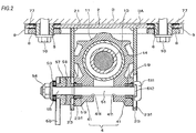
- FIG. 2 is a sectional view taken along a line A-A of FIG. 1 .
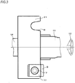
- FIG. 3 is a plan view depicting an upper-side vehicle body mounting bracket of FIG. 1 , in which one capsule is omitted.
- FIG. 4 is an exploded perspective view of a capsule of a first embodiment of the present invention.
- FIG. 5 is a sectional view of the capsule shown in FIG. 4 , depicting a state after a bolt is fastened.
- FIGS. 1 to 3 depict an embodiment where the present invention is applied to a tilt and telescopic steering column device.
- a steering shaft 13 having a steering wheel 12 mounted to a vehicle body rear side is rotatably pivotally supported to an inner diameter part of an outer column 11 by bearings 131, 131.
- the outer column 11 is externally fitted to an inner column 14 so as to be axially moveable.
- a lower-side vehicle body mounting bracket 15 is tiltably pivotally supported to a vehicle body 3 by a pivot pin 16.
- the outer column 11 and the inner column 14 configure the steering column of the present invention.
- a fastening rod 51 having a round rod shape is inserted from a right side of FIG. 2 through the long holes for tilt 231, 231 and the telescopic long holes 411, 411.
- a right end of the fastening rod 51 is formed with a cylindrical head part 511, and a right outer diameter part of the head part 511 is formed with a rotation stop part 512 having a rectangular section of which a width is slightly narrower than a groove width of the long hole for tilt 231.
- the rotation stop part 512 is fitted in the long hole for tilt 231, and is configured to stop rotation of the fastening rod 51 relative to the upper-side vehicle body mounting bracket 2 and to slide the fastening rod 51 along the long hole for tilt 231 upon adjustment of a tilt position.
- outer openings of the telescopic long holes 411, 411 in a vehicle width direction are mounted with sleeves 59, 59 having a long hole shape to which the fastening rod 51 is to be loosely fitted.
- the operating lever 56 Upon an unclamping, the operating lever 56 is rotated in an opposite direction, phases of both the cam threads of the moveable cam 57 and the stationary cam 58 are offset, so that bracing of the cam mechanism is released and the force of pulling leftward the fastening rod 51 is released. Thereby, the side plates 23, 23 are spaced from each other, so that the fastening of the right and left held parts 41, 41 of the distance bracket 4 and the force of the held parts 41, 41 fastening the inner column 14 are released.
- the flange part 21 is formed with notch grooves 6, 6 having a substantial U shape opening towards the vehicle body rear side (a right side in FIG. 3 ).
- the flange part 21 is detachably mounted to the vehicle body 3 by using the notch grooves 6, 6.
- FIGS. 4 to 6 depict a first embodiment of a method of mounting the flange part 21 of one side to the vehicle body 3.
- a method of mounting the flange part of the other side to the vehicle body 3 is the same as the method of mounting one flange part 21 to the vehicle body 3.
- FIGS. 4 and 5 depict in detail a capsule of the first embodiment.
- a release capsule configured to mount the flange part 21 to the vehicle body 3 is configured by a sleeve 7, a clip plate 77, which is an example of the fixing part, a lock member 8 and a sliding plate 9.
- the sleeve 7 is a column configured to insert the cylindrical part 72 in a part at which a round hole 93 of an outer sliding plate 91 of the sliding plate 9, a notch groove 94 of an inner sliding plate 92 and the notch groove 6 of the flange part 21 overlap each other, and to sandwich the sliding plate 9 and the flange part 21 by the clip plate 77 mounted to the groove 71 and the lock member 8 to be screwed to the cylindrical part 72.
- the through-hole 73 is configured as a socket for inserting therein a fastening tool and has a quadrangular shape, in the first embodiment.
- the through-hole 73 is not necessarily required to have the quadrangular shape and may have a well-known shape such as an oval shape, a hexagonal shape, an octagonal shape or the like.
- the clip plate 77 is formed of a thin conductive plate having a thickness of about 0.3mm to 0.8mm by bending the thin plate with a press.
- the clip plate 77 is inserted between an upper surface 21B of the flange part 21 and a lower surface 3A of the vehicle body 3.
- the clip plate 77 is formed at a center thereof with a through-hole 78.
- the through-hole 78 is formed with a plurality of claws 77A, which are arranged at equal intervals on a periphery thereof and formed radially towards the center of the clip plate 77.
- a diameter size of a circle inscribed in inner sides of the claws 77A is formed to be slightly smaller than an outer diameter size of a groove bottom of the groove 71 of the cylindrical part 72.
- the clip plate 77 when the clip plate 77 is pushed into the cylindrical part 72 of the sleeve 7, the clip plate is fitted to the groove 71 provided at the end portion of the cylindrical part 72 with the claws 77A being enlarged radially outwards, and the inner sides of the claws 77A are bitten to the outer periphery of the groove 71 by an elastic force of the claws 77A, so that the clip plate 77 and the sleeve 7 are coupled. That is, the claws 77A have a function of a push nut.
- the sliding plate 9 includes an outer sliding plate 91, which is formed by bending a thin conductive plate having a thickness of about 0.3mm to 0.8mm into a U-shape and has a coated surface 91A coated on an inner side thereof with a low friction material made of a synthetic resin film of low friction, and an inner sliding plate 92, which is formed by bending a thin conductive plate having a thickness of about 0.3mm to 0.8mm into a U-shape and has a coated surface 92A coated on an outer side thereof with the same low friction material.
- the inner sliding plate 92 is fitted to the outer sliding plate 91 so that the coated surface 91A and the coated surface 92A face each other.
- the outer sliding plate 91 is formed at its central part with a round hole 93 through which the sleeve 7 is to pass, and the inner sliding plate 92 is formed with a substantially U-shaped notch groove 94 of which one side is opened and through which the sleeve 7 is to pass.
- the notch groove 94 has the same shape as the notch groove 6 of the flange part 21.
- the lock member 8 is a circular lock nut, and a round hole 81 of an inner diameter part thereof is formed with a female screw and is screwed to the male screw of the cylindrical part 72 of the sleeve 7. Also, an outer diameter of the lock member 8 is formed with a concave part 82, and the fastening tool is mounted and screw-fastened thereto.
- the concave part 82 is not necessarily required to be a groove, and an outward shape thereof may be a well-known shape such as a hexahedral shape.
- an end surface of the lock member 8 is formed with a protrusion 84 protruding around the round hole 81.
- the protrusion 84 may not be provided.
- the sleeve 7 having the clip plate 77 mounted thereto passes through the round hole 93, the notch groove 94 and the notch groove 6, and the lock member 8 is screwed to the sleeve 7, so that the release capsule of the first embodiment is fixed to the flange 21.
- the fixing bolt 10 passes through the through-hole 73 and is fastened to the vehicle body 3, so that the steering column device is mounted to the vehicle body.
- the fastening member a well-known member such as a stud bolt and a nut can also be used, instead of the fixing bolt 10.
- the release capsule When a secondary collision occurs, the release capsule is released from the flange 21 due to a shock upon-the secondary collision. At this time, at a state where the fixing bolt 10 remains at the vehicle body 3 with the lock member 8, the sleeve 7, the outer sliding plate 91 and the clip plate 77 being mounted thereto and the inner sliding plate 92 is kept with being mounted to the flange 21, the steering device moves toward the front of the vehicle.
- the flange part 21 is fixed to the vehicle body 3, so that the upper-side vehicle body mounting bracket 2 supports the steering column to the vehicle body 3, and when the secondary collision occurs, the upper-side vehicle body mounting bracket moves toward the vehicle body front side and can thus release from the vehicle body 3 together with the steering column.
- a fastening seat surface of a head part of the fixing bolt 10 is closely contacted to the sleeve 7 to press an upper end surface 74 of the sleeve 7 to the lower surface 3A of the vehicle body 3, so that the axial force is entirely used to fix the flange 21 through the capsule.
- the seat surface of the head part of the fixing bolt 10 does not press the sliding plate 9, so that it is possible to make a difference between a force of pressing the sliding plate 9 and a force of fixing the flange 21 to the vehicle body, and the tightening torque of the fixing bolt 10 does not affect the release load, so that it is not necessary to make a difference between the tightening torque of mounting the steering device to the vehicle and the tightening torque of mounting the other component to the vehicle body without. Thereby, it is possible to easily mount the steering device to the vehicle body.
- FIG. 6 is an exploded perspective view of a capsule in accordance with the second embodiment of the present invention.
- the second embodiment instead of the clip plate 77 of the first embodiment, an end portion of the sleeve 7 is formed with a large-diameter flange part 75 becoming the fixing part, the sliding plate 9 is configured only by one component of the outer sliding plate 91, and an end portion of the lock member 8 is provided with a cylindrical part 83 to be fitted to the round hole 93.
- only one component of the outer sliding plate 91 can be provided. It may also be used by changing the combination with the sleeve 7, the lock member 8 and the clip plate 77 of the first embodiment.
- the large-diameter flange part 75 provided at the end portion of the sleeve 7 sandwiches the sliding plate 9 and the flange 21 between the large-diameter flange part 75 and the lock member 8, like the clip plate 77 of the first embodiment, and the fixing bolt 10 passes through the through-hole 73 of the sleeve 7 and is fastened to the vehicle body 3, so that the steering column device is mounted to the vehicle body.
- the large-diameter flange part 75 is integrally formed, so that it is possible to simplify the components and to easily perform the mounting operation.
- the large-diameter flange part 75 is formed to be thick, so that it is possible to improve the mounting rigidity of the flange 21.
- the sleeve 7 of the second embodiment may be used by changing the combination with the lock member 8 and the sliding plate 9 of the first embodiment.
- the release load may be adjusted to be higher when a utility is different.
Landscapes
- Engineering & Computer Science (AREA)
- Chemical & Material Sciences (AREA)
- Combustion & Propulsion (AREA)
- Transportation (AREA)
- Mechanical Engineering (AREA)
- Steering Controls (AREA)
- Connection Of Plates (AREA)
Claims (9)
- Eine Lenksäulenvorrichtung, die Folgendes umfasst:eine Lenkwelle (13), die in der Lage ist, ein Lenkrad (12) in Richtung der Rückseite einer Fahrzeugkarosserie (3) zu befestigen;eine Lenksäule, die dazu konfiguriert ist, die Lenkwelle (13) drehbar schwenkbar zu tragen;eine Fahrzeugkarosserie-(3)-Montagehalterung mit einem Flanschteil (21), der eine darauf ausgebildete Nut-Rille (6, 94) aufweist, die sich zur Rückseite der Fahrzeugkarosserie (3) öffnet und integral mit der Lenksäule bereitgestellt wird; undeine Freigabekapsel, die konfiguriert ist, um die Montagehalterung der Fahrzeugkarosserie (3) an der Fahrzeugkarosserie (3) lösbar zu befestigen,wobei die Montagehalterung der Fahrzeugkarosserie (3) konfiguriert ist, um die Lenksäule an der Fahrzeugkarosserie (3) durch Befestigen des Flanschteils (21) an der Fahrzeugkarosserie (3) zu stützen, und sich in Richtung Vorderseite der Fahrzeugkarosserie (3) zu bewegen und sich bei einer Sekundärkollision zusammen mit der Lenksäule von der Fahrzeugkarosserie (3) zu lösen, undwobei die Freigabekapsel Folgendes umfasst:eine Hülse (7) mit einem Durchgangsloch (73, 78) zum Einsetzen eines Befestigungselements, das konfiguriert ist, um die Montagehalterung der Fahrzeugkarosserie (3) an der Fahrzeugkarosserie (3) zu befestigen und in der Nut-Rille (6, 94) angeordnet zu werden;eine Gleitplatte (9) mit einem darauf ausgebildeten Loch, in das die Hülse (7) einzuführen ist, und die konfiguriert ist, um die Montagehalterung der Fahrzeugkarosserie (3) sandwichartig aufzunehmen; undein Befestigungsteil (75, 77) und ein Verriegelungselement (8), die jeweils an einem Endabschnitt und dem anderen Endabschnitt der Hülse (7) bereitgestellt werden, um die Gleitplatte (9) und die Montagehalterung der Fahrzeugkarosserie (3) sandwichartig aufzunehmen,wobei die Hülse (7) eine Außengewindeschraube umfasst, die an einem zylindrischen Teil (83) derselben ausgebildet ist,wobei die Außengewindeschraube der Hülse (7) konfiguriert ist, um mit einer Innengewindeschraube verschraubt zu werden, die an einem runden Loch (81, 93) des Verriegelungselements (8) ausgebildet ist, und wobei die gewünschte Freigabelast durch Anzugsdrehmoment des Verriegelungselements (8) eingestellt wird,wobei das Befestigungsteil (75, 77) bereitgestellt wird, um mit der Fahrzeugkarosserie (3) in Kontakt zu sein; und wobeidas Befestigungsteil (75, 77) an einer der Fahrzeugkarosserie (3) zugewandten Seite angeordnet ist, und wobei das Verriegelungselement (8) an einer von der Fahrzeugkarosserie (3) abgewandten Seite angeordnet ist.
- Die Lenksäulenvorrichtung nach Anspruch 1,
wobei das Durchgangsloch (73, 78) der Hülse (7) als Aufnahme ausgebildet ist, um darin ein Befestigungswerkzeug einzusetzen. - Die Lenksäulenvorrichtung nach Anspruch 1,
wobei ein Außendurchmesser des Verriegelungselements (8) mit einem konkaven Teil (82) versehen ist, um darin ein Befestigungswerkzeug einzusetzen. - Die Lenksäulenvorrichtung nach Anspruch 1,
wobei das Befestigungsteil (75, 77) der Hülse (7) eine Klemmplatte (77) ist, die konfiguriert ist, um in eine Nut (71) eingesetzt zu werden, die am zylindrischen Teil (83) bereitgestellt ist. - Die Lenksäulenvorrichtung nach Anspruch 1,
wobei das Befestigungsteil (75, 77) der Hülse (7) ein Flansch ist, der an einem Endabschnitt des zylindrischen Teils (83) bereitgestellt ist. - Die Lenksäulenvorrichtung nach Anspruch 1,
wobei das zylindrische Teil (83) an einem Endabschnitt des Verriegelungselements (8) bereitgestellt ist. - Die Lenksäulenvorrichtung nach irgendeinem der Ansprüche von 1 bis 6,
wobei die Gleitplatte (9) mit einem reibungsarmen Kunstharzfilm auf einer Kontaktfläche mit der Montagehalterung der Fahrzeugkarosserie (3) versehen ist. - Die Lenksäulenvorrichtung nach irgendeinem der Ansprüche von 1 bis 6,
wobei die Gleitplatte (9) durch eine äußere Gleitplatte (91) konfiguriert ist, von der eine Innenfläche mit einem reibungsarmen Kunstharzfilm versehen ist und durch eine innere Gleitplatte (92), von der eine Außenfläche mit einem reibungsarmen Kunstharzfilm versehen ist, und wobei die reibungsarmen Kunstharzfilme konfiguriert sind, um einander gegenüberzuliegen. - Die Lenksäulenvorrichtung nach irgendeinem der Ansprüche von 1 bis 8,
wobei das Verriegelungselement (8) mit einem Vorsprung (84) versehen ist, der an einem Spitzenende des zylindrischen Teils (83) bereitgestellt wird und einen Lösungsverhinderungsmechanismus aufweist, der konfiguriert ist, um die Drehung des Verriegelungselements (8) zu unterdrücken.
Applications Claiming Priority (2)
| Application Number | Priority Date | Filing Date | Title |
|---|---|---|---|
| JP2014224243 | 2014-11-04 | ||
| PCT/JP2015/077247 WO2016072170A1 (ja) | 2014-11-04 | 2015-09-28 | ステアリングコラム装置 |
Publications (3)
| Publication Number | Publication Date |
|---|---|
| EP3199424A1 EP3199424A1 (de) | 2017-08-02 |
| EP3199424A4 EP3199424A4 (de) | 2018-08-08 |
| EP3199424B1 true EP3199424B1 (de) | 2019-07-03 |
Family
ID=55908899
Family Applications (1)
| Application Number | Title | Priority Date | Filing Date |
|---|---|---|---|
| EP15858026.6A Active EP3199424B1 (de) | 2014-11-04 | 2015-09-28 | Lenksäulenvorrichtung |
Country Status (5)
| Country | Link |
|---|---|
| US (1) | US9994248B2 (de) |
| EP (1) | EP3199424B1 (de) |
| JP (1) | JP6052477B2 (de) |
| CN (1) | CN107148379B (de) |
| WO (1) | WO2016072170A1 (de) |
Families Citing this family (9)
| Publication number | Priority date | Publication date | Assignee | Title |
|---|---|---|---|---|
| US10093340B2 (en) * | 2015-05-19 | 2018-10-09 | Nsk Ltd. | Steering device |
| EP3257722B1 (de) * | 2015-05-19 | 2019-03-27 | NSK Ltd. | Lenkvorrichtung |
| GB201705272D0 (en) * | 2016-07-07 | 2017-05-17 | Trw Steering Systems Poland Sp Z O O | A steering column assembly |
| JP7018641B2 (ja) * | 2017-04-27 | 2022-02-14 | 株式会社ロイヤル | 棚板固定装置 |
| KR102693717B1 (ko) * | 2018-12-20 | 2024-08-09 | 남양넥스모 주식회사 | 디스턴스부 결착구조를 갖는 텔레 작동용 컬럼구조 |
| JP7310166B2 (ja) * | 2019-02-18 | 2023-07-19 | 株式会社ジェイテクト | ステアリングコラム装置 |
| CN114096356B (zh) * | 2019-07-02 | 2023-06-20 | 利萨·德雷克塞迈尔有限责任公司 | 用于密封地覆盖螺栓头的方法 |
| DE102020203104B4 (de) | 2020-03-11 | 2021-11-18 | Thyssenkrupp Ag | Lenksäule für ein Kraftfahrzeug |
| DE102020209027A1 (de) * | 2020-07-20 | 2022-01-20 | Zf Automotive Germany Gmbh | Lenkvorrichtung für ein Fahrzeug mit einer Aufprall-Absorptions-Einrichtung |
Family Cites Families (13)
| Publication number | Priority date | Publication date | Assignee | Title |
|---|---|---|---|---|
| JPS5625981Y2 (de) | 1976-04-23 | 1981-06-19 | ||
| JP2580481Y2 (ja) | 1991-10-31 | 1998-09-10 | 日本精工株式会社 | ステアリングコラムの支持装置 |
| FR2836110B1 (fr) * | 2002-02-15 | 2004-05-14 | Nacam | Dispositif de reglage d'un systeme d'absorption d'energie d'une colonne de direction de vehicule automobile |
| JP4356559B2 (ja) * | 2004-08-25 | 2009-11-04 | トヨタ自動車株式会社 | ステアリングコラム固定支持のための締結構造 |
| KR100746664B1 (ko) * | 2005-10-25 | 2007-08-06 | 주식회사 만도 | 와이어 캡슐을 구비한 조향 장치 |
| JP5135862B2 (ja) | 2007-04-16 | 2013-02-06 | 日本精工株式会社 | ステアリング装置 |
| JP2009090684A (ja) * | 2007-10-03 | 2009-04-30 | Toyota Motor Corp | ステアリングコラム固定支持のための締結構造 |
| CL2008003069A1 (es) * | 2008-10-16 | 2009-01-23 | Abasolo Vallejo S A 50% | Tuerca o dispositivo hembra de extraccion rapida destinada a ser colocada en un perno o dispositivo macho, en donde la tuerca de extraccion rapida posee al menos una cara exterior en la que presenta al menos una hendidura o entalla de seccion variable, con la menor seccion ubicada antes de la perforacion central de la tuerca. |
| JP5528868B2 (ja) * | 2010-03-19 | 2014-06-25 | 株式会社ジェイテクト | ステアリング装置 |
| JP5464189B2 (ja) * | 2010-12-28 | 2014-04-09 | 日本精工株式会社 | ステアリングコラム用支持装置 |
| EP2657104B1 (de) | 2010-12-21 | 2017-04-26 | NSK Ltd. | Lenksäulenhaltevorrichtung |
| JP2013001242A (ja) * | 2011-06-16 | 2013-01-07 | Jtekt Corp | ステアリング装置 |
| US20130319161A1 (en) * | 2012-05-29 | 2013-12-05 | William D. Cymbal | Self-loosening capsule |
-
2015
- 2015-09-28 CN CN201580059937.9A patent/CN107148379B/zh active Active
- 2015-09-28 WO PCT/JP2015/077247 patent/WO2016072170A1/ja not_active Ceased
- 2015-09-28 JP JP2016552355A patent/JP6052477B2/ja not_active Expired - Fee Related
- 2015-09-28 EP EP15858026.6A patent/EP3199424B1/de active Active
- 2015-09-28 US US15/520,504 patent/US9994248B2/en active Active
Non-Patent Citations (1)
| Title |
|---|
| None * |
Also Published As
| Publication number | Publication date |
|---|---|
| US9994248B2 (en) | 2018-06-12 |
| CN107148379A (zh) | 2017-09-08 |
| JPWO2016072170A1 (ja) | 2017-04-27 |
| US20170313346A1 (en) | 2017-11-02 |
| EP3199424A1 (de) | 2017-08-02 |
| EP3199424A4 (de) | 2018-08-08 |
| JP6052477B2 (ja) | 2016-12-27 |
| WO2016072170A1 (ja) | 2016-05-12 |
| CN107148379B (zh) | 2018-12-11 |
Similar Documents
| Publication | Publication Date | Title |
|---|---|---|
| EP3199424B1 (de) | Lenksäulenvorrichtung | |
| EP2450254B1 (de) | Lenkvorrichtung | |
| JP6028872B2 (ja) | ステアリング装置 | |
| US7726691B2 (en) | Steering column device | |
| EP3000691B1 (de) | Lenkvorrichtung | |
| EP2965970B1 (de) | Lenkvorrichtung | |
| EP2431257A1 (de) | Lenkvorrichtung | |
| JP2005075183A (ja) | 車両用位置調整式ステアリングコラム装置 | |
| US20140137693A1 (en) | On center rake and telescope clamp for an adjustable steering column | |
| EP3260350B1 (de) | Lenkvorrichtung | |
| CN106458246B (zh) | 机动车辆的转向柱 | |
| JP6673457B2 (ja) | ステアリングコラム装置 | |
| JP2006306263A (ja) | ステアリング装置 | |
| JP5338766B2 (ja) | ステアリング装置 | |
| JP6562103B2 (ja) | ステアリング装置 | |
| JP6759746B2 (ja) | ステアリング装置 | |
| JP2019116274A (ja) | ステアリング装置 | |
| JP5472216B2 (ja) | ステアリング装置 | |
| JP5045593B2 (ja) | ステアリング装置 | |
| JP6503864B2 (ja) | ステアリング装置 | |
| JP2019116273A (ja) | ステアリング装置 | |
| JP2019116275A (ja) | ステアリング装置 | |
| JP2005329840A (ja) | ステアリングコラム装置 | |
| JP2005329840A5 (de) | ||
| JP2005329839A (ja) | ステアリングコラム装置 |
Legal Events
| Date | Code | Title | Description |
|---|---|---|---|
| STAA | Information on the status of an ep patent application or granted ep patent |
Free format text: STATUS: THE INTERNATIONAL PUBLICATION HAS BEEN MADE |
|
| PUAI | Public reference made under article 153(3) epc to a published international application that has entered the european phase |
Free format text: ORIGINAL CODE: 0009012 |
|
| STAA | Information on the status of an ep patent application or granted ep patent |
Free format text: STATUS: REQUEST FOR EXAMINATION WAS MADE |
|
| 17P | Request for examination filed |
Effective date: 20170428 |
|
| AK | Designated contracting states |
Kind code of ref document: A1 Designated state(s): AL AT BE BG CH CY CZ DE DK EE ES FI FR GB GR HR HU IE IS IT LI LT LU LV MC MK MT NL NO PL PT RO RS SE SI SK SM TR |
|
| AX | Request for extension of the european patent |
Extension state: BA ME |
|
| DAV | Request for validation of the european patent (deleted) | ||
| DAX | Request for extension of the european patent (deleted) | ||
| STAA | Information on the status of an ep patent application or granted ep patent |
Free format text: STATUS: EXAMINATION IS IN PROGRESS |
|
| A4 | Supplementary search report drawn up and despatched |
Effective date: 20180705 |
|
| RIC1 | Information provided on ipc code assigned before grant |
Ipc: B62D 1/19 20060101AFI20180629BHEP |
|
| 17Q | First examination report despatched |
Effective date: 20180720 |
|
| GRAP | Despatch of communication of intention to grant a patent |
Free format text: ORIGINAL CODE: EPIDOSNIGR1 |
|
| STAA | Information on the status of an ep patent application or granted ep patent |
Free format text: STATUS: GRANT OF PATENT IS INTENDED |
|
| INTG | Intention to grant announced |
Effective date: 20190305 |
|
| RIN1 | Information on inventor provided before grant (corrected) |
Inventor name: YAMADA, JUN |
|
| GRAS | Grant fee paid |
Free format text: ORIGINAL CODE: EPIDOSNIGR3 |
|
| GRAA | (expected) grant |
Free format text: ORIGINAL CODE: 0009210 |
|
| STAA | Information on the status of an ep patent application or granted ep patent |
Free format text: STATUS: THE PATENT HAS BEEN GRANTED |
|
| AK | Designated contracting states |
Kind code of ref document: B1 Designated state(s): AL AT BE BG CH CY CZ DE DK EE ES FI FR GB GR HR HU IE IS IT LI LT LU LV MC MK MT NL NO PL PT RO RS SE SI SK SM TR |
|
| REG | Reference to a national code |
Ref country code: GB Ref legal event code: FG4D |
|
| REG | Reference to a national code |
Ref country code: CH Ref legal event code: EP Ref country code: AT Ref legal event code: REF Ref document number: 1150635 Country of ref document: AT Kind code of ref document: T Effective date: 20190715 |
|
| REG | Reference to a national code |
Ref country code: DE Ref legal event code: R096 Ref document number: 602015033327 Country of ref document: DE |
|
| REG | Reference to a national code |
Ref country code: IE Ref legal event code: FG4D |
|
| PGFP | Annual fee paid to national office [announced via postgrant information from national office to epo] |
Ref country code: FR Payment date: 20190815 Year of fee payment: 5 |
|
| REG | Reference to a national code |
Ref country code: NL Ref legal event code: MP Effective date: 20190703 |
|
| REG | Reference to a national code |
Ref country code: LT Ref legal event code: MG4D |
|
| PGFP | Annual fee paid to national office [announced via postgrant information from national office to epo] |
Ref country code: GB Payment date: 20190926 Year of fee payment: 5 |
|
| REG | Reference to a national code |
Ref country code: AT Ref legal event code: MK05 Ref document number: 1150635 Country of ref document: AT Kind code of ref document: T Effective date: 20190703 |
|
| PG25 | Lapsed in a contracting state [announced via postgrant information from national office to epo] |
Ref country code: HR Free format text: LAPSE BECAUSE OF FAILURE TO SUBMIT A TRANSLATION OF THE DESCRIPTION OR TO PAY THE FEE WITHIN THE PRESCRIBED TIME-LIMIT Effective date: 20190703 Ref country code: PT Free format text: LAPSE BECAUSE OF FAILURE TO SUBMIT A TRANSLATION OF THE DESCRIPTION OR TO PAY THE FEE WITHIN THE PRESCRIBED TIME-LIMIT Effective date: 20191104 Ref country code: LT Free format text: LAPSE BECAUSE OF FAILURE TO SUBMIT A TRANSLATION OF THE DESCRIPTION OR TO PAY THE FEE WITHIN THE PRESCRIBED TIME-LIMIT Effective date: 20190703 Ref country code: AT Free format text: LAPSE BECAUSE OF FAILURE TO SUBMIT A TRANSLATION OF THE DESCRIPTION OR TO PAY THE FEE WITHIN THE PRESCRIBED TIME-LIMIT Effective date: 20190703 Ref country code: NO Free format text: LAPSE BECAUSE OF FAILURE TO SUBMIT A TRANSLATION OF THE DESCRIPTION OR TO PAY THE FEE WITHIN THE PRESCRIBED TIME-LIMIT Effective date: 20191003 Ref country code: NL Free format text: LAPSE BECAUSE OF FAILURE TO SUBMIT A TRANSLATION OF THE DESCRIPTION OR TO PAY THE FEE WITHIN THE PRESCRIBED TIME-LIMIT Effective date: 20190703 Ref country code: BG Free format text: LAPSE BECAUSE OF FAILURE TO SUBMIT A TRANSLATION OF THE DESCRIPTION OR TO PAY THE FEE WITHIN THE PRESCRIBED TIME-LIMIT Effective date: 20191003 Ref country code: CZ Free format text: LAPSE BECAUSE OF FAILURE TO SUBMIT A TRANSLATION OF THE DESCRIPTION OR TO PAY THE FEE WITHIN THE PRESCRIBED TIME-LIMIT Effective date: 20190703 Ref country code: FI Free format text: LAPSE BECAUSE OF FAILURE TO SUBMIT A TRANSLATION OF THE DESCRIPTION OR TO PAY THE FEE WITHIN THE PRESCRIBED TIME-LIMIT Effective date: 20190703 Ref country code: SE Free format text: LAPSE BECAUSE OF FAILURE TO SUBMIT A TRANSLATION OF THE DESCRIPTION OR TO PAY THE FEE WITHIN THE PRESCRIBED TIME-LIMIT Effective date: 20190703 |
|
| PG25 | Lapsed in a contracting state [announced via postgrant information from national office to epo] |
Ref country code: RS Free format text: LAPSE BECAUSE OF FAILURE TO SUBMIT A TRANSLATION OF THE DESCRIPTION OR TO PAY THE FEE WITHIN THE PRESCRIBED TIME-LIMIT Effective date: 20190703 Ref country code: IS Free format text: LAPSE BECAUSE OF FAILURE TO SUBMIT A TRANSLATION OF THE DESCRIPTION OR TO PAY THE FEE WITHIN THE PRESCRIBED TIME-LIMIT Effective date: 20191103 Ref country code: LV Free format text: LAPSE BECAUSE OF FAILURE TO SUBMIT A TRANSLATION OF THE DESCRIPTION OR TO PAY THE FEE WITHIN THE PRESCRIBED TIME-LIMIT Effective date: 20190703 Ref country code: GR Free format text: LAPSE BECAUSE OF FAILURE TO SUBMIT A TRANSLATION OF THE DESCRIPTION OR TO PAY THE FEE WITHIN THE PRESCRIBED TIME-LIMIT Effective date: 20191004 Ref country code: ES Free format text: LAPSE BECAUSE OF FAILURE TO SUBMIT A TRANSLATION OF THE DESCRIPTION OR TO PAY THE FEE WITHIN THE PRESCRIBED TIME-LIMIT Effective date: 20190703 Ref country code: AL Free format text: LAPSE BECAUSE OF FAILURE TO SUBMIT A TRANSLATION OF THE DESCRIPTION OR TO PAY THE FEE WITHIN THE PRESCRIBED TIME-LIMIT Effective date: 20190703 |
|
| PG25 | Lapsed in a contracting state [announced via postgrant information from national office to epo] |
Ref country code: TR Free format text: LAPSE BECAUSE OF FAILURE TO SUBMIT A TRANSLATION OF THE DESCRIPTION OR TO PAY THE FEE WITHIN THE PRESCRIBED TIME-LIMIT Effective date: 20190703 |
|
| PG25 | Lapsed in a contracting state [announced via postgrant information from national office to epo] |
Ref country code: EE Free format text: LAPSE BECAUSE OF FAILURE TO SUBMIT A TRANSLATION OF THE DESCRIPTION OR TO PAY THE FEE WITHIN THE PRESCRIBED TIME-LIMIT Effective date: 20190703 Ref country code: DK Free format text: LAPSE BECAUSE OF FAILURE TO SUBMIT A TRANSLATION OF THE DESCRIPTION OR TO PAY THE FEE WITHIN THE PRESCRIBED TIME-LIMIT Effective date: 20190703 Ref country code: IT Free format text: LAPSE BECAUSE OF FAILURE TO SUBMIT A TRANSLATION OF THE DESCRIPTION OR TO PAY THE FEE WITHIN THE PRESCRIBED TIME-LIMIT Effective date: 20190703 Ref country code: RO Free format text: LAPSE BECAUSE OF FAILURE TO SUBMIT A TRANSLATION OF THE DESCRIPTION OR TO PAY THE FEE WITHIN THE PRESCRIBED TIME-LIMIT Effective date: 20190703 Ref country code: PL Free format text: LAPSE BECAUSE OF FAILURE TO SUBMIT A TRANSLATION OF THE DESCRIPTION OR TO PAY THE FEE WITHIN THE PRESCRIBED TIME-LIMIT Effective date: 20190703 |
|
| PG25 | Lapsed in a contracting state [announced via postgrant information from national office to epo] |
Ref country code: SK Free format text: LAPSE BECAUSE OF FAILURE TO SUBMIT A TRANSLATION OF THE DESCRIPTION OR TO PAY THE FEE WITHIN THE PRESCRIBED TIME-LIMIT Effective date: 20190703 Ref country code: MC Free format text: LAPSE BECAUSE OF FAILURE TO SUBMIT A TRANSLATION OF THE DESCRIPTION OR TO PAY THE FEE WITHIN THE PRESCRIBED TIME-LIMIT Effective date: 20190703 Ref country code: IS Free format text: LAPSE BECAUSE OF FAILURE TO SUBMIT A TRANSLATION OF THE DESCRIPTION OR TO PAY THE FEE WITHIN THE PRESCRIBED TIME-LIMIT Effective date: 20200224 Ref country code: SM Free format text: LAPSE BECAUSE OF FAILURE TO SUBMIT A TRANSLATION OF THE DESCRIPTION OR TO PAY THE FEE WITHIN THE PRESCRIBED TIME-LIMIT Effective date: 20190703 |
|
| REG | Reference to a national code |
Ref country code: CH Ref legal event code: PL |
|
| REG | Reference to a national code |
Ref country code: DE Ref legal event code: R097 Ref document number: 602015033327 Country of ref document: DE |
|
| PLBE | No opposition filed within time limit |
Free format text: ORIGINAL CODE: 0009261 |
|
| STAA | Information on the status of an ep patent application or granted ep patent |
Free format text: STATUS: NO OPPOSITION FILED WITHIN TIME LIMIT |
|
| PG2D | Information on lapse in contracting state deleted |
Ref country code: IS |
|
| PG25 | Lapsed in a contracting state [announced via postgrant information from national office to epo] |
Ref country code: LI Free format text: LAPSE BECAUSE OF NON-PAYMENT OF DUE FEES Effective date: 20190930 Ref country code: LU Free format text: LAPSE BECAUSE OF NON-PAYMENT OF DUE FEES Effective date: 20190928 Ref country code: CH Free format text: LAPSE BECAUSE OF NON-PAYMENT OF DUE FEES Effective date: 20190930 Ref country code: IE Free format text: LAPSE BECAUSE OF NON-PAYMENT OF DUE FEES Effective date: 20190928 |
|
| REG | Reference to a national code |
Ref country code: BE Ref legal event code: MM Effective date: 20190930 |
|
| 26N | No opposition filed |
Effective date: 20200603 |
|
| PG25 | Lapsed in a contracting state [announced via postgrant information from national office to epo] |
Ref country code: BE Free format text: LAPSE BECAUSE OF NON-PAYMENT OF DUE FEES Effective date: 20190930 Ref country code: SI Free format text: LAPSE BECAUSE OF FAILURE TO SUBMIT A TRANSLATION OF THE DESCRIPTION OR TO PAY THE FEE WITHIN THE PRESCRIBED TIME-LIMIT Effective date: 20190703 |
|
| GBPC | Gb: european patent ceased through non-payment of renewal fee |
Effective date: 20200928 |
|
| PG25 | Lapsed in a contracting state [announced via postgrant information from national office to epo] |
Ref country code: CY Free format text: LAPSE BECAUSE OF FAILURE TO SUBMIT A TRANSLATION OF THE DESCRIPTION OR TO PAY THE FEE WITHIN THE PRESCRIBED TIME-LIMIT Effective date: 20190703 |
|
| PG25 | Lapsed in a contracting state [announced via postgrant information from national office to epo] |
Ref country code: MT Free format text: LAPSE BECAUSE OF FAILURE TO SUBMIT A TRANSLATION OF THE DESCRIPTION OR TO PAY THE FEE WITHIN THE PRESCRIBED TIME-LIMIT Effective date: 20190703 Ref country code: HU Free format text: LAPSE BECAUSE OF FAILURE TO SUBMIT A TRANSLATION OF THE DESCRIPTION OR TO PAY THE FEE WITHIN THE PRESCRIBED TIME-LIMIT; INVALID AB INITIO Effective date: 20150928 Ref country code: FR Free format text: LAPSE BECAUSE OF NON-PAYMENT OF DUE FEES Effective date: 20200930 |
|
| PG25 | Lapsed in a contracting state [announced via postgrant information from national office to epo] |
Ref country code: GB Free format text: LAPSE BECAUSE OF NON-PAYMENT OF DUE FEES Effective date: 20200928 |
|
| PG25 | Lapsed in a contracting state [announced via postgrant information from national office to epo] |
Ref country code: MK Free format text: LAPSE BECAUSE OF FAILURE TO SUBMIT A TRANSLATION OF THE DESCRIPTION OR TO PAY THE FEE WITHIN THE PRESCRIBED TIME-LIMIT Effective date: 20190703 |
|
| PGFP | Annual fee paid to national office [announced via postgrant information from national office to epo] |
Ref country code: DE Payment date: 20240806 Year of fee payment: 10 |