EP3199427B1 - Nutzfahrzeug - Google Patents
Nutzfahrzeug Download PDFInfo
- Publication number
- EP3199427B1 EP3199427B1 EP16198182.4A EP16198182A EP3199427B1 EP 3199427 B1 EP3199427 B1 EP 3199427B1 EP 16198182 A EP16198182 A EP 16198182A EP 3199427 B1 EP3199427 B1 EP 3199427B1
- Authority
- EP
- European Patent Office
- Prior art keywords
- work vehicle
- kingpin
- steerable
- steering
- wheel
- Prior art date
- Legal status (The legal status is an assumption and is not a legal conclusion. Google has not performed a legal analysis and makes no representation as to the accuracy of the status listed.)
- Active
Links
Images



Classifications
-
- B—PERFORMING OPERATIONS; TRANSPORTING
- B62—LAND VEHICLES FOR TRAVELLING OTHERWISE THAN ON RAILS
- B62D—MOTOR VEHICLES; TRAILERS
- B62D7/00—Steering linkage; Stub axles or their mountings
- B62D7/18—Steering knuckles; King pins
-
- A—HUMAN NECESSITIES
- A01—AGRICULTURE; FORESTRY; ANIMAL HUSBANDRY; HUNTING; TRAPPING; FISHING
- A01D—HARVESTING; MOWING
- A01D34/00—Mowers; Mowing apparatus of harvesters
- A01D34/01—Mowers; Mowing apparatus of harvesters characterised by features relating to the type of cutting apparatus
- A01D34/412—Mowers; Mowing apparatus of harvesters characterised by features relating to the type of cutting apparatus having rotating cutters
- A01D34/63—Mowers; Mowing apparatus of harvesters characterised by features relating to the type of cutting apparatus having rotating cutters having cutters rotating about a vertical axis
- A01D34/64—Mowers; Mowing apparatus of harvesters characterised by features relating to the type of cutting apparatus having rotating cutters having cutters rotating about a vertical axis mounted on a vehicle, e.g. a tractor, or drawn by an animal or a vehicle
-
- B—PERFORMING OPERATIONS; TRANSPORTING
- B62—LAND VEHICLES FOR TRAVELLING OTHERWISE THAN ON RAILS
- B62D—MOTOR VEHICLES; TRAILERS
- B62D7/00—Steering linkage; Stub axles or their mountings
- B62D7/16—Arrangement of linkage connections
Definitions
- the disclosure relates to a work vehicle having a pair of left and right steerable wheels and a pair of left and right drivable wheels.
- JP H07-277215 A An example of a work vehicle configured as above is known from JP H07-277215 A .
- the work vehicle disclosed in JP H7-277215 A includes a pair of left and right steerable wheels ("steerable front wheels” in the document) and a pair of left and right drivable wheels (“drivable rear wheels” in the document).
- Each steerable wheel is pivotable about a steering axis ("pivot point" in the document).
- the steerable wheel is set with a caster angle and a kingpin angle.
- US2006/0006623 is the closest prior art and discloses a front drive geometry for an all-terrain vehicle.
- a work vehicle comprises:
- the kingpin has an approximately L-shape extending between the steerable wheel and the boss portion.
- the steerable wheel is set with a caster angle that defines an inclination of the steering axis rearwards as seen in a side view.
- the steerable wheel is set also with a kingpin angle that defines an inclination of the steering axis towards a vehicle body laterally inner side as seen in the side view.
- the work vehicle further comprises:
- the work vehicle further comprises:
- the work vehicle comprises a mid-mount type grass mower.
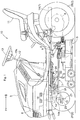
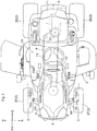
- a direction denoted with an arrow F in Fig. 1 and Fig. 2 represents a "vehicle body front side”
- a direction denoted with an arrow B in Fig. 1 and Fig. 2 represents a “vehicle body rear side”
- a direction denoted with an arrow L in Fig. 2 represents a "vehicle body left side”
- a direction denoted with an arrow R in Fig. 2 represents a "vehicle body right side”, respectively.
- Fig. 1 and Fig. 2 show a grass mower (a mid-mount type grass mower) corresponding to a "work vehicle” to which the present invention relates.
- This grass mower includes a vehicle body frame 1, and a wheel-type traveling device 2 that supports the vehicle body frame 1.
- the vehicle body frame 1 includes a pair of left and right main frames 1A that extend in the vehicle body front-rear direction.
- the traveling device 2 includes a pair of left and right steerable front wheels 2F (corresponding to "steerable wheels” relating to the present invention) and a pair of left and right drivable rear wheels 2B (corresponding to "drivable wheels” relating to the present invention).
- a hood 3 is mounted at a front half portion of the vehicle body frame 1. Inside this hood 3, there is accommodated an engine 4 acting as a driving source for the traveling device 2, etc.
- a mower unit 5 is provided between the front wheels 2F and the rear wheels 2B.
- This mower unit 5 is supported in a suspended manner to the vehicle body frame 1 via a lift mechanism 6 so that the mower unit 5 can be lifted up/down.
- a mower belt transmission mechanism 7 configured to transmit a driving force of the engine 4 to the mower unit 5.
- a transmission 8 that speed-changes the driving force of the engine 4 and transmits the resultant speed-changed force to the pair of left and right rear wheels 2B.
- a traveling belt transmission mechanism 9 that transmits the driving force of the engine 4 to the transmission 8.
- This driving section 10 includes a driver's seat 11 and a front panel 12.
- the front panel 12 includes a steering wheel 13 (corresponding to "a steering wheel” relating to the present invention) for steering the front wheels 2F.
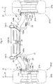
- a front axle frame 14 (corresponding to “an axle frame” relating to the present invention) that supports the pair of left and right front wheels 2F.
- a boss portion 14a which pivotally supports the corresponding front wheel 2F about a steering axis Z1 via a kingpin 15.
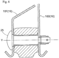
- the front axle frame 14 is supported to a mount bracket 16 to be pivotable about a pivot axis Y extending in the vehicle body front-rear direction.
- the steering wheel 13 is rotatably supported to a steering support frame 17 via a steering shaft 13a.
- the steering support frame 17 is supported to a deck 18.
- the deck 18 is provided between the pair of left and right main frames 1A.
- a lower end portion of the steering shaft 13a protrudes downwards from the deck 18.
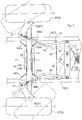
- a coupling mechanism 21 is provided for operably coupling the steering shaft 13a with the kingpin 15.
- This coupling mechanism 21 includes a steering arm 22, a pair of left and right kingpin arms 23 (corresponding to “arm members” relating to the present invention) and a pair of left and right drag links 24 (corresponding to "link members” relating to the present invention).
- the steering arm 22 is integrally fixed to the sector gear 19.
- the sector gear 19 is supported to the deck 18 to be pivotable about a pivot axis Z2 extending in the vertical direction.
- rear end portions of the drag links 24 are pivotally connected.
- the kingpin arm 23 is connected to the kingpin 15 to be pivotable together with this kingpin 15.
- front end portions of the drag links 24 are pivotally connected.
- the mount bracket 16 is provided between the pair of left and right main frames 1A.
- the mount bracket 16 includes a front bracket 16F disposed on the front side of the front axle frame 14 and a rear bracket 16B disposed on the rear side of the front axle frame 14.
- the front axle frame 14 is mounted via a mount pin 25 to be sandwiched from the front and rear sides between the front bracket 16F and the rear bracket 16R (see Fig. 6 ).
- front sloped portions 16Fa are formed respectively. Each front sloped portion 16Fa is sloped in such a manner that its lower end side is disposed progressively closer to the left-right center side of the vehicle body.
- rear sloped portions 16Ba are formed respectively. Each rear sloped portion 16Ba is sloped in such a manner that its lower end side is disposed progressively closer to the left-right center side of the vehicle body.
- a recess 16Bb On the vehicle body lateral outer side of the rear sloped portion 16Ba, there is formed a recess 16Bb for avoiding interference with the corresponding drag link 24. This arrangement serves to increase a movable range of the drag link 24, so that the turning radius of the vehicle body can be reduced advantageously.
- the kingpin 15 is provided in a form of a generally L-shape member extending between the front wheel 2F and the boss portion 14a.
- the kingpin 15 includes a lateral shaft portion 15A to which the front wheel 2F is attached and a vertical shaft portion 15B which is to be attached to the boss portion 14a.
- the vertical shaft portion 15B is inserted into the boss portion 14a via a bush 26.
- a bearing can be provided such that the vertical shaft portion 15B will be inserted into the boss portion 14a via the bearing.
- a stopper washer 27 is fixed via a bolt 28.
- the stopper means for the vertical shaft portion 15B is not limited to the above-described stopper means using the washer 27, but can be any other stopper means.
- a wheel portion 2FA of the front wheel 2F is rotatably supported via a bearing 29.
- the boss portion 14a is closer to toward a width center C of the front wheel 2F than a vehicle body lateral inner end of a tire portion 2FB of the front wheel 2F and also is closer to the width center C of the front wheel 2F than a vehicle body lateral inner end of the wheel portion 2FA of the front wheel 2F.
- its axis (steering axis Z1) is inclined towards the vehicle body lateral inner side as seen in a front view.
- the front wheel 2F is set with a kingpin angle ( ⁇ ) that defines an inclination of the steering axis Z1 towards the vehicle body lateral inner side as seen in the front view.
- the boss portion 14a its axis (steering axis Z1) is inclined also towards the rear side as seen in a side view.
- the front wheel 2F is set with a caster angle ( ⁇ ) that defines an inclination of the steering axis Z1 rearwards as seen in the side view.
- the present invention is applicable not only to a grass mower, but also to e.g. a utility vehicle, a tractor, a rice planter, a combine, etc. Further, this invention is applicable not only to an agricultural work vehicle, but also to a civil engineering work vehicle.
Landscapes
- Engineering & Computer Science (AREA)
- Chemical & Material Sciences (AREA)
- Combustion & Propulsion (AREA)
- Transportation (AREA)
- Mechanical Engineering (AREA)
- Life Sciences & Earth Sciences (AREA)
- Environmental Sciences (AREA)
- Harvester Elements (AREA)
- Steering-Linkage Mechanisms And Four-Wheel Steering (AREA)
Claims (6)
- Nutzfahrzeug, umfassend:ein Paar aus einem linken und einem rechten lenkbaren Rad (2F),ein Paar aus einem linken und einem rechten antreibbaren Rad (2B),einen Achsrahmen (14) undeinen Achsschenkelbolzen (15), der das ihm entsprechende linke/rechte lenkbare Rad (2F) an dem Achsrahmen (14) hält, sodass das lenkbare Rad (2F) um eine Lenkachse (Z1) relativ zu dem Achsrahmen (14) schwenkbar ist,dadurch gekennzeichnet, dassein Nabenabschnitt (14a), der das lenkbare Rad (2F) anhand des Achsschenkelbolzens (15) schwenkbar um eine Lenkachse (Z1) hält, an jedem von dem linken und rechten Endabschnitt des Achsrahmens (14) ausgebildet ist, wobei der Nabenabschnitt (14a) einer Breitenmitte (C) des lenkbaren Rads (2F) näher ist als einem inneren lateralen Fahrzeugkarosserieseitenende des lenkbaren Rads (2F), undder Achsschenkelbolzen (15) eine annähernde Großes-L-Form aufweist und sich zwischen dem lenkbaren Rad (2F) und dem Nabenabschnitt (14a) erstreckt.
- Nutzfahrzeug nach Anspruch 1, dadurch gekennzeichnet, dass das lenkbare Rad (2F) mit einem Nachlaufwinkel (β) eingestellt ist, der eine Neigung der Lenkachse (Z1) nach hinten definiert, wie es in einer Seitenansicht zu erkennen ist.
- Nutzfahrzeug nach Anspruch 1 oder 2, dadurch gekennzeichnet, dass das lenkbare Rad (2F) mit einem Achsschenkelbolzenwinkel (α) eingestellt ist, der eine Neigung der Lenkachse (Z1) zu einer in der Seitenansicht gesehen lateral inneren Fahrzeugkarosserieseite definiert.
- Nutzfahrzeug nach einem der vorhergehenden Ansprüche, dadurch gekennzeichnet, dass das Nutzfahrzeug ferner umfasst:ein Betätigungselement (13) zum Lenken des lenkbaren Rads (2F) undein Verbindungselement (24), das dazu ausgestaltet ist, eine Wirkverbindung zwischen dem Betätigungselement (13) und den lenkbaren Rädern (2F) zu schaffen, unddass der Achsschenkelbolzen (15) ein Armelement (23) aufweist, mit welchem das Verbindungselement (24) verbunden ist.
- Nutzfahrzeug nach Anspruch 4, dadurch gekennzeichnet, dass das Nutzfahrzeug ferner umfasst:einen Achsrahmen (14), der das Paar aus einem linken und einem rechten lenkbaren Rad (2F) hält, undeine Aufhängungshalterung (16), an welcher der Achsrahmen (14) angebracht ist, unddass die Aufhängungshalterung (16) eine Ausnehmung (16Bb) umfasst, um einen störenden Kontakt mit dem Verbindungselement (24) zu verhindern.
- Nutzfahrzeug nach einem der vorhergehenden Ansprüche, dadurch gekennzeichnet, dass das Nutzfahrzeug einen Rasenmäher der Zwischenachsart umfasst.
Applications Claiming Priority (1)
| Application Number | Priority Date | Filing Date | Title |
|---|---|---|---|
| US15/006,716 US9932070B2 (en) | 2016-01-26 | 2016-01-26 | Work vehicle |
Publications (2)
| Publication Number | Publication Date |
|---|---|
| EP3199427A1 EP3199427A1 (de) | 2017-08-02 |
| EP3199427B1 true EP3199427B1 (de) | 2019-03-20 |
Family
ID=57281148
Family Applications (1)
| Application Number | Title | Priority Date | Filing Date |
|---|---|---|---|
| EP16198182.4A Active EP3199427B1 (de) | 2016-01-26 | 2016-11-10 | Nutzfahrzeug |
Country Status (2)
| Country | Link |
|---|---|
| US (1) | US9932070B2 (de) |
| EP (1) | EP3199427B1 (de) |
Families Citing this family (2)
| Publication number | Priority date | Publication date | Assignee | Title |
|---|---|---|---|---|
| US12628732B2 (en) | 2022-02-04 | 2026-05-19 | Mtd Products Inc | Maintenance apparatus with conditional motor drive for caster wheels |
| GB2622081A (en) * | 2022-09-02 | 2024-03-06 | Ariens Company Ltd | A steering mechanism for a lawn tractor |
Family Cites Families (10)
| Publication number | Priority date | Publication date | Assignee | Title |
|---|---|---|---|---|
| US2347628A (en) * | 1941-05-20 | 1944-04-25 | American Steel Foundries | Tying and squaring means for car trucks |
| US2826427A (en) * | 1954-09-16 | 1958-03-11 | Rockwell Spring & Axle Co | Self-steering tandem axle arrangement |
| JPH0659769B2 (ja) * | 1987-10-19 | 1994-08-10 | 日産自動車株式会社 | ダブルリンク式サスペンション装置 |
| JPH07277215A (ja) | 1994-04-06 | 1995-10-24 | Kubota Corp | 操向装置 |
| JP3836225B2 (ja) * | 1997-09-12 | 2006-10-25 | 本田技研工業株式会社 | 鞍乗り型車両のフレーム構造 |
| JP2001246917A (ja) * | 2000-03-03 | 2001-09-11 | Honda Motor Co Ltd | 前輪懸架装置 |
| US7441788B2 (en) | 2004-07-09 | 2008-10-28 | Bombardier Recreational Products Inc. | Front drive geometry for an all-terrain vehicle |
| JP2011143837A (ja) * | 2010-01-15 | 2011-07-28 | Honda Motor Co Ltd | 不整地走行車両 |
| KR101361287B1 (ko) | 2012-05-15 | 2014-02-12 | 현대자동차주식회사 | 차량용 서스펜션 암 연결 장치 |
| AU2016211768B2 (en) | 2015-01-26 | 2018-09-13 | Mtd Products Inc | Steering assembly for a riding lawn mower |
-
2016
- 2016-01-26 US US15/006,716 patent/US9932070B2/en active Active
- 2016-11-10 EP EP16198182.4A patent/EP3199427B1/de active Active
Non-Patent Citations (1)
| Title |
|---|
| None * |
Also Published As
| Publication number | Publication date |
|---|---|
| US9932070B2 (en) | 2018-04-03 |
| US20170210417A1 (en) | 2017-07-27 |
| EP3199427A1 (de) | 2017-08-02 |
Similar Documents
| Publication | Publication Date | Title |
|---|---|---|
| EP3263371B1 (de) | Achsenvorrichtung | |
| US5531466A (en) | Vehicle having a four-wheel steering device | |
| US8789646B2 (en) | Steering apparatus of for a tractor | |
| EP2727802B1 (de) | Nutzfahrzeug | |
| US20160183454A1 (en) | Mower Unit | |
| US8910741B2 (en) | Steering device for tractor | |
| US20180072349A1 (en) | Utility vehicle | |
| US20200207199A1 (en) | Electric Work Vehicle | |
| EP3199427A1 (de) | Nutzfahrzeug | |
| US5299821A (en) | Compound steering mechanism with front mounted implement attachment apparatus | |
| JPH11208537A (ja) | 農用トラクタ | |
| JPS6114881Y2 (de) | ||
| JPH0958512A (ja) | 4輪ステアリング形式のミッドマウント型乗用芝刈機 | |
| JPH0733975Y2 (ja) | 芝刈機 | |
| JPS5937429Y2 (ja) | 農作業車走行装置 | |
| JP4083133B2 (ja) | 四輪駆動型作業車の操向構造 | |
| JPS638488Y2 (de) | ||
| JP2539044Y2 (ja) | 農作業機の車台構造 | |
| JP2021136930A (ja) | 作業車及び作業車のためのカウンターウェイト | |
| JP2022014154A (ja) | 乗用作業機 | |
| JPH04103406U (ja) | 乗用型芝刈機 | |
| JPH02204168A (ja) | 乗用型作業車の運転部構造 | |
| JP2004203356A (ja) | 乗用型作業車 | |
| JP2007159478A (ja) | 昇降リンク構造 | |
| JPS63173756A (ja) | ステアリング系のフレ−ム内配置構造 |
Legal Events
| Date | Code | Title | Description |
|---|---|---|---|
| PUAI | Public reference made under article 153(3) epc to a published international application that has entered the european phase |
Free format text: ORIGINAL CODE: 0009012 |
|
| STAA | Information on the status of an ep patent application or granted ep patent |
Free format text: STATUS: THE APPLICATION HAS BEEN PUBLISHED |
|
| AK | Designated contracting states |
Kind code of ref document: A1 Designated state(s): AL AT BE BG CH CY CZ DE DK EE ES FI FR GB GR HR HU IE IS IT LI LT LU LV MC MK MT NL NO PL PT RO RS SE SI SK SM TR |
|
| AX | Request for extension of the european patent |
Extension state: BA ME |
|
| STAA | Information on the status of an ep patent application or granted ep patent |
Free format text: STATUS: REQUEST FOR EXAMINATION WAS MADE |
|
| 17P | Request for examination filed |
Effective date: 20180202 |
|
| RBV | Designated contracting states (corrected) |
Designated state(s): AL AT BE BG CH CY CZ DE DK EE ES FI FR GB GR HR HU IE IS IT LI LT LU LV MC MK MT NL NO PL PT RO RS SE SI SK SM TR |
|
| GRAP | Despatch of communication of intention to grant a patent |
Free format text: ORIGINAL CODE: EPIDOSNIGR1 |
|
| STAA | Information on the status of an ep patent application or granted ep patent |
Free format text: STATUS: GRANT OF PATENT IS INTENDED |
|
| RIC1 | Information provided on ipc code assigned before grant |
Ipc: B62D 7/18 20060101AFI20180830BHEP Ipc: B62D 7/16 20060101ALI20180830BHEP Ipc: A01D 34/64 20060101ALI20180830BHEP |
|
| INTG | Intention to grant announced |
Effective date: 20181002 |
|
| GRAS | Grant fee paid |
Free format text: ORIGINAL CODE: EPIDOSNIGR3 |
|
| GRAA | (expected) grant |
Free format text: ORIGINAL CODE: 0009210 |
|
| STAA | Information on the status of an ep patent application or granted ep patent |
Free format text: STATUS: THE PATENT HAS BEEN GRANTED |
|
| AK | Designated contracting states |
Kind code of ref document: B1 Designated state(s): AL AT BE BG CH CY CZ DE DK EE ES FI FR GB GR HR HU IE IS IT LI LT LU LV MC MK MT NL NO PL PT RO RS SE SI SK SM TR |
|
| REG | Reference to a national code |
Ref country code: GB Ref legal event code: FG4D |
|
| REG | Reference to a national code |
Ref country code: CH Ref legal event code: EP |
|
| REG | Reference to a national code |
Ref country code: DE Ref legal event code: R096 Ref document number: 602016011241 Country of ref document: DE |
|
| REG | Reference to a national code |
Ref country code: AT Ref legal event code: REF Ref document number: 1110230 Country of ref document: AT Kind code of ref document: T Effective date: 20190415 |
|
| REG | Reference to a national code |
Ref country code: IE Ref legal event code: FG4D |
|
| REG | Reference to a national code |
Ref country code: NL Ref legal event code: MP Effective date: 20190320 |
|
| PG25 | Lapsed in a contracting state [announced via postgrant information from national office to epo] |
Ref country code: SE Free format text: LAPSE BECAUSE OF FAILURE TO SUBMIT A TRANSLATION OF THE DESCRIPTION OR TO PAY THE FEE WITHIN THE PRESCRIBED TIME-LIMIT Effective date: 20190320 Ref country code: FI Free format text: LAPSE BECAUSE OF FAILURE TO SUBMIT A TRANSLATION OF THE DESCRIPTION OR TO PAY THE FEE WITHIN THE PRESCRIBED TIME-LIMIT Effective date: 20190320 Ref country code: NO Free format text: LAPSE BECAUSE OF FAILURE TO SUBMIT A TRANSLATION OF THE DESCRIPTION OR TO PAY THE FEE WITHIN THE PRESCRIBED TIME-LIMIT Effective date: 20190620 Ref country code: LT Free format text: LAPSE BECAUSE OF FAILURE TO SUBMIT A TRANSLATION OF THE DESCRIPTION OR TO PAY THE FEE WITHIN THE PRESCRIBED TIME-LIMIT Effective date: 20190320 |
|
| REG | Reference to a national code |
Ref country code: LT Ref legal event code: MG4D |
|
| PG25 | Lapsed in a contracting state [announced via postgrant information from national office to epo] |
Ref country code: GR Free format text: LAPSE BECAUSE OF FAILURE TO SUBMIT A TRANSLATION OF THE DESCRIPTION OR TO PAY THE FEE WITHIN THE PRESCRIBED TIME-LIMIT Effective date: 20190621 Ref country code: HR Free format text: LAPSE BECAUSE OF FAILURE TO SUBMIT A TRANSLATION OF THE DESCRIPTION OR TO PAY THE FEE WITHIN THE PRESCRIBED TIME-LIMIT Effective date: 20190320 Ref country code: LV Free format text: LAPSE BECAUSE OF FAILURE TO SUBMIT A TRANSLATION OF THE DESCRIPTION OR TO PAY THE FEE WITHIN THE PRESCRIBED TIME-LIMIT Effective date: 20190320 Ref country code: NL Free format text: LAPSE BECAUSE OF FAILURE TO SUBMIT A TRANSLATION OF THE DESCRIPTION OR TO PAY THE FEE WITHIN THE PRESCRIBED TIME-LIMIT Effective date: 20190320 Ref country code: RS Free format text: LAPSE BECAUSE OF FAILURE TO SUBMIT A TRANSLATION OF THE DESCRIPTION OR TO PAY THE FEE WITHIN THE PRESCRIBED TIME-LIMIT Effective date: 20190320 Ref country code: BG Free format text: LAPSE BECAUSE OF FAILURE TO SUBMIT A TRANSLATION OF THE DESCRIPTION OR TO PAY THE FEE WITHIN THE PRESCRIBED TIME-LIMIT Effective date: 20190620 |
|
| REG | Reference to a national code |
Ref country code: AT Ref legal event code: MK05 Ref document number: 1110230 Country of ref document: AT Kind code of ref document: T Effective date: 20190320 |
|
| PG25 | Lapsed in a contracting state [announced via postgrant information from national office to epo] |
Ref country code: CZ Free format text: LAPSE BECAUSE OF FAILURE TO SUBMIT A TRANSLATION OF THE DESCRIPTION OR TO PAY THE FEE WITHIN THE PRESCRIBED TIME-LIMIT Effective date: 20190320 Ref country code: IT Free format text: LAPSE BECAUSE OF FAILURE TO SUBMIT A TRANSLATION OF THE DESCRIPTION OR TO PAY THE FEE WITHIN THE PRESCRIBED TIME-LIMIT Effective date: 20190320 Ref country code: ES Free format text: LAPSE BECAUSE OF FAILURE TO SUBMIT A TRANSLATION OF THE DESCRIPTION OR TO PAY THE FEE WITHIN THE PRESCRIBED TIME-LIMIT Effective date: 20190320 Ref country code: RO Free format text: LAPSE BECAUSE OF FAILURE TO SUBMIT A TRANSLATION OF THE DESCRIPTION OR TO PAY THE FEE WITHIN THE PRESCRIBED TIME-LIMIT Effective date: 20190320 Ref country code: EE Free format text: LAPSE BECAUSE OF FAILURE TO SUBMIT A TRANSLATION OF THE DESCRIPTION OR TO PAY THE FEE WITHIN THE PRESCRIBED TIME-LIMIT Effective date: 20190320 Ref country code: AL Free format text: LAPSE BECAUSE OF FAILURE TO SUBMIT A TRANSLATION OF THE DESCRIPTION OR TO PAY THE FEE WITHIN THE PRESCRIBED TIME-LIMIT Effective date: 20190320 Ref country code: SK Free format text: LAPSE BECAUSE OF FAILURE TO SUBMIT A TRANSLATION OF THE DESCRIPTION OR TO PAY THE FEE WITHIN THE PRESCRIBED TIME-LIMIT Effective date: 20190320 Ref country code: PT Free format text: LAPSE BECAUSE OF FAILURE TO SUBMIT A TRANSLATION OF THE DESCRIPTION OR TO PAY THE FEE WITHIN THE PRESCRIBED TIME-LIMIT Effective date: 20190720 |
|
| PG25 | Lapsed in a contracting state [announced via postgrant information from national office to epo] |
Ref country code: PL Free format text: LAPSE BECAUSE OF FAILURE TO SUBMIT A TRANSLATION OF THE DESCRIPTION OR TO PAY THE FEE WITHIN THE PRESCRIBED TIME-LIMIT Effective date: 20190320 Ref country code: SM Free format text: LAPSE BECAUSE OF FAILURE TO SUBMIT A TRANSLATION OF THE DESCRIPTION OR TO PAY THE FEE WITHIN THE PRESCRIBED TIME-LIMIT Effective date: 20190320 |
|
| PG25 | Lapsed in a contracting state [announced via postgrant information from national office to epo] |
Ref country code: AT Free format text: LAPSE BECAUSE OF FAILURE TO SUBMIT A TRANSLATION OF THE DESCRIPTION OR TO PAY THE FEE WITHIN THE PRESCRIBED TIME-LIMIT Effective date: 20190320 Ref country code: IS Free format text: LAPSE BECAUSE OF FAILURE TO SUBMIT A TRANSLATION OF THE DESCRIPTION OR TO PAY THE FEE WITHIN THE PRESCRIBED TIME-LIMIT Effective date: 20190720 |
|
| REG | Reference to a national code |
Ref country code: DE Ref legal event code: R097 Ref document number: 602016011241 Country of ref document: DE |
|
| PLBE | No opposition filed within time limit |
Free format text: ORIGINAL CODE: 0009261 |
|
| STAA | Information on the status of an ep patent application or granted ep patent |
Free format text: STATUS: NO OPPOSITION FILED WITHIN TIME LIMIT |
|
| PG25 | Lapsed in a contracting state [announced via postgrant information from national office to epo] |
Ref country code: DK Free format text: LAPSE BECAUSE OF FAILURE TO SUBMIT A TRANSLATION OF THE DESCRIPTION OR TO PAY THE FEE WITHIN THE PRESCRIBED TIME-LIMIT Effective date: 20190320 |
|
| 26N | No opposition filed |
Effective date: 20200102 |
|
| PG25 | Lapsed in a contracting state [announced via postgrant information from national office to epo] |
Ref country code: SI Free format text: LAPSE BECAUSE OF FAILURE TO SUBMIT A TRANSLATION OF THE DESCRIPTION OR TO PAY THE FEE WITHIN THE PRESCRIBED TIME-LIMIT Effective date: 20190320 |
|
| PG25 | Lapsed in a contracting state [announced via postgrant information from national office to epo] |
Ref country code: TR Free format text: LAPSE BECAUSE OF FAILURE TO SUBMIT A TRANSLATION OF THE DESCRIPTION OR TO PAY THE FEE WITHIN THE PRESCRIBED TIME-LIMIT Effective date: 20190320 |
|
| REG | Reference to a national code |
Ref country code: DE Ref legal event code: R119 Ref document number: 602016011241 Country of ref document: DE |
|
| REG | Reference to a national code |
Ref country code: CH Ref legal event code: PL |
|
| PG25 | Lapsed in a contracting state [announced via postgrant information from national office to epo] |
Ref country code: LU Free format text: LAPSE BECAUSE OF NON-PAYMENT OF DUE FEES Effective date: 20191110 Ref country code: LI Free format text: LAPSE BECAUSE OF NON-PAYMENT OF DUE FEES Effective date: 20191130 Ref country code: MC Free format text: LAPSE BECAUSE OF FAILURE TO SUBMIT A TRANSLATION OF THE DESCRIPTION OR TO PAY THE FEE WITHIN THE PRESCRIBED TIME-LIMIT Effective date: 20190320 Ref country code: CH Free format text: LAPSE BECAUSE OF NON-PAYMENT OF DUE FEES Effective date: 20191130 |
|
| REG | Reference to a national code |
Ref country code: BE Ref legal event code: MM Effective date: 20191130 |
|
| PG25 | Lapsed in a contracting state [announced via postgrant information from national office to epo] |
Ref country code: IE Free format text: LAPSE BECAUSE OF NON-PAYMENT OF DUE FEES Effective date: 20191110 Ref country code: DE Free format text: LAPSE BECAUSE OF NON-PAYMENT OF DUE FEES Effective date: 20200603 |
|
| PG25 | Lapsed in a contracting state [announced via postgrant information from national office to epo] |
Ref country code: BE Free format text: LAPSE BECAUSE OF NON-PAYMENT OF DUE FEES Effective date: 20191130 |
|
| PG25 | Lapsed in a contracting state [announced via postgrant information from national office to epo] |
Ref country code: CY Free format text: LAPSE BECAUSE OF FAILURE TO SUBMIT A TRANSLATION OF THE DESCRIPTION OR TO PAY THE FEE WITHIN THE PRESCRIBED TIME-LIMIT Effective date: 20190320 |
|
| GBPC | Gb: european patent ceased through non-payment of renewal fee |
Effective date: 20201110 |
|
| PG25 | Lapsed in a contracting state [announced via postgrant information from national office to epo] |
Ref country code: HU Free format text: LAPSE BECAUSE OF FAILURE TO SUBMIT A TRANSLATION OF THE DESCRIPTION OR TO PAY THE FEE WITHIN THE PRESCRIBED TIME-LIMIT; INVALID AB INITIO Effective date: 20161110 Ref country code: MT Free format text: LAPSE BECAUSE OF FAILURE TO SUBMIT A TRANSLATION OF THE DESCRIPTION OR TO PAY THE FEE WITHIN THE PRESCRIBED TIME-LIMIT Effective date: 20190320 |
|
| PG25 | Lapsed in a contracting state [announced via postgrant information from national office to epo] |
Ref country code: GB Free format text: LAPSE BECAUSE OF NON-PAYMENT OF DUE FEES Effective date: 20201110 |
|
| PG25 | Lapsed in a contracting state [announced via postgrant information from national office to epo] |
Ref country code: MK Free format text: LAPSE BECAUSE OF FAILURE TO SUBMIT A TRANSLATION OF THE DESCRIPTION OR TO PAY THE FEE WITHIN THE PRESCRIBED TIME-LIMIT Effective date: 20190320 |
|
| PGFP | Annual fee paid to national office [announced via postgrant information from national office to epo] |
Ref country code: FR Payment date: 20250930 Year of fee payment: 10 |