EP3199499A1 - Procédé de découpe d'un substrat cassant - Google Patents
Procédé de découpe d'un substrat cassant Download PDFInfo
- Publication number
- EP3199499A1 EP3199499A1 EP15843968.7A EP15843968A EP3199499A1 EP 3199499 A1 EP3199499 A1 EP 3199499A1 EP 15843968 A EP15843968 A EP 15843968A EP 3199499 A1 EP3199499 A1 EP 3199499A1
- Authority
- EP
- European Patent Office
- Prior art keywords
- line
- brittle substrate
- crack
- trench line
- forming
- Prior art date
- Legal status (The legal status is an assumption and is not a legal conclusion. Google has not performed a legal analysis and makes no representation as to the accuracy of the status listed.)
- Withdrawn
Links
Images


Classifications
-
- H—ELECTRICITY
- H10—SEMICONDUCTOR DEVICES; ELECTRIC SOLID-STATE DEVICES NOT OTHERWISE PROVIDED FOR
- H10P—GENERIC PROCESSES OR APPARATUS FOR THE MANUFACTURE OR TREATMENT OF DEVICES COVERED BY CLASS H10
- H10P54/00—Cutting or separating of wafers, substrates or parts of devices
-
- B—PERFORMING OPERATIONS; TRANSPORTING
- B28—WORKING CEMENT, CLAY, OR STONE
- B28D—WORKING STONE OR STONE-LIKE MATERIALS
- B28D5/00—Fine working of gems, jewels, crystals, e.g. of semiconductor material; apparatus or devices therefor
- B28D5/0005—Fine working of gems, jewels, crystals, e.g. of semiconductor material; apparatus or devices therefor by breaking, e.g. dicing
- B28D5/0011—Fine working of gems, jewels, crystals, e.g. of semiconductor material; apparatus or devices therefor by breaking, e.g. dicing with preliminary treatment, e.g. weakening by scoring
-
- B—PERFORMING OPERATIONS; TRANSPORTING
- B28—WORKING CEMENT, CLAY, OR STONE
- B28D—WORKING STONE OR STONE-LIKE MATERIALS
- B28D5/00—Fine working of gems, jewels, crystals, e.g. of semiconductor material; apparatus or devices therefor
-
- B—PERFORMING OPERATIONS; TRANSPORTING
- B28—WORKING CEMENT, CLAY, OR STONE
- B28D—WORKING STONE OR STONE-LIKE MATERIALS
- B28D5/00—Fine working of gems, jewels, crystals, e.g. of semiconductor material; apparatus or devices therefor
- B28D5/0005—Fine working of gems, jewels, crystals, e.g. of semiconductor material; apparatus or devices therefor by breaking, e.g. dicing
- B28D5/0017—Fine working of gems, jewels, crystals, e.g. of semiconductor material; apparatus or devices therefor by breaking, e.g. dicing using moving tools
-
- C—CHEMISTRY; METALLURGY
- C03—GLASS; MINERAL OR SLAG WOOL
- C03B—MANUFACTURE, SHAPING, OR SUPPLEMENTARY PROCESSES
- C03B33/00—Severing cooled glass
- C03B33/02—Cutting or splitting sheet glass or ribbons; Apparatus or machines therefor
- C03B33/04—Cutting or splitting in curves, especially for making spectacle lenses
-
- H—ELECTRICITY
- H10—SEMICONDUCTOR DEVICES; ELECTRIC SOLID-STATE DEVICES NOT OTHERWISE PROVIDED FOR
- H10W—GENERIC PACKAGES, INTERCONNECTIONS, CONNECTORS OR OTHER CONSTRUCTIONAL DETAILS OF DEVICES COVERED BY CLASS H10
- H10W10/00—Isolation regions in semiconductor bodies between components of integrated devices
- H10W10/01—Manufacture or treatment
Definitions
- the present invention relates to a method for dividing a brittle substrate.
- Patent Document 1 while a cutter is brought into pressure contact with a front surface of a brittle substrate, at least one of the brittle-material substrate and the cutter is moved to draw a closed curve to form a scribe line formed of a crack. Thereafter, stress is applied to the brittle-material substrate to cause the crack to grow to a back surface of the brittle-material substrate, and then the brittle-material substrate is divided.
- Patent Document 1 Japanese Patent Application Laid-Open No. 2010-173905
- the present invention has been made to solve the problem described above, and an object thereof is to provide a method for dividing a brittle substrate, the method capable of uniformly dividing a brittle substrate along a shape including a curved portion.
- a method for dividing a brittle substrate of the present invention includes the following steps.
- a brittle substrate including a surface and having a thickness direction perpendicular to the surface is prepared.
- a cutter edge is pressed against the surface of the brittle substrate.
- a trench line having a groove shape is formed by causing the pressed cutter edge to slide on the surface of the brittle substrate to generate plastic deformation on the surface of the brittle substrate.
- the forming a trench line is performed to obtain a crack-free state, in which the brittle substrate seamlessly continues in a direction intersecting the trench line directly below the trench line.
- the trench line includes a curved portion.
- a crack line is formed by extending a crack of the brittle substrate in the thickness direction along the trench line.
- the crack line breaks seamless continuity of the brittle substrate in the direction intersecting the trench line directly below the trench line.
- a shape into which the brittle substrate is divided is defined by a shape of the trench line.
- the trench line can be uniformly formed even if the trench line includes a curved portion. This enables a brittle substrate to be uniformly divided along a shape including a curved portion.
- a glass substrate 4 (brittle substrate) is prepared ( Fig. 2 : step S10).
- the glass substrate 4 has a surface SF.
- a cutting tool 50 including a cutter edge 51 and a shank 52 is prepared.
- the cutter edge 51 is fixed to and held by the shank 52 serving as a holder.
- the cutter edge 51 is provided with a top surface SD1 (first surface) and a plurality of surfaces surrounding the top surface SD1.
- the plurality of surfaces includes a side surface SD2 (second surface) and a side surface SD3 (third surface).
- the top surface SD1, and the side surfaces SD2 and SD3 (the first to third surfaces) are oriented in different directions and are adjacent to each other.
- the cutter edge 51 has a vertex at which the top surface SD1 and the side surfaces SD2 and SD3 meet, and the vertex forms a protruding portion PP of the cutter edge 51.
- the side surfaces SD2 and SD3 form a ridge forming a side portion PS of the cutter edge 51.
- the side portion PS extends in a line from the protruding portion PP.
- the side portion PS is a ridge as described above, and thus has a convex shape extending in a line.
- the cutter edge 51 is a diamond point. That is, it is preferable that the cutter edge 51 is made of diamond in terms of hardness and reduced surface roughness. More preferably, the cutter edge 51 is made of single-crystal diamond. Still more preferably, in crystallography, the top surface SD1 is a ⁇ 001 ⁇ plane, and each of the side surfaces SD2 and SD3 is a ⁇ 111 ⁇ plane. In this case, the side surfaces SD2 and SD3 are crystal planes equivalent to each other in crystallography, although they have different directions.
- Diamond other than single-crystal diamond may be used, and for example, polycrystalline diamond synthesized by chemical vapor deposition (CVD) may be used.
- CVD chemical vapor deposition
- polycrystalline diamond sintered from particulate graphite or non-graphitic carbon without containing a binder such as iron group elements, or sintered diamond obtained by binding diamond particles with a binder such as iron group elements, may be used.
- the shank 52 extends along an axial direction AX. It is preferable that the cutter edge 51 is attached to the shank 52 such that the direction normal to the top surface SD1 extends substantially along the axial direction AX.
- the cutter edge 51 is then pressed against the surface SF of the glass substrate 4 at a starting point NS (one location) ( Fig. 2 : step S20). Specifically, the protruding portion PP and the side portion PS of the cutter edge 51 are pressed in a thickness direction DT of the glass substrate 4.
- the pressed cutter edge 51 is slid in a direction DA from the starting point NS on the surface SF of the glass substrate 4.
- the direction DA is obtained by projecting, on the surface SF, a direction extending from the protruding portion PP along the side portion PS, and substantially corresponds to a direction in which the axial direction AX is projected on the surface SF.
- the cutter edge 51 is dragged on the surface SF by the shank 52.
- a position NC of the sliding cutter edge 51 defines a path including a curved portion, and ultimately approaches the starting point NS again.
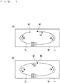
- the above sliding causes plastic deformation on the surface SF of the glass substrate 4, thereby forming a trench line TL having a groove shape ( Fig. 4(A) ) ( Fig. 2 : step S30).
- the trench line TL includes a curved portion corresponding to the path of the position NC of the cutter edge 51.
- the curved portion may include a curvature radius of 5 mm or less.
- a step of forming the trench line TL is performed to obtain a crack-free state, in which the glass substrate 4 seamlessly continues in a direction DC intersecting the trench line TL directly below the trench line TL.
- the crack-free state although the trench line TL is formed through the plastic deformation, no crack is formed along the trench line TL.
- a load applied to the cutter edge 51 is set to be small so as to cause no crack and large so as to cause the plastic deformation.
- the cutter edge 51 is further slid to return the position NC of the cutter edge 51 to the starting point NS.
- This forms the trench line TL forming a closed curve including the starting point NS.
- the closed curve may include a straight portion in addition to the curved portion.
- the position NC of the cutter edge 51 is returned to the starting point NS to start forming a crack line CL ( Fig. 4(B) ) in a direction EA along the trench line TL ( Fig. 2 : step S40).
- the crack line CL is formed by extending a crack of the glass substrate 4 in the thickness direction DT along the trench line TL.
- the crack line CL is a crack extending from a dent of the trench line TL in the thickness direction DT, and extends in a line on the surface SF.
- the crack line CL breaks seamless continuity of the glass substrate 4 in the direction DC ( Fig. 4(B) ) intersecting the trench line TL directly below the trench line TL.
- the "seamless continuity" herein refers to the continuity that is not interrupted by a crack.
- portions of the glass substrate 4 may be in contact with each other with the crack of the crack line CL therebetween.
- the direction EA in which the crack extends along the trench line TL is opposite to the direction DA ( Fig. 1(A) ) in which the cutter edge 51 slides in the step of forming the trench line TL. That is, there is directional dependence that affects easiness of extension of the crack line CL. It is assumed that the directional dependence is caused by distribution of internal stress generated in the glass substrate 4 when the trench line TL is formed.
- the scribe line described above includes a trench line TL and a crack line CL ( Fig. 3(B) ) that are simultaneously formed by sliding or rolling of the cutter edge 51, and the timing of forming the crack line CL is different from that of the present embodiment.
- the glass substrate 4 is divided along the crack line CL ( Fig. 2 : step S50). That is, so-called a breaking step is performed.
- the breaking step can be performed by applying external force to the glass substrate 4 to bend the glass substrate 4.
- the glass substrate 4 can be divided at the same time when the crack line CL is formed. In this case, the breaking step can be omitted.
- a shape into which the glass substrate 4 is divided is defined by a shape of the trench line TL.
- the trench line TL can be uniformly formed even if the trench line TL includes a curved portion. Accordingly, the glass substrate 4 can be uniformly divided along the shape including the curved portion.
- a curved portion has a curvature radius of 5 mm or less, a significant effect is obtained by application of the present embodiment.
- a cutter edge 51 pressed against a surface SF of a glass substrate 4 at a starting point NS (one location) is slid in a direction DB instead of the direction DA.
- the direction DB is obtained by projecting, on the surface SF, a direction extending to a protruding portion PP along a side portion PS (refer to Figs. 3(A) and 3(B) ), and substantially corresponds to a direction opposite to the direction in which an axial direction AX is projected on the surface SF.
- the cutter edge 51 is pressed forward on the surface SF by a shank 52.
- the above sliding forms a trench line TL ( Fig. 4(A) ).
- a position NC of the cutter edge 51 is returned to the starting point NS to start forming a crack line CL ( Fig. 4(B) ) in a direction EB along the trench line TL ( Fig. 2 : step S40).
- the direction EB in which a crack extends along the trench line TL is identical to the direction DA ( Fig. 1(A) ) in which the cutter edge 51 slides in the step of forming the trench line TL.
- a cutter edge 51 ( Fig. 3(A) and (B) ) pressed against a surface SF of a glass substrate 4 at a starting point NS is slid in a direction DA to an ending point NE away from the starting point NS.
- This sliding forms a trench line TL including a curved portion ( Fig. 4(A) ).
- the cutter edge 51 that has reached the ending point NE is moved away from the surface SF of the glass substrate 4.
- a step of forming a crack line CL is started by applying stress to the glass substrate 4 on the trench line TL.
- a scribe line SL intersecting the trench line TL is formed on the surface SF of the glass substrate 4.
- the scribe line SL intersects the trench line TL at each of intersections Na and Nb. Accordingly, forming of the crack line CL is started from each of the intersections Na and Nb in a direction EA opposite to the direction DA. If sufficient stress to start forming the crack line CL is not obtained during formation of the scribe line SL, formation of the crack line CL may be started by dividing the glass substrate 4 along the scribe line SL to apply larger stress.
- both of the intersections Na and Nb are not necessarily provided, and thus only an intersection suitable for a starting point of forming the crack line CL in the direction EA may be provided.
- providing at least the intersection Na enables the crack line CL to be formed along a main section including a curved portion of the trench line TL.
- a method for applying stress is not limited to the method described above.
- the glass substrate 4 can be divided along a shape different from a closed curve.
- a cutter edge 51 ( Figs. 3(A) and 3(B) ) pressed against a surface SF of a glass substrate 4 at a starting point NS is slid in a direction DB to an ending point NE.
- This sliding forms a trench line TL including a curved portion ( Fig. 4(A) ).
- the cutter edge 51 that has reached the ending point NE is moved away from the surface SF of the glass substrate 4.
- a step of forming a crack line CL is started by applying stress to the glass substrate 4 on the trench line TL.
- a scribe line SL intersecting the trench line TL is formed on the surface SF of the glass substrate 4.
- the scribe line SL intersects the trench line TL at each of intersections Na and Nb. Accordingly, forming of the crack line CL is started from each of the intersections Na and Nb in a direction EB identical to the direction DB. If sufficient stress to start forming the crack line CL is not obtained during formation of the scribe line SL, forming of the crack line CL may be started by dividing the glass substrate 4 along the scribe line SL to apply larger stress.
- both of the intersections Na and Nb are not necessarily provided, and thus only an intersection suitable for a starting point of forming the crack line CL in the direction EB may be provided. Specifically, providing at least the intersection Nb enables the crack line CL to be formed along a main section including a curved portion of the trench line TL.
- a method for applying stress is not limited to the method described above.
- a cutter edge 51v may be used instead of the cutter edge 51 ( Figs. 3(A) and 3(B) ) in each of the above embodiments.
- the cutter edge 51v has a conical shape with a vertex and a conical surface SC.
- a protruding portion PPv of the cutter edge 51v is formed by the vertex.
- a side portion PSv of the cutter edge is formed along a virtual line (the broken line in Fig. 8(B) ) extending from the vertex on the conical surface SC. Accordingly, the side portion PSv has a convex shape extending in a line.
- the brittle substrate is not limited to the glass substrate, and thus any substrate made of brittle material may be used.
- Brittle material other than glass includes, for example, ceramic, silicon, compound semiconductor, sapphire, and quartz.
- each of the embodiments may be freely combined, or modified or omitted as appropriate within the scope of the invention.
Landscapes
- Engineering & Computer Science (AREA)
- Mechanical Engineering (AREA)
- Chemical & Material Sciences (AREA)
- Materials Engineering (AREA)
- Organic Chemistry (AREA)
- Re-Forming, After-Treatment, Cutting And Transporting Of Glass Products (AREA)
- Processing Of Stones Or Stones Resemblance Materials (AREA)
Applications Claiming Priority (2)
| Application Number | Priority Date | Filing Date | Title |
|---|---|---|---|
| JP2014194717 | 2014-09-25 | ||
| PCT/JP2015/073100 WO2016047317A1 (fr) | 2014-09-25 | 2015-08-18 | Procédé de découpe d'un substrat cassant |
Publications (2)
| Publication Number | Publication Date |
|---|---|
| EP3199499A1 true EP3199499A1 (fr) | 2017-08-02 |
| EP3199499A4 EP3199499A4 (fr) | 2018-06-06 |
Family
ID=55580848
Family Applications (1)
| Application Number | Title | Priority Date | Filing Date |
|---|---|---|---|
| EP15843968.7A Withdrawn EP3199499A4 (fr) | 2014-09-25 | 2015-08-18 | Procédé de découpe d'un substrat cassant |
Country Status (6)
| Country | Link |
|---|---|
| EP (1) | EP3199499A4 (fr) |
| JP (1) | JP6350669B2 (fr) |
| KR (1) | KR101901631B1 (fr) |
| CN (1) | CN106795035B (fr) |
| TW (1) | TWI657059B (fr) |
| WO (1) | WO2016047317A1 (fr) |
Families Citing this family (4)
| Publication number | Priority date | Publication date | Assignee | Title |
|---|---|---|---|---|
| JP6589358B2 (ja) * | 2015-04-30 | 2019-10-16 | 三星ダイヤモンド工業株式会社 | 脆性材料基板の分断方法 |
| KR102167941B1 (ko) * | 2016-05-25 | 2020-10-20 | 미쓰보시 다이야몬도 고교 가부시키가이샤 | 취성 기판의 분단 방법 |
| JP6760641B2 (ja) * | 2016-06-29 | 2020-09-23 | 三星ダイヤモンド工業株式会社 | 脆性基板の分断方法 |
| JP7255890B2 (ja) * | 2020-12-24 | 2023-04-11 | 三星ダイヤモンド工業株式会社 | 脆性材料基板の加工方法及び分断方法 |
Family Cites Families (10)
| Publication number | Priority date | Publication date | Assignee | Title |
|---|---|---|---|---|
| JPH0791078B2 (ja) * | 1988-09-27 | 1995-10-04 | 日本板硝子株式会社 | ガラス板の切抜き方法 |
| TWI226877B (en) * | 2001-07-12 | 2005-01-21 | Mitsuboshi Diamond Ind Co Ltd | Method of manufacturing adhered brittle material substrates and method of separating adhered brittle material substrates |
| JP4843180B2 (ja) * | 2002-12-12 | 2011-12-21 | 三星ダイヤモンド工業株式会社 | チップホルダー、スクライブヘッドおよびスクライブ装置ならびにスクライブ方法 |
| JP4256724B2 (ja) * | 2003-06-05 | 2009-04-22 | 三星ダイヤモンド工業株式会社 | 脆性材料基板のスクライブ方法及びその装置 |
| CN101610870B (zh) * | 2007-10-16 | 2013-09-11 | 三星钻石工业股份有限公司 | 脆性材料基板的u形槽加工方法以及使用该方法的去除加工方法、打孔加工方法和倒角方法 |
| JP2010126383A (ja) | 2008-11-26 | 2010-06-10 | Joyo Kogaku Kk | ガラス切断用カッターホイール |
| JP4836150B2 (ja) * | 2008-11-26 | 2011-12-14 | 株式会社日本製鋼所 | カッターホイール |
| TWI494284B (zh) * | 2010-03-19 | 2015-08-01 | Corning Inc | 強化玻璃之機械劃割及分離 |
| JP5244202B2 (ja) * | 2011-01-27 | 2013-07-24 | 三星ダイヤモンド工業株式会社 | 脆性材料基板のスクライブ方法 |
| WO2013161849A1 (fr) * | 2012-04-24 | 2013-10-31 | 株式会社東京精密 | Lame de découpage |
-
2015
- 2015-08-18 EP EP15843968.7A patent/EP3199499A4/fr not_active Withdrawn
- 2015-08-18 WO PCT/JP2015/073100 patent/WO2016047317A1/fr not_active Ceased
- 2015-08-18 JP JP2016550035A patent/JP6350669B2/ja not_active Expired - Fee Related
- 2015-08-18 KR KR1020177009531A patent/KR101901631B1/ko not_active Expired - Fee Related
- 2015-08-18 CN CN201580051762.7A patent/CN106795035B/zh not_active Expired - Fee Related
- 2015-08-28 TW TW104128494A patent/TWI657059B/zh not_active IP Right Cessation
Also Published As
| Publication number | Publication date |
|---|---|
| WO2016047317A1 (fr) | 2016-03-31 |
| KR20170051511A (ko) | 2017-05-11 |
| JP6350669B2 (ja) | 2018-07-04 |
| CN106795035A (zh) | 2017-05-31 |
| EP3199499A4 (fr) | 2018-06-06 |
| CN106795035B (zh) | 2019-08-27 |
| TWI657059B (zh) | 2019-04-21 |
| TW201615580A (zh) | 2016-05-01 |
| KR101901631B1 (ko) | 2018-09-27 |
| JPWO2016047317A1 (ja) | 2017-06-29 |
Similar Documents
| Publication | Publication Date | Title |
|---|---|---|
| EP3127673B1 (fr) | Procédé de découpe de substrat en matériau cassant | |
| JP2016069195A (ja) | 基板分断方法 | |
| JP6288258B2 (ja) | 脆性基板の分断方法 | |
| JP6350669B2 (ja) | 脆性基板の分断方法 | |
| TWI663134B (zh) | 脆性基板之分斷方法 | |
| KR102066120B1 (ko) | 취성 기판의 분단 방법 | |
| TWI712478B (zh) | 脆性基板之分斷方法 | |
| CN106079116B (zh) | 脆性材料基板的断开方法 | |
| TWI678343B (zh) | 脆性基板之分斷方法 | |
| CN107848862B (zh) | 脆性基板的分断方法 | |
| TWI653201B (zh) | Fragmentation method of brittle substrate | |
| KR20160000838A (ko) | 단결정 기판의 분단 방법 및 단결정 기판 | |
| TWI715718B (zh) | 脆性基板之分斷方法 | |
| TW201620843A (zh) | 脆性基板之分斷方法 | |
| JP2017065007A (ja) | 脆性基板の分断方法 |
Legal Events
| Date | Code | Title | Description |
|---|---|---|---|
| STAA | Information on the status of an ep patent application or granted ep patent |
Free format text: STATUS: THE INTERNATIONAL PUBLICATION HAS BEEN MADE |
|
| PUAI | Public reference made under article 153(3) epc to a published international application that has entered the european phase |
Free format text: ORIGINAL CODE: 0009012 |
|
| STAA | Information on the status of an ep patent application or granted ep patent |
Free format text: STATUS: REQUEST FOR EXAMINATION WAS MADE |
|
| 17P | Request for examination filed |
Effective date: 20170424 |
|
| AK | Designated contracting states |
Kind code of ref document: A1 Designated state(s): AL AT BE BG CH CY CZ DE DK EE ES FI FR GB GR HR HU IE IS IT LI LT LU LV MC MK MT NL NO PL PT RO RS SE SI SK SM TR |
|
| AX | Request for extension of the european patent |
Extension state: BA ME |
|
| DAV | Request for validation of the european patent (deleted) | ||
| DAX | Request for extension of the european patent (deleted) | ||
| A4 | Supplementary search report drawn up and despatched |
Effective date: 20180508 |
|
| RIC1 | Information provided on ipc code assigned before grant |
Ipc: C03B 33/023 20060101ALI20180502BHEP Ipc: B28D 5/00 20060101ALI20180502BHEP Ipc: B28D 1/22 20060101ALI20180502BHEP Ipc: C03B 33/033 20060101ALI20180502BHEP Ipc: C03B 33/037 20060101AFI20180502BHEP |
|
| STAA | Information on the status of an ep patent application or granted ep patent |
Free format text: STATUS: EXAMINATION IS IN PROGRESS |
|
| 17Q | First examination report despatched |
Effective date: 20210204 |
|
| STAA | Information on the status of an ep patent application or granted ep patent |
Free format text: STATUS: THE APPLICATION HAS BEEN WITHDRAWN |
|
| 18W | Application withdrawn |
Effective date: 20210408 |