EP3199675A1 - Métier à tisser comprenant un dispositif d'aspiration - Google Patents
Métier à tisser comprenant un dispositif d'aspiration Download PDFInfo
- Publication number
- EP3199675A1 EP3199675A1 EP17151981.2A EP17151981A EP3199675A1 EP 3199675 A1 EP3199675 A1 EP 3199675A1 EP 17151981 A EP17151981 A EP 17151981A EP 3199675 A1 EP3199675 A1 EP 3199675A1
- Authority
- EP
- European Patent Office
- Prior art keywords
- spinning machine
- suction
- suction device
- flow direction
- fan
- Prior art date
- Legal status (The legal status is an assumption and is not a legal conclusion. Google has not performed a legal analysis and makes no representation as to the accuracy of the status listed.)
- Granted
Links
Images


Classifications
-
- D—TEXTILES; PAPER
- D01—NATURAL OR MAN-MADE THREADS OR FIBRES; SPINNING
- D01H—SPINNING OR TWISTING
- D01H11/00—Arrangements for confining or removing dust, fly or the like
- D01H11/005—Arrangements for confining or removing dust, fly or the like with blowing and/or suction devices
Definitions
- the present invention relates to a spinning machine, in particular rotor spinning machine, with a plurality of between two front ends of the spinning machine in the longitudinal direction of the spinning machine juxtaposed jobs, each having at least one suction point. Furthermore, the spinning machine has at least one suction channel extending in the longitudinal direction of the spinning machine and at least one suction device for generating a negative pressure in the suction channel and at the suction points.
- the individual jobs have suction points, which are arranged in the case of ring spinning machines or air jet spinning machines, for example in the region of a drafting system, which is arranged at each workstation, or in the region of a spinning chamber at the air-jet nozzle. Loose fibers, dust and fiber fly are sucked off via these suction points and fed via the suction channel of a filter device which is arranged in the region of the vacuum source.
- a vacuum supply is already required for the maintenance of the spinning process.
- a suction point in the area of the spinning rotor is provided at each workstation, which ensures the necessary negative pressure in the rotor housing.
- the DE 10 2006 035 729 A1 describes a spinning machine with a suction system for spinning stations and a central device for generating negative pressure.
- the DE 10 2006 035 729 A1 deals with the problem that due to a different occupancy of the filter device it difficult to maintain controlled negative pressure conditions.
- the document therefore proposes to measure the actual level of negative pressure and to regulate the negative pressure accordingly.
- the vacuum source may comprise either an axial fan or a centrifugal fan.
- the device for generating the spinning negative pressure is intended to be arranged in the intermediate frame, so that the vacuum channel is no longer machine-length, but extends in each case from the intermediate frame in both directions towards the end frame of the machine.
- the required length of the vacuum channel is thereby reduced, so that the pressure losses in the exhaust system can be significantly reduced and there is a more uniform level of vacuum over the length of the spinning machine. Nevertheless, fans with high power are still required, which have a considerable energy requirement.
- Object of the present invention is therefore to propose a spinning machine, which the arrangement of a particularly high number of jobs allows and at the same time allows an economic operation of the suction device.
- a spinning machine has a multiplicity of workstations arranged side by side between two front ends of the spinning machine in the longitudinal direction of the spinning machine, each of which contains at least one suction point. Furthermore, the spinning machine has at least one suction channel extending in the longitudinal direction of the spinning machine and at least one suction device for generating a negative pressure in the suction channel and at the suction points. It is provided that the suction device includes at least two different areas of action, wherein at least one area of action has an axial flow direction and at least one area of action has a radial flow direction. The flow direction refers to the medium flowing through the suction device.
- the at least two areas of action in the flow direction which runs from the suction side to the pressure side, are arranged successively acting in the suction device. Unfavorable turbulences in the suction device can thereby be avoided particularly well.
- the effective range with the axial flow direction and the effective range with the radial Flow direction are arranged at least partially parallel to each other acting in the suction device.
- Particularly advantageous in terms of avoiding turbulence and increasing the efficiency of the suction device is when the area of action is arranged with the axial flow direction on a suction side of the suction device and the effective range with the radial flow direction on a pressure side of the suction device. It has been shown that in this arrangement, a particularly low-turbulence flow of the suction device can be achieved, so that in comparison to a suction device with only one area of action with the same size of the suction and the same energy consumption, a significantly higher suction power is possible.
- the two areas of action do not necessarily have to be arranged completely separate from one another, but can also merge into one another, so that in a transition area the flowing medium is exposed to both areas of action at the same time.
- the suction device includes at least one axial fan and at least one radial fan, which are arranged one behind the other in the flow direction in the suction device.
- the axial fan is connected upstream of the radial fan. Due to the upstream connection of the axial fan, the radial fan, which is particularly prone to the formation of turbulent flows, be made smaller, so that a total swirling poorer flow can be achieved with the same suction.
- the suction device comprises at least one fan whose impeller has first impeller blades and second impeller blades, wherein the first impeller blades form the axial flow direction of action and the second impeller blades form the radial flow direction of action.
- first and the second impeller blades are on a common impeller, they are nevertheless offset in relation to one another with respect to their effect in the axial direction of the impeller. Therefore, the air flowing through the suction device or the fan initially only flows through the area of action with an axial flow direction, which then merges into the area of action with a radial direction of action, in which the air flow is deflected.
- the flow conditions on the suction side can thereby also be optimized, so that such a suction device can be operated particularly efficiently.
- the impeller impeller blades which are curved three-dimensionally, that are combined by the three-dimensional curvature of the effective area with axial flow direction and the effective area with radial flow direction in an impeller blade.
- the three-dimensional curvature is again carried out such that the medium first flows through the area of action with axial flow direction and is transferred from this into the area of action with a radial flow direction. It is also conceivable that such three-dimensionally curved impeller blades are in turn combined with impeller blades with a purely radial area of action.
- the suction device includes at least two fans.
- at least one fan is arranged at each of the two front ends of the spinning machine.
- one or more fans in a central region of the spinning machine between the front ends.
- only one or two fans may be arranged in the central region of the spinning machine, or it may be in addition to a or two end fans one or two fans may be arranged in the central region.
- the suction device includes at least one fan, which is arranged above or below the workstations.
- a fan arranged in a central region of the spinning machine this is advantageous because no voluminous intermediate frame must be arranged, but only the suction channel has to be guided out of the machine. It can therefore also be advantageous for a fan arranged at the end to arrange it above or below the spinning machine or the work stations, since the end-side frames can thereby be made smaller.
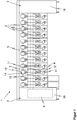
- FIG. 1 shows a schematic view of a spinning machine 1, which is formed according to the present example as a rotor spinning machine.
- the spinning machine 1 has a plurality of jobs 3, which in the longitudinal direction of Spinning machine 1 between two front ends 2, in present case in frontal frames 16, are arranged side by side.
- Each of the workstations 3 of the spinning machine 1 has a plurality of working members for yarn production, which in the present case are only designated at a single workstation 3 for reasons of clarity.
- the jobs each have a feeder 11, a spinning element 12, in this case a spinning rotor, and a trigger 13 for deduction of the finished spun yarn, which is wound by means of a winding device 14 on a spool 15 in a conventional manner.
- a rotor spinning machine is shown, in the case of a ring spinning machine or an air jet spinning machine, however, are also feeders 11 in the form of a drafting system, spinning elements 12 in the form of an air nozzle or ring spindle, and take-off devices 13 and winding devices 14 available.
- each of the workstations 3 has at least one suction point 4.
- the extraction point 4 is located in the area of the spinning element 12 designed as a spinning rotor in order to provide the spinning vacuum in the rotor housing in a manner known per se.
- the extraction point 4 could be, for example, in the region of a drafting device outlet or else in the region of the spinning element or the air nozzle.
- further extraction points 4 are conceivable, for example, in areas to be particularly cleaned.
- the suction points 4 are connected via a suction line 17 with a central suction channel 5, which in the present case extends over the entire length of the spinning machine 1 and is acted upon via a central, in this case arranged in one of the two frames 16, suction device 6.
- the suction device 6 includes at least one fan 8 (see Fig. 2 ).
- the suction device 6 may also include a plurality of fans 8, which are both arranged in the same frame 16 or in can be arranged 16 further frames.
- the suction device 6 may also include a plurality of fans 8, which are both arranged in the same frame 16 or in can be arranged 16 further frames.
- numerous modifications are possible. It could also be provided between the workstations 3 more frames 16 or more fans 8 may be arranged in other racks 16, which may be arranged both at one or both of the ends 2 of the spinning machine 1 and in a central region of the spinning machine 1 between the two
- the suction device 6 or the at least one fan 8 of the suction device 6 also need not necessarily be arranged in one of the frontal frames 16, but could also be accommodated elsewhere.
- one or more fans 8 without frame 16 above or below the workstations 3 can be arranged to save space.
- several suction channels 15 may be present, which each extend only over part lengths of the spinning machine 1. In the present case, for the sake of clarity, only a few workstations 3 are arranged in the spinning machine 1. In real spinning machines 1, however, 170 or more jobs 3 are arranged in total.
- a suction device 6 with at least two different action areas 7a, 7b is provided.
- FIG. 2 shows a first embodiment of such a suction device 6, in which an effective area 7a is provided with an axial flow direction in the form of an axial fan 8a, and a second effective area 7b with radial flow direction in the form of a centrifugal fan 8b.
- the axial fan 8a and the radial fan 8b are arranged one behind the other in the flow direction SR of the medium flowing through the suction device 6, which flows from the suction side SS to the pressure side DS.
- the axial fan 8a and the radial fan 8b are arranged on a common axis 18 and are through a common drive 19 driven.
- inlet nozzles 20 can be connected upstream in a conventional manner. Furthermore, even if this is not shown here, one or more tail units can be arranged in particular after the axial fan 8a.
- the suction device 6 is now connected on its suction side SS to the suction channel 5 of the spinning machine 1, so that the air to be sucked there via the inlet nozzle 20 and the axial fan 8a enters the suction device 6 and 8b passes from this into the centrifugal fan, they in the usual Way in the radial direction on the pressure side DS of the suction device 6 leaves.
- the radial fan 8b is preferably provided with a spiral housing 21, which contributes to the increase of the pressure and thus to the efficiency of the fan 8b.
- FIG. 3 shows another embodiment of a fan 8, of which only the impeller 9 is shown. Shown is a plan view of the suction side SS of the impeller 9.
- the impeller 9 shown here has two different impeller blades 10a, 10b.
- first impeller blades 10a are designed such that they have an area of action with an axial flow direction 7a in the manner of an axial fan 8a.
- second impeller blades 10b are arranged, which have a region of action 7b in the manner of a radial fan 8b with a radial flow direction.
- the impeller blades 10a are preferably arranged such that the medium flowing on the suction side SS first passes only in the area of action 7a with axial flow direction and then from the impeller blades 10a only in the axially slightly behind the impeller blades 10a arranged effective area 7b with radial flow direction second impeller blades 10b passes.
- FIG. 4 finally shows a schematic view of a fan 8, which has an impeller 9 with specially shaped impeller blades 10c.
- the impeller blade 10c includes both an effective region 7a with an axial flow direction and an effective region 7b with a radial flow direction.
- the impeller blade 10c is curved in such a three-dimensional manner that the two effective regions 7a, 7b merge substantially continuously into one another.
- the medium flowing through the fan 8 is sucked in on the suction side SS, as symbolized by corresponding arrows, and initially strikes the effective region 7a with an axial flow direction, from where it is forwarded into the effective region 7b with a radial flow direction. There, the first medium flowing axially into the fan 8 medium is deflected in the radial direction and guided radially outward until it again leaves the fan 8 in the radial direction, as symbolized by the arrows on the pressure side DS.
Landscapes
- Engineering & Computer Science (AREA)
- Mechanical Engineering (AREA)
- Textile Engineering (AREA)
- Spinning Or Twisting Of Yarns (AREA)
- Structures Of Non-Positive Displacement Pumps (AREA)
- Ventilation (AREA)
- Duct Arrangements (AREA)
- Spinning Methods And Devices For Manufacturing Artificial Fibers (AREA)
Applications Claiming Priority (1)
| Application Number | Priority Date | Filing Date | Title |
|---|---|---|---|
| DE102016101653.5A DE102016101653B4 (de) | 2016-01-29 | 2016-01-29 | Spinnmaschine mit Absaugeinrichtung |
Publications (2)
| Publication Number | Publication Date |
|---|---|
| EP3199675A1 true EP3199675A1 (fr) | 2017-08-02 |
| EP3199675B1 EP3199675B1 (fr) | 2023-03-29 |
Family
ID=57838283
Family Applications (1)
| Application Number | Title | Priority Date | Filing Date |
|---|---|---|---|
| EP17151981.2A Active EP3199675B1 (fr) | 2016-01-29 | 2017-01-18 | Métier à filer comprenant un dispositif d'aspiration |
Country Status (4)
| Country | Link |
|---|---|
| EP (1) | EP3199675B1 (fr) |
| JP (1) | JP2017179687A (fr) |
| CN (1) | CN107119359B (fr) |
| DE (1) | DE102016101653B4 (fr) |
Cited By (1)
| Publication number | Priority date | Publication date | Assignee | Title |
|---|---|---|---|---|
| CN108193334A (zh) * | 2018-03-28 | 2018-06-22 | 湖北天门纺织机械股份有限公司 | 一种环锭细纱机新型吸棉装置 |
Citations (9)
| Publication number | Priority date | Publication date | Assignee | Title |
|---|---|---|---|---|
| DE950772C (de) * | 1953-05-03 | 1956-10-18 | Lufttechnische Ges M B H | Fadenbruch-Absauganlage fuer Spinnmaschinen |
| US4622713A (en) * | 1982-09-13 | 1986-11-18 | Murata Kikai Kabushi Kaisha | Fly removing system in textile machine |
| JPH0932796A (ja) * | 1995-07-18 | 1997-02-04 | Toshiba Corp | 送風機 |
| DE102004016796A1 (de) * | 2004-04-06 | 2005-10-27 | Rieter Ingolstadt Spinnereimaschinenbau Ag | Spinnmaschine und Verfahren zu deren Betrieb |
| DE102006029056A1 (de) | 2006-06-24 | 2007-12-27 | Oerlikon Textile Gmbh & Co. Kg | Spinnmaschine |
| DE102006035729A1 (de) | 2006-07-28 | 2008-01-31 | Maschinenfabrik Rieter Ag | Vorrichtung und Verfahren zum Absaugen und Filtern von staub- und/oder faserbelasteter Luft an Textilmaschinen |
| EP1950162A2 (fr) * | 2007-01-29 | 2008-07-30 | SAVIO MACCHINE TESSILI S.p.A. | Système d'aspiration pour bobinoir |
| US20090324411A1 (en) * | 2008-06-26 | 2009-12-31 | Stanley Gavin D | Blower fan for low profile environment |
| EP2626453A1 (fr) * | 2010-10-05 | 2013-08-14 | Murata Machinery, Ltd. | Dispositif d'aspiration et de séparation et machine textile équipée d'un tel dispositif |
Family Cites Families (2)
| Publication number | Priority date | Publication date | Assignee | Title |
|---|---|---|---|---|
| DE3708382A1 (de) * | 1987-03-14 | 1988-09-22 | Schlafhorst & Co W | Textilmaschine mit einem radialventilator |
| CN201582198U (zh) * | 2009-12-22 | 2010-09-15 | 江阴市宏达风机有限公司 | 气流纺机工艺用离心风机 |
-
2016
- 2016-01-29 DE DE102016101653.5A patent/DE102016101653B4/de not_active Expired - Fee Related
-
2017
- 2017-01-10 CN CN201710017240.6A patent/CN107119359B/zh active Active
- 2017-01-18 EP EP17151981.2A patent/EP3199675B1/fr active Active
- 2017-01-26 JP JP2017012285A patent/JP2017179687A/ja active Pending
Patent Citations (9)
| Publication number | Priority date | Publication date | Assignee | Title |
|---|---|---|---|---|
| DE950772C (de) * | 1953-05-03 | 1956-10-18 | Lufttechnische Ges M B H | Fadenbruch-Absauganlage fuer Spinnmaschinen |
| US4622713A (en) * | 1982-09-13 | 1986-11-18 | Murata Kikai Kabushi Kaisha | Fly removing system in textile machine |
| JPH0932796A (ja) * | 1995-07-18 | 1997-02-04 | Toshiba Corp | 送風機 |
| DE102004016796A1 (de) * | 2004-04-06 | 2005-10-27 | Rieter Ingolstadt Spinnereimaschinenbau Ag | Spinnmaschine und Verfahren zu deren Betrieb |
| DE102006029056A1 (de) | 2006-06-24 | 2007-12-27 | Oerlikon Textile Gmbh & Co. Kg | Spinnmaschine |
| DE102006035729A1 (de) | 2006-07-28 | 2008-01-31 | Maschinenfabrik Rieter Ag | Vorrichtung und Verfahren zum Absaugen und Filtern von staub- und/oder faserbelasteter Luft an Textilmaschinen |
| EP1950162A2 (fr) * | 2007-01-29 | 2008-07-30 | SAVIO MACCHINE TESSILI S.p.A. | Système d'aspiration pour bobinoir |
| US20090324411A1 (en) * | 2008-06-26 | 2009-12-31 | Stanley Gavin D | Blower fan for low profile environment |
| EP2626453A1 (fr) * | 2010-10-05 | 2013-08-14 | Murata Machinery, Ltd. | Dispositif d'aspiration et de séparation et machine textile équipée d'un tel dispositif |
Cited By (2)
| Publication number | Priority date | Publication date | Assignee | Title |
|---|---|---|---|---|
| CN108193334A (zh) * | 2018-03-28 | 2018-06-22 | 湖北天门纺织机械股份有限公司 | 一种环锭细纱机新型吸棉装置 |
| CN108193334B (zh) * | 2018-03-28 | 2023-11-21 | 湖北天门纺织机械股份有限公司 | 一种环锭细纱机新型吸棉装置 |
Also Published As
| Publication number | Publication date |
|---|---|
| CN107119359B (zh) | 2022-03-15 |
| DE102016101653A1 (de) | 2017-08-03 |
| CN107119359A (zh) | 2017-09-01 |
| JP2017179687A (ja) | 2017-10-05 |
| EP3199675B1 (fr) | 2023-03-29 |
| DE102016101653B4 (de) | 2023-01-12 |
Similar Documents
| Publication | Publication Date | Title |
|---|---|---|
| EP1845180B1 (fr) | Composant en forme de broche pour dispositif de filage à jet d'air doté d'un canal d'injection | |
| EP3237658B1 (fr) | Métier à filer à rotor comportant une pluralité d'emplacements de travail et un dispositif d'aspiration | |
| EP2895646B1 (fr) | Poste de filage d'un métier à filer à jet d'air | |
| EP2511403B1 (fr) | Banc à broches pour la fabrication d'une mèche | |
| EP2895647B1 (fr) | Poste de filage d'un banc à broches | |
| DE102016110147A1 (de) | Spinnmaschine mit einer Vielzahl von Arbeitsstellen und einer Absaugeinrichtung | |
| DE3611824A1 (de) | Verfahren und anlage zum betreiben von fadenbruch- und/oder luntenbruch-absaugkanaelen | |
| EP1786961A1 (fr) | Dispositif de filature a jet d'air | |
| EP3449048A1 (fr) | Métier à filer à jet d'air et procédé de production d'un fil | |
| DE102008006379A1 (de) | Luftspinnvorrichtung | |
| DE102016119237A1 (de) | Luftspinnmaschine | |
| DE10311826A1 (de) | Vorrichtung zum Herstellen eines gesponnenen Fadens | |
| CH674855A5 (fr) | ||
| EP3199675B1 (fr) | Métier à filer comprenant un dispositif d'aspiration | |
| EP3604646B1 (fr) | Unité de banc d'étirage | |
| EP0143119B1 (fr) | Dispositif coupe-fil pour métier à tisser, plus particulièrement pour les métiers à tisser à foule linéaire multiple | |
| DE102006047120A1 (de) | Luftdüsenaggregat zum Herstellen eines gesponnenen Garnes | |
| EP2986765B1 (fr) | Banc d'étirage pour machine à tricoter | |
| DE102005022686A1 (de) | Vorrichtung zum Herstellen eines gesponnenen Fadens | |
| WO2005061765A1 (fr) | Dispositif pour filer un fil a partir d'une meche de fibres discontinues | |
| EP3688209B1 (fr) | Dispositif condenseur | |
| EP0311946A1 (fr) | Procédé et dispositif pour enlever des fibres d'un cylindre peigneur d'une unité de filage d'un métier à filer à bout libre | |
| DE102020101840A1 (de) | Fadenführungseinheit, Offenend-Rotorspinnmaschine und Verfahren zum Betreiben einer Spinnstelle | |
| WO2004059052A1 (fr) | Boitier de filieres destine a un dispositif de filieres a air | |
| DE848022C (de) | Absauganlage fuer Spinnmaschinen zum Abfuehren gerissener Faeden |
Legal Events
| Date | Code | Title | Description |
|---|---|---|---|
| PUAI | Public reference made under article 153(3) epc to a published international application that has entered the european phase |
Free format text: ORIGINAL CODE: 0009012 |
|
| STAA | Information on the status of an ep patent application or granted ep patent |
Free format text: STATUS: THE APPLICATION HAS BEEN PUBLISHED |
|
| AK | Designated contracting states |
Kind code of ref document: A1 Designated state(s): AL AT BE BG CH CY CZ DE DK EE ES FI FR GB GR HR HU IE IS IT LI LT LU LV MC MK MT NL NO PL PT RO RS SE SI SK SM TR |
|
| AX | Request for extension of the european patent |
Extension state: BA ME |
|
| STAA | Information on the status of an ep patent application or granted ep patent |
Free format text: STATUS: REQUEST FOR EXAMINATION WAS MADE |
|
| 17P | Request for examination filed |
Effective date: 20180126 |
|
| RBV | Designated contracting states (corrected) |
Designated state(s): AL AT BE BG CH CY CZ DE DK EE ES FI FR GB GR HR HU IE IS IT LI LT LU LV MC MK MT NL NO PL PT RO RS SE SI SK SM TR |
|
| STAA | Information on the status of an ep patent application or granted ep patent |
Free format text: STATUS: EXAMINATION IS IN PROGRESS |
|
| 17Q | First examination report despatched |
Effective date: 20200703 |
|
| RAP3 | Party data changed (applicant data changed or rights of an application transferred) |
Owner name: RIETER INGOLSTADT GMBH |
|
| GRAP | Despatch of communication of intention to grant a patent |
Free format text: ORIGINAL CODE: EPIDOSNIGR1 |
|
| STAA | Information on the status of an ep patent application or granted ep patent |
Free format text: STATUS: GRANT OF PATENT IS INTENDED |
|
| INTG | Intention to grant announced |
Effective date: 20221102 |
|
| GRAS | Grant fee paid |
Free format text: ORIGINAL CODE: EPIDOSNIGR3 |
|
| GRAA | (expected) grant |
Free format text: ORIGINAL CODE: 0009210 |
|
| STAA | Information on the status of an ep patent application or granted ep patent |
Free format text: STATUS: THE PATENT HAS BEEN GRANTED |
|
| AK | Designated contracting states |
Kind code of ref document: B1 Designated state(s): AL AT BE BG CH CY CZ DE DK EE ES FI FR GB GR HR HU IE IS IT LI LT LU LV MC MK MT NL NO PL PT RO RS SE SI SK SM TR |
|
| REG | Reference to a national code |
Ref country code: GB Ref legal event code: FG4D Free format text: NOT ENGLISH |
|
| REG | Reference to a national code |
Ref country code: CH Ref legal event code: EP |
|
| REG | Reference to a national code |
Ref country code: DE Ref legal event code: R096 Ref document number: 502017014545 Country of ref document: DE |
|
| REG | Reference to a national code |
Ref country code: AT Ref legal event code: REF Ref document number: 1556718 Country of ref document: AT Kind code of ref document: T Effective date: 20230415 |
|
| REG | Reference to a national code |
Ref country code: IE Ref legal event code: FG4D Free format text: LANGUAGE OF EP DOCUMENT: GERMAN |
|
| P01 | Opt-out of the competence of the unified patent court (upc) registered |
Effective date: 20230329 |
|
| REG | Reference to a national code |
Ref country code: LT Ref legal event code: MG9D |
|
| PG25 | Lapsed in a contracting state [announced via postgrant information from national office to epo] |
Ref country code: RS Free format text: LAPSE BECAUSE OF FAILURE TO SUBMIT A TRANSLATION OF THE DESCRIPTION OR TO PAY THE FEE WITHIN THE PRESCRIBED TIME-LIMIT Effective date: 20230329 Ref country code: NO Free format text: LAPSE BECAUSE OF FAILURE TO SUBMIT A TRANSLATION OF THE DESCRIPTION OR TO PAY THE FEE WITHIN THE PRESCRIBED TIME-LIMIT Effective date: 20230629 Ref country code: LV Free format text: LAPSE BECAUSE OF FAILURE TO SUBMIT A TRANSLATION OF THE DESCRIPTION OR TO PAY THE FEE WITHIN THE PRESCRIBED TIME-LIMIT Effective date: 20230329 Ref country code: LT Free format text: LAPSE BECAUSE OF FAILURE TO SUBMIT A TRANSLATION OF THE DESCRIPTION OR TO PAY THE FEE WITHIN THE PRESCRIBED TIME-LIMIT Effective date: 20230329 Ref country code: HR Free format text: LAPSE BECAUSE OF FAILURE TO SUBMIT A TRANSLATION OF THE DESCRIPTION OR TO PAY THE FEE WITHIN THE PRESCRIBED TIME-LIMIT Effective date: 20230329 |
|
| REG | Reference to a national code |
Ref country code: NL Ref legal event code: MP Effective date: 20230329 |
|
| PG25 | Lapsed in a contracting state [announced via postgrant information from national office to epo] |
Ref country code: SE Free format text: LAPSE BECAUSE OF FAILURE TO SUBMIT A TRANSLATION OF THE DESCRIPTION OR TO PAY THE FEE WITHIN THE PRESCRIBED TIME-LIMIT Effective date: 20230329 Ref country code: NL Free format text: LAPSE BECAUSE OF FAILURE TO SUBMIT A TRANSLATION OF THE DESCRIPTION OR TO PAY THE FEE WITHIN THE PRESCRIBED TIME-LIMIT Effective date: 20230329 Ref country code: GR Free format text: LAPSE BECAUSE OF FAILURE TO SUBMIT A TRANSLATION OF THE DESCRIPTION OR TO PAY THE FEE WITHIN THE PRESCRIBED TIME-LIMIT Effective date: 20230630 Ref country code: FI Free format text: LAPSE BECAUSE OF FAILURE TO SUBMIT A TRANSLATION OF THE DESCRIPTION OR TO PAY THE FEE WITHIN THE PRESCRIBED TIME-LIMIT Effective date: 20230329 |
|
| PG25 | Lapsed in a contracting state [announced via postgrant information from national office to epo] |
Ref country code: SM Free format text: LAPSE BECAUSE OF FAILURE TO SUBMIT A TRANSLATION OF THE DESCRIPTION OR TO PAY THE FEE WITHIN THE PRESCRIBED TIME-LIMIT Effective date: 20230329 Ref country code: RO Free format text: LAPSE BECAUSE OF FAILURE TO SUBMIT A TRANSLATION OF THE DESCRIPTION OR TO PAY THE FEE WITHIN THE PRESCRIBED TIME-LIMIT Effective date: 20230329 Ref country code: PT Free format text: LAPSE BECAUSE OF FAILURE TO SUBMIT A TRANSLATION OF THE DESCRIPTION OR TO PAY THE FEE WITHIN THE PRESCRIBED TIME-LIMIT Effective date: 20230731 Ref country code: ES Free format text: LAPSE BECAUSE OF FAILURE TO SUBMIT A TRANSLATION OF THE DESCRIPTION OR TO PAY THE FEE WITHIN THE PRESCRIBED TIME-LIMIT Effective date: 20230329 Ref country code: EE Free format text: LAPSE BECAUSE OF FAILURE TO SUBMIT A TRANSLATION OF THE DESCRIPTION OR TO PAY THE FEE WITHIN THE PRESCRIBED TIME-LIMIT Effective date: 20230329 |
|
| PG25 | Lapsed in a contracting state [announced via postgrant information from national office to epo] |
Ref country code: SK Free format text: LAPSE BECAUSE OF FAILURE TO SUBMIT A TRANSLATION OF THE DESCRIPTION OR TO PAY THE FEE WITHIN THE PRESCRIBED TIME-LIMIT Effective date: 20230329 Ref country code: PL Free format text: LAPSE BECAUSE OF FAILURE TO SUBMIT A TRANSLATION OF THE DESCRIPTION OR TO PAY THE FEE WITHIN THE PRESCRIBED TIME-LIMIT Effective date: 20230329 Ref country code: IS Free format text: LAPSE BECAUSE OF FAILURE TO SUBMIT A TRANSLATION OF THE DESCRIPTION OR TO PAY THE FEE WITHIN THE PRESCRIBED TIME-LIMIT Effective date: 20230729 |
|
| REG | Reference to a national code |
Ref country code: DE Ref legal event code: R097 Ref document number: 502017014545 Country of ref document: DE |
|
| PG25 | Lapsed in a contracting state [announced via postgrant information from national office to epo] |
Ref country code: DK Free format text: LAPSE BECAUSE OF FAILURE TO SUBMIT A TRANSLATION OF THE DESCRIPTION OR TO PAY THE FEE WITHIN THE PRESCRIBED TIME-LIMIT Effective date: 20230329 Ref country code: CZ Free format text: LAPSE BECAUSE OF FAILURE TO SUBMIT A TRANSLATION OF THE DESCRIPTION OR TO PAY THE FEE WITHIN THE PRESCRIBED TIME-LIMIT Effective date: 20230329 |
|
| PLBE | No opposition filed within time limit |
Free format text: ORIGINAL CODE: 0009261 |
|
| STAA | Information on the status of an ep patent application or granted ep patent |
Free format text: STATUS: NO OPPOSITION FILED WITHIN TIME LIMIT |
|
| 26N | No opposition filed |
Effective date: 20240103 |
|
| PG25 | Lapsed in a contracting state [announced via postgrant information from national office to epo] |
Ref country code: SI Free format text: LAPSE BECAUSE OF FAILURE TO SUBMIT A TRANSLATION OF THE DESCRIPTION OR TO PAY THE FEE WITHIN THE PRESCRIBED TIME-LIMIT Effective date: 20230329 |
|
| PG25 | Lapsed in a contracting state [announced via postgrant information from national office to epo] |
Ref country code: SI Free format text: LAPSE BECAUSE OF FAILURE TO SUBMIT A TRANSLATION OF THE DESCRIPTION OR TO PAY THE FEE WITHIN THE PRESCRIBED TIME-LIMIT Effective date: 20230329 |
|
| PG25 | Lapsed in a contracting state [announced via postgrant information from national office to epo] |
Ref country code: MC Free format text: LAPSE BECAUSE OF FAILURE TO SUBMIT A TRANSLATION OF THE DESCRIPTION OR TO PAY THE FEE WITHIN THE PRESCRIBED TIME-LIMIT Effective date: 20230329 |
|
| PG25 | Lapsed in a contracting state [announced via postgrant information from national office to epo] |
Ref country code: MC Free format text: LAPSE BECAUSE OF FAILURE TO SUBMIT A TRANSLATION OF THE DESCRIPTION OR TO PAY THE FEE WITHIN THE PRESCRIBED TIME-LIMIT Effective date: 20230329 |
|
| REG | Reference to a national code |
Ref country code: CH Ref legal event code: PL |
|
| PG25 | Lapsed in a contracting state [announced via postgrant information from national office to epo] |
Ref country code: LU Free format text: LAPSE BECAUSE OF NON-PAYMENT OF DUE FEES Effective date: 20240118 |
|
| GBPC | Gb: european patent ceased through non-payment of renewal fee |
Effective date: 20240118 |
|
| PG25 | Lapsed in a contracting state [announced via postgrant information from national office to epo] |
Ref country code: LU Free format text: LAPSE BECAUSE OF NON-PAYMENT OF DUE FEES Effective date: 20240118 |
|
| PG25 | Lapsed in a contracting state [announced via postgrant information from national office to epo] |
Ref country code: GB Free format text: LAPSE BECAUSE OF NON-PAYMENT OF DUE FEES Effective date: 20240118 |
|
| PG25 | Lapsed in a contracting state [announced via postgrant information from national office to epo] |
Ref country code: BE Free format text: LAPSE BECAUSE OF NON-PAYMENT OF DUE FEES Effective date: 20240131 |
|
| PG25 | Lapsed in a contracting state [announced via postgrant information from national office to epo] |
Ref country code: FR Free format text: LAPSE BECAUSE OF NON-PAYMENT OF DUE FEES Effective date: 20240131 |
|
| PG25 | Lapsed in a contracting state [announced via postgrant information from national office to epo] |
Ref country code: CH Free format text: LAPSE BECAUSE OF NON-PAYMENT OF DUE FEES Effective date: 20240131 |
|
| PG25 | Lapsed in a contracting state [announced via postgrant information from national office to epo] |
Ref country code: GB Free format text: LAPSE BECAUSE OF NON-PAYMENT OF DUE FEES Effective date: 20240118 Ref country code: FR Free format text: LAPSE BECAUSE OF NON-PAYMENT OF DUE FEES Effective date: 20240131 Ref country code: CH Free format text: LAPSE BECAUSE OF NON-PAYMENT OF DUE FEES Effective date: 20240131 Ref country code: BE Free format text: LAPSE BECAUSE OF NON-PAYMENT OF DUE FEES Effective date: 20240131 |
|
| REG | Reference to a national code |
Ref country code: BE Ref legal event code: MM Effective date: 20240131 |
|
| PG25 | Lapsed in a contracting state [announced via postgrant information from national office to epo] |
Ref country code: BG Free format text: LAPSE BECAUSE OF FAILURE TO SUBMIT A TRANSLATION OF THE DESCRIPTION OR TO PAY THE FEE WITHIN THE PRESCRIBED TIME-LIMIT Effective date: 20230329 |
|
| PG25 | Lapsed in a contracting state [announced via postgrant information from national office to epo] |
Ref country code: BG Free format text: LAPSE BECAUSE OF FAILURE TO SUBMIT A TRANSLATION OF THE DESCRIPTION OR TO PAY THE FEE WITHIN THE PRESCRIBED TIME-LIMIT Effective date: 20230329 |
|
| REG | Reference to a national code |
Ref country code: DE Ref legal event code: R081 Ref document number: 502017014545 Country of ref document: DE Owner name: SPINDELFABRIK SUESSEN GMBH, DE Free format text: FORMER OWNER: RIETER INGOLSTADT GMBH, 85055 INGOLSTADT, DE |
|
| PG25 | Lapsed in a contracting state [announced via postgrant information from national office to epo] |
Ref country code: IE Free format text: LAPSE BECAUSE OF NON-PAYMENT OF DUE FEES Effective date: 20240118 |
|
| PG25 | Lapsed in a contracting state [announced via postgrant information from national office to epo] |
Ref country code: IE Free format text: LAPSE BECAUSE OF NON-PAYMENT OF DUE FEES Effective date: 20240118 |
|
| REG | Reference to a national code |
Ref country code: AT Ref legal event code: MM01 Ref document number: 1556718 Country of ref document: AT Kind code of ref document: T Effective date: 20240118 |
|
| PG25 | Lapsed in a contracting state [announced via postgrant information from national office to epo] |
Ref country code: AT Free format text: LAPSE BECAUSE OF NON-PAYMENT OF DUE FEES Effective date: 20240118 |
|
| PGFP | Annual fee paid to national office [announced via postgrant information from national office to epo] |
Ref country code: IT Payment date: 20250129 Year of fee payment: 9 |
|
| PG25 | Lapsed in a contracting state [announced via postgrant information from national office to epo] |
Ref country code: CY Free format text: LAPSE BECAUSE OF FAILURE TO SUBMIT A TRANSLATION OF THE DESCRIPTION OR TO PAY THE FEE WITHIN THE PRESCRIBED TIME-LIMIT; INVALID AB INITIO Effective date: 20170118 |
|
| PG25 | Lapsed in a contracting state [announced via postgrant information from national office to epo] |
Ref country code: HU Free format text: LAPSE BECAUSE OF FAILURE TO SUBMIT A TRANSLATION OF THE DESCRIPTION OR TO PAY THE FEE WITHIN THE PRESCRIBED TIME-LIMIT; INVALID AB INITIO Effective date: 20170118 |
|
| PGFP | Annual fee paid to national office [announced via postgrant information from national office to epo] |
Ref country code: DE Payment date: 20260203 Year of fee payment: 10 |