EP3200323B1 - Moteur destiné à être utilisé dans un environnement de réfrigérant - Google Patents
Moteur destiné à être utilisé dans un environnement de réfrigérant Download PDFInfo
- Publication number
- EP3200323B1 EP3200323B1 EP17153201.3A EP17153201A EP3200323B1 EP 3200323 B1 EP3200323 B1 EP 3200323B1 EP 17153201 A EP17153201 A EP 17153201A EP 3200323 B1 EP3200323 B1 EP 3200323B1
- Authority
- EP
- European Patent Office
- Prior art keywords
- stator
- motor
- shell
- accordance
- coils
- Prior art date
- Legal status (The legal status is an assumption and is not a legal conclusion. Google has not performed a legal analysis and makes no representation as to the accuracy of the status listed.)
- Active
Links
Images


Classifications
-
- F—MECHANICAL ENGINEERING; LIGHTING; HEATING; WEAPONS; BLASTING
- F25—REFRIGERATION OR COOLING; COMBINED HEATING AND REFRIGERATION SYSTEMS; HEAT PUMP SYSTEMS; MANUFACTURE OR STORAGE OF ICE; LIQUEFACTION SOLIDIFICATION OF GASES
- F25B—REFRIGERATION MACHINES, PLANTS OR SYSTEMS; COMBINED HEATING AND REFRIGERATION SYSTEMS; HEAT PUMP SYSTEMS
- F25B31/00—Compressor arrangements
- F25B31/02—Compressor arrangements of motor-compressor units
- F25B31/026—Compressor arrangements of motor-compressor units with compressor of rotary type
-
- H—ELECTRICITY
- H02—GENERATION; CONVERSION OR DISTRIBUTION OF ELECTRIC POWER
- H02K—DYNAMO-ELECTRIC MACHINES
- H02K15/00—Processes or apparatus specially adapted for manufacturing, assembling, maintaining or repairing of dynamo-electric machines
- H02K15/02—Processes or apparatus specially adapted for manufacturing, assembling, maintaining or repairing of dynamo-electric machines of stator or rotor bodies
-
- H—ELECTRICITY
- H02—GENERATION; CONVERSION OR DISTRIBUTION OF ELECTRIC POWER
- H02K—DYNAMO-ELECTRIC MACHINES
- H02K15/00—Processes or apparatus specially adapted for manufacturing, assembling, maintaining or repairing of dynamo-electric machines
- H02K15/02—Processes or apparatus specially adapted for manufacturing, assembling, maintaining or repairing of dynamo-electric machines of stator or rotor bodies
- H02K15/021—Magnetic cores
- H02K15/026—Wound cores
-
- H—ELECTRICITY
- H02—GENERATION; CONVERSION OR DISTRIBUTION OF ELECTRIC POWER
- H02K—DYNAMO-ELECTRIC MACHINES
- H02K3/00—Details of windings
- H02K3/04—Windings characterised by the conductor shape, form or construction, e.g. with bar conductors
- H02K3/28—Layout of windings or of connections between windings
-
- H—ELECTRICITY
- H02—GENERATION; CONVERSION OR DISTRIBUTION OF ELECTRIC POWER
- H02K—DYNAMO-ELECTRIC MACHINES
- H02K3/00—Details of windings
- H02K3/30—Windings characterised by the insulating material
-
- H—ELECTRICITY
- H02—GENERATION; CONVERSION OR DISTRIBUTION OF ELECTRIC POWER
- H02K—DYNAMO-ELECTRIC MACHINES
- H02K3/00—Details of windings
- H02K3/44—Protection against moisture or chemical attack; Windings specially adapted for operation in liquid or gas
-
- H—ELECTRICITY
- H02—GENERATION; CONVERSION OR DISTRIBUTION OF ELECTRIC POWER
- H02K—DYNAMO-ELECTRIC MACHINES
- H02K3/00—Details of windings
- H02K3/46—Fastening of windings on the stator or rotor structure
- H02K3/48—Fastening of windings on the stator or rotor structure in slots
- H02K3/487—Slot-closing devices
-
- H—ELECTRICITY
- H02—GENERATION; CONVERSION OR DISTRIBUTION OF ELECTRIC POWER
- H02K—DYNAMO-ELECTRIC MACHINES
- H02K3/00—Details of windings
- H02K3/46—Fastening of windings on the stator or rotor structure
- H02K3/50—Fastening of winding heads, equalising connectors, or connections thereto
Definitions
- the present invention relates to electric motors for use in an ammonia environment. More specifically, the present invention relates to motors for use in an ammonia environment.
- EP 1291528 A2 discloses a scroll compressor and a refrigerating system using an ammonia group refrigerant.
- US 3,688,137 A discloses in a general way electric machines of the open type intended to operate in a fluid medium or in a corrosive atmosphere.
- US 2009/191074 A1 discloses an electrically powered pump that has an electric motor arrangement for driving a pump arrangement.
- a motor for use in a refrigerant atmosphere is defined in claim 1.
- FIG. 1 illustrates a refrigeration system 10 that includes a compressor chamber 15 that contains a compressor 20 driven by an electric motor 25.
- the refrigeration system 10 also includes an evaporator 31, a condenser 32, and an expansion valve 33.
- the refrigeration system 10 is adapted for use with a refrigeration fluid such as ammonia.
- the ammonia is refrigerant grade R-717 ammonia.
- the compressor 20 could include one of a variety of different types of compressors including rotary screw, reciprocating, scroll, centrifugal, and the like.
- the actual style of compressor employed is not critical to the invention. Rather, all that is required is that the compressor 20 includes a stationary portion and a rotary portion coupled to a compressor shaft.
- the motor 25 may be a hermetic motor specifically designed to be submerged within a refrigerant atmosphere.
- the motor 25 can utilize an external power supply that can be line-fed or inverter-fed.
- Motors 25 for ammonia compressors 20 are typically located outside the compressor chamber 15 and use either a shaft seal or a magnetic coupling to connect the motor 25 to the compressor shaft. This has been necessary because of the chemical aggressiveness of refrigerant (e.g., ammonia) towards standard materials of motor construction. Additionally, exposure to high temperature/pressure ammonia causes typical insulation materials to lose their resistance, which in turn causes premature motor failure.
- the present invention constructs the motor 25 out of materials that are more resistant to ammonia and uses techniques and arrangements that enhance the effectiveness of the materials, thereby allowing the motor 25 to be placed in the ammonia environment while operating satisfactorily for a sufficient length of time.
- the motor 25 and the compressor 20 are positioned inside the compressor chamber 15 to save space and provide the motor 25 the benefit of cooling from the refrigerant.
- This cooling of the motor 25 potentially allows for the use of smaller motors to achieve the same performance.
- placing the motor 25 inside the compressor chamber 15 eliminates any potential leakage paths through external shaft seals.
- placing the motor 25 inside the compressor chamber 15 allows for a lower cost unit due to the elimination of duplicate brackets and bearings required to connect the motor externally.
- the compressor shaft can also be made shorter, shaft seals are eliminated, and magnetic couplings are not needed.
- the motor 25 employs a Variable Frequency Drive (VFD) 30 to improve the efficiency of the refrigeration system 10 when compared to more conventional line-fed systems.
- VFD 30 utilizes a control system that is sensitive to motor current draw and system leakage current.
- the motor construction must be modified to assure that there are little or no areas in which the ammonia can make contact with electrically conductive areas within the motor windings or inter-pole connections. Because ammonia has a higher conductivity to electrical current then typical refrigerants used in hermetic compressors and because the motor stator resides in the ammonia, leakage current that might occur will likely be larger than on a motor not disposed in ammonia. Such current leakages would be more likely to cause the VFD motor protection to remove power to the motor 25. To reduce this likelihood, the motor 25 incorporates a stator winding in which no internal connections are present (i.e., each phase winding is continuous). The elimination of internal connections reduces the likelihood of any potential for leakage current to exist due to the ammonia refrigerant.
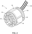
- the motor 25 includes a stator 35 and a rotor 40 disposed adjacent the stator 35 and drivingly connected to the driven shaft of the compressor 20.
- the rotor 40 includes a portion disposed within a cavity 45 of the stator 35.
- other motor arrangements could also be employed to drive the compressor 20.
- the electric motor 25 is positioned within the refrigeration system 10 such that it is directly coupled to the compressor 20 and such that it is directly exposed to the refrigerant, in the illustrated example ammonia. Positioning the motor 25 in this way provides for more efficient transfer of power between the motor 25 and the compressor 20 and also provides more effective cooling of the motor 25 using the refrigerant as a coolant. However, refrigerant can be detrimental to many typical motor components.
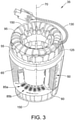
- the stator 35 defines a cavity 45 that receives a portion of the rotor 40.
- the stator 35 includes a core 50 defining opposite end portions 55, 60.
- the stator core 50 includes a plurality of circumferentially spaced stacked metal laminations 65 disposed parallel to a centerline 70 of the cavity 45.
- the metal laminations 65 may consist of electrical grade lamination steel with other materials or constructions such as powdered metal portions being possible.
- the stator core 50 includes a plurality of teeth 75 that each defines a pair of circumferentially spaced longitudinal slot walls 80.
- the slot walls 80 of adjacent teeth 75 cooperate with one another to define longitudinal slots 85 in the periphery of the stator 35.
- Each tooth also defines two hooks 90.
- Circumferentially spaced coils are arranged with each coil disposed on one of the teeth 75 such that each coil is disposed at least partially in two slots 85.
- Each coil consists of a plurality of windings of wire 95 with portions of the windings of wire 95 extending longitudinally in the slots 85 in which the coil resides.
- each coil is defined by a plurality of windings of the wire 95 repeatedly passing through a first slot 85a, around the first end portion 55, passing through a second slot 85b adjacent the first slot 85a, around the second end portion 60, and again through the first slot 85a.
- the wire 95 consists of conductive material 100 immediately surrounded by wire insulation 105.
- copper or aluminum wire 100 is used as the conductor 100 with aluminum being favored in an ammonia environment.
- Polyetheretherketone (PEEK) material may be used to form the insulation 105. While some constructions may use conductors 100 coated with PEEK insulation 105, extruded PEEK insulation 105 may also be used as testing has shown significant performance increases using this construction. Specifically, the extruded PEEK insulation 105 exhibits improved toughness and superior dielectric properties when compared to coated insulation.
- Slot liners 110 are provided in the slots 85 between the windings of wire 95 and the respective slot walls 80 to further insulate the windings 95 from the magnetic core 50.
- the slot liners 110 are formed from sheets of polyphenylene sulfide (PPS). While various thicknesses of slot liners 110 are possible, slot liners 110 that are between about 0.01 and about 0.02 inches (0.25 to 0.5 mm) in thickness may be used in some constructions. The sheet material provides better formability and more robust properties than other materials that were tested.
- the stator 35 may include interphase insulators 115, sometimes referred to as phase paper, between the coils to further insulate the different phases of the motor 25.
- phase paper 15 is employed and is made using sheets of a polyphenylene sulfide (PPS) material similar to that of the slot liners 110. As with the slot liners 110, the sheets provided improved characteristics when compared to other material choices.
- PPS polyphenylene sulfide
- wedges 120 are typically positioned within the slots 85 to take up this space, assure that the individual windings of wire 95 are packed as tightly as possible, and to limit unwanted movement of the wires 95.
- longitudinally extending wedges 120 are employed. Each wedge 120 is positioned between a respective slot liner 110 and the stack of windings 95 within the slot 85. The wedge 120 engages the underside of two adjacent hooks 90 formed as part of the adjacent teeth 75 to apply a compressive force to the wires 95.
- pegs are positioned between the wires 95 and the wedge 120 to take up additional space and to provide a flatter engagement surface for the wedges 120. While many materials are available for wedges 120 and pegs, some constructions may employ wedges 120, and pegs if used, that are formed from one of an epoxide laminate, a polyphenylene sulfide (PPS), and a polyetheretherketone (PEEK) material. The wedges 120 and pegs (if employed) are secured in interlocking relationship with the stator core 50 to prevent radially outward movement of the coils 95 relative to the stator core 50. It should be noted that any combination of the three identified materials could be employed for the construction of the stator 35.
- pegs could be formed from a PEEK material with wedges 120 formed from PPS if desired.
- components could be manufactured as composites.
- pegs or wedges 120 could be formed with a wood core that is coated or covered with extruded PEEK, PPS, or epoxide laminate material.
- the stator 35 includes lacing cord 125 laced about the end turns of the coils.
- the lacing 125 tightly secures the end turns of the coils, thereby reducing unwanted movement or vibration.
- Lacing tape 125 may be formed from a NOMEX ® tape.
- other constructions may use other materials (e.g., KEVLAR ® , other meta-aramids, para-aramids, etc.) for lacing 125.
- the stator 35 also includes lead wire 130 that provides for a connection between the coils and the source of electrical power.
- the lead wire 130 includes conductive material 125 (e.g., copper, aluminum, etc.) immediately surrounded by lead wire insulation 140.
- conductive material 125 e.g., copper, aluminum, etc.
- lead wire insulation 140 e.g., one construction employs conductive material 135 consisting of wound strands of aluminum with lead wire insulation 140 formed from a fluoropolymer such as TEFLON ® (i.e., polytetrafluoroethylene (PTFE)).
- TEFLON ® i.e., polytetrafluoroethylene (PTFE)
- the insulating material is provided in the form of a tape that is wrapped in overlapping relationship about the conductor 135 such that the proportion of tape overlap is at least about 50%.
- the lead wire insulation 140 may include TEFLON ® tape wrapped in overlapping relationship and strands or filaments of fiberglass overbraided over the TEFLON ® tape.
- the fiberglass filaments provide a flexible abrasion-resistant covering over the TEFLON ® tape.
- the motor can be leadless, such that the wire is directly connected to power terminals.
- the stator 35 may also include sleeving 145 which protects the lead wire 130 and further insulates the lead wires 130 from each other at crossovers between the coils.
- the sleeving 145 consists of a fluoropolymer such as TEFLON ® (i.e., polytetrafluoroethylene (PTFE)).
- the shell 150 encapsulates substantially the entire stator 25.
- the shell 150 is free of apertures to reduce the amount of current leakage.
- the shell 150 may be opaque.
- the shell 150 may have any characteristics that enable the motor 25 to operate as described herein.
- the shell 150 includes a low-viscosity epoxy in the form of an amine cured 100% solids epoxy topcoat, such as that available from ARCOR TM Epoxy Technologies, Inc. of South Dennis, MA under the trade name ARCOR TM EE11.
- the shell 150 has an average thickness in a range from about 4 mm to about 10 mm.
- the shell 150 is formed by coating the end turns of the coils and all exposed surfaces of the stator 35 with a liquid that cures to form the shell 150.
- the stator 35 is coated by dipping the stator 35 at least partially in the liquid which adheres to the stator 35 and solidifies to form the shell 150.
- the stator 35 may be coated by trickle application of a liquid that solidifies to form the shell 150.
- the shell 150 may also be formed in any manner that enables the motor 25 to operate as described herein.
- the shell 150 can be used to seal the coils from the ammonia environment, bond the wires 95 together to reduce movement of the wires 95 relative to one another, reduce noise from the motor 25, coat and bond the laminations 65 in the stator 35, and anchor the interphase insulation.
- the shell 150 facilitates protecting the end turns of the coils from nicks or abrasions as the stator 35 is placed in the compressor chamber 15 and during operation of the refrigeration system 10. As a result, the shell 150 increases the resistance of the motor 25 to the ammonia environment and reduces the risk of current leakage from the coils of the stator 35.
- the rotor 40 is formed using conventional materials and techniques.
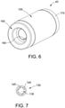
- the rotor 40 illustrated in FIG. 6 includes a rotor core 155 formed from laminations of electrical grade steel or aluminum stacked along the rotational axis 70 to a desired length. In other constructions, portions of the core 155 may be formed from powdered metal or other components.
- Rotor bars 160 extend the length of the core 155 and are coupled to end rings 165, 170 disposed at each end of the core 155. Bars 160 and end rings 165, 170 may be formed using aluminum with other materials being possible.
- the motor 25 formed of the indicated materials is more resistant to attack by ammonia than prior motors.
- the motor 25 can be mounted in the refrigeration system 10 in contact with ammonia, and the refrigeration system 10 is suitable for operation with the motor 25 in contact with ammonia. Therefore, the refrigeration system 10 can be simply and inexpensively constructed without sealing the motor 25 from the ammonia.
Landscapes
- Engineering & Computer Science (AREA)
- Power Engineering (AREA)
- Manufacturing & Machinery (AREA)
- Physics & Mathematics (AREA)
- Mechanical Engineering (AREA)
- Thermal Sciences (AREA)
- General Engineering & Computer Science (AREA)
- Insulation, Fastening Of Motor, Generator Windings (AREA)
Claims (14)
- Moteur (25) destiné à une utilisation dans une atmosphère de réfrigérant, le moteur comprenant :un rotor (40) configuré pour tourner autour d'un axe ;un stator (35) adjacent audit rotor et incluant une surface définissant une cavité (45) configurée pour recevoir au moins une partie dudit rotor, ledit stator comprenant :un noyau (50) définissant une extrémité ;une pluralité de dents (75) définissant une pluralité de fentes (80) ;une pluralité de garnitures de fente (110) positionnées au sein de la pluralité de fentes (80) et formées de polysulfure de phénylène ; etune pluralité de bobines enveloppées autour de ladite pluralité de dents de telle sorte que chaque bobine de ladite pluralité de bobines comprend une paire de parties de fente (85) et une paire de spires d'extrémité, ladite paire de parties de fente s'étendant au moins partiellement à travers des fentes adjacentes de la pluralité de fentes et au moins partiellement à travers ladite pluralité de garnitures de fente (110), chacune desdites spires d'extrémité s'étendant entre ladite paire de parties de fente et au moins partiellement en travers de ladite extrémité ; etune coque (150) encapsulant ledit stator de telle sorte que lesdites spires d'extrémité de ladite pluralité de bobines et la surface sont sensiblement isolées de l'atmosphère de réfrigérant, dans lequel ladite coque est formée par revêtement desdites spires d'extrémité et de ladite surface au moins partiellement avec un liquide qui adhère audit stator et durcit pour former ladite coque, dans lequel ledit stator est sensiblement entièrement encapsulé par ladite coque, et dans lequel ladite coque est sensiblement exempte d'ouvertures pour réduire la fuite de courant depuis ledit stator, et dans lequel ladite coque a une épaisseur moyenne dans une plage d'environ 4 millimètres (mm) à environ 10 mm, et la coque inclut en outre une couche de finition époxy 100 % solide durcie à l'amine.
- Moteur selon la revendication 1, dans lequel ladite coque est opaque.
- Moteur selon la revendication 1, dans lequel le stator inclut en outre un fil conducteur qui assure une connexion entre la pluralité de bobines et une source de puissance électrique, le fil conducteur étant entouré par une isolation de fil conducteur formée de fluoropolymère.
- Moteur selon la revendication 1, dans lequel le stator inclut en outre un cordon de laçage (125) lacé autour des spires d'extrémité de la pluralité de bobines.
- Moteur selon la revendication 1, dans lequel le stator comprend en outre une pluralité d'isolants interphase (115) positionnés entre la pluralité de bobines pour isoler davantage différentes phases du moteur.
- Moteur selon la revendication 1, dans lequel le stator comprend en outre une pluralité de coins positionnés au sein de la pluralité de fentes.
- Moteur selon la revendication 1 ou la revendication 6, dans lequel le stator comprend une pluralité de chevilles positionnées au sein de la pluralité de fentes.
- Moteur selon l'une quelconque des revendications 5, 6 ou 7, dans lequel la pluralité d'isolants interphase, la pluralité de coins ou la pluralité de chevilles sont formés de polysulfure de phénylène.
- Procédé d'assemblage d'un moteur (25) destiné à une utilisation dans une atmosphère de réfrigérant, le procédé comprenant :la formation d'un stator (35) incluant une surface définissant une cavité (45) configurée pour recevoir au moins une partie d'un rotor (40), un noyau (50), et une pluralité de dents (75) définissant une pluralité de fentes, le noyau définissant une extrémité du stator ;le positionnement d'une pluralité de garnitures de fente (110) dans la pluralité de fentes, la pluralité de garnitures de fente (110) étant formée de polysulfure de phénylène ;l'enveloppement d'une pluralité de bobines autour de la pluralité de dents de telle sorte que des spires d'extrémité de la pluralité de bobines s'étendent en travers de l'extrémité ; etla formation d'une coque (150) sur le stator par revêtement des spires d'extrémité et de la surface au moins partiellement avec un liquide qui adhère au stator et durcit pour former la coque de telle sorte que les spires d'extrémité de la pluralité de bobines et l'extrémité du stator et la surface sont sensiblement isolées de l'atmosphère de réfrigérant, dans lequel le stator est sensiblement entièrement encapsulé par la coque, et dans lequel la coque est sensiblement exempte d'ouvertures pour réduire la fuite de courant depuis le stator, et dans lequel ladite coque a une épaisseur moyenne dans une plage d'environ 4 millimètres (mm) à environ 10 mm, et la coque inclut en outre une couche de finition époxy 100 % solide durcie à l'amine.
- Procédé selon la revendication 9, dans lequel la formation du stator comprend l'empilement d'une pluralité de strates pour former un empilement, la coque s'étendant au moins partiellement sur l'empilement.
- Procédé selon la revendication 9, dans lequel la formation de la coque comprend le revêtement de l'extrémité du stator avec un mélange liquide et le fait de laisser le mélange liquide se solidifier au moins partiellement.
- Procédé selon la revendication 11, dans lequel le revêtement de l'extrémité comprend le positionnement de l'extrémité dans un bassin du mélange liquide.
- Système de réfrigération comprenant :une chambre de compresseur configurée pour contenir un réfrigérant ;un compresseur disposé dans la chambre de compresseur et configuré pour aspirer du réfrigérant à une pression à partir de la chambre de compresseur et décharger le réfrigérant à une pression plus élevée ; etle moteur selon l'une quelconque des revendications 1 à 8 disposé au sein de la chambre de compresseur et couplé au compresseur pour entraîner le compresseur.
- Système de réfrigérant selon la revendication 13, dans lequel le système de réfrigérant est adapté pour être utilisé avec de l'ammoniac.
Applications Claiming Priority (2)
| Application Number | Priority Date | Filing Date | Title |
|---|---|---|---|
| CN201610055583.7A CN107017722B (zh) | 2016-01-27 | 2016-01-27 | 在制冷剂环境中使用的马达 |
| US15/049,937 US10670310B2 (en) | 2013-01-28 | 2016-02-22 | Motor for use in refrigerant environment |
Publications (2)
| Publication Number | Publication Date |
|---|---|
| EP3200323A1 EP3200323A1 (fr) | 2017-08-02 |
| EP3200323B1 true EP3200323B1 (fr) | 2022-03-16 |
Family
ID=57906524
Family Applications (1)
| Application Number | Title | Priority Date | Filing Date |
|---|---|---|---|
| EP17153201.3A Active EP3200323B1 (fr) | 2016-01-27 | 2017-01-26 | Moteur destiné à être utilisé dans un environnement de réfrigérant |
Country Status (4)
| Country | Link |
|---|---|
| US (1) | US10670310B2 (fr) |
| EP (1) | EP3200323B1 (fr) |
| DK (1) | DK3200323T3 (fr) |
| ES (1) | ES2910078T3 (fr) |
Families Citing this family (5)
| Publication number | Priority date | Publication date | Assignee | Title |
|---|---|---|---|---|
| CN110168877B (zh) * | 2016-12-23 | 2021-08-10 | 维斯塔斯风力系统集团公司 | 电机定子的电隔离安装 |
| FR3083652B1 (fr) * | 2018-07-05 | 2021-01-08 | Leroy Somer Moteurs | Stator de moteur electrique |
| DE102018219817A1 (de) * | 2018-11-19 | 2020-05-20 | Mahle International Gmbh | Elektrische Maschine, insbesondere für ein Fahrzeug |
| KR20250104717A (ko) * | 2023-12-29 | 2025-07-08 | 주식회사 경동나비엔 | 모터 어셈블리, 펌프 및 이를 포함하는 보일러 |
| WO2026130697A1 (fr) * | 2024-12-19 | 2026-06-25 | Bitzer Kühlmaschinenbau Gmbh | Compresseur et circuit de fluide frigorigène comprenant le compresseur |
Citations (10)
| Publication number | Priority date | Publication date | Assignee | Title |
|---|---|---|---|---|
| CH341908A (de) * | 1955-09-20 | 1959-10-31 | Ciba Geigy | Verfahren zum flüssigkeitsdichten und elektrisch isolierenden Einbetten von stromführenden Leiterbündeln |
| US4352897A (en) * | 1978-12-20 | 1982-10-05 | Hitachi, Ltd. | Resin molded stators |
| EP0729214A2 (fr) * | 1995-02-21 | 1996-08-28 | A.O. Smith Corporation | Moteur électrique fonctionnant dans l'ammoniaque et système de réfrigération comprenant celui-ci |
| JPH08284829A (ja) * | 1995-04-14 | 1996-10-29 | Kuraray Co Ltd | 冷媒圧縮機用電動機 |
| US20030205945A1 (en) * | 2002-05-01 | 2003-11-06 | Nobuyasu Ioi | Electric motor |
| JP2008125277A (ja) * | 2006-11-14 | 2008-05-29 | Sumitomo Electric Ind Ltd | 回転電機の固定子および巻線 |
| US20090191074A1 (en) * | 2008-01-29 | 2009-07-30 | Denso Corporation | Electrically powered pump |
| US20120161571A1 (en) * | 2010-12-24 | 2012-06-28 | Kabushiki Kaisha Toyota Jidoshokki | Motor |
| US20140210302A1 (en) * | 2013-01-28 | 2014-07-31 | Regal Beloit America, Inc. | Motor for use in refrigerant environment |
| WO2016006310A1 (fr) * | 2014-07-08 | 2016-01-14 | 日立オートモティブシステムズ株式会社 | Bobine de stator, stator, dispositif électromagnétique et procédé de production d'une bobine de stator |
Family Cites Families (43)
| Publication number | Priority date | Publication date | Assignee | Title |
|---|---|---|---|---|
| US2465820A (en) * | 1947-12-17 | 1949-03-29 | Gen Electric | Dynamoelectric machine member |
| CA540233A (fr) * | 1953-09-03 | 1957-04-30 | T. Stafford Linn | Support des tours de bout de bobine |
| US3256590A (en) * | 1963-11-04 | 1966-06-21 | Emerson Electric Co | Method of assembling a stator structure |
| CH511531A (de) * | 1969-07-04 | 1971-08-15 | Sulzer Ag | Elektrische Vorrichtung mit mindestens einer stillstehenden elektrischen Wicklung |
| US3601646A (en) * | 1970-02-06 | 1971-08-24 | Gen Electric | Rotor coil end turn bracing and insulation system |
| FR2087126A5 (fr) | 1970-05-05 | 1971-12-31 | Brissonneau & Lotz | |
| USRE28705E (en) * | 1970-07-21 | 1976-02-03 | General Electric Company | Stator slot and winding arrangements |
| US3710437A (en) * | 1970-08-05 | 1973-01-16 | Westinghouse Electric Corp | Method of preparing insulated coil in slotted core |
| US3748510A (en) * | 1971-10-26 | 1973-07-24 | Gen Electric | Dynamoelectric machine winding connection insulator |
| US4250419A (en) * | 1973-04-02 | 1981-02-10 | General Electric Company | Holder for overload protector |
| JPS52137601A (en) * | 1976-05-12 | 1977-11-17 | Hitachi Ltd | Resin mold stator |
| JPS5442603A (en) * | 1977-09-09 | 1979-04-04 | Hitachi Ltd | Plastic resin moulded electric motor |
| US4291455A (en) | 1979-07-23 | 1981-09-29 | Emerson Electric Co. | Method of making an extended life, moisture resistant electric motor and method of making same |
| JPS57189246U (fr) * | 1981-05-26 | 1982-12-01 | ||
| JPH0354365U (fr) * | 1989-06-01 | 1991-05-27 | ||
| JPH05256267A (ja) * | 1992-03-16 | 1993-10-05 | Seiko Epson Corp | 冷凍サイクル用コンプレッサ |
| DE4439780A1 (de) | 1994-11-07 | 1996-05-09 | Sep Tech Studien | Kompressor-Kältemaschine |
| JPH10112949A (ja) | 1996-10-04 | 1998-04-28 | Sanyo Electric Co Ltd | アンモニア冷媒電動圧縮装置 |
| JPH10141226A (ja) | 1996-11-12 | 1998-05-26 | Hitachi Ltd | 密閉式圧縮機 |
| JPH11128899A (ja) | 1997-10-31 | 1999-05-18 | Matsushita Electric Ind Co Ltd | モールド部品中の銅資源回収方法 |
| JP3357607B2 (ja) | 1998-09-04 | 2002-12-16 | 株式会社前川製作所 | アンモニア用回転機械に結合される回転電機 |
| DE19902837C1 (de) | 1999-01-20 | 2000-08-10 | Siemens Ag | Rotierende elektrische Maschine mit permanenterregtem Rotor |
| US6634182B2 (en) | 1999-09-17 | 2003-10-21 | Hitachi, Ltd. | Ammonia refrigerator |
| JP2001091069A (ja) | 1999-09-17 | 2001-04-06 | Hitachi Ltd | アンモニア冷凍装置 |
| JP2001115957A (ja) | 1999-10-18 | 2001-04-27 | Matsushita Refrig Co Ltd | 密閉型電動圧縮機 |
| US6509665B1 (en) * | 1999-10-25 | 2003-01-21 | Matsushita Electric Industial Co., Ltd. | Motor having stator with insulator of high heat-conductivity |
| JP3730461B2 (ja) * | 1999-10-28 | 2006-01-05 | 山洋電気株式会社 | 防水型ブラシレスファンモータ |
| JP2003184775A (ja) | 2001-09-10 | 2003-07-03 | Hitachi Ltd | アンモニア系冷媒用スクロール圧縮機及び冷凍装置 |
| JP2003134712A (ja) | 2001-10-23 | 2003-05-09 | Hitachi Ltd | 回転電機及びその製造方法並びにアンモニア冷媒圧縮機 |
| JP4290436B2 (ja) | 2002-05-29 | 2009-07-08 | 株式会社前川製作所 | アンモニア用回転機械に結合される回転電機 |
| US7042124B2 (en) * | 2003-10-03 | 2006-05-09 | Franklin Electric Co., Inc. | Electric motors for washdown, food processing, and chemical applications |
| JP2005171943A (ja) | 2003-12-15 | 2005-06-30 | Hitachi Ltd | アンモニア冷媒用密閉形圧縮機 |
| US7081697B2 (en) | 2004-06-16 | 2006-07-25 | Visteon Global Technologies, Inc. | Dynamoelectric machine stator core with mini caps |
| TWI344253B (en) * | 2005-10-13 | 2011-06-21 | Delta Electronics Inc | Stator structure and manufacturing method thereof |
| JP4281733B2 (ja) * | 2005-11-21 | 2009-06-17 | トヨタ自動車株式会社 | 電気モータの分割ステータ |
| US8508097B2 (en) * | 2006-05-25 | 2013-08-13 | Mitsubishi Electric Corporation | Stator of electric rotating machine |
| FR2903246B1 (fr) | 2006-06-30 | 2008-10-17 | Leroy Somer Moteurs | Moteur electrique |
| US7786635B2 (en) * | 2007-12-13 | 2010-08-31 | Regal Beloit Corporation | Motor for high moisture applications |
| JP5486890B2 (ja) * | 2009-09-30 | 2014-05-07 | ミネベア株式会社 | ファンモータ |
| US8508083B2 (en) * | 2010-07-27 | 2013-08-13 | Nidec Motor Corporation | Cooling tower motor having improved moisture protection |
| JPWO2012081151A1 (ja) | 2010-12-17 | 2014-05-22 | パナソニック株式会社 | モールド構造体及びそれを有するモータ |
| JP5929991B2 (ja) * | 2014-09-29 | 2016-06-08 | 株式会社豊田自動織機 | 電動圧縮機 |
| CN105207419B (zh) | 2015-09-17 | 2018-06-22 | 贵州航天林泉电机有限公司 | 一种耐腐蚀电机 |
-
2016
- 2016-02-22 US US15/049,937 patent/US10670310B2/en active Active
-
2017
- 2017-01-26 ES ES17153201T patent/ES2910078T3/es active Active
- 2017-01-26 EP EP17153201.3A patent/EP3200323B1/fr active Active
- 2017-01-26 DK DK17153201.3T patent/DK3200323T3/da active
Patent Citations (10)
| Publication number | Priority date | Publication date | Assignee | Title |
|---|---|---|---|---|
| CH341908A (de) * | 1955-09-20 | 1959-10-31 | Ciba Geigy | Verfahren zum flüssigkeitsdichten und elektrisch isolierenden Einbetten von stromführenden Leiterbündeln |
| US4352897A (en) * | 1978-12-20 | 1982-10-05 | Hitachi, Ltd. | Resin molded stators |
| EP0729214A2 (fr) * | 1995-02-21 | 1996-08-28 | A.O. Smith Corporation | Moteur électrique fonctionnant dans l'ammoniaque et système de réfrigération comprenant celui-ci |
| JPH08284829A (ja) * | 1995-04-14 | 1996-10-29 | Kuraray Co Ltd | 冷媒圧縮機用電動機 |
| US20030205945A1 (en) * | 2002-05-01 | 2003-11-06 | Nobuyasu Ioi | Electric motor |
| JP2008125277A (ja) * | 2006-11-14 | 2008-05-29 | Sumitomo Electric Ind Ltd | 回転電機の固定子および巻線 |
| US20090191074A1 (en) * | 2008-01-29 | 2009-07-30 | Denso Corporation | Electrically powered pump |
| US20120161571A1 (en) * | 2010-12-24 | 2012-06-28 | Kabushiki Kaisha Toyota Jidoshokki | Motor |
| US20140210302A1 (en) * | 2013-01-28 | 2014-07-31 | Regal Beloit America, Inc. | Motor for use in refrigerant environment |
| WO2016006310A1 (fr) * | 2014-07-08 | 2016-01-14 | 日立オートモティブシステムズ株式会社 | Bobine de stator, stator, dispositif électromagnétique et procédé de production d'une bobine de stator |
Also Published As
| Publication number | Publication date |
|---|---|
| US10670310B2 (en) | 2020-06-02 |
| EP3200323A1 (fr) | 2017-08-02 |
| ES2910078T3 (es) | 2022-05-11 |
| DK3200323T3 (da) | 2022-06-20 |
| US20170241680A1 (en) | 2017-08-24 |
| US20190003753A9 (en) | 2019-01-03 |
Similar Documents
| Publication | Publication Date | Title |
|---|---|---|
| US20140210302A1 (en) | Motor for use in refrigerant environment | |
| EP3200323A1 (fr) | Moteur destiné à être utilisé dans un environnement de réfrigérant | |
| US4833354A (en) | Oil-filled submergible electric pump motor with unvarnished stator structure | |
| RU2442880C2 (ru) | Обмотка погружного электродвигателя, инкапсулированная в термоусадочную трубку | |
| US7902713B2 (en) | Self-starting type permanent magnet synchronous motor and a compressor using the same | |
| US8450901B2 (en) | Motor for compressor and hermetic compressor having the same | |
| US20170045268A1 (en) | Electric motor, hermetic compressor, and refrigeration cycle apparatus | |
| JP7285097B2 (ja) | オープン巻線型モーター、圧縮機、および冷凍サイクル装置 | |
| JP2020072579A (ja) | 圧縮機 | |
| CN112673171A (zh) | 电动压缩机 | |
| US6836204B2 (en) | Electric motor winding insulation method and apparatus | |
| CN107017722B (zh) | 在制冷剂环境中使用的马达 | |
| JP2004336883A (ja) | 車両用交流発電機 | |
| EP2914851B1 (fr) | Compresseur semi-hermétique pour utilisation avec de l'ammoniac | |
| KR101550100B1 (ko) | 전동기의 고정자, 전동기, 밀폐형 압축기 및 회전 기계 | |
| JP6906329B2 (ja) | 固定子、回転電機、固定子の製造方法、及び回転電機の製造方法 | |
| JP2019527007A (ja) | 密閉型冷凍圧縮機用のアンモニア耐性を有するモータ | |
| JP3900994B2 (ja) | 密閉型圧縮機用電動機 | |
| US20110012473A1 (en) | End coil tie downs | |
| MX2012009505A (es) | Maquinas dinamoelectricas polifasicas y estatores con devanados en fase formados de diferente (s) material(es) conductor(es). | |
| US11223247B2 (en) | Stator for rotary electric machine | |
| US12021429B2 (en) | Motor, compressor, and motor manufacturing method | |
| CN116998091A (zh) | 定子及具有定子的旋转电机 | |
| CN111463922A (zh) | 压缩机及具有其的空调器 | |
| CN117441284A (zh) | 压缩机用电动机、压缩机、制冷循环装置以及压缩机用电动机的制造方法 |
Legal Events
| Date | Code | Title | Description |
|---|---|---|---|
| PUAI | Public reference made under article 153(3) epc to a published international application that has entered the european phase |
Free format text: ORIGINAL CODE: 0009012 |
|
| STAA | Information on the status of an ep patent application or granted ep patent |
Free format text: STATUS: THE APPLICATION HAS BEEN PUBLISHED |
|
| AK | Designated contracting states |
Kind code of ref document: A1 Designated state(s): AL AT BE BG CH CY CZ DE DK EE ES FI FR GB GR HR HU IE IS IT LI LT LU LV MC MK MT NL NO PL PT RO RS SE SI SK SM TR |
|
| AX | Request for extension of the european patent |
Extension state: BA ME |
|
| STAA | Information on the status of an ep patent application or granted ep patent |
Free format text: STATUS: REQUEST FOR EXAMINATION WAS MADE |
|
| 17P | Request for examination filed |
Effective date: 20180202 |
|
| RBV | Designated contracting states (corrected) |
Designated state(s): AL AT BE BG CH CY CZ DE DK EE ES FI FR GB GR HR HU IE IS IT LI LT LU LV MC MK MT NL NO PL PT RO RS SE SI SK SM TR |
|
| STAA | Information on the status of an ep patent application or granted ep patent |
Free format text: STATUS: EXAMINATION IS IN PROGRESS |
|
| 17Q | First examination report despatched |
Effective date: 20180406 |
|
| GRAP | Despatch of communication of intention to grant a patent |
Free format text: ORIGINAL CODE: EPIDOSNIGR1 |
|
| STAA | Information on the status of an ep patent application or granted ep patent |
Free format text: STATUS: GRANT OF PATENT IS INTENDED |
|
| RIC1 | Information provided on ipc code assigned before grant |
Ipc: H02K 3/44 20060101AFI20210604BHEP Ipc: H02K 3/50 20060101ALI20210604BHEP Ipc: F25B 31/02 20060101ALI20210604BHEP Ipc: H02K 3/28 20060101ALI20210604BHEP Ipc: H02K 3/30 20060101ALI20210604BHEP Ipc: H02K 3/487 20060101ALI20210604BHEP Ipc: H02K 15/02 20060101ALI20210604BHEP |
|
| INTG | Intention to grant announced |
Effective date: 20210624 |
|
| GRAJ | Information related to disapproval of communication of intention to grant by the applicant or resumption of examination proceedings by the epo deleted |
Free format text: ORIGINAL CODE: EPIDOSDIGR1 |
|
| STAA | Information on the status of an ep patent application or granted ep patent |
Free format text: STATUS: EXAMINATION IS IN PROGRESS |
|
| GRAP | Despatch of communication of intention to grant a patent |
Free format text: ORIGINAL CODE: EPIDOSNIGR1 |
|
| STAA | Information on the status of an ep patent application or granted ep patent |
Free format text: STATUS: GRANT OF PATENT IS INTENDED |
|
| INTC | Intention to grant announced (deleted) | ||
| INTG | Intention to grant announced |
Effective date: 20211122 |
|
| GRAS | Grant fee paid |
Free format text: ORIGINAL CODE: EPIDOSNIGR3 |
|
| GRAA | (expected) grant |
Free format text: ORIGINAL CODE: 0009210 |
|
| STAA | Information on the status of an ep patent application or granted ep patent |
Free format text: STATUS: THE PATENT HAS BEEN GRANTED |
|
| AK | Designated contracting states |
Kind code of ref document: B1 Designated state(s): AL AT BE BG CH CY CZ DE DK EE ES FI FR GB GR HR HU IE IS IT LI LT LU LV MC MK MT NL NO PL PT RO RS SE SI SK SM TR |
|
| REG | Reference to a national code |
Ref country code: GB Ref legal event code: FG4D |
|
| REG | Reference to a national code |
Ref country code: CH Ref legal event code: EP |
|
| REG | Reference to a national code |
Ref country code: DE Ref legal event code: R096 Ref document number: 602017054561 Country of ref document: DE |
|
| REG | Reference to a national code |
Ref country code: IE Ref legal event code: FG4D |
|
| REG | Reference to a national code |
Ref country code: AT Ref legal event code: REF Ref document number: 1476586 Country of ref document: AT Kind code of ref document: T Effective date: 20220415 |
|
| REG | Reference to a national code |
Ref country code: ES Ref legal event code: FG2A Ref document number: 2910078 Country of ref document: ES Kind code of ref document: T3 Effective date: 20220511 |
|
| REG | Reference to a national code |
Ref country code: FI Ref legal event code: FGE |
|
| REG | Reference to a national code |
Ref country code: DK Ref legal event code: T3 Effective date: 20220616 |
|
| REG | Reference to a national code |
Ref country code: LT Ref legal event code: MG9D |
|
| REG | Reference to a national code |
Ref country code: NL Ref legal event code: MP Effective date: 20220316 |
|
| PG25 | Lapsed in a contracting state [announced via postgrant information from national office to epo] |
Ref country code: SE Free format text: LAPSE BECAUSE OF FAILURE TO SUBMIT A TRANSLATION OF THE DESCRIPTION OR TO PAY THE FEE WITHIN THE PRESCRIBED TIME-LIMIT Effective date: 20220316 Ref country code: RS Free format text: LAPSE BECAUSE OF FAILURE TO SUBMIT A TRANSLATION OF THE DESCRIPTION OR TO PAY THE FEE WITHIN THE PRESCRIBED TIME-LIMIT Effective date: 20220316 Ref country code: NO Free format text: LAPSE BECAUSE OF FAILURE TO SUBMIT A TRANSLATION OF THE DESCRIPTION OR TO PAY THE FEE WITHIN THE PRESCRIBED TIME-LIMIT Effective date: 20220616 Ref country code: LT Free format text: LAPSE BECAUSE OF FAILURE TO SUBMIT A TRANSLATION OF THE DESCRIPTION OR TO PAY THE FEE WITHIN THE PRESCRIBED TIME-LIMIT Effective date: 20220316 Ref country code: HR Free format text: LAPSE BECAUSE OF FAILURE TO SUBMIT A TRANSLATION OF THE DESCRIPTION OR TO PAY THE FEE WITHIN THE PRESCRIBED TIME-LIMIT Effective date: 20220316 Ref country code: BG Free format text: LAPSE BECAUSE OF FAILURE TO SUBMIT A TRANSLATION OF THE DESCRIPTION OR TO PAY THE FEE WITHIN THE PRESCRIBED TIME-LIMIT Effective date: 20220616 |
|
| PG25 | Lapsed in a contracting state [announced via postgrant information from national office to epo] |
Ref country code: LV Free format text: LAPSE BECAUSE OF FAILURE TO SUBMIT A TRANSLATION OF THE DESCRIPTION OR TO PAY THE FEE WITHIN THE PRESCRIBED TIME-LIMIT Effective date: 20220316 Ref country code: GR Free format text: LAPSE BECAUSE OF FAILURE TO SUBMIT A TRANSLATION OF THE DESCRIPTION OR TO PAY THE FEE WITHIN THE PRESCRIBED TIME-LIMIT Effective date: 20220617 |
|
| PG25 | Lapsed in a contracting state [announced via postgrant information from national office to epo] |
Ref country code: NL Free format text: LAPSE BECAUSE OF FAILURE TO SUBMIT A TRANSLATION OF THE DESCRIPTION OR TO PAY THE FEE WITHIN THE PRESCRIBED TIME-LIMIT Effective date: 20220316 |
|
| PG25 | Lapsed in a contracting state [announced via postgrant information from national office to epo] |
Ref country code: SM Free format text: LAPSE BECAUSE OF FAILURE TO SUBMIT A TRANSLATION OF THE DESCRIPTION OR TO PAY THE FEE WITHIN THE PRESCRIBED TIME-LIMIT Effective date: 20220316 Ref country code: SK Free format text: LAPSE BECAUSE OF FAILURE TO SUBMIT A TRANSLATION OF THE DESCRIPTION OR TO PAY THE FEE WITHIN THE PRESCRIBED TIME-LIMIT Effective date: 20220316 Ref country code: RO Free format text: LAPSE BECAUSE OF FAILURE TO SUBMIT A TRANSLATION OF THE DESCRIPTION OR TO PAY THE FEE WITHIN THE PRESCRIBED TIME-LIMIT Effective date: 20220316 Ref country code: PT Free format text: LAPSE BECAUSE OF FAILURE TO SUBMIT A TRANSLATION OF THE DESCRIPTION OR TO PAY THE FEE WITHIN THE PRESCRIBED TIME-LIMIT Effective date: 20220718 Ref country code: EE Free format text: LAPSE BECAUSE OF FAILURE TO SUBMIT A TRANSLATION OF THE DESCRIPTION OR TO PAY THE FEE WITHIN THE PRESCRIBED TIME-LIMIT Effective date: 20220316 Ref country code: CZ Free format text: LAPSE BECAUSE OF FAILURE TO SUBMIT A TRANSLATION OF THE DESCRIPTION OR TO PAY THE FEE WITHIN THE PRESCRIBED TIME-LIMIT Effective date: 20220316 |
|
| PG25 | Lapsed in a contracting state [announced via postgrant information from national office to epo] |
Ref country code: PL Free format text: LAPSE BECAUSE OF FAILURE TO SUBMIT A TRANSLATION OF THE DESCRIPTION OR TO PAY THE FEE WITHIN THE PRESCRIBED TIME-LIMIT Effective date: 20220316 Ref country code: IS Free format text: LAPSE BECAUSE OF FAILURE TO SUBMIT A TRANSLATION OF THE DESCRIPTION OR TO PAY THE FEE WITHIN THE PRESCRIBED TIME-LIMIT Effective date: 20220716 Ref country code: AL Free format text: LAPSE BECAUSE OF FAILURE TO SUBMIT A TRANSLATION OF THE DESCRIPTION OR TO PAY THE FEE WITHIN THE PRESCRIBED TIME-LIMIT Effective date: 20220316 |
|
| REG | Reference to a national code |
Ref country code: DE Ref legal event code: R097 Ref document number: 602017054561 Country of ref document: DE |
|
| PLBE | No opposition filed within time limit |
Free format text: ORIGINAL CODE: 0009261 |
|
| STAA | Information on the status of an ep patent application or granted ep patent |
Free format text: STATUS: NO OPPOSITION FILED WITHIN TIME LIMIT |
|
| 26N | No opposition filed |
Effective date: 20221219 |
|
| PG25 | Lapsed in a contracting state [announced via postgrant information from national office to epo] |
Ref country code: SI Free format text: LAPSE BECAUSE OF FAILURE TO SUBMIT A TRANSLATION OF THE DESCRIPTION OR TO PAY THE FEE WITHIN THE PRESCRIBED TIME-LIMIT Effective date: 20220316 |
|
| REG | Reference to a national code |
Ref country code: CH Ref legal event code: PL |
|
| PG25 | Lapsed in a contracting state [announced via postgrant information from national office to epo] |
Ref country code: LU Free format text: LAPSE BECAUSE OF NON-PAYMENT OF DUE FEES Effective date: 20230126 |
|
| REG | Reference to a national code |
Ref country code: BE Ref legal event code: MM Effective date: 20230131 |
|
| PG25 | Lapsed in a contracting state [announced via postgrant information from national office to epo] |
Ref country code: LI Free format text: LAPSE BECAUSE OF NON-PAYMENT OF DUE FEES Effective date: 20230131 Ref country code: CH Free format text: LAPSE BECAUSE OF NON-PAYMENT OF DUE FEES Effective date: 20230131 |
|
| PG25 | Lapsed in a contracting state [announced via postgrant information from national office to epo] |
Ref country code: BE Free format text: LAPSE BECAUSE OF NON-PAYMENT OF DUE FEES Effective date: 20230131 |
|
| PG25 | Lapsed in a contracting state [announced via postgrant information from national office to epo] |
Ref country code: IE Free format text: LAPSE BECAUSE OF NON-PAYMENT OF DUE FEES Effective date: 20230126 |
|
| PG25 | Lapsed in a contracting state [announced via postgrant information from national office to epo] |
Ref country code: MC Free format text: LAPSE BECAUSE OF FAILURE TO SUBMIT A TRANSLATION OF THE DESCRIPTION OR TO PAY THE FEE WITHIN THE PRESCRIBED TIME-LIMIT Effective date: 20220316 |
|
| PG25 | Lapsed in a contracting state [announced via postgrant information from national office to epo] |
Ref country code: MC Free format text: LAPSE BECAUSE OF FAILURE TO SUBMIT A TRANSLATION OF THE DESCRIPTION OR TO PAY THE FEE WITHIN THE PRESCRIBED TIME-LIMIT Effective date: 20220316 |
|
| PG25 | Lapsed in a contracting state [announced via postgrant information from national office to epo] |
Ref country code: CY Free format text: LAPSE BECAUSE OF FAILURE TO SUBMIT A TRANSLATION OF THE DESCRIPTION OR TO PAY THE FEE WITHIN THE PRESCRIBED TIME-LIMIT; INVALID AB INITIO Effective date: 20170126 |
|
| PG25 | Lapsed in a contracting state [announced via postgrant information from national office to epo] |
Ref country code: HU Free format text: LAPSE BECAUSE OF FAILURE TO SUBMIT A TRANSLATION OF THE DESCRIPTION OR TO PAY THE FEE WITHIN THE PRESCRIBED TIME-LIMIT; INVALID AB INITIO Effective date: 20170126 |
|
| PGFP | Annual fee paid to national office [announced via postgrant information from national office to epo] |
Ref country code: GB Payment date: 20260127 Year of fee payment: 10 |
|
| PGFP | Annual fee paid to national office [announced via postgrant information from national office to epo] |
Ref country code: ES Payment date: 20260202 Year of fee payment: 10 |
|
| PGFP | Annual fee paid to national office [announced via postgrant information from national office to epo] |
Ref country code: DE Payment date: 20260128 Year of fee payment: 10 Ref country code: DK Payment date: 20260126 Year of fee payment: 10 |
|
| PGFP | Annual fee paid to national office [announced via postgrant information from national office to epo] |
Ref country code: AT Payment date: 20260128 Year of fee payment: 10 |
|
| PGFP | Annual fee paid to national office [announced via postgrant information from national office to epo] |
Ref country code: FI Payment date: 20260126 Year of fee payment: 10 Ref country code: IT Payment date: 20260121 Year of fee payment: 10 |
|
| PGFP | Annual fee paid to national office [announced via postgrant information from national office to epo] |
Ref country code: FR Payment date: 20260126 Year of fee payment: 10 |
|
| PGFP | Annual fee paid to national office [announced via postgrant information from national office to epo] |
Ref country code: TR Payment date: 20260116 Year of fee payment: 10 |