EP3200883B1 - Appareil d'entraînement pourvu d'une plaque de base et de deux montants latéraux principaux - Google Patents
Appareil d'entraînement pourvu d'une plaque de base et de deux montants latéraux principaux Download PDFInfo
- Publication number
- EP3200883B1 EP3200883B1 EP15784276.6A EP15784276A EP3200883B1 EP 3200883 B1 EP3200883 B1 EP 3200883B1 EP 15784276 A EP15784276 A EP 15784276A EP 3200883 B1 EP3200883 B1 EP 3200883B1
- Authority
- EP
- European Patent Office
- Prior art keywords
- base plate
- main side
- training device
- support
- training
- Prior art date
- Legal status (The legal status is an assumption and is not a legal conclusion. Google has not performed a legal analysis and makes no representation as to the accuracy of the status listed.)
- Active
Links
Images

Classifications
-
- A—HUMAN NECESSITIES
- A63—SPORTS; GAMES; AMUSEMENTS
- A63B—APPARATUS FOR PHYSICAL TRAINING, GYMNASTICS, SWIMMING, CLIMBING, OR FENCING; BALL GAMES; TRAINING EQUIPMENT
- A63B23/00—Exercising apparatus specially adapted for particular parts of the body
- A63B23/02—Exercising apparatus specially adapted for particular parts of the body for the abdomen, the spinal column or the torso muscles related to shoulders (e.g. chest muscles)
-
- A—HUMAN NECESSITIES
- A63—SPORTS; GAMES; AMUSEMENTS
- A63B—APPARATUS FOR PHYSICAL TRAINING, GYMNASTICS, SWIMMING, CLIMBING, OR FENCING; BALL GAMES; TRAINING EQUIPMENT
- A63B23/00—Exercising apparatus specially adapted for particular parts of the body
- A63B23/02—Exercising apparatus specially adapted for particular parts of the body for the abdomen, the spinal column or the torso muscles related to shoulders (e.g. chest muscles)
- A63B23/0205—Abdomen
- A63B23/0211—Abdomen moving torso with immobilized lower limbs
-
- A—HUMAN NECESSITIES
- A63—SPORTS; GAMES; AMUSEMENTS
- A63B—APPARATUS FOR PHYSICAL TRAINING, GYMNASTICS, SWIMMING, CLIMBING, OR FENCING; BALL GAMES; TRAINING EQUIPMENT
- A63B21/00—Exercising apparatus for developing or strengthening the muscles or joints of the body by working against a counterforce, with or without measuring devices
- A63B21/06—User-manipulated weights
- A63B21/068—User-manipulated weights using user's body weight
-
- A—HUMAN NECESSITIES
- A63—SPORTS; GAMES; AMUSEMENTS
- A63B—APPARATUS FOR PHYSICAL TRAINING, GYMNASTICS, SWIMMING, CLIMBING, OR FENCING; BALL GAMES; TRAINING EQUIPMENT
- A63B23/00—Exercising apparatus specially adapted for particular parts of the body
- A63B23/02—Exercising apparatus specially adapted for particular parts of the body for the abdomen, the spinal column or the torso muscles related to shoulders (e.g. chest muscles)
- A63B23/0233—Muscles of the back, e.g. by an extension of the body against a resistance, reverse crunch
-
- A—HUMAN NECESSITIES
- A63—SPORTS; GAMES; AMUSEMENTS
- A63B—APPARATUS FOR PHYSICAL TRAINING, GYMNASTICS, SWIMMING, CLIMBING, OR FENCING; BALL GAMES; TRAINING EQUIPMENT
- A63B23/00—Exercising apparatus specially adapted for particular parts of the body
- A63B23/035—Exercising apparatus specially adapted for particular parts of the body for limbs, i.e. upper or lower limbs, e.g. simultaneously
- A63B23/12—Exercising apparatus specially adapted for particular parts of the body for limbs, i.e. upper or lower limbs, e.g. simultaneously for upper limbs or related muscles, e.g. chest, upper back or shoulder muscles
- A63B23/1209—Involving a bending of elbow and shoulder joints simultaneously
- A63B23/1227—Dips, i.e. push-ups in a vertical position, i.e. eccentric movement, e.g. between parallel bars
-
- A—HUMAN NECESSITIES
- A63—SPORTS; GAMES; AMUSEMENTS
- A63B—APPARATUS FOR PHYSICAL TRAINING, GYMNASTICS, SWIMMING, CLIMBING, OR FENCING; BALL GAMES; TRAINING EQUIPMENT
- A63B23/00—Exercising apparatus specially adapted for particular parts of the body
- A63B2023/006—Exercising apparatus specially adapted for particular parts of the body for stretching exercises
-
- A—HUMAN NECESSITIES
- A63—SPORTS; GAMES; AMUSEMENTS
- A63B—APPARATUS FOR PHYSICAL TRAINING, GYMNASTICS, SWIMMING, CLIMBING, OR FENCING; BALL GAMES; TRAINING EQUIPMENT
- A63B21/00—Exercising apparatus for developing or strengthening the muscles or joints of the body by working against a counterforce, with or without measuring devices
- A63B21/40—Interfaces with the user related to strength training; Details thereof
- A63B21/4041—Interfaces with the user related to strength training; Details thereof characterised by the movements of the interface
- A63B21/4045—Reciprocating movement along, in or on a guide
-
- A—HUMAN NECESSITIES
- A63—SPORTS; GAMES; AMUSEMENTS
- A63B—APPARATUS FOR PHYSICAL TRAINING, GYMNASTICS, SWIMMING, CLIMBING, OR FENCING; BALL GAMES; TRAINING EQUIPMENT
- A63B2208/00—Characteristics or parameters related to the user or player
- A63B2208/02—Characteristics or parameters related to the user or player posture
- A63B2208/0228—Sitting on the buttocks
- A63B2208/0238—Sitting on the buttocks with stretched legs, like on a bed
-
- A—HUMAN NECESSITIES
- A63—SPORTS; GAMES; AMUSEMENTS
- A63B—APPARATUS FOR PHYSICAL TRAINING, GYMNASTICS, SWIMMING, CLIMBING, OR FENCING; BALL GAMES; TRAINING EQUIPMENT
- A63B2210/00—Space saving
- A63B2210/50—Size reducing arrangements for stowing or transport
-
- A—HUMAN NECESSITIES
- A63—SPORTS; GAMES; AMUSEMENTS
- A63B—APPARATUS FOR PHYSICAL TRAINING, GYMNASTICS, SWIMMING, CLIMBING, OR FENCING; BALL GAMES; TRAINING EQUIPMENT
- A63B2225/00—Miscellaneous features of sport apparatus, devices or equipment
- A63B2225/09—Adjustable dimensions
Definitions
- the present invention relates to a training device for therapeutic and sporting movement exercises, in particular for muscle length training of muscle chains.
- the first devices for performing biokinematic exercises were designed, which among other things had the advantage that they could be set up where exercisers needed them.
- a hip mobilization device for mobilizing and strengthening the muscles surrounding the hips is known, a movable back support being attached in a height-adjustable manner via an axis.
- a remedial and sports gymnastics device In which In a standing position to the side, leaning the side head against the padded crossbar at cheek level causes the neck muscles to stretch on the left or right, while the crossbar prevents the outer supporting leg from slipping away.
- Locking bolts allow the optimal spacing of the different device parts to be set in a grid-like manner to the respective body dimensions by means of perforated rows of plates lying hidden in the hollow-walled device structure.
- a training device for therapeutic and sporting movement exercises comprising a base plate with a training surface, a leg support that extends above the base plate on one end face and along a transverse direction of the base plate, two main side stands that extend upwards from the base plate and on These are attached, which are spaced from one another in the transverse direction of the base plate, and which are spaced essentially the same distance from the leg support in a longitudinal direction perpendicular to the transverse direction of the base plate, a spacing area formed thereby on the base plate being formed as at least part of the training surface is, and a torso-buttocks support, which is arranged on the main side stands above the floor panel and extends between the main side stands.
- the training device can additionally have a support frame or a support structure which is arranged on a side of the main side stands facing away from the end face and which extends between the main side stands above the base plate.
- the base plate can also extend in the longitudinal direction on a side of the main side stands facing away from the leg support, the training surface extending in the longitudinal direction between the main side stands on both sides of the Main side stand, preferably essentially between the front side and a rear side of the base plate, extends,
- the upper receiving means for the torso and buttocks support is arranged on each of the two main side stands.
- the upper receiving means has two or a plurality of upper holding recesses at different upper holding positions, the, in particular upper, holding positions and / or the holding recesses of the two
- Main side stands are at least substantially mirror-inverted with respect to an imaginary center plane between the main side stands, in particular are arranged in mirror-image positions.
- the trunk and buttocks support can be arranged in different positions, which enables the trainee to perform different exercises on one device with the training device.
- the arrangement of the trunk and buttocks support in different positions also enables the training device to be adapted to different body proportions of the person exercising, such as body size or upper body / lower body ratio.
- a rear receiving means is arranged in a mirror-inverted manner on both main side stands, which preferably has one, two or a plurality of rear holding recesses at one or different rear holding positions.
- the rear receiving means and / or a / different rear holding positions can be spaced further apart from the legrest in the longitudinal direction than the upper receiving means.
- the trunk and buttocks support is preferably formed with an essentially cylindrical element with a cylinder diameter and a lateral surface, preferably on the central axis of the cylinder is arranged laterally on the top surfaces on each transverse side, a retaining projection for receiving the trunk and buttocks support in the main side supports.
- this description also applies preferably to the leg support, which, however, has a smaller cylinder diameter.
- the support surfaces of the trunk and buttocks support and / or the leg support, which are preferably designed as jacket surfaces of the cylinders, are in particular made with a cushioning material, for example a plastic, an artificial leather and / or leather.
- the training surface is preferably arranged either on the surface of the base plate or embedded in this surface, and preferably comprises a material with a plastic, synthetic leather and / or leather, which is softer and / or more grippy than the material of the base plate.
- the base plate and / or the main side stands are preferably essentially made of wood, a metal material and / or a plastic material, which means that different basic constructions are conceivable for the training device: the base plate and the main side stands are particularly preferably essentially made of wood panels with a wall thickness of trained a few centimeters.
- the base plate and / or the main side stand can also be designed with frame constructions or made of a metallic or plastic-based cast material.
- this term preferably refers to the imaginary center plane between the main side stands.
- the holding positions of the trunk and buttocks support are preferably determined by a center point of a recess base of the holding recesses, which preferably has a base diameter or a similar inner contour, the recess base having a diameter or a similar outer contour of the holding projections of the trunk and buttocks support in the sense of a, preferably loose, recording fit is adjusted.
- a recess base is to be understood in particular as an end of a recess that is remote from a delimiting edge.
- the holding position can also be described in the present case by an essentially horizontally running holding position axis that runs through the two holding positions on the corresponding left and the corresponding right holding recess. Therefore, in the present case, such a holding position axis can also be referred to as a holding position.
- each of the main side stands is designed with a plate and / or a frame and has a main extension plane, the main extension planes of the two main side stands being arranged at least substantially perpendicular to the base plate, parallel to one another and / or in the longitudinal direction to the base plate.
- a suitable arrangement of the main side stands in relation to the base plate ensures that the transverse axes of the torso-buttocks support and the leg support are aligned with one another in a manner that is optimal for training.
- the upper receiving means of each main side stand has a plurality of upper holding recesses, each of these upper holding recesses being designed in such a way that it can support the torso and buttocks support at a certain upper holding position with the corresponding upper holding recess on the other main side stand.
- the torso and buttocks support can be supported on a number of predetermined upper holding positions determined by the number of upper holding recesses on one, in particular each of the main side stands.
- the upper holding positions differ in their high position in a vertical direction perpendicular to the transverse direction and the longitudinal direction above the base plate and / or their longitudinal position along the longitudinal direction of the base plate.
- the different upper holding positions in the imaginary center plane can be connected to an imaginary trajectory that is preferably straight or constantly curved.
- the trajectory can describe the possibility of adjusting the training device during an exercise to the body proportions of the person exercising and / or the possibility of adjusting it to different exercises.
- the trunk and buttocks support can preferably be arranged on lower, closer to the end face of the base plate, or higher, further away from the end face of the base plate, upper holding recesses.
- the trajectory of the upper holding positions then runs inclined towards the leg rest in the imaginary center plane. In this way, a trunk and buttocks support that can be adjusted obliquely from the front bottom to the rear top is provided.
- a standing exercise can be carried out in which the trainee stands on the training surface and supports himself with his buttocks on the trunk and buttocks support in order to stretch the spine and by stretching the upper body, the abdominal muscles, among other things, can be stretched backwards.
- a lower receiving means for the trunk and buttocks support is arranged in mirror image on both main side stands, which has at least one lower holding recess arranged at a lower holding position, which is spaced down from the upper holding positions, preferably from their trajectory.
- This can enable a smaller design of the upper receiving means, in particular if the requirements for an accuracy of the adjustment of the trunk and buttocks support for kneeling exercises are not very high.
- a single lower holding recess on each main side stand can be sufficient, which is preferably further spaced down from the upper holding recess than two upper holding recesses from one another.
- the arrangement of the trunk and buttocks support in a lower holding recess of each main side stand enables, for example, an exercise to stretch the thoracic muscles to be carried out, in which the trainee kneels on the training surface and supports the back on the trunk and buttocks support, in order to then move the spine stretching forward and thus stretching the chest forward and thereby stretching the muscles.
- the training device additionally has a support frame arranged between the main side stands, for the reception of which a rear holding means is arranged in mirror image on both main side stands, which has one, two or a plurality of rear holding recesses at different rear holding positions, which are further from the Legrests are spaced apart as the upper and / or the lower receiving means.
- the support frame is preferably designed so that hands, forearms and / or lower legs of the trainee can be supported on it in a safe, comfortable and practical manner at different heights (corresponding to the rear holding positions) in order to carry out a wide variety of exercises.
- Such a support option for extremities on the support frame can, for example, provide support when performing splits exercises, glutaeus exercises, ischio exercises and other exercises, in particular in order to achieve more precise or safer training.
- a support frame can also be used as a Frame and / or plate construction of any shape, in particular with a substantially rectangular plate, can be formed without this construction having to represent a frame in the narrower sense (for example analogous to a picture frame).
- the upper, the lower and / or the rear receiving means and / or at least one upper, the lower and / or at least one rear retaining recess of each main side stand extends individually or at least partially together starting from an outer contour, in particular from an outer boundary edge , of the main side stand in its transverse extent, in particular material and / or wall thickness.
- a separately actuated, in particular additional, adjusting element of a receiving means is therefore preferably not provided.
- the retaining recesses can be designed as milled grooves, which preferably only extend in an inner part of the transverse extent of the main side stand, with a very simple construction, in particular without additional components in the bracket the trunk and buttocks support.
- the holding position of this holding recess is arranged lower on at least one corresponding upper holding recess and / or lower holding recess of each main side stand than the starting point of the holding recess on an outer boundary edge of the main side stand.
- a holding recess extends downwardly inclined or at an angle to the base plate.
- a holding projection of the torso and buttocks support preferably has a diameter which corresponds to the diameter of the holding recess at the holding position and the holding recess has a depth - calculated from the outer boundary edge - which is at least twice, in particular more than three times the diameter of the holding projection.
- the upper receiving means extends from an upper delimiting edge inclined towards the legrest, the lower receiving means from a front delimiting edge, preferably running essentially in the vertical direction of the base plate, and / or the rear receiving means from one, preferably essentially in the vertical direction the bottom plate running, rear boundary edge of the main side stand in its transverse extent, in particular material and / or wall thickness, into it.
- the trunk and buttocks support can be brought into a low position on the front edges of the two main side stands, the trunk and buttocks support can be brought into various upper positions on an inclined edge and the support frame can be set in different support positions on a rear edge.
- the support frame has at least one, in particular two mirror-inverted support projections with respect to the imaginary center plane, which extend essentially in the longitudinal direction of the base plate, whereby it is in particular possible to place one or both arms or one hand or both hands on the To support support projections of the support frame and in particular to hold the upper body or at least one leg in the transverse direction between the transverse extent of the support projections.
- the base plate also extends in the longitudinal direction on a side of the main side stand facing away from the leg support, in particular at least as far as on the side of the main side stand facing the leg support up to a rear side of the base plate.
- the training surface extends between the main side stands in the longitudinal direction, essentially between the front side and a rear side of the base plate, whereby exercises can also be carried out which require a large amount of floor contact area in one direction.
- the exercise surface can be formed at least in part by at least a portion of a top surface of the base plate.
- the trainee can also then preferably be on the floor plate or on the support the padded training surface (for example, stand, kneel or sit there) when performing exercises on the side of the main side supports facing away from the leg support, which require support on the support frame or on a main side stand.
- exercises can also be carried out comfortably in which a training surface with a large extension in the longitudinal direction is necessary, for example doing splits.
- the support projections of the support frame extend in the longitudinal direction of the base plate from the main side stands along between one fifth and two thirds of the extent of the base plate, whereby a trainee can also stand on the, in particular padded, training surface when he is away from the the side facing away from the main side stand on the support projections of the support frame, for example with the hands or arms.
- the training device also has a trolley which is arranged above the training surface and along at least part of the extension between the front and rear of the base plate, in particular between the main side stands, over the training surface by means of rollers arranged on the trolley can be moved here.
- At least one longitudinal guide on which the rollers can roll is arranged on the base plate.
- the longitudinal guide has two mirror-inverted and parallel to each other, the training surface laterally delimiting longitudinal guide grooves or longitudinal guide strips, which are arranged between a main side stand and the training surface along the base plate.
- the trolley has a trolley support at a transverse spacing defined by this arrangement of the longitudinal guide, in each of which at least one of these rollers is rotatably mounted.
- the trolley guided in the longitudinal direction on the training surface and / or the floor surface, in particular split exercises can be carried out better on the training device.
- the trolley is placed on the guide grooves with its rollers approximately in the area of the main side supports and the support frame is preferably also inserted into a low rear receiving recess.
- the trainee then supports himself with one knee in the area of the rear of the base plate, supports his arms on the support frame and places the other foot on the trolley. Because of the light The mobility of the trolley can be controlled and forced a split position until a pain point is reached.
- each of the carriage supports of the trolley has an outer side surface which is designed so that it interacts with a lateral guide arranged on the base plate parallel to the longitudinal guide, which stabilizes the longitudinal guide by means of this transverse fixing.
- the trolley has a cross member which is designed so that the trolley can be placed on the support projections of the support frame, with at least one roller being rotatably mounted in the cross member preferably at two positions defined by the transverse spacing of the support projections.
- each of the carriage supports of the trolley has an inner side surface which is designed such that, when the trolley is placed on the support projections, it interacts with a guide surface of the support frame arranged inside along each support projection.
- the trolley can be moved back and forth on the support projections of the trolley in the longitudinal direction.
- This can in particular enable a Glutaeus exercise to be carried out in which one knee is bent to the side and the associated lower leg is placed on a training surface of the trolley.
- the other leg stands at an angle to the rear on the training surface of the floor plate and / or the floor mat in the area of the rear.
- the inclined position of the parked leg is reinforced, so that the trolley moves in the longitudinal direction on the support projections of the support frame.
- the support frame is preferably formed with a wood material which is machined from a wooden board, in particular by sawing out or milling the holding projections and support projections.
- the upper, lower and / or rear retaining recesses of the main side stand extend from the inside of the respective main side stand only in part of the transverse extent of the main side stand, for example 30-35 mm with a transverse extent of 40mm.
- a through recess in particular a through hole, is preferably arranged on at least one upper, lower and / or rear holding recess of each main side stand, in each of which a fixing pin can be inserted, which is designed to hold the support frame, in particular on a holding projection, in a rear To fix the retaining recess, and / or to fix an exercise band to the main side stand.
- the fixing pin By using the fixing pin in conjunction with the through bores, on the one hand, it is possible to securely fix the support frame.
- the fixing pins can be inserted into the through-holes with such a tight fit that they are sufficiently fixed to fix an exercise band (each) to one or both of the main side stands for performing further exercises. For such exercises, the person exercising stands, sits or kneels preferably in the rear area of the training surface of the base plate.
- the base plate has a side part with an additional transverse extent, in particular of at least 25 cm in the transverse direction outside the transverse distance between the two main side supports, on the side facing away from the torso-buttock support along at least part of the longitudinal extent of the base plate, on at least one of the main side stands, on.
- the side part is arranged along the entire longitudinal extent and has at least one grip surface, which is preferably in the area of the front side and / or in the area of the rear side essentially along the entire additional transverse extent and in between in a strip on the side facing the main side stand Side of the additional transverse extension of the side plate part is arranged.
- the trainee preferably begins performing the exercise on one of the lateral grip surfaces. With increasing spread of the legs, this allows the heels that are no longer arranged on the side grip surface to slide slowly, because in the middle area the grip surface does not extend to the transverse edge of the side plate part, where the base plate is made of a relatively slippery material, for example polished wood. When this gliding has led so far that the desired leg spread is achieved, the trainee only has to place the forefoot on the central grip surface so that both feet are securely fixed in their position.
- the base plate is in the area of the training surface and / or at least one length scale is arranged in the area of the grip surface, whereby the trainee can check his or her training success and / or implement training specifications.
- the training device additionally has a forefoot stand, the forefoot stand having a guide surface on each side which is designed such that it interacts with the lateral guide of the base plate.
- connection of a training device with a forefoot stand enables an exercise to stretch the sciatic muscles.
- the interaction of the guide surface of the forefoot stand and the lateral guide of the base plate ensures that the forefoot stand cannot be inadvertently dislocated when performing the exercise.
- the forefoot stand has a stand frame with these guide surfaces and a stone element attached to it with a transverse edge for setting up the forefoot, the stone element not necessarily having to be formed with a stone, but also with an imitation stone and / or a rough one Plastic.
- the training device additionally has a footrest which is inclined with respect to the base plate and is preferably arranged between the leg support and the base plate.
- the training surface is preferably connected in one piece to the footrest or merges into it.
- Training equipment previously described in the context of the invention without such a footrest can be used, among other things, to carry out an exercise in which the tops of the feet or the lower shins are supported on the leg support and the buttocks are supported on the trunk and buttocks support when the legs are straight, to stretch different frontal or dorsal trunk muscle groups.
- a training device with an inclined footrest also enables exercises to be carried out on an otherwise identical training device in which the feet are placed one behind the other along the face of the base plate on the surface of the footrest, then the legs in the area of the ankles are supported on the side of the leg support and the side buttocks or the hips are supported on the trunk and buttocks support in order to stretch or train lateral trunk muscle groups.
- a design according to this aspect of the invention also enables various exercises to be carried out on one device.
- the legrest and / or the footrest each have a holding projection on each of their transverse sides, which is attached to a floor side stand and / or to the floor plate, which enables secure fixing.
- the training device has, in addition to this one leg support, at least one further leg support arranged at least partially above it. This ensures that the legs are supported at different inclinations to the base plate.
- the base plate has at least two base part panels that can be repeatedly and temporarily firmly connected and non-destructively separable, in particular a main side stand part panel, a leg support part panel, a rear part panel and / or at least one side part panel.
- a training device for a large number of, in particular biokinematic, exercises can be made available in an advantageous manner, which is spatially even more flexible due to its simple assembly and disassembly.
- a training device can be driven to a person exercising in a larger car or a delivery van, for example by a coach.
- Such a removable training device can then be assembled on site by one person because the individual components are both small enough and light enough to be carried and assembled by one person.
- each main side stand is designed in such a way that it can be repeatedly and temporarily firmly connected to the base plate and separated therefrom in a non-destructive manner.
- the mobility of the training device can thus be further improved.
- connections between the base plate, base plate parts and / or main side stands are made by means of positive and negative positive and negative plug-in elements that are arranged on the connection partners.
- connections analogous to the Lego principle, connections, are provided here analogous to the puzzle principle, connections with bayonet locks, rail / groove connections and / or other possibilities known per se to the person skilled in the art to firmly connect two components in a non-destructive and reversible manner.
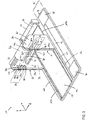
- FIG 1 a training device 10 for therapeutic or athletic training, in particular frontal, dorsal and lateral muscle chains of the upper body, according to an embodiment of the invention is shown.
- the base of the training device 10 is formed by a base plate 12 with a training surface 14.
- the base plate 12 is delimited in the longitudinal direction by a front side 16 and a rear side 18, both of which run perpendicular to the longitudinal direction.
- the base plate 12 is delimited by transverse sides 20 and 22, which are arranged perpendicular to the front side 16 and the rear side 18.
- a main side support 24 is arranged on the right transverse side 20 and a main side support 26 on the left transverse side 22 on the base plate 12.
- a coordinate system is shown in which the arrow in the x direction points forward in a longitudinal direction, the arrow in the y direction in a transverse direction to the right and the arrow in the z direction in a vertical direction upwards.
- the main side supports are firmly connected to the base plate by means of a plurality of screw connections extending from the underside of the base plate.
- a connecting strip 28 is arranged between the main side supports 24 and 26 and is preferably screwed and / or pinned to the main side supports.
- Each of the main side stands 24 and 26 has five upper holding recesses 34, 36 starting from its inside 30, 32, which are each part of an upper receiving means 38, 40 of the respective main side stand 24, 26.
- the recess bases of the corresponding, ie mirror-inverted with respect to an imaginary center plane between the two main side posts 24 and 26, holding recesses 34 and 36 (e.g. 34.1 and 36.1) each define a holding position 42. Since the holding positions are arranged in a mirror-inverted manner, these are also represented by the in Fig. 1 represented transverse axes.
- a trunk and buttocks support 44 is arranged by means of its holding projections 46 and 48 at the third, middle upper holding position 42.3 in the corresponding upper holding recesses 34.3 and 36.3.
- the training device has a leg support 50 which is rotatably mounted with its retaining projections 52 and 54 on bottom side stands 56 and 58, the bottom side stands being firmly connected to the base plate by means of screw connections analogous to the side stands.
- the training device has a footrest 60 which is inclined between the base plate 12 and the leg support 50 towards the base plate.
- the footrest 60 is each integral or flush with the training surface 14 of the base plate 12 educated.
- the bottom plate 12 is in the embodiment of Fig. 1 formed with a wooden panel or a wood composite panel with a wall thickness of several centimeters (in the exemplary embodiment approx. 2-3 cm). This enables, for example, a problem-free attachment of the main side stands 24 and 26 and the floor side stands 56 and 58 to the floor plate 12 by means of screw or pin connections.
- the main side stands 24 and 26 are also formed with a wooden panel or wood composite panel with a wall thickness of several centimeters (in the exemplary embodiment approx. 4 cm), as is the connecting strip 28, which, however, can have a smaller wall thickness.
- the connecting strip 28 is arranged between the main side stands 24 and 26 in order to ensure their vertical position on the floor plate and the parallel arrangement to one another.
- the training surface 14 is formed with a plastic mat, which is inserted flush into the surface of the base plate 12 milled out at this point.
- the training surface 14 is limited to the front part of the training device, in particular because the connecting strip 28 is arranged without upright and relatively deep, so that mainly an exercise execution in the longitudinal direction is provided in front of it.
- the retaining recesses 34 and 36 are milled into the wall thickness or transverse extent of the main side stands 24 and 26 in such a way that they extend from an upper boundary edge 62, 64 inclined towards the leg support 50 and from the inner side surfaces 30 and 32 of the main side stands 24, 26 extend into the material thereof.
- the outer side walls 65 and 67 of the main side stands 24 and 26 are not excluded for the transverse guidance of the trunk and buttocks support 44.
- the trainee can place the trunk and buttocks support in one of the holding positions 42.1 to 42.5 in accordance with the specifications of an exercise or in accordance with his body proportions, where these holding recesses 34 are inclined downwards towards the base of the recess and 36 is securely and rotatably supported by its weight.
- a standing exercise can be performed in which the trainee stands on the training surface 14 and supports himself with his buttocks on the trunk and buttocks support 44 in order to be able to use a Stretching the spine and stretching the upper body to achieve a stretch backwards, including the abdominal muscles.
- the trainee can also perform an exercise in which the feet are placed one behind the other along the face 16 of the base plate 12 on the surface 14 of the footrest 60, with the legs in the ankles being supported on the side of the leg support 50 and the buttocks or hips are supported on the buttocks support 44 to stretch or train the lateral trunk muscle groups.
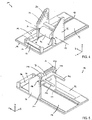
- a training device 10 is shown according to a further exemplary embodiment of the invention, with the addition to the Fig. 1
- a number of other exercises can also be performed with which other muscle groups, in particular of the lower body and / or the extremities, can also be strengthened and / or lengthened.
- the training device 10 provides evidence Fig. 2 the components of a training device Fig. 1 (which are also provided with the same reference numerals, but can be designed differently in individual cases), but also additional components. The following are in particular the differences from a training device Fig. 1 described.
- the base plate 12 is extended to the rear in the longitudinal direction x so that it extends further on the rear side of the main side uprights 24 and 26 than on the front side.
- the base plate 12 is also widened to the right in the transverse direction y, so that it has a side part 66 on the right, beyond the main side stand 24.
- the side part 66 has a front grip surface 68 on the end face 16 of the base plate 12, a rear grip surface 70 in the region of the rear side 18 of the base plate 12 and a grip surface 72 in the longitudinal region in between.
- the grip surfaces 68 and 70 extend essentially along the entire transverse extent of the side part 66 of the base plate 12.
- the grip surface 72 arranged in between extends only in a partial area of this transverse extent which is arranged towards the right main side stand 24.
- a length scale is arranged (not shown).
- the training surface 14 of the base plate 12 extends, unlike in the training device Fig. 1 , from the end face 16 (or the footrest 60) between the main side stands 24 and 26 essentially to the rear side 18 of the base plate 12.
- the main side stands 24 and 26 each have a receiving means 38, 40 with seven holding recesses 34, 36, so that the torso and buttocks support 44 can also be inserted at two further upper holding positions 42.6 and 42.7.
- the main side stands 24 and 26 each have a lower receiving means 74, 76 each with a lower holding recess 78, 80 which define a lower holding position 82 for the torso and buttocks support 44.
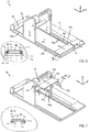
- FIG. Fig. 3 shows the same training device 10 in a laterally rear perspective view.
- the connecting bar 28 is different from the training device according to Fig. 1 , arranged essentially horizontally and in the vertical direction z at a higher position.
- the main side stands 24 and 26 also each have a rear receiving means 84, 86. On each of the rear receiving means 84, 86 there are four rear holding recesses 88, 90 for receiving the in Fig. 5
- the support frame 92 shown is arranged at rear holding positions 94 which are spaced apart differently from the base plate 12 in the vertical direction.
- through-bores 96 and 98 are arranged at the rear holding positions 94 which extend from the outer side walls 65 and 67 to the rear holding recesses 88 and 90, respectively (see FIG Fig. 2 ).
- Another fixing pin bore 100, 102 which is not designed as a through bore, is arranged at a higher position on each outer side wall 65, 67 of the main side stands 24, 26. In each case a fixing pin 104, 106 is inserted into the through hole 96.3, 98.3.
- a side guide 108, 110 is arranged in each case in their respective main plane of extent.
- the main extension plane of each main side stand 24, 26 is arranged essentially parallel to and between its respective inner side surface 30, 32 and outer side surface 65, 67.
- the side guides 108, 110 are used in connection with the Fig. 6 and 8th described in more detail.
- a longitudinal guide 112 or 114 is arranged, which extends essentially from the rear side 18 of the base plate 12 to the footrest 60 on the base plate 12.
- the base plate 12 of the training device 10 according to FIG Fig. 2 is preferably between 2 and 2.5 meters long and between 1 and 1.5 meters wide.
- the main side stands 24, 26 are preferably each between 80 and 120 cm high.
- the side part 66 of the base plate 12 is preferably between 25 and 50 cm wide.
- the training surface 14 of the base plate 12 is preferably between 40 and 65 cm wide.
- the training device 10 according to Fig. 2 is suitable by the opposite Fig. 1 differently designed or additionally introduced features for carrying out further biokinematic exercises and thus for a large number of exercises, the space requirement of the base plate 12 being only insignificantly greater than that of many individual devices for carrying out individual biokinematic exercises.
- a training device 10 can besides the too Fig. 1 Exercises described are performed, among other things, in which the trainee stands, kneels or sits on the training surface 14 behind the main side supports 24 and 26 and holds on to the main side stands with his arms. Furthermore, exercises can be carried out in which elastic gymnastic straps are fixed with the fixing pins 104 and 106, which the trainee can stretch while standing, kneeling or sitting on the training surface 14 behind the main side stands 24, 26.
- the trainee can also perform a leg spreading exercise to stretch the adductors, in which he can hold on to the main side support 24 while he continues to increase the leg spread on the side part 66.
- the trainee stands on the grip surface 68.
- the trainee With increasing leg spread by moving the left leg towards the rear 18 of the base plate 12, the trainee can use the relatively slippery surface beyond the middle grip surface 72 to spread the legs according to his wishes increase.
- the trainee can place his left forefoot on the grip surface 72 so that both legs have a secure stance again.
- an exercise can be carried out starting from the rear grip surface 70 and / or with a side part arranged on the left.
- Fig. 4 the training device 10 is off Fig. 3 shown, the torso and buttocks support 44 being inserted with its holding projections 46 and 48 into the lower holding recesses 78 and 80 of the lower receiving means 74 and 76 of the main side stands 24 and 26.
- the torso and buttocks support 44 is rotatably but firmly and securely mounted at the lower holding position 82, in particular due to its weight in connection with the design of the holding recesses 78 and 80 inclined at an angle to the base plate.
- the arrangement of the trunk and buttocks support 44 at this lower holding position 82 enables, for example, an exercise to stretch the thoracic muscles to be carried out, in which the trainee kneels on the training surface 14 in the longitudinal direction in front of the main side stands and supports his back on the trunk and buttocks support in order to then extend the spine forwards and thus stretch the chest forwards, thereby stretching the muscles.
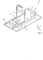
- FIG. 5 shows a training device 10 according to a further exemplary embodiment of the invention. From the training device to Fig. 4 This training device 10 differs in particular in the arrangement of a support frame 92 in the rear holding recesses 88.4 and 90.4, so that the support frame 92 is pushed into the rear holding position 94.4. At this holding position 94.4, the support frame 92 is securely fixed by means of the fixing pins 104 and 106, which extend through the through bores 96.4 and 98.4 into corresponding blind bores (not shown) on a respective transverse outer side of holding projections 116 and 118 of the support frame 92.
- the holding projections 116 and 118 are designed so that they end flush with a rear delimiting edge 120, 122 of the main side stands 24 and 26.
- the support frame 92 has support projections 124 and 126 which are spaced apart from one another in the transverse direction and which in this exemplary embodiment extend parallel to the base plate 12 from the main side supports 24 and 26 in the longitudinal direction to the rear.
- the transverse distance is dimensioned such that at least part of an upper body of the person exercising can be held between the support projections during exercise.
- the trainee can support himself thereon, in particular on the support projections 124 and / or 126, when he is standing, kneeling or sitting on the training surface 14.
- This enables the hands, forearms and / or arms to be comfortably supported (also individually), for example when performing splits exercises, glutaeus exercises, ischio exercises or other exercises.
- Fig. 6 shows a training device 10 according to a further exemplary embodiment of the invention.
- the trunk and buttocks support 44 is not arranged at any of the holding positions, but is removed from the training device.
- a trolley 127 is arranged above the training surface 14, each side having a trolley support 128, 130 each with at least one, in particular two, rollers 132, 134, which are guided in a longitudinal guide groove 136, 138 of the longitudinal guide 112, 114.
- the trolley 127 can be moved along the longitudinal guide 112, 114 in the longitudinal direction x over the training surface 14 between the rear side 18 of the base plate 12 and the footrest 60.
- the trolley 127 is set up approximately in the area of the main side supports 24, 26 on the guide grooves 136 and 138 with its rollers 132 and 134 and (as not shown here) the support frame is preferably also inserted into a low rear receiving recess 94.
- the trainee then supports himself with one knee in the area of the rear side 18 of the base plate 12, supports his arms on the support frame (or, as an experienced trainee, not, as shown here) and places the other foot on the trolley 127. Because the roller carriage 127 is easy to move because of the roller-groove guide, a balancing act can be forced on and on in a controlled manner until a pain point is reached or, if desired, exceeded.
- the trolley 127 is laterally guided with the outer side surfaces of the carriage supports 128 and 130 on the inner side surfaces of the side guides 108 and 110 of the base plate 12.
- Fig. 7 shows a training device 10 according to a further exemplary embodiment of the invention, which differs from the training device of Fig. 6 differs in particular in that the support frame 92 is arranged at the rear holding position 94.4 and is fixed with the fixing pins 104 and 106, the trolley 127, which is shown in FIG Fig. 6 on the longitudinal guide 112, 114 of the base plate 12 was arranged in Fig. 7 rests on a support frame longitudinal guide 140, 142, which is designed analogously to the longitudinal guide 112, 114.
- the trolley 127 has at least one, in particular two, in each of the transverse positions of the longitudinal guide 140, 142 Rollers 144, 146, which can be unrolled on the support carriage longitudinal guide 140, 142.
- the trolley 127 is guided laterally by means of the trolley supports 128, 130 on the laterally outer boundary surfaces of the support projections 124 and 126.
- the rollers 144 and 146 are rotatably mounted in the cross member 148 of the trolley 127.
- the trolley 127 can therefore be moved forwards and backwards in the longitudinal direction on the support frame 92, as indicated by the arrows in FIG Fig. 7 is indicated.
- This can in particular enable a Glutaeus exercise to be carried out in which one knee is bent to the side and the associated lower leg is placed on a training surface 150 of the trolley 127.
- the other leg is placed backwards at an angle on the training surface 14 of the base plate in the area of the rear side 18.
- the inclination of the parked leg is reinforced, whereby the trolley 127 moves on the support projections 124, 126 of the support frame 92 in the longitudinal direction, whereby the Glutäus -Musculature can be stretched.
- FIG. 8 shows a training device 10 according to a further exemplary embodiment of the invention, in which, unlike in FIG Fig. 7 , the support frame 92 and the trolley 127 are not arranged on the training device 10, but a forefoot stand 152 is.
- the forefoot stand 152 has a stand 153 for fixing a stone element 154 attached to it with a transverse edge 156 for erecting the forefoot.
- the stand frame also has a guide surface 158, 160 on each transverse side, each of which is designed such that it interacts with the side guide 108, 110 of the base plate 12 for transverse guidance and for establishing a rotational alignment of the forefoot stand 152.
- a training device 10 with such a forefoot stand 152 the trainee can train or lengthen the same by placing his forefeet or a forefoot on the transverse edge 156 of the stone element 154 and then stretching and contracting the ischio muscles.
- the forefoot stand 152 By fitting the forefoot stand 152 on its guide surfaces 158 and 160 into the side guides 108 and 110 of the training device 10, a secure, firm stand on the forefoot stand 152 is ensured.
- Experienced exercisers perform this exercise without supporting their hands or arms; Less experienced exercisers can use the exercise device 10 to support their arms or hands in addition, arrange the support frame 92 at one of the rear holding positions 94, which enables a more stable execution of the exercise.
- the training devices 10 shown differ only in the arrangement (yes / no / at a certain holding position) of the removable components, such as the trunk and buttocks support 44, the support frame 92, the trolley 127 and the forefoot stand 152. That these components individually and / or can be arranged in any combination at any, meaningful positions on the training device 10, even if only individual combinations in the Figures 2-8 are shown, of course, insofar as this is useful for performing biokinematic exercises and / or for adapting the training device 10 to the body proportions of a person exercising.
Landscapes
- Health & Medical Sciences (AREA)
- Orthopedic Medicine & Surgery (AREA)
- General Health & Medical Sciences (AREA)
- Physical Education & Sports Medicine (AREA)
- Engineering & Computer Science (AREA)
- Biomedical Technology (AREA)
- Neurology (AREA)
- Pulmonology (AREA)
- Life Sciences & Earth Sciences (AREA)
- Biophysics (AREA)
- Rehabilitation Tools (AREA)
Claims (16)
- Appareil d'entraînement (10) pour des exercices de mouvement thérapeutiques et sportifs, comprenant :- une plaque de base (12) ayant une surface d'entraînement (14),- un support de jambes (50) s'étendant au-dessus de la plaque de base (12) sur un côté frontal (16) et le long d'une direction transversale (y) de la plaque de base (12),- deux montants latéraux principaux (24, 26) s'étendant vers le haut à partir de la plaque de base (12) et fixés à celle-ci, qui sont espacés l'un de l'autre dans la direction transversale (y) de la plaque de base (12) et qui sont espacés de manière sensiblement équidistante du support de jambes (50) dans une direction longitudinale (x) perpendiculaire à la direction transversale (y) de la plaque de base (12), une zone d'espacement ainsi formée sur la plaque de base (12) étant réalisée comme au moins une partie de la surface d'entraînement (14), et- un support de torse-fesses (44) disposé sur les montants latéraux principaux (24, 26) au-dessus de la plaque de base (12) et s'étendant entre les montants latéraux principaux (24, 26),dans lequel
un moyen de réception supérieur (38, 40) pour le support de torse-fesses (44) est disposé sur chacun des deux montants latéraux principaux (24, 26) et comprend deux ou plusieurs évidements de retenue supérieurs (34, 36) dans des positions de retenue supérieures différentes (42), les évidements de retenue (34, 36) des deux montants latéraux principaux (24, 26) étant réalisés symétriques, en particulier étant disposés dans des positions symétriques, par rapport à un plan médian imaginaire entre les montants latéraux principaux (24, 26),
caractérisé en ce que
les deux montants latéraux principaux (24, 26) présentent chacun un moyen de réception arrière (84, 86) pour recevoir un cadre de support (92). - Appareil d'entraînement (10) selon la revendication 1, dans lequel chacun des montants latéraux principaux (24, 26) est formé d'une plaque et/ou d'un bâti et présente un plan d'extension principal, les plans d'extension principaux des deux montants latéraux principaux (24, 26) étant disposés au moins sensiblement perpendiculairement à la plaque de base (12), parallèlement entre eux et/ou dans la direction longitudinale (x) de la plaque de base (12).
- Appareil d'entraînement (10) selon l'une des revendications précédentes, dans lequel des moyens de réception inférieurs (74, 76) pour le support de torse/fesses (44) sont disposés à symétrie respectivement sur les deux montants latéraux principaux (24, 26), les moyens de réception inférieurs (74, 76) présentant au moins un évidement de retenue inférieur (78, 80) disposé à une position de retenue inférieure (82) et espacé vers le bas des positions de retenue supérieures (42), de préférence de leur trajectoire (39, 41).
- Appareil d'entraînement (10) selon l'une des revendications précédentes, comprenant en outre un cadre de support (92) disposé entre les montants latéraux principaux (24, 26), pour la réception duquel des moyens de réception arrière (84, 86) sont disposés à symétrie respectivement sur les deux montants latéraux principaux (24, 26), chacun desdits moyens de réception arrière (84, 86) comprenant deux ou plusieurs évidements de retenue arrière (88, 90) dans différentes positions de retenue arrière (94), qui sont espacés du support de jambes (50) en direction longitudinale (x) plus loin que le moyen de réception supérieur (38, 40).
- Appareil d'entraînement (10) selon l'une des revendications précédentes, dans lequel les moyens de réception supérieur, inférieur et/ou arrière (38, 40 ; 74, 76 ; 84, 86) et/ou au moins un évidement de retenue supérieur, inférieur et/ou arrière (34, 36 ; 78, 80 ; 88, 90) de chaque montant latéral principal (24, 26) s'étendent individuellement ou au moins partiellement conjointement à partir d'un contour extérieur (61, 63), en particulier à partir d'un bord de délimitation extérieur (62, 64), du montant latéral principal (24, 26) jusque dans l'extension transversale, en particulier dans le matériau et/ou dans l'épaisseur de paroi de celui-ci.
- Appareil d'entraînement (10) selon l'une des revendications précédentes, dans lequel- le moyen de réception supérieur (38, 40) s'étend à partir d'un bord de délimitation supérieur (62a, 64a) incliné vers le support de jambes (50),- le moyen de réception inférieur (74, 76) s'étend à partir d'un bord de délimitation avant (62b, 64b) s'étendant de préférence sensiblement dans la direction verticale (z) de la plaque de base (12),
et/ou- le moyen de réception arrière (84, 86) s'étend à partir d'un bord de délimitation arrière (62c, 64c) s'étendant de préférence sensiblement dans la direction verticale (z) de la plaque de base (12)du montant latéral principal (24, 26) jusque dans l'extension transversale, en particulier dans le matériau et/ou dans l'épaisseur de paroi de celui-ci. - Appareil d'entraînement (10) selon l'une des revendications précédentes 4 à 6, comprenant un cadre de support (92) qui présente au moins une, en particulier deux saillies d'appui (124, 126) qui sont disposées à symétrie par rapport au plan médian imaginaire et qui s'étendent sensiblement dans la direction longitudinale (x) de la plaque de base (12).
- Appareil d'entraînement (10) selon l'une des revendications précédentes, dans lequel la plaque de base (12) s'étend dans la direction longitudinale (x) également sur un côté des montants latéraux principaux (24, 26) détourné du support de jambes (50), en particulier au moins aussi loin que sur le côté des montants latéraux principaux (24, 26) tourné vers le support de jambes (50).
- Appareil d'entraînement (10) selon la revendication précédente,
dans lequel la surface d'entraînement (14) s'étend à travers les montants latéraux principaux (24, 26) dans la direction longitudinale (x) sensiblement entre le côté frontal (16) et un côté arrière (18) de la plaque de base (12). - Appareil d'entraînement (10) selon l'une des revendications précédentes, comprenant en outre un chariot roulant (127) qui est disposé au-dessus de la surface d'entraînement (14) et qui peut être déplacé en va-et-vient le long d'une partie au moins de l'extension entre le côté frontal (16) et le côté arrière (18) de la plaque de base (12), en particulier en passant à travers les montants latéraux principaux (24, 26), par dessus la surface d'entraînement (14), au moyen de roulettes (132, 134) disposées sur le chariot roulant (127), dans lequel
au moins un guidage longitudinal (112, 114) est disposé sur la plaque de base (12), guidage sur lequel les roulettes (132, 134) peuvent rouler. - Appareil d'entraînement (10) selon la revendication 10,
dans lequel- le chariot roulant (127) comprend un élément porteur transversal (128) qui est réalisé de telle sorte que le chariot roulant (127) peut être posé sur les saillies d'appui (124, 126) du cadre de support (92), et de préférence au moins une roulette (144, 146) est montée de manière rotative dans l'élément porteur transversal (128) dans deux positions définies par l'espacement transversal des saillies d'appui (124, 126), et- chacun des supports de chariot (128, 130) du chariot roulant (127) présente une surface latérale intérieure qui est réalisée de manière à coopérer avec une surface de guidage du cadre de support (92) disposée intérieurement le long de chaque saillie d'appui (124, 126), lorsque le chariot roulant (127) est posé sur les saillies d'appui (124, 126). - Appareil d'entraînement (10) selon l'une des revendications précédentes 4 à 11,
dans lequel les évidements de retenue supérieurs, inférieurs et/ou arrière (34, 36 ; 78, 80 ; 88, 90) des montants latéraux principaux (24, 26) s'étendent chacun à partir du côté intérieur uniquement dans une partie de l'extension transversale du montant latéral principal (24, 26),
et un évidement traversant, en particulier un alésage traversant (96, 98), est disposé sur au moins un évidement de retenue supérieur, inférieur et/ou arrière (34, 36 ; 78, 80 ; 88, 90) de chaque montant latéral principal (24, 26), dans lequel peut être inséré respectivement un plot de fixation (104, 106) qui est réalisé pour- fixer le cadre de support (92), en particulier à une saillie de retenue (116, 118), dans un évidement de retenue arrière (88, 90), et/ou- fixer une bande de gymnastique au montant latéral principal (24, 26). - Appareil d'entraînement (10) selon l'une des revendications précédentes, dans lequel, sur au moins l'un des montants latéraux principaux (24, 26), sur son côté détourné du support de torse-fesses (44), la plaque de base (12) présente, le long d'au moins une partie de l'extension longitudinale de la plaque de base (12), une portion latérale (66) avec une extension transversale supplémentaire, en particulier d'au moins 25 cm en dehors de l'espacement transversal des deux montants latéraux principaux (24, 26).
- Appareil d'entraînement (10) selon l'une des revendications précédentes, comprenant en outre un repose-avant-pied (152), le repose-avant-pied (152) comprenant de chaque côté une surface de guidage (158, 160) réalisée de manière à coopérer avec un guidage latéral (108, 110) de la plaque de base (12).
- Appareil d'entraînement (10) selon l'une des revendications précédentes, comprenant en outre un repose-pied (60) incliné par rapport à la plaque de base (12) et disposé de préférence entre le support de jambes (50) et la plaque de base (12).
- Appareil d'entraînement (10) selon l'une des revendications précédentes, dont la plaque de base (12) comprend au moins deux plaques partielles de base pouvant être reliées solidairement de manière répétée et temporaire et pouvant être séparées de manière non destructive, en particulier une plaque partielle de montant latéral principal, une plaque partielle de support de jambes, une plaque partielle arrière et/ou au moins une plaque partielle latérale.
Applications Claiming Priority (4)
| Application Number | Priority Date | Filing Date | Title |
|---|---|---|---|
| DE102014014616 | 2014-10-02 | ||
| DE102014015229.4A DE102014015229B4 (de) | 2014-10-02 | 2014-10-15 | Träningsgerät mit einer Bodenplatte und zwei Hauptseitenständern |
| DE202014008246.4U DE202014008246U1 (de) | 2014-10-02 | 2014-10-15 | Trainingsgerät mit einer Bodenplatte und zwei Hauptseitenständern |
| PCT/EP2015/001924 WO2016050352A1 (fr) | 2014-10-02 | 2015-09-29 | Appareil d'entraînement pourvu d'une plaque de base et de deux montants latéraux principaux |
Publications (2)
| Publication Number | Publication Date |
|---|---|
| EP3200883A1 EP3200883A1 (fr) | 2017-08-09 |
| EP3200883B1 true EP3200883B1 (fr) | 2021-05-26 |
Family
ID=55235233
Family Applications (1)
| Application Number | Title | Priority Date | Filing Date |
|---|---|---|---|
| EP15784276.6A Active EP3200883B1 (fr) | 2014-10-02 | 2015-09-29 | Appareil d'entraînement pourvu d'une plaque de base et de deux montants latéraux principaux |
Country Status (4)
| Country | Link |
|---|---|
| EP (1) | EP3200883B1 (fr) |
| AT (1) | AT15484U3 (fr) |
| DE (2) | DE202014008246U1 (fr) |
| WO (1) | WO2016050352A1 (fr) |
Families Citing this family (1)
| Publication number | Priority date | Publication date | Assignee | Title |
|---|---|---|---|---|
| DE102020206270B3 (de) * | 2020-05-19 | 2021-05-06 | Schreinerei Einsiedler - Planung Entwicklung und Realisierung | Gymnastikvorrichtung |
Citations (1)
| Publication number | Priority date | Publication date | Assignee | Title |
|---|---|---|---|---|
| DE202014003356U1 (de) * | 2014-04-19 | 2014-09-23 | Michael Helbing | Hüftmobilisationsgerät zu Mobilisation und Kräftigung der hüftumgebenden Muskulatur |
Family Cites Families (7)
| Publication number | Priority date | Publication date | Assignee | Title |
|---|---|---|---|---|
| US5405306A (en) * | 1994-02-25 | 1995-04-11 | Goldsmith; Daniel S. | Stretching apparatus |
| US6669611B2 (en) * | 2000-02-11 | 2003-12-30 | Jean-Guy Raymond | Abdominal exerciser device |
| DE202010010745U1 (de) | 2010-07-28 | 2011-01-13 | Rückgrat Freiburg-Stühlinger GmbH Sport- und Gesundheitscenter | Heil- und sportgymnastisches Gerät, vorwiegend für den Rückenbereich |
| DE202010011891U1 (de) * | 2010-08-27 | 2010-12-30 | Rückrat Freiburg Stühlinger GmbH | Heil- und sportgymnastisches Gerät, vorwiegend für den Nacken, der alltäglichen Grundspannung widersprechende und somit entlastende Dehnübungen ermöglicht |
| US8801579B2 (en) * | 2011-08-02 | 2014-08-12 | Dynamic Sports Products, LLC | Muscle stretching and massaging apparatus |
| US9114272B2 (en) * | 2012-03-12 | 2015-08-25 | Donkey Sit Fitness, Llc | Portable adjustable multi-purpose exercise device |
| US20140228189A1 (en) * | 2013-02-14 | 2014-08-14 | Pierre Fortin | Exercise device |
-
2014
- 2014-10-15 DE DE202014008246.4U patent/DE202014008246U1/de not_active Expired - Lifetime
- 2014-10-15 DE DE102014015229.4A patent/DE102014015229B4/de not_active Expired - Fee Related
-
2015
- 2015-09-29 WO PCT/EP2015/001924 patent/WO2016050352A1/fr not_active Ceased
- 2015-09-29 AT ATGM322/2016U patent/AT15484U3/de not_active IP Right Cessation
- 2015-09-29 EP EP15784276.6A patent/EP3200883B1/fr active Active
Patent Citations (1)
| Publication number | Priority date | Publication date | Assignee | Title |
|---|---|---|---|---|
| DE202014003356U1 (de) * | 2014-04-19 | 2014-09-23 | Michael Helbing | Hüftmobilisationsgerät zu Mobilisation und Kräftigung der hüftumgebenden Muskulatur |
Also Published As
| Publication number | Publication date |
|---|---|
| EP3200883A1 (fr) | 2017-08-09 |
| WO2016050352A1 (fr) | 2016-04-07 |
| DE102014015229B4 (de) | 2018-09-13 |
| AT15484U3 (de) | 2018-03-15 |
| AT15484U2 (de) | 2017-10-15 |
| DE202014008246U1 (de) | 2016-01-11 |
| DE102014015229A1 (de) | 2016-04-07 |
Similar Documents
| Publication | Publication Date | Title |
|---|---|---|
| EP3551300B1 (fr) | Appareil d'entraînement pour effectuer des exercices d'équilibre, de méditation et/ou de yoga | |
| DE102015113113B4 (de) | Therapie-Trainings-Gerät | |
| EP2962738B1 (fr) | Appareil de sport pouvant rouler | |
| DE3436120C1 (de) | Trainingsgeraet zum Trainieren der Oberschenkel- und Wadenmuskeln | |
| DE69803814T2 (de) | Vorrichtung zum Muskeltraining | |
| DE9318163U1 (de) | Mehrzweck-Trainingsgerät | |
| DE69523473T2 (de) | Gymnastikgerät | |
| DE102014015229B4 (de) | Träningsgerät mit einer Bodenplatte und zwei Hauptseitenständern | |
| DE3425200A1 (de) | Trainings-, sport-, fitness- bzw. spielgeraet | |
| EP1955735B1 (fr) | Trampoline | |
| EP1952847A1 (fr) | Appareil d'entraînement destiné à l'entretien de la musculature diagonale de mouvement, en particulier pour la technique de ski intérieur | |
| DE102004027524B4 (de) | Multifunktionales Trainingsgerät zur Stärkung der Bein- und Rückenmuskulatur | |
| WO2004110566A1 (fr) | Appareil de sport destine a la course stationnaire en position assise | |
| DE4231446C2 (de) | Sprossenreck für Mobilisationstraining und Krankengymnastik | |
| DE202007009543U1 (de) | Sport- und Fitnessgerät | |
| DE102019118632B3 (de) | Trainingsgerät | |
| DE60222398T2 (de) | Vorrichtung zum Muskeltraining einer Person | |
| DE602004007396T2 (de) | Multifunktionelles Trainingsgerät mit schaukelndem Fuss und mehreren Griffen | |
| DE102016104576A1 (de) | Trainingsgerät zur Übung der Gesäßmuskulatur | |
| DE102021126561A1 (de) | Therapiegerät | |
| EP2588206A1 (fr) | Dispositif permettant la coordination des mouvements | |
| DE3301738A1 (de) | Rueckenschwimmtrainer | |
| DE29622192U1 (de) | Kombiniertes Gymnastikgerät für Erwachsene | |
| DE20214534U1 (de) | Trainingsgerät zum Training der Arm-, Bauch- und Rückenmuskulatur von Personen | |
| DE202010011891U1 (de) | Heil- und sportgymnastisches Gerät, vorwiegend für den Nacken, der alltäglichen Grundspannung widersprechende und somit entlastende Dehnübungen ermöglicht |
Legal Events
| Date | Code | Title | Description |
|---|---|---|---|
| STAA | Information on the status of an ep patent application or granted ep patent |
Free format text: STATUS: THE INTERNATIONAL PUBLICATION HAS BEEN MADE |
|
| PUAI | Public reference made under article 153(3) epc to a published international application that has entered the european phase |
Free format text: ORIGINAL CODE: 0009012 |
|
| STAA | Information on the status of an ep patent application or granted ep patent |
Free format text: STATUS: REQUEST FOR EXAMINATION WAS MADE |
|
| 17P | Request for examination filed |
Effective date: 20170425 |
|
| AK | Designated contracting states |
Kind code of ref document: A1 Designated state(s): AL AT BE BG CH CY CZ DE DK EE ES FI FR GB GR HR HU IE IS IT LI LT LU LV MC MK MT NL NO PL PT RO RS SE SI SK SM TR |
|
| AX | Request for extension of the european patent |
Extension state: BA ME |
|
| DAV | Request for validation of the european patent (deleted) | ||
| DAX | Request for extension of the european patent (deleted) | ||
| STAA | Information on the status of an ep patent application or granted ep patent |
Free format text: STATUS: EXAMINATION IS IN PROGRESS |
|
| 17Q | First examination report despatched |
Effective date: 20191010 |
|
| GRAP | Despatch of communication of intention to grant a patent |
Free format text: ORIGINAL CODE: EPIDOSNIGR1 |
|
| STAA | Information on the status of an ep patent application or granted ep patent |
Free format text: STATUS: GRANT OF PATENT IS INTENDED |
|
| INTG | Intention to grant announced |
Effective date: 20201214 |
|
| GRAS | Grant fee paid |
Free format text: ORIGINAL CODE: EPIDOSNIGR3 |
|
| GRAA | (expected) grant |
Free format text: ORIGINAL CODE: 0009210 |
|
| STAA | Information on the status of an ep patent application or granted ep patent |
Free format text: STATUS: THE PATENT HAS BEEN GRANTED |
|
| AK | Designated contracting states |
Kind code of ref document: B1 Designated state(s): AL AT BE BG CH CY CZ DE DK EE ES FI FR GB GR HR HU IE IS IT LI LT LU LV MC MK MT NL NO PL PT RO RS SE SI SK SM TR |
|
| REG | Reference to a national code |
Ref country code: GB Ref legal event code: FG4D Free format text: NOT ENGLISH |
|
| REG | Reference to a national code |
Ref country code: CH Ref legal event code: EP |
|
| REG | Reference to a national code |
Ref country code: DE Ref legal event code: R096 Ref document number: 502015014754 Country of ref document: DE |
|
| REG | Reference to a national code |
Ref country code: AT Ref legal event code: REF Ref document number: 1395622 Country of ref document: AT Kind code of ref document: T Effective date: 20210615 |
|
| REG | Reference to a national code |
Ref country code: IE Ref legal event code: FG4D Free format text: LANGUAGE OF EP DOCUMENT: GERMAN |
|
| REG | Reference to a national code |
Ref country code: LT Ref legal event code: MG9D |
|
| PG25 | Lapsed in a contracting state [announced via postgrant information from national office to epo] |
Ref country code: LT Free format text: LAPSE BECAUSE OF FAILURE TO SUBMIT A TRANSLATION OF THE DESCRIPTION OR TO PAY THE FEE WITHIN THE PRESCRIBED TIME-LIMIT Effective date: 20210526 Ref country code: FI Free format text: LAPSE BECAUSE OF FAILURE TO SUBMIT A TRANSLATION OF THE DESCRIPTION OR TO PAY THE FEE WITHIN THE PRESCRIBED TIME-LIMIT Effective date: 20210526 Ref country code: BG Free format text: LAPSE BECAUSE OF FAILURE TO SUBMIT A TRANSLATION OF THE DESCRIPTION OR TO PAY THE FEE WITHIN THE PRESCRIBED TIME-LIMIT Effective date: 20210826 Ref country code: HR Free format text: LAPSE BECAUSE OF FAILURE TO SUBMIT A TRANSLATION OF THE DESCRIPTION OR TO PAY THE FEE WITHIN THE PRESCRIBED TIME-LIMIT Effective date: 20210526 |
|
| PGFP | Annual fee paid to national office [announced via postgrant information from national office to epo] |
Ref country code: MC Payment date: 20210920 Year of fee payment: 7 Ref country code: LU Payment date: 20210921 Year of fee payment: 7 |
|
| REG | Reference to a national code |
Ref country code: NL Ref legal event code: MP Effective date: 20210526 |
|
| PG25 | Lapsed in a contracting state [announced via postgrant information from national office to epo] |
Ref country code: IS Free format text: LAPSE BECAUSE OF FAILURE TO SUBMIT A TRANSLATION OF THE DESCRIPTION OR TO PAY THE FEE WITHIN THE PRESCRIBED TIME-LIMIT Effective date: 20210926 Ref country code: LV Free format text: LAPSE BECAUSE OF FAILURE TO SUBMIT A TRANSLATION OF THE DESCRIPTION OR TO PAY THE FEE WITHIN THE PRESCRIBED TIME-LIMIT Effective date: 20210526 Ref country code: GR Free format text: LAPSE BECAUSE OF FAILURE TO SUBMIT A TRANSLATION OF THE DESCRIPTION OR TO PAY THE FEE WITHIN THE PRESCRIBED TIME-LIMIT Effective date: 20210827 Ref country code: PL Free format text: LAPSE BECAUSE OF FAILURE TO SUBMIT A TRANSLATION OF THE DESCRIPTION OR TO PAY THE FEE WITHIN THE PRESCRIBED TIME-LIMIT Effective date: 20210526 Ref country code: NO Free format text: LAPSE BECAUSE OF FAILURE TO SUBMIT A TRANSLATION OF THE DESCRIPTION OR TO PAY THE FEE WITHIN THE PRESCRIBED TIME-LIMIT Effective date: 20210826 Ref country code: PT Free format text: LAPSE BECAUSE OF FAILURE TO SUBMIT A TRANSLATION OF THE DESCRIPTION OR TO PAY THE FEE WITHIN THE PRESCRIBED TIME-LIMIT Effective date: 20210927 Ref country code: RS Free format text: LAPSE BECAUSE OF FAILURE TO SUBMIT A TRANSLATION OF THE DESCRIPTION OR TO PAY THE FEE WITHIN THE PRESCRIBED TIME-LIMIT Effective date: 20210526 Ref country code: SE Free format text: LAPSE BECAUSE OF FAILURE TO SUBMIT A TRANSLATION OF THE DESCRIPTION OR TO PAY THE FEE WITHIN THE PRESCRIBED TIME-LIMIT Effective date: 20210526 |
|
| PG25 | Lapsed in a contracting state [announced via postgrant information from national office to epo] |
Ref country code: NL Free format text: LAPSE BECAUSE OF FAILURE TO SUBMIT A TRANSLATION OF THE DESCRIPTION OR TO PAY THE FEE WITHIN THE PRESCRIBED TIME-LIMIT Effective date: 20210526 |
|
| PG25 | Lapsed in a contracting state [announced via postgrant information from national office to epo] |
Ref country code: CZ Free format text: LAPSE BECAUSE OF FAILURE TO SUBMIT A TRANSLATION OF THE DESCRIPTION OR TO PAY THE FEE WITHIN THE PRESCRIBED TIME-LIMIT Effective date: 20210526 Ref country code: DK Free format text: LAPSE BECAUSE OF FAILURE TO SUBMIT A TRANSLATION OF THE DESCRIPTION OR TO PAY THE FEE WITHIN THE PRESCRIBED TIME-LIMIT Effective date: 20210526 Ref country code: EE Free format text: LAPSE BECAUSE OF FAILURE TO SUBMIT A TRANSLATION OF THE DESCRIPTION OR TO PAY THE FEE WITHIN THE PRESCRIBED TIME-LIMIT Effective date: 20210526 Ref country code: SM Free format text: LAPSE BECAUSE OF FAILURE TO SUBMIT A TRANSLATION OF THE DESCRIPTION OR TO PAY THE FEE WITHIN THE PRESCRIBED TIME-LIMIT Effective date: 20210526 Ref country code: SK Free format text: LAPSE BECAUSE OF FAILURE TO SUBMIT A TRANSLATION OF THE DESCRIPTION OR TO PAY THE FEE WITHIN THE PRESCRIBED TIME-LIMIT Effective date: 20210526 Ref country code: ES Free format text: LAPSE BECAUSE OF FAILURE TO SUBMIT A TRANSLATION OF THE DESCRIPTION OR TO PAY THE FEE WITHIN THE PRESCRIBED TIME-LIMIT Effective date: 20210526 Ref country code: RO Free format text: LAPSE BECAUSE OF FAILURE TO SUBMIT A TRANSLATION OF THE DESCRIPTION OR TO PAY THE FEE WITHIN THE PRESCRIBED TIME-LIMIT Effective date: 20210526 |
|
| REG | Reference to a national code |
Ref country code: DE Ref legal event code: R097 Ref document number: 502015014754 Country of ref document: DE |
|
| PLBE | No opposition filed within time limit |
Free format text: ORIGINAL CODE: 0009261 |
|
| STAA | Information on the status of an ep patent application or granted ep patent |
Free format text: STATUS: NO OPPOSITION FILED WITHIN TIME LIMIT |
|
| 26N | No opposition filed |
Effective date: 20220301 |
|
| REG | Reference to a national code |
Ref country code: BE Ref legal event code: MM Effective date: 20210930 |
|
| PG25 | Lapsed in a contracting state [announced via postgrant information from national office to epo] |
Ref country code: IS Free format text: LAPSE BECAUSE OF FAILURE TO SUBMIT A TRANSLATION OF THE DESCRIPTION OR TO PAY THE FEE WITHIN THE PRESCRIBED TIME-LIMIT Effective date: 20210926 Ref country code: AL Free format text: LAPSE BECAUSE OF FAILURE TO SUBMIT A TRANSLATION OF THE DESCRIPTION OR TO PAY THE FEE WITHIN THE PRESCRIBED TIME-LIMIT Effective date: 20210526 |
|
| PG25 | Lapsed in a contracting state [announced via postgrant information from national office to epo] |
Ref country code: IT Free format text: LAPSE BECAUSE OF FAILURE TO SUBMIT A TRANSLATION OF THE DESCRIPTION OR TO PAY THE FEE WITHIN THE PRESCRIBED TIME-LIMIT Effective date: 20210526 Ref country code: IE Free format text: LAPSE BECAUSE OF NON-PAYMENT OF DUE FEES Effective date: 20210929 Ref country code: BE Free format text: LAPSE BECAUSE OF NON-PAYMENT OF DUE FEES Effective date: 20210930 |
|
| PG25 | Lapsed in a contracting state [announced via postgrant information from national office to epo] |
Ref country code: MC Free format text: LAPSE BECAUSE OF NON-PAYMENT OF DUE FEES Effective date: 20220930 |
|
| PG25 | Lapsed in a contracting state [announced via postgrant information from national office to epo] |
Ref country code: HU Free format text: LAPSE BECAUSE OF FAILURE TO SUBMIT A TRANSLATION OF THE DESCRIPTION OR TO PAY THE FEE WITHIN THE PRESCRIBED TIME-LIMIT; INVALID AB INITIO Effective date: 20150929 |
|
| PG25 | Lapsed in a contracting state [announced via postgrant information from national office to epo] |
Ref country code: LU Free format text: LAPSE BECAUSE OF NON-PAYMENT OF DUE FEES Effective date: 20220929 Ref country code: CY Free format text: LAPSE BECAUSE OF FAILURE TO SUBMIT A TRANSLATION OF THE DESCRIPTION OR TO PAY THE FEE WITHIN THE PRESCRIBED TIME-LIMIT Effective date: 20210526 |
|
| PG25 | Lapsed in a contracting state [announced via postgrant information from national office to epo] |
Ref country code: MK Free format text: LAPSE BECAUSE OF FAILURE TO SUBMIT A TRANSLATION OF THE DESCRIPTION OR TO PAY THE FEE WITHIN THE PRESCRIBED TIME-LIMIT Effective date: 20210526 |
|
| PG25 | Lapsed in a contracting state [announced via postgrant information from national office to epo] |
Ref country code: MT Free format text: LAPSE BECAUSE OF FAILURE TO SUBMIT A TRANSLATION OF THE DESCRIPTION OR TO PAY THE FEE WITHIN THE PRESCRIBED TIME-LIMIT Effective date: 20210526 |
|
| PGFP | Annual fee paid to national office [announced via postgrant information from national office to epo] |
Ref country code: FR Payment date: 20240924 Year of fee payment: 10 |
|
| REG | Reference to a national code |
Ref country code: CH Ref legal event code: U11 Free format text: ST27 STATUS EVENT CODE: U-0-0-U10-U11 (AS PROVIDED BY THE NATIONAL OFFICE) Effective date: 20251001 |
|
| PGFP | Annual fee paid to national office [announced via postgrant information from national office to epo] |
Ref country code: GB Payment date: 20250923 Year of fee payment: 11 |
|
| PGFP | Annual fee paid to national office [announced via postgrant information from national office to epo] |
Ref country code: AT Payment date: 20250918 Year of fee payment: 11 |
|
| PG25 | Lapsed in a contracting state [announced via postgrant information from national office to epo] |
Ref country code: TR Free format text: LAPSE BECAUSE OF FAILURE TO SUBMIT A TRANSLATION OF THE DESCRIPTION OR TO PAY THE FEE WITHIN THE PRESCRIBED TIME-LIMIT Effective date: 20210526 |
|
| REG | Reference to a national code |
Ref country code: DE Ref legal event code: R082 Ref document number: 502015014754 Country of ref document: DE Representative=s name: ALPSPITZ IP ALLGAYER UND PARTNER PATENTANWAELT, DE |
|
| PGFP | Annual fee paid to national office [announced via postgrant information from national office to epo] |
Ref country code: DE Payment date: 20251020 Year of fee payment: 11 |
|
| PGFP | Annual fee paid to national office [announced via postgrant information from national office to epo] |
Ref country code: CH Payment date: 20251001 Year of fee payment: 11 |
|
| PG25 | Lapsed in a contracting state [announced via postgrant information from national office to epo] |
Ref country code: FR Free format text: LAPSE BECAUSE OF NON-PAYMENT OF DUE FEES Effective date: 20250930 |