EP3200964B1 - Buse pour une extrudeuse avec contrôle de flux - Google Patents
Buse pour une extrudeuse avec contrôle de flux Download PDFInfo
- Publication number
- EP3200964B1 EP3200964B1 EP14903319.3A EP14903319A EP3200964B1 EP 3200964 B1 EP3200964 B1 EP 3200964B1 EP 14903319 A EP14903319 A EP 14903319A EP 3200964 B1 EP3200964 B1 EP 3200964B1
- Authority
- EP
- European Patent Office
- Prior art keywords
- nozzle
- along
- flow
- apertures
- channels
- Prior art date
- Legal status (The legal status is an assumption and is not a legal conclusion. Google has not performed a legal analysis and makes no representation as to the accuracy of the status listed.)
- Active
Links
Images



Classifications
-
- B—PERFORMING OPERATIONS; TRANSPORTING
- B29—WORKING OF PLASTICS; WORKING OF SUBSTANCES IN A PLASTIC STATE IN GENERAL
- B29C—SHAPING OR JOINING OF PLASTICS; SHAPING OF MATERIAL IN A PLASTIC STATE, NOT OTHERWISE PROVIDED FOR; AFTER-TREATMENT OF THE SHAPED PRODUCTS, e.g. REPAIRING
- B29C48/00—Extrusion moulding, i.e. expressing the moulding material through a die or nozzle which imparts the desired form; Apparatus therefor
- B29C48/25—Component parts, details or accessories; Auxiliary operations
- B29C48/92—Measuring, controlling or regulating
-
- B—PERFORMING OPERATIONS; TRANSPORTING
- B29—WORKING OF PLASTICS; WORKING OF SUBSTANCES IN A PLASTIC STATE IN GENERAL
- B29C—SHAPING OR JOINING OF PLASTICS; SHAPING OF MATERIAL IN A PLASTIC STATE, NOT OTHERWISE PROVIDED FOR; AFTER-TREATMENT OF THE SHAPED PRODUCTS, e.g. REPAIRING
- B29C48/00—Extrusion moulding, i.e. expressing the moulding material through a die or nozzle which imparts the desired form; Apparatus therefor
- B29C48/03—Extrusion moulding, i.e. expressing the moulding material through a die or nozzle which imparts the desired form; Apparatus therefor characterised by the shape of the extruded material at extrusion
- B29C48/07—Flat, e.g. panels
-
- B—PERFORMING OPERATIONS; TRANSPORTING
- B29—WORKING OF PLASTICS; WORKING OF SUBSTANCES IN A PLASTIC STATE IN GENERAL
- B29C—SHAPING OR JOINING OF PLASTICS; SHAPING OF MATERIAL IN A PLASTIC STATE, NOT OTHERWISE PROVIDED FOR; AFTER-TREATMENT OF THE SHAPED PRODUCTS, e.g. REPAIRING
- B29C48/00—Extrusion moulding, i.e. expressing the moulding material through a die or nozzle which imparts the desired form; Apparatus therefor
- B29C48/03—Extrusion moulding, i.e. expressing the moulding material through a die or nozzle which imparts the desired form; Apparatus therefor characterised by the shape of the extruded material at extrusion
- B29C48/12—Articles with an irregular circumference when viewed in cross-section, e.g. window profiles
-
- B—PERFORMING OPERATIONS; TRANSPORTING
- B29—WORKING OF PLASTICS; WORKING OF SUBSTANCES IN A PLASTIC STATE IN GENERAL
- B29C—SHAPING OR JOINING OF PLASTICS; SHAPING OF MATERIAL IN A PLASTIC STATE, NOT OTHERWISE PROVIDED FOR; AFTER-TREATMENT OF THE SHAPED PRODUCTS, e.g. REPAIRING
- B29C48/00—Extrusion moulding, i.e. expressing the moulding material through a die or nozzle which imparts the desired form; Apparatus therefor
- B29C48/25—Component parts, details or accessories; Auxiliary operations
- B29C48/255—Flow control means, e.g. valves
- B29C48/2556—Flow control means, e.g. valves provided in or in the proximity of dies
-
- B—PERFORMING OPERATIONS; TRANSPORTING
- B29—WORKING OF PLASTICS; WORKING OF SUBSTANCES IN A PLASTIC STATE IN GENERAL
- B29C—SHAPING OR JOINING OF PLASTICS; SHAPING OF MATERIAL IN A PLASTIC STATE, NOT OTHERWISE PROVIDED FOR; AFTER-TREATMENT OF THE SHAPED PRODUCTS, e.g. REPAIRING
- B29C48/00—Extrusion moulding, i.e. expressing the moulding material through a die or nozzle which imparts the desired form; Apparatus therefor
- B29C48/25—Component parts, details or accessories; Auxiliary operations
- B29C48/256—Exchangeable extruder parts
- B29C48/2562—Mounting or handling of the die
-
- B—PERFORMING OPERATIONS; TRANSPORTING
- B29—WORKING OF PLASTICS; WORKING OF SUBSTANCES IN A PLASTIC STATE IN GENERAL
- B29C—SHAPING OR JOINING OF PLASTICS; SHAPING OF MATERIAL IN A PLASTIC STATE, NOT OTHERWISE PROVIDED FOR; AFTER-TREATMENT OF THE SHAPED PRODUCTS, e.g. REPAIRING
- B29C48/00—Extrusion moulding, i.e. expressing the moulding material through a die or nozzle which imparts the desired form; Apparatus therefor
- B29C48/25—Component parts, details or accessories; Auxiliary operations
- B29C48/256—Exchangeable extruder parts
- B29C48/2568—Inserts
- B29C48/25686—Inserts for dies
-
- B—PERFORMING OPERATIONS; TRANSPORTING
- B29—WORKING OF PLASTICS; WORKING OF SUBSTANCES IN A PLASTIC STATE IN GENERAL
- B29C—SHAPING OR JOINING OF PLASTICS; SHAPING OF MATERIAL IN A PLASTIC STATE, NOT OTHERWISE PROVIDED FOR; AFTER-TREATMENT OF THE SHAPED PRODUCTS, e.g. REPAIRING
- B29C48/00—Extrusion moulding, i.e. expressing the moulding material through a die or nozzle which imparts the desired form; Apparatus therefor
- B29C48/25—Component parts, details or accessories; Auxiliary operations
- B29C48/268—Throttling of the flow, e.g. for cooperating with plasticising elements or for degassing
-
- B—PERFORMING OPERATIONS; TRANSPORTING
- B29—WORKING OF PLASTICS; WORKING OF SUBSTANCES IN A PLASTIC STATE IN GENERAL
- B29C—SHAPING OR JOINING OF PLASTICS; SHAPING OF MATERIAL IN A PLASTIC STATE, NOT OTHERWISE PROVIDED FOR; AFTER-TREATMENT OF THE SHAPED PRODUCTS, e.g. REPAIRING
- B29C48/00—Extrusion moulding, i.e. expressing the moulding material through a die or nozzle which imparts the desired form; Apparatus therefor
- B29C48/25—Component parts, details or accessories; Auxiliary operations
- B29C48/30—Extrusion nozzles or dies
- B29C48/3001—Extrusion nozzles or dies characterised by the material or their manufacturing process
-
- B—PERFORMING OPERATIONS; TRANSPORTING
- B29—WORKING OF PLASTICS; WORKING OF SUBSTANCES IN A PLASTIC STATE IN GENERAL
- B29C—SHAPING OR JOINING OF PLASTICS; SHAPING OF MATERIAL IN A PLASTIC STATE, NOT OTHERWISE PROVIDED FOR; AFTER-TREATMENT OF THE SHAPED PRODUCTS, e.g. REPAIRING
- B29C48/00—Extrusion moulding, i.e. expressing the moulding material through a die or nozzle which imparts the desired form; Apparatus therefor
- B29C48/25—Component parts, details or accessories; Auxiliary operations
- B29C48/30—Extrusion nozzles or dies
- B29C48/345—Extrusion nozzles comprising two or more adjacently arranged ports, for simultaneously extruding multiple strands, e.g. for pelletising
-
- B—PERFORMING OPERATIONS; TRANSPORTING
- B29—WORKING OF PLASTICS; WORKING OF SUBSTANCES IN A PLASTIC STATE IN GENERAL
- B29C—SHAPING OR JOINING OF PLASTICS; SHAPING OF MATERIAL IN A PLASTIC STATE, NOT OTHERWISE PROVIDED FOR; AFTER-TREATMENT OF THE SHAPED PRODUCTS, e.g. REPAIRING
- B29C2948/00—Indexing scheme relating to extrusion moulding
- B29C2948/92—Measuring, controlling or regulating
- B29C2948/92504—Controlled parameter
- B29C2948/9258—Velocity
- B29C2948/926—Flow or feed rate
-
- B—PERFORMING OPERATIONS; TRANSPORTING
- B29—WORKING OF PLASTICS; WORKING OF SUBSTANCES IN A PLASTIC STATE IN GENERAL
- B29C—SHAPING OR JOINING OF PLASTICS; SHAPING OF MATERIAL IN A PLASTIC STATE, NOT OTHERWISE PROVIDED FOR; AFTER-TREATMENT OF THE SHAPED PRODUCTS, e.g. REPAIRING
- B29C2948/00—Indexing scheme relating to extrusion moulding
- B29C2948/92—Measuring, controlling or regulating
- B29C2948/92819—Location or phase of control
- B29C2948/92857—Extrusion unit
- B29C2948/92904—Die; Nozzle zone
-
- B—PERFORMING OPERATIONS; TRANSPORTING
- B29—WORKING OF PLASTICS; WORKING OF SUBSTANCES IN A PLASTIC STATE IN GENERAL
- B29C—SHAPING OR JOINING OF PLASTICS; SHAPING OF MATERIAL IN A PLASTIC STATE, NOT OTHERWISE PROVIDED FOR; AFTER-TREATMENT OF THE SHAPED PRODUCTS, e.g. REPAIRING
- B29C48/00—Extrusion moulding, i.e. expressing the moulding material through a die or nozzle which imparts the desired form; Apparatus therefor
- B29C48/03—Extrusion moulding, i.e. expressing the moulding material through a die or nozzle which imparts the desired form; Apparatus therefor characterised by the shape of the extruded material at extrusion
-
- B—PERFORMING OPERATIONS; TRANSPORTING
- B29—WORKING OF PLASTICS; WORKING OF SUBSTANCES IN A PLASTIC STATE IN GENERAL
- B29C—SHAPING OR JOINING OF PLASTICS; SHAPING OF MATERIAL IN A PLASTIC STATE, NOT OTHERWISE PROVIDED FOR; AFTER-TREATMENT OF THE SHAPED PRODUCTS, e.g. REPAIRING
- B29C48/00—Extrusion moulding, i.e. expressing the moulding material through a die or nozzle which imparts the desired form; Apparatus therefor
- B29C48/03—Extrusion moulding, i.e. expressing the moulding material through a die or nozzle which imparts the desired form; Apparatus therefor characterised by the shape of the extruded material at extrusion
- B29C48/07—Flat, e.g. panels
- B29C48/08—Flat, e.g. panels flexible, e.g. films
-
- B—PERFORMING OPERATIONS; TRANSPORTING
- B29—WORKING OF PLASTICS; WORKING OF SUBSTANCES IN A PLASTIC STATE IN GENERAL
- B29C—SHAPING OR JOINING OF PLASTICS; SHAPING OF MATERIAL IN A PLASTIC STATE, NOT OTHERWISE PROVIDED FOR; AFTER-TREATMENT OF THE SHAPED PRODUCTS, e.g. REPAIRING
- B29C48/00—Extrusion moulding, i.e. expressing the moulding material through a die or nozzle which imparts the desired form; Apparatus therefor
- B29C48/16—Articles comprising two or more components, e.g. co-extruded layers
- B29C48/18—Articles comprising two or more components, e.g. co-extruded layers the components being layers
- B29C48/21—Articles comprising two or more components, e.g. co-extruded layers the components being layers the layers being joined at their surfaces
-
- B—PERFORMING OPERATIONS; TRANSPORTING
- B29—WORKING OF PLASTICS; WORKING OF SUBSTANCES IN A PLASTIC STATE IN GENERAL
- B29C—SHAPING OR JOINING OF PLASTICS; SHAPING OF MATERIAL IN A PLASTIC STATE, NOT OTHERWISE PROVIDED FOR; AFTER-TREATMENT OF THE SHAPED PRODUCTS, e.g. REPAIRING
- B29C48/00—Extrusion moulding, i.e. expressing the moulding material through a die or nozzle which imparts the desired form; Apparatus therefor
- B29C48/25—Component parts, details or accessories; Auxiliary operations
- B29C48/256—Exchangeable extruder parts
-
- B—PERFORMING OPERATIONS; TRANSPORTING
- B29—WORKING OF PLASTICS; WORKING OF SUBSTANCES IN A PLASTIC STATE IN GENERAL
- B29C—SHAPING OR JOINING OF PLASTICS; SHAPING OF MATERIAL IN A PLASTIC STATE, NOT OTHERWISE PROVIDED FOR; AFTER-TREATMENT OF THE SHAPED PRODUCTS, e.g. REPAIRING
- B29C48/00—Extrusion moulding, i.e. expressing the moulding material through a die or nozzle which imparts the desired form; Apparatus therefor
- B29C48/25—Component parts, details or accessories; Auxiliary operations
- B29C48/36—Means for plasticising or homogenising the moulding material or forcing it through the nozzle or die
- B29C48/465—Means for plasticising or homogenising the moulding material or forcing it through the nozzle or die using rollers
- B29C48/467—Means for plasticising or homogenising the moulding material or forcing it through the nozzle or die using rollers using single rollers, e.g. provided with protrusions, closely surrounded by a housing with movement of the material in the axial direction
- B29C48/468—Cavity transfer mixing devices, i.e. a roller and surrounding barrel both provided with cavities; Barrels and rollers therefor
Definitions
- the present invention relates to a nozzle for an extruder that can be used to control the flow of material exiting the extruder and passing through a die.
- an extrusion machine or extruder is commonly used to extrude rubber materials into various tire components such as e.g., a tread rubber strip having a desired profile that can be applied to a tire carcass.
- the extruder typically includes a screw element received within a cylindrical sleeve.
- the screw element includes one or more flights or threads arranged along the length of the element.
- the screw element is rotated within the sleeve while material such as e.g., one or more rubbers or plastics are fed into one end of the sleeve. Rotation of the screw element masticates and heats the material while pushing the material through the sleeve and into an extrusion cavity.
- a device for controlling the flow of material such as e.g., rubber to an extrusion die would be beneficial. More particularly, a device that can be placed upstream of the extrusion die and that provides for substantial adjustments in the flow of material across the width of the die would be very useful. Such a device that can be utilized without disassembly of the extruder cavity each time an adjustment is needed would be particularly beneficial. according to claim 1
- the present invention relates to a nozzle according to clim 1 for controlling the flow of extruded material, such as e.g., rubber material, from an extrusion machine.
- Movable pins are positioned into the path of material flow through an internal cavity of the nozzle.
- the pins are arranged across the path of flow upstream of the extrusion die.
- By moving the pins in and out the flow of material through the cavity can be controlled at different locations across the width of the path of flow through the nozzle and to the die.
- Such adjustability allows for more precise control of the pattern of flow through the cavity such that the profile of material exiting the die can be more accurately maintained in the shape desired for the final product.
- the positioning of the pins can be readily adjusted without disassembly of the extruder or nozzle. Manual and automatic controls can be provided for determining the position of the pins and thereby controlling the flow.
- FIG. 1 is a perspective view of an exemplary embodiment of a nozzle 100 of the present invention.
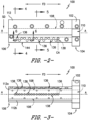
- a side view of nozzle 100 (with a die holder 114 removed) is provided in FIG. 2 and a bottom view is provided in FIG. 3 .
- nozzle 100 includes a main body 112 constructed by joining two portions 112a and 112b. Fastening devices such as e.g., threaded bolts (not shown) can be extended through apertures 142 to hold portions 112a and 112b together securely.
- Main body portions 112a and 112b may be fabricated from carbon steel that has been machined to create the features described herein. Other constructions and materials may be used for main body 112 as well.
- nozzle 100 On first end 104, nozzle 100 includes a mounting head 102 that may be used for connecting to an extrusion machine downstream of its screw (not shown), which is used to push material such as a rubber formulation through nozzle 100.
- An inlet 110 ( FIGS. 2 and 3 ) is defined by nozzle 100 at first end 104 and allows for the flow of material into an internal cavity 108 defined within main body 112 of nozzle 100.
- cavity 108 extends longitudinally along a first direction FD of main body 112 between first end 104 and second end 106.
- Second end 106 includes an opening or port 134 that can be used e.g., to clean out or flush material through nozzle 100. Port 134 can be plugged or otherwise closed during extrusion operations.
- a die holder 114 is attached to a bottom face 144 ( FIG. 2 ) of main body 112.
- Die holder 114 includes a slot 116 ( FIG. 1 ) into which a die or die plate 118 is received.
- die 118 extends along first direction FD.
- exemplary die 118 includes a plurality of die apertures 120 spaced apart along first direction FD and positioned adjacent to each other.
- the flow of material (arrow S) into nozzle 100 is extruded through apertures 120 (arrows F) under the pressure provided by the extrusion machine.
- the shape of the die apertures 120 is used to control the shape or profile of the extruded material.
- die 118 may be equipped with a single aperture configured to extrude rubber material in the shape of a tread profile.
- one problem with conventional extruders is that the flow of material along the die and through the aperture(s) may not be uniformly distributed across the width of the flow path (i.e. along first direction FD), leading to unacceptable profiles for the extruded material.
- the present invention provides adjustability in the flow across the width of the flow path (i.e. along first direction FD) in order to more accurately control the flow and obtain the desired profile of extruded material.
- main body 112 defines a plurality of channels 138 that are each connected with (i.e. in fluid communication with) cavity 108.
- Each channel 138 is shown in the bottom view of FIG. 3 while dashed lines are used to represent only one such channel 138 by way of example in FIG. 2 .
- Each channel has a channel axis CA that is oriented along a second direction, which is orthogonal to first direction FD and is parallel to the overall direction of material flow through each channel 138.
- the flow of material (arrow S) into cavity 108 passes into channels 138, which are positioned upstream of die apertures 120 in die 118.
- channels 138 are arranged adjacent to each other along first direction FD, are uniformly spaced along first direction FD, and are aligned in a linear manner along a central axis A-A of main body 112. If a sufficient volumetric flow of material is provided, the material will spread throughout cavity 108 to pass into all channels 138.
- Each pin 122 is associated with at least one channel 138 and is movable in and out of a respective channel 138 so as to selectively control the flow of material through the channel 138 based on the amount of channel obstruction.
- each channel 138 includes a channel inlet 146 and a channel outlet 148 that are upstream of die 118.
- a plurality of apertures 136 are defined along main body 112, with each aperture intersecting and connected with at least one channel 138. As best seen in FIG. 2 , a uniform spacing is used between adjacent apertures 136 for this exemplary embodiment.
- Each aperture 136 is shown in FIG. 2 while only one such aperture 136 is shown with dashed lines by way of example in FIG. 3 .
- pins 122 and apertures 136 are staggered with respect to each other along first direction FD.
- pins 122 and apertures 136 may be arranged e.g., linearly or aligned along first direction FD.
- Apertures 136 have an aperture axis SA oriented along a third direction TD, which is orthogonal to both first direction FD and second direction SD.
- Each aperture axis SA is also orthogonal to the overall direction of flow through a respective channel 138.
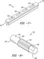
- each pin 122 is movable along the aperture axis SA in and out of aperture 136. Such movement controls the amount by which an interior end 130 of each pin 122 protrudes into each channel 138 to obstruct the flow of material there-through from cavity 108 under pressure from the extrusion machine. The amount of obstruction determines the volumetric flow rate of material through channel 138. Because pins 122 intersect each channel 138 along first direction FD, the entire width of flow from cavity 108 to die 118 can be controlled.
- each pin 122 can be independently controlled. More particularly, pins 122a and 122b are shown in different positions within their respective apertures 136 - resulting in different amount of material flowing through each respective channel 138. Nozzle 100 can thereby be used to more accurately control the full width (along first direction FD) of material flow to die 118 at multiple locations along the width of flow (i.e. along first direction FD) so as to ensure e.g., the desired profile of material is extruded through each die aperture 120 regardless of its position along first direction FD.
- Pin 138 is provided by way of example only. Other mechanisms may be used for manually or automatically adjusting the position of each pin 138 within aperture 136. For example, each pin could be configured with a solenoid or other actuator for automatic adjustment. Other mechanisms may be used as well.
- each channel 138 is shown with a channel axis CA oriented along a second direction orthogonal to a first direction. Flow through channels 138 is therefore perpendicular to the overall direction of flow S into nozzle 100.
- the nozzle may also be constructed so that the overall flow direction through the channels is parallel with the overall direction of flow S into the nozzle, the overall direction of flow through the nozzle cavity, or both.
Landscapes
- Engineering & Computer Science (AREA)
- Mechanical Engineering (AREA)
- Manufacturing & Machinery (AREA)
- Extrusion Moulding Of Plastics Or The Like (AREA)
Claims (10)
- Buse (100) de régulation de matière extrudée s'écoulant depuis une extrudeuse, comprenant :un corps principal (112) définissant une cavité (108) pour la réception de matière s'écoulant dans la buse (100) dans un premier sens (FD) ;une entrée (110) reliée à la cavité (108) de manière à permettre l'écoulement de matière extrudée dans la cavité (108) ;une pluralité de canaux (138) reliés à la cavité (108) pour permettre l'écoulement de matière extrudée hors de la cavité (108) et à travers chacun des canaux (138), la pluralité de canaux (138) étant agencés adjacents l'un à l'autre dans ledit premier sens (FD) de la buse (100), dans laquelle chaque canal (138) a un axe de canal (CA), et définit une sortie de canal (148) et un sens d'écoulement de matière à travers chaque canal (138) dans un deuxième sens (SD) qui est orthogonal au premier sens (FD) ; etune pluralité de tiges (122), chaque tige (122) étant associée à au moins un canal (138) et mobile vers l'intérieur et vers l'extérieur du canal (138) dans un troisième sens (TD) de sorte que l'écoulement de matière à travers chaque canal (138) puisse être ajusté sélectivement par la régulation de la quantité d'obstruction du canal (138) avec la tige (122), dans laquelle le troisième sens (TD) est orthogonal à la fois aux premier et deuxième sens (FD, SD) ;caractérisée en ce quela buse (100) comprend en outre une filière (118), et un porte-filière (114) et le porte-filière (114) est fixé au corps principal (112) et positionné en aval de la pluralité de canaux (138), dans laquelle ledit porte-filière (114) est configuré pour recevoir l'écoulement de matière extrudée depuis la pluralité de canaux (138) et le porte-filière (114) définit une fente (116) dans laquelle la filière (118) est reçue.
- Buse (100) selon la revendication 1, dans laquelle la pluralité de canaux (138) sont agencés linéairement dans le premier sens (FD) .
- Buse (100) selon la revendication 1, comprenant en outre une pluralité d'ouvertures (136) positionnées le long du corps principal (112), chaque ouverture (136) recevant l'une des tiges (122), les tiges (122) étant mobiles à l'intérieur des ouvertures (136), dans laquelle les ouvertures (136) sont reliées aux canaux (138).
- Buse (100) selon la revendication 1, comprenant en outre une pluralité d'ouvertures filetées (136) définies par le corps principal (112) et positionnées adjacentes l'une à l'autre dans le premier sens (FD), dans laquelle la pluralité de tiges (122) sont configurées avec des filetages (140) pour une réception complémentaire dans la pluralité d'ouvertures filetées (136) de sorte qu'une rotation des tiges (122) puisse être utilisée pour réguler le déplacement des tiges (122) vers l'intérieur et vers l'extérieur des canaux (138) et le long des ouvertures (136) .
- Buse (100) selon la revendication 1, comprenant en outre une pluralité d'ouvertures (136) le long du corps principal (112), chaque ouverture (136) recevant l'une des tiges (122), dans laquelle chaque tige (122) est mobile vers l'intérieur et vers l'extérieur d'au moins l'une des ouvertures (136) le long d'un axe d'ouverture (SA) qui est orthogonal à un sens d'écoulement de matière à travers les canaux (138).
- Buse (100) selon la revendication 1, comprenant en outre une pluralité d'ouvertures (136) positionnées le long du corps principal (112), chaque ouverture (136) recevant l'une des tiges (122), dans laquelle les ouvertures (136) sont reliées aux canaux (138) et sont décalées l'une par rapport à l'autre dans le premier sens (FD).
- Buse (100) selon la revendication 1, comprenant en outre une pluralité d'ouvertures (136) positionnées le long du corps principal (112), chaque ouverture (136) recevant l'une des tiges (122), dans laquelle les ouvertures (136) sont reliées aux canaux (138) et sont agencées linéairement dans le premier sens (FD).
- Buse (100) selon la revendication 1, dans laquelle la pluralité de canaux (138) sont espacés uniformément dans le premier sens (FD).
- Buse (100) selon la revendication 1, comprenant en outre une tête de montage (102) fixée au corps principal (112).
- Buse (100) selon la revendication 1, comprenant en outre la filière (118) fixée au porte-filière (114) et définissant une ouverture de filière (120) pour l'écoulement de matière hors de la buse (100).
Applications Claiming Priority (1)
| Application Number | Priority Date | Filing Date | Title |
|---|---|---|---|
| PCT/US2014/058235 WO2016053286A1 (fr) | 2014-09-30 | 2014-09-30 | Buse pour une extrudeuse avec contrôle de flux |
Publications (3)
| Publication Number | Publication Date |
|---|---|
| EP3200964A1 EP3200964A1 (fr) | 2017-08-09 |
| EP3200964A4 EP3200964A4 (fr) | 2018-05-23 |
| EP3200964B1 true EP3200964B1 (fr) | 2023-09-27 |
Family
ID=55631142
Family Applications (1)
| Application Number | Title | Priority Date | Filing Date |
|---|---|---|---|
| EP14903319.3A Active EP3200964B1 (fr) | 2014-09-30 | 2014-09-30 | Buse pour une extrudeuse avec contrôle de flux |
Country Status (4)
| Country | Link |
|---|---|
| US (1) | US20170246788A1 (fr) |
| EP (1) | EP3200964B1 (fr) |
| CN (1) | CN107073787A (fr) |
| WO (1) | WO2016053286A1 (fr) |
Families Citing this family (2)
| Publication number | Priority date | Publication date | Assignee | Title |
|---|---|---|---|---|
| CN108454062A (zh) * | 2017-12-23 | 2018-08-28 | 安徽耐科挤出科技股份有限公司 | 装饰板定型模型腔尺寸在线调节机构 |
| IT201800002860A1 (it) * | 2018-02-20 | 2019-08-20 | Colmec S P A | Mescolatore-estrusore bivite, comprendente mezzi di controllo di una camera di rimescolamento |
Family Cites Families (10)
| Publication number | Priority date | Publication date | Assignee | Title |
|---|---|---|---|---|
| US3559239A (en) * | 1968-02-27 | 1971-02-02 | American Can Co | Multilayer extrusion die |
| US3734662A (en) * | 1971-02-08 | 1973-05-22 | Black Clawson Co | Flat film plastic extrusion apparatus |
| DE3929002A1 (de) * | 1989-09-01 | 1991-03-14 | Schmidt Erwepa Maschf | Vorrichtung zum extrudieren von kunststoff-mehrschichtfolien oder -platten |
| US5674440A (en) * | 1995-05-05 | 1997-10-07 | Graham Engineering Corporation | Die head with adjustable mandrel and method |
| US6251452B1 (en) * | 1999-04-23 | 2001-06-26 | General Mills, Inc. | Apparatus and methods for making multiple, complexly patterned extrudates |
| US6733263B2 (en) * | 2001-04-13 | 2004-05-11 | Hills Pet Nutrition Inc. | Composition, process and apparatus |
| WO2003004246A1 (fr) * | 2001-07-05 | 2003-01-16 | J.R. Simplot Company | Systeme d'extrusion multi-voies |
| US7056112B2 (en) * | 2003-06-02 | 2006-06-06 | Extrusion Dies Industries, Llc | Extrusion die and method for using the same |
| EP2507029B1 (fr) * | 2009-12-04 | 2014-02-26 | Shell Internationale Research Maatschappij B.V. | Procédé pour préparer des unités de liant enrobées |
| CN201736429U (zh) * | 2010-06-18 | 2011-02-09 | 四川省资阳市雅之江塑业有限公司 | 打包带一出二坯料口模装置 |
-
2014
- 2014-09-30 CN CN201480082008.5A patent/CN107073787A/zh active Pending
- 2014-09-30 EP EP14903319.3A patent/EP3200964B1/fr active Active
- 2014-09-30 US US15/508,623 patent/US20170246788A1/en not_active Abandoned
- 2014-09-30 WO PCT/US2014/058235 patent/WO2016053286A1/fr not_active Ceased
Also Published As
| Publication number | Publication date |
|---|---|
| WO2016053286A1 (fr) | 2016-04-07 |
| CN107073787A (zh) | 2017-08-18 |
| EP3200964A1 (fr) | 2017-08-09 |
| EP3200964A4 (fr) | 2018-05-23 |
| US20170246788A1 (en) | 2017-08-31 |
Similar Documents
| Publication | Publication Date | Title |
|---|---|---|
| EP2862693B1 (fr) | Bloc d'entraînement de coextrusion et ensemble d'insert de profilage de coextrusion | |
| KR102502584B1 (ko) | 타이어들을 위한 트레드 및/또는 측면 스트립들을 생산하기 위한 타이어 스트립 압출 장치, 및 타이어의 트레드 또는 측면 스트립을 생산하기 위한 방법 | |
| EP2801467B1 (fr) | Dispositif d'étalonnage pour l'étalonnage d'un tuyau de film extrudé | |
| US8777605B2 (en) | Deckle technology | |
| EP2435155A1 (fr) | Appareil de filtration pour filtrer un fluide et ses procédés d'utilisation | |
| EP3200964B1 (fr) | Buse pour une extrudeuse avec contrôle de flux | |
| AT412769B (de) | Formgebungseinrichtung für eine extrusionsanlage | |
| KR102091064B1 (ko) | 고무 압출 장치 및 고무 압출물의 제조 방법 | |
| JP2006518294A (ja) | 押出成形品の反り矯正装置および方法 | |
| US11485047B2 (en) | Extrusion facility comprising an improved extrusion head | |
| US6821106B1 (en) | Roller die preformer for wide extrusions | |
| EP1134066A2 (fr) | Bloc d'alimentation pour l'ajustement de dimensions d'un ensemble de couches coextrudées d'un film multicouche | |
| US20160075073A1 (en) | Flow controlled strand die | |
| EP2282846B1 (fr) | Buse à large fente | |
| JP6945084B2 (ja) | 少なくとも1つの有孔板を有する押出装置 | |
| CN110114201B (zh) | 包括改进的挤出头的挤出设备 | |
| US6814315B2 (en) | Liquid dispensing manifold with adjustable slide plate | |
| EP0595198B1 (fr) | Appareil et méthode pour la fabrication de profilés allongés en matières plastiques | |
| EP1902787B1 (fr) | Appareil d'application de produit fluide, en particulier d'adhésif thermofusible | |
| SE420692B (sv) | Anordning for samextrudering av termoplastlaminat | |
| EP3287254B1 (fr) | Structure de mélangeur pour un outil pour film et outil pour film | |
| JP6538327B2 (ja) | デッケルシステムを備える押出ダイ及びその使用方法 | |
| EP3153296B1 (fr) | Tête d'extrusion pour un dispositif de fabrication d'un tuyau composite | |
| CN108068196B (zh) | 一种复合型挤出模头 | |
| DE4416010C2 (de) | Ventilspindelanordnung für die Schmelzeleitung einer Plastifiziereinheit zur kontinuierlichen Kunststoffverarbeitung |
Legal Events
| Date | Code | Title | Description |
|---|---|---|---|
| STAA | Information on the status of an ep patent application or granted ep patent |
Free format text: STATUS: THE INTERNATIONAL PUBLICATION HAS BEEN MADE |
|
| PUAI | Public reference made under article 153(3) epc to a published international application that has entered the european phase |
Free format text: ORIGINAL CODE: 0009012 |
|
| STAA | Information on the status of an ep patent application or granted ep patent |
Free format text: STATUS: REQUEST FOR EXAMINATION WAS MADE |
|
| 17P | Request for examination filed |
Effective date: 20170308 |
|
| AK | Designated contracting states |
Kind code of ref document: A1 Designated state(s): AL AT BE BG CH CY CZ DE DK EE ES FI FR GB GR HR HU IE IS IT LI LT LU LV MC MK MT NL NO PL PT RO RS SE SI SK SM TR |
|
| AX | Request for extension of the european patent |
Extension state: BA ME |
|
| DAX | Request for extension of the european patent (deleted) | ||
| A4 | Supplementary search report drawn up and despatched |
Effective date: 20180424 |
|
| RIC1 | Information provided on ipc code assigned before grant |
Ipc: B29C 47/08 20060101AFI20180418BHEP Ipc: B29C 47/92 20060101ALI20180418BHEP Ipc: B29C 47/30 20060101ALI20180418BHEP Ipc: B29C 47/06 20060101ALN20180418BHEP |
|
| RAP1 | Party data changed (applicant data changed or rights of an application transferred) |
Owner name: COMPAGNIE GENERALE DES ETABLISSEMENTS MICHELIN |
|
| GRAP | Despatch of communication of intention to grant a patent |
Free format text: ORIGINAL CODE: EPIDOSNIGR1 |
|
| STAA | Information on the status of an ep patent application or granted ep patent |
Free format text: STATUS: GRANT OF PATENT IS INTENDED |
|
| RIC1 | Information provided on ipc code assigned before grant |
Ipc: B29C 48/92 20190101ALI20191202BHEP Ipc: B29C 48/21 20190101ALN20191202BHEP Ipc: B29C 48/345 20190101ALI20191202BHEP Ipc: B29C 48/255 20190101AFI20191202BHEP |
|
| INTG | Intention to grant announced |
Effective date: 20191220 |
|
| RIC1 | Information provided on ipc code assigned before grant |
Ipc: B29C 48/21 20190101ALN20191209BHEP Ipc: B29C 48/92 20190101ALI20191209BHEP Ipc: B29C 48/255 20190101AFI20191209BHEP Ipc: B29C 48/345 20190101ALI20191209BHEP |
|
| GRAJ | Information related to disapproval of communication of intention to grant by the applicant or resumption of examination proceedings by the epo deleted |
Free format text: ORIGINAL CODE: EPIDOSDIGR1 |
|
| STAA | Information on the status of an ep patent application or granted ep patent |
Free format text: STATUS: REQUEST FOR EXAMINATION WAS MADE |
|
| INTC | Intention to grant announced (deleted) | ||
| STAA | Information on the status of an ep patent application or granted ep patent |
Free format text: STATUS: EXAMINATION IS IN PROGRESS |
|
| 17Q | First examination report despatched |
Effective date: 20200707 |
|
| REG | Reference to a national code |
Ref country code: DE Ref legal event code: R079 Free format text: PREVIOUS MAIN CLASS: B29C0047300000 Ipc: B29C0048255000 Ref country code: DE Ref legal event code: R079 Ref document number: 602014088449 Country of ref document: DE Free format text: PREVIOUS MAIN CLASS: B29C0047300000 Ipc: B29C0048255000 |
|
| GRAP | Despatch of communication of intention to grant a patent |
Free format text: ORIGINAL CODE: EPIDOSNIGR1 |
|
| STAA | Information on the status of an ep patent application or granted ep patent |
Free format text: STATUS: GRANT OF PATENT IS INTENDED |
|
| RIC1 | Information provided on ipc code assigned before grant |
Ipc: B29C 48/21 20190101ALN20230425BHEP Ipc: B29C 48/92 20190101ALI20230425BHEP Ipc: B29C 48/345 20190101ALI20230425BHEP Ipc: B29C 48/255 20190101AFI20230425BHEP |
|
| INTG | Intention to grant announced |
Effective date: 20230511 |
|
| GRAS | Grant fee paid |
Free format text: ORIGINAL CODE: EPIDOSNIGR3 |
|
| GRAA | (expected) grant |
Free format text: ORIGINAL CODE: 0009210 |
|
| STAA | Information on the status of an ep patent application or granted ep patent |
Free format text: STATUS: THE PATENT HAS BEEN GRANTED |
|
| AK | Designated contracting states |
Kind code of ref document: B1 Designated state(s): AL AT BE BG CH CY CZ DE DK EE ES FI FR GB GR HR HU IE IS IT LI LT LU LV MC MK MT NL NO PL PT RO RS SE SI SK SM TR |
|
| REG | Reference to a national code |
Ref country code: GB Ref legal event code: FG4D |
|
| REG | Reference to a national code |
Ref country code: CH Ref legal event code: EP |
|
| REG | Reference to a national code |
Ref country code: DE Ref legal event code: R096 Ref document number: 602014088449 Country of ref document: DE |
|
| REG | Reference to a national code |
Ref country code: IE Ref legal event code: FG4D |
|
| REG | Reference to a national code |
Ref country code: LT Ref legal event code: MG9D |
|
| PG25 | Lapsed in a contracting state [announced via postgrant information from national office to epo] |
Ref country code: GR Free format text: LAPSE BECAUSE OF FAILURE TO SUBMIT A TRANSLATION OF THE DESCRIPTION OR TO PAY THE FEE WITHIN THE PRESCRIBED TIME-LIMIT Effective date: 20231228 |
|
| PG25 | Lapsed in a contracting state [announced via postgrant information from national office to epo] |
Ref country code: SE Free format text: LAPSE BECAUSE OF FAILURE TO SUBMIT A TRANSLATION OF THE DESCRIPTION OR TO PAY THE FEE WITHIN THE PRESCRIBED TIME-LIMIT Effective date: 20230927 Ref country code: RS Free format text: LAPSE BECAUSE OF FAILURE TO SUBMIT A TRANSLATION OF THE DESCRIPTION OR TO PAY THE FEE WITHIN THE PRESCRIBED TIME-LIMIT Effective date: 20230927 Ref country code: NO Free format text: LAPSE BECAUSE OF FAILURE TO SUBMIT A TRANSLATION OF THE DESCRIPTION OR TO PAY THE FEE WITHIN THE PRESCRIBED TIME-LIMIT Effective date: 20231227 Ref country code: LV Free format text: LAPSE BECAUSE OF FAILURE TO SUBMIT A TRANSLATION OF THE DESCRIPTION OR TO PAY THE FEE WITHIN THE PRESCRIBED TIME-LIMIT Effective date: 20230927 Ref country code: LT Free format text: LAPSE BECAUSE OF FAILURE TO SUBMIT A TRANSLATION OF THE DESCRIPTION OR TO PAY THE FEE WITHIN THE PRESCRIBED TIME-LIMIT Effective date: 20230927 Ref country code: GR Free format text: LAPSE BECAUSE OF FAILURE TO SUBMIT A TRANSLATION OF THE DESCRIPTION OR TO PAY THE FEE WITHIN THE PRESCRIBED TIME-LIMIT Effective date: 20231228 Ref country code: FI Free format text: LAPSE BECAUSE OF FAILURE TO SUBMIT A TRANSLATION OF THE DESCRIPTION OR TO PAY THE FEE WITHIN THE PRESCRIBED TIME-LIMIT Effective date: 20230927 |
|
| REG | Reference to a national code |
Ref country code: NL Ref legal event code: MP Effective date: 20230927 |
|
| REG | Reference to a national code |
Ref country code: AT Ref legal event code: MK05 Ref document number: 1614970 Country of ref document: AT Kind code of ref document: T Effective date: 20230927 |
|
| PG25 | Lapsed in a contracting state [announced via postgrant information from national office to epo] |
Ref country code: NL Free format text: LAPSE BECAUSE OF FAILURE TO SUBMIT A TRANSLATION OF THE DESCRIPTION OR TO PAY THE FEE WITHIN THE PRESCRIBED TIME-LIMIT Effective date: 20230927 |
|
| PG25 | Lapsed in a contracting state [announced via postgrant information from national office to epo] |
Ref country code: IS Free format text: LAPSE BECAUSE OF FAILURE TO SUBMIT A TRANSLATION OF THE DESCRIPTION OR TO PAY THE FEE WITHIN THE PRESCRIBED TIME-LIMIT Effective date: 20240127 |
|
| PG25 | Lapsed in a contracting state [announced via postgrant information from national office to epo] |
Ref country code: AT Free format text: LAPSE BECAUSE OF FAILURE TO SUBMIT A TRANSLATION OF THE DESCRIPTION OR TO PAY THE FEE WITHIN THE PRESCRIBED TIME-LIMIT Effective date: 20230927 |
|
| PG25 | Lapsed in a contracting state [announced via postgrant information from national office to epo] |
Ref country code: ES Free format text: LAPSE BECAUSE OF FAILURE TO SUBMIT A TRANSLATION OF THE DESCRIPTION OR TO PAY THE FEE WITHIN THE PRESCRIBED TIME-LIMIT Effective date: 20230927 |
|
| PG25 | Lapsed in a contracting state [announced via postgrant information from national office to epo] |
Ref country code: SM Free format text: LAPSE BECAUSE OF FAILURE TO SUBMIT A TRANSLATION OF THE DESCRIPTION OR TO PAY THE FEE WITHIN THE PRESCRIBED TIME-LIMIT Effective date: 20230927 Ref country code: RO Free format text: LAPSE BECAUSE OF FAILURE TO SUBMIT A TRANSLATION OF THE DESCRIPTION OR TO PAY THE FEE WITHIN THE PRESCRIBED TIME-LIMIT Effective date: 20230927 Ref country code: IS Free format text: LAPSE BECAUSE OF FAILURE TO SUBMIT A TRANSLATION OF THE DESCRIPTION OR TO PAY THE FEE WITHIN THE PRESCRIBED TIME-LIMIT Effective date: 20240127 Ref country code: ES Free format text: LAPSE BECAUSE OF FAILURE TO SUBMIT A TRANSLATION OF THE DESCRIPTION OR TO PAY THE FEE WITHIN THE PRESCRIBED TIME-LIMIT Effective date: 20230927 Ref country code: EE Free format text: LAPSE BECAUSE OF FAILURE TO SUBMIT A TRANSLATION OF THE DESCRIPTION OR TO PAY THE FEE WITHIN THE PRESCRIBED TIME-LIMIT Effective date: 20230927 Ref country code: CZ Free format text: LAPSE BECAUSE OF FAILURE TO SUBMIT A TRANSLATION OF THE DESCRIPTION OR TO PAY THE FEE WITHIN THE PRESCRIBED TIME-LIMIT Effective date: 20230927 Ref country code: AT Free format text: LAPSE BECAUSE OF FAILURE TO SUBMIT A TRANSLATION OF THE DESCRIPTION OR TO PAY THE FEE WITHIN THE PRESCRIBED TIME-LIMIT Effective date: 20230927 Ref country code: SK Free format text: LAPSE BECAUSE OF FAILURE TO SUBMIT A TRANSLATION OF THE DESCRIPTION OR TO PAY THE FEE WITHIN THE PRESCRIBED TIME-LIMIT Effective date: 20230927 Ref country code: PT Free format text: LAPSE BECAUSE OF FAILURE TO SUBMIT A TRANSLATION OF THE DESCRIPTION OR TO PAY THE FEE WITHIN THE PRESCRIBED TIME-LIMIT Effective date: 20240129 |
|
| REG | Reference to a national code |
Ref country code: CH Ref legal event code: PL |
|
| PG25 | Lapsed in a contracting state [announced via postgrant information from national office to epo] |
Ref country code: LU Free format text: LAPSE BECAUSE OF NON-PAYMENT OF DUE FEES Effective date: 20230930 |
|
| REG | Reference to a national code |
Ref country code: BE Ref legal event code: MM Effective date: 20230930 |
|
| PG25 | Lapsed in a contracting state [announced via postgrant information from national office to epo] |
Ref country code: PL Free format text: LAPSE BECAUSE OF FAILURE TO SUBMIT A TRANSLATION OF THE DESCRIPTION OR TO PAY THE FEE WITHIN THE PRESCRIBED TIME-LIMIT Effective date: 20230927 Ref country code: LU Free format text: LAPSE BECAUSE OF NON-PAYMENT OF DUE FEES Effective date: 20230930 Ref country code: IT Free format text: LAPSE BECAUSE OF FAILURE TO SUBMIT A TRANSLATION OF THE DESCRIPTION OR TO PAY THE FEE WITHIN THE PRESCRIBED TIME-LIMIT Effective date: 20230927 |
|
| REG | Reference to a national code |
Ref country code: DE Ref legal event code: R097 Ref document number: 602014088449 Country of ref document: DE |
|
| PG25 | Lapsed in a contracting state [announced via postgrant information from national office to epo] |
Ref country code: MC Free format text: LAPSE BECAUSE OF FAILURE TO SUBMIT A TRANSLATION OF THE DESCRIPTION OR TO PAY THE FEE WITHIN THE PRESCRIBED TIME-LIMIT Effective date: 20230927 |
|
| REG | Reference to a national code |
Ref country code: IE Ref legal event code: MM4A |
|
| PG25 | Lapsed in a contracting state [announced via postgrant information from national office to epo] |
Ref country code: IE Free format text: LAPSE BECAUSE OF NON-PAYMENT OF DUE FEES Effective date: 20230930 |
|
| PG25 | Lapsed in a contracting state [announced via postgrant information from national office to epo] |
Ref country code: DK Free format text: LAPSE BECAUSE OF FAILURE TO SUBMIT A TRANSLATION OF THE DESCRIPTION OR TO PAY THE FEE WITHIN THE PRESCRIBED TIME-LIMIT Effective date: 20230927 |
|
| PG25 | Lapsed in a contracting state [announced via postgrant information from national office to epo] |
Ref country code: CH Free format text: LAPSE BECAUSE OF NON-PAYMENT OF DUE FEES Effective date: 20230930 |
|
| PG25 | Lapsed in a contracting state [announced via postgrant information from national office to epo] |
Ref country code: MC Free format text: LAPSE BECAUSE OF FAILURE TO SUBMIT A TRANSLATION OF THE DESCRIPTION OR TO PAY THE FEE WITHIN THE PRESCRIBED TIME-LIMIT Effective date: 20230927 Ref country code: IE Free format text: LAPSE BECAUSE OF NON-PAYMENT OF DUE FEES Effective date: 20230930 Ref country code: DK Free format text: LAPSE BECAUSE OF FAILURE TO SUBMIT A TRANSLATION OF THE DESCRIPTION OR TO PAY THE FEE WITHIN THE PRESCRIBED TIME-LIMIT Effective date: 20230927 Ref country code: CH Free format text: LAPSE BECAUSE OF NON-PAYMENT OF DUE FEES Effective date: 20230930 |
|
| PLBE | No opposition filed within time limit |
Free format text: ORIGINAL CODE: 0009261 |
|
| STAA | Information on the status of an ep patent application or granted ep patent |
Free format text: STATUS: NO OPPOSITION FILED WITHIN TIME LIMIT |
|
| GBPC | Gb: european patent ceased through non-payment of renewal fee |
Effective date: 20231227 |
|
| PG25 | Lapsed in a contracting state [announced via postgrant information from national office to epo] |
Ref country code: BE Free format text: LAPSE BECAUSE OF NON-PAYMENT OF DUE FEES Effective date: 20230930 |
|
| 26N | No opposition filed |
Effective date: 20240628 |
|
| PG25 | Lapsed in a contracting state [announced via postgrant information from national office to epo] |
Ref country code: GB Free format text: LAPSE BECAUSE OF NON-PAYMENT OF DUE FEES Effective date: 20231227 |
|
| PG25 | Lapsed in a contracting state [announced via postgrant information from national office to epo] |
Ref country code: SI Free format text: LAPSE BECAUSE OF FAILURE TO SUBMIT A TRANSLATION OF THE DESCRIPTION OR TO PAY THE FEE WITHIN THE PRESCRIBED TIME-LIMIT Effective date: 20230927 |
|
| PG25 | Lapsed in a contracting state [announced via postgrant information from national office to epo] |
Ref country code: SI Free format text: LAPSE BECAUSE OF FAILURE TO SUBMIT A TRANSLATION OF THE DESCRIPTION OR TO PAY THE FEE WITHIN THE PRESCRIBED TIME-LIMIT Effective date: 20230927 Ref country code: GB Free format text: LAPSE BECAUSE OF NON-PAYMENT OF DUE FEES Effective date: 20231227 |
|
| PG25 | Lapsed in a contracting state [announced via postgrant information from national office to epo] |
Ref country code: BG Free format text: LAPSE BECAUSE OF FAILURE TO SUBMIT A TRANSLATION OF THE DESCRIPTION OR TO PAY THE FEE WITHIN THE PRESCRIBED TIME-LIMIT Effective date: 20230927 |
|
| PG25 | Lapsed in a contracting state [announced via postgrant information from national office to epo] |
Ref country code: BG Free format text: LAPSE BECAUSE OF FAILURE TO SUBMIT A TRANSLATION OF THE DESCRIPTION OR TO PAY THE FEE WITHIN THE PRESCRIBED TIME-LIMIT Effective date: 20230927 |
|
| PG25 | Lapsed in a contracting state [announced via postgrant information from national office to epo] |
Ref country code: HR Free format text: LAPSE BECAUSE OF FAILURE TO SUBMIT A TRANSLATION OF THE DESCRIPTION OR TO PAY THE FEE WITHIN THE PRESCRIBED TIME-LIMIT Effective date: 20230927 |
|
| PG25 | Lapsed in a contracting state [announced via postgrant information from national office to epo] |
Ref country code: CY Free format text: LAPSE BECAUSE OF FAILURE TO SUBMIT A TRANSLATION OF THE DESCRIPTION OR TO PAY THE FEE WITHIN THE PRESCRIBED TIME-LIMIT; INVALID AB INITIO Effective date: 20140930 |
|
| PG25 | Lapsed in a contracting state [announced via postgrant information from national office to epo] |
Ref country code: HU Free format text: LAPSE BECAUSE OF FAILURE TO SUBMIT A TRANSLATION OF THE DESCRIPTION OR TO PAY THE FEE WITHIN THE PRESCRIBED TIME-LIMIT; INVALID AB INITIO Effective date: 20140930 |
|
| PGFP | Annual fee paid to national office [announced via postgrant information from national office to epo] |
Ref country code: DE Payment date: 20250919 Year of fee payment: 12 |
|
| PGFP | Annual fee paid to national office [announced via postgrant information from national office to epo] |
Ref country code: FR Payment date: 20250922 Year of fee payment: 12 |
|
| PG25 | Lapsed in a contracting state [announced via postgrant information from national office to epo] |
Ref country code: TR Free format text: LAPSE BECAUSE OF FAILURE TO SUBMIT A TRANSLATION OF THE DESCRIPTION OR TO PAY THE FEE WITHIN THE PRESCRIBED TIME-LIMIT Effective date: 20230927 |