EP2282846B1 - Buse à large fente - Google Patents
Buse à large fente Download PDFInfo
- Publication number
- EP2282846B1 EP2282846B1 EP09753950.6A EP09753950A EP2282846B1 EP 2282846 B1 EP2282846 B1 EP 2282846B1 EP 09753950 A EP09753950 A EP 09753950A EP 2282846 B1 EP2282846 B1 EP 2282846B1
- Authority
- EP
- European Patent Office
- Prior art keywords
- tube
- medium
- slot
- discharge nozzle
- housing
- Prior art date
- Legal status (The legal status is an assumption and is not a legal conclusion. Google has not performed a legal analysis and makes no representation as to the accuracy of the status listed.)
- Not-in-force
Links
Images



Classifications
-
- B—PERFORMING OPERATIONS; TRANSPORTING
- B05—SPRAYING OR ATOMISING IN GENERAL; APPLYING FLUENT MATERIALS TO SURFACES, IN GENERAL
- B05C—APPARATUS FOR APPLYING FLUENT MATERIALS TO SURFACES, IN GENERAL
- B05C5/00—Apparatus in which liquid or other fluent material is projected, poured or allowed to flow on to the surface of the work
- B05C5/02—Apparatus in which liquid or other fluent material is projected, poured or allowed to flow on to the surface of the work the liquid or other fluent material being discharged through an outlet orifice by pressure, e.g. from an outlet device in contact or almost in contact, with the work
- B05C5/0254—Coating heads with slot-shaped outlet
- B05C5/0258—Coating heads with slot-shaped outlet flow controlled, e.g. by a valve
-
- B—PERFORMING OPERATIONS; TRANSPORTING
- B05—SPRAYING OR ATOMISING IN GENERAL; APPLYING FLUENT MATERIALS TO SURFACES, IN GENERAL
- B05C—APPARATUS FOR APPLYING FLUENT MATERIALS TO SURFACES, IN GENERAL
- B05C5/00—Apparatus in which liquid or other fluent material is projected, poured or allowed to flow on to the surface of the work
- B05C5/02—Apparatus in which liquid or other fluent material is projected, poured or allowed to flow on to the surface of the work the liquid or other fluent material being discharged through an outlet orifice by pressure, e.g. from an outlet device in contact or almost in contact, with the work
- B05C5/0225—Apparatus in which liquid or other fluent material is projected, poured or allowed to flow on to the surface of the work the liquid or other fluent material being discharged through an outlet orifice by pressure, e.g. from an outlet device in contact or almost in contact, with the work characterised by flow controlling means, e.g. valves, located proximate the outlet
- B05C5/0229—Apparatus in which liquid or other fluent material is projected, poured or allowed to flow on to the surface of the work the liquid or other fluent material being discharged through an outlet orifice by pressure, e.g. from an outlet device in contact or almost in contact, with the work characterised by flow controlling means, e.g. valves, located proximate the outlet the valve being a gate valve or a sliding valve
- B05C5/0233—Apparatus in which liquid or other fluent material is projected, poured or allowed to flow on to the surface of the work the liquid or other fluent material being discharged through an outlet orifice by pressure, e.g. from an outlet device in contact or almost in contact, with the work characterised by flow controlling means, e.g. valves, located proximate the outlet the valve being a gate valve or a sliding valve rotating valve, e.g. rotating perforated cylinder
Definitions
- the invention relates to a device according to the preamble of claim 1.
- Such a device describes the US 2006/01639 A1 ,
- the device has a housing with an elongate outlet nozzle. Within the housing there is a designed as a cylindrical tube medium distributor.
- the tube has on its lateral surface a circumferentially extending slot which passes at a rotation of the tube at the outlet nozzle.
- the device is able to apply an adhesive bead on a surface, wherein the course of the adhesive bead corresponds to the slot profile of the medium distributor.
- the GB 1 169 973 A describes a device for the surface delivery of an adhesive in which an inner tube is inserted in an outer tube. Both tubes have superimposed outlet slots.
- the DE 10216 356 C1 describes a device for dispensing a liquid medium, in which a rotational body is rotatably mounted within a housing.
- the housing and the rotary body have slots.
- the DE 103 06 884 B3 discloses an applicator head for applying liquid media with a rotary valve closure.
- a device in which a tubular medium distributor is mounted in a two-part housing with a slot extending in the axial direction of the tube.
- the tube having a circular cross-section is rotatably mounted in a congruent inner cylinder.
- the two housing parts each form two halves of the inner cylinder, wherein a lower housing part has an outlet slot which is flanked by two outlet lips.
- the lower housing part has a along in the region of the inner cylinder the edge of the exit slot extending recess with a wedge-shaped tapered bottom.
- the DE 197 57 237 C2 describes a device in which a longitudinal slot is in a substantially rectangular housing, which forms an over almost the entire length of the housing extending outlet nozzle.
- a roller with a helical groove extending on the roller surface slot.
- a flowable medium which may be a liquefied thermoplastic or a molten hot melt adhesive.
- the roll surface lies in sealing engagement with a bottom surface of the housing in which the outlet nozzle formed by a longitudinal slot is located.
- the helical slot of the medium distributor thus crosses the outlet nozzle at a plurality of spaced-apart locations. At these intersections, the flowable medium can escape from the outlet nozzle. If the medium distributor is rotated, this exit point migrates further in the nozzle extension direction. With the rotary application head described there, separate adhesive threads can be applied to a flat workpiece surface.
- the invention has the object of developing a generic device such that low to medium-viscosity media closed area on a flat workpiece surface can be applied, the mass flow of the medium is precisely on and off.
- the counter-sealing surfaces do not come from the housing, but from one in a recess of the housing Sealing strip are formed with a slot aligned with the outlet nozzle.
- a high sealing effect can be achieved, in particular by targeted application of a local pressure, so that the mass flow can be precisely switched on and off.
- the interior of the tube forms a reservoir which can be fed with a medium from a feed opening.
- the tube has a slot. This runs in such a way that it can be brought from an open position into a closed position by rotating the tube. In the open position, a passage opening which is open essentially over the entire length of the outlet opening forms from the reservoir to the outlet nozzle. In the closed position, this passage opening is completely closed.
- the housing is preferably formed by a half-tube.
- This half pipe runs centrally the outlet nozzle.
- the half tube forms a shell which receives the medium distributor.
- the half pipe also forms the arranged in the region of the outlet nozzle sealing strip.
- the material thickness of the sealing strip is preferably greater than the depth of the recess, so that the sealing strip protrudes like a socket from the recess.
- the inner wall of the housing thus has a distance from the outer wall of the medium distributor.
- the width of the sealing strip is limited to the immediate apex area of the tube.
- the sealing surfaces formed by the sealing strip run on a cylinder inner surface.
- the sealing strip forms sealing surfaces adapted to the outer wall of the pipe forming the medium distributor.
- the medium distributor against these sealing surfaces of the medium distributor is pressed with An horriliax, so that in the closed position no medium can escape from the reservoir. If the medium distributor is rotated into the open position, the medium can flow through the slot of the tube and the slot of the sealing strip into the slot forming the outlet nozzle in order to emerge uniformly from the outlet nozzle.
- To increase the stability of the slot of the sealing strip may be interrupted by a plurality of webs. The webs are spaced apart, wherein the distance between the webs corresponds to at least ten times the slot width. Measured in the extension direction of the outlet nozzle Length of the webs corresponds approximately to the slot width.
- the medium distributor has a substantially circular cross-sectional contour.
- the feed opening lies in the center of rotation of the medium distributor.
- the two ends of the half-tube are connected to headers, which slide the bearing plugs.
- the half tube may consist of two quarter tubes, which are connected to each other by means of the two head pieces but also with the help of the sealing strip and in particular glued.
- the pipe forming the medium distributor can be axially slotted over the entire length.
- the front ends of the tube can be glued to the bearing plug.
- the slot die according to the invention allows the application of low to medium-viscosity media and consists essentially of a slotted tube, which simultaneously forms a material reservoir. This tube has one or two side ports for media supply.
- the outlet nozzle forms the mating contour to the slot of the roller.
- the sealing strip has two mutually spaced by a slot sealing surfaces, which abut sealingly adjacent to the slot outer wall sections of the tube.
- the sealing strip thus lies between the slotted roller and the outlet nozzle.
- the material reservoir is dimensioned so that a uniform pressure prevails in the slotted hollow cylinder, preferably of the order of magnitude of 0.5 to 6 bar. This ensures that even with larger application widths, in particular from 500 mm to 1000 mm, uniform media application takes place.
- the connection of the reservoir is released to the outlet nozzle. This enables both a defined start of application and a defined end of application.
- structured coatings can be applied to surfaces of workpieces.
- the device With the device also vertical surfaces can be coated. It is even possible to work overhead with the nozzle. For this purpose, prove the radially projecting, the outlet nozzle flanking lips as beneficial.
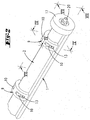
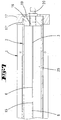
- a housing 1 provided in the form of a half-pipe.
- This shell-like housing 1 forms the nozzle carrier.
- the shell which extends approximately over a semicircle, has in its center a longitudinal slot which forms an outlet nozzle 4.
- the longitudinal slot extends over the entire length of the half pipe 1, so that the half pipe 1 is composed of two quarter pipe sections.
- the two front ends of the half tube 1 are connected to head pieces 24 and 17, respectively.
- the head pieces 17,24 form essentially cylindrical bodies and a bearing recess 17 ', 24'.
- the inner wall of the half tube 1 has a recess 7 having the shape of a rectangular groove.
- this recess 7 there is a sealing strip 3.
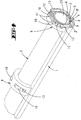
- the sealing strip 3 extends essentially over the entire length of the half tube 1 and has a longitudinally extending, central slot.
- the slot 5 is aligned with the outlet nozzle 4.
- the material thickness the sealing strip 3 is larger than the depth of the recess 7, so that the counter portion 3 'forming head portion of the sealing strip 3 protrudes like a socket over the inner wall of the housing 1.
- the slot 6 of the sealing strip 3 has interruptions in the form of spaced webs 15.
- the slot 6 does not extend to the respective ends of the sealing strip 3, so that this Sections have a stabilizing effect.
- the sealing strip 3 can be glued into the recess 7. It forms a slot 5 flanking sealing surface 3 ', which is curved arcuately inwardly in cross section, wherein the arc shape of the sealing surface 3' of the outer contour of a tube 2 is adjusted.
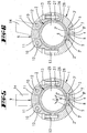
- the sealing surface 2 'of the tube 2 and the sealing surface 3' of the sealing strip 3 extends only over a achtel Vietnamese.
- the angle ⁇ over which the sealing surface extends may preferably be in a range of 30 to 60 °.
- the support of the tube 2 in the region of the slot 5 thus extends only over a limited peripheral region, which is formed by the curved surface 3 'of the socket-like inner wall 26 of the housing 1 superior sealing strip 3.
- an arcuate space 28 is formed between the outer wall 27 of the tube 2 and extending on an inner cylindrical surface inner wall 26 of the housing 1.
- the tube 2 forms a medium distributor and is mounted in the cavity of the half-tube.
- the tube 2 has a over the entire length of the tube 2 extending longitudinal slot 6.
- the longitudinal slot 6 is flanked by sealing surfaces 2 ', which rest in sealing contact with the counter-sealing surfaces 3' of the sealing strip 3.
- the sealing strip 3 extends with its running on an inner cylindrical surface counter-sealing surfaces 3 'only via Thus, only small radial forces are required in order to achieve a sufficiently high surface pressure in the region of the contact surfaces (sealing surfaces 2 ', 3').
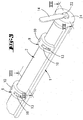
- the tube 2 is closed at its front ends with bearing plugs 16, 21.
- the bearing plugs 16, 21 may be glued to the tube 2.
- the bearing plug 21 forms a central projection 22 which is mounted with the interposition of a bearing ring in the bearing recess 24 'of the head piece 24.
- a portion of the bearing extension 22 is frontally over. Thereof a shift lever 14 is attached.
- the bearing plug 16 is mounted with the interposition of a bearing ring in the bearing recess 17 'of the head piece 17.
- the bearing plug 16 forms a central opening 19, in which a coupling piece 20 is screwed.
- the coupling piece 20 can be connected to a supply hose or supply pipe, so that through the feed opening 19, the interior 25 of the tube 2 can be filled with a flowable medium.
- the interior of the tube 2 thus forms a reservoir 25.
- each Anyak Gland 9 forms two each about a bearing axis 12 rotatable pressure rollers 10.
- the two ends of the An für Seae 9 are connected by means of clamping screws 13 with the two edges of the half tube. They complement the cross section of the half tube 1 to a full tube, wherein by means of the tensioning screws 13 can be applied and adjustable clamping force the pressure rollers 10 are brought into exciting contact with the outer wall of the tube 2.
- the a pressing piece 9 forming elbow has an inner wall facing the tube 2, which is spaced from the outer wall 27 of the tube 2.
- the pressure rollers 10 have portions that protrude into this space spacing.
- the pressure rollers 10 are offset laterally to a running through the radial slot 4 diametrical, so that the bearing axes 12 and the outlet nozzle form 4 points of an isosceles triangle.
- the pressing pieces 9 which are substantially uniformly spaced from one another in the axial direction, a force can be exerted on the tube 2 in the radial direction, which force is discharged into the superposed sealing surfaces 2 ', 3'.
- the clamping screws 13 the force can be adjusted locally, so that manufacturing tolerances in the course of the sealing surfaces 2 ', 3' can be compensated locally. If it comes to longer leaks to local leaks, they can be fixed by tightening the clamping screws 13 of the local An horraus 9.
- the operation of the device is the following:
- the reservoir 25 is fed with a flowable, in particular low to medium viscosity medium.
- this medium it is preferably a textured paint to be applied to a flat surface of a workpiece.
- the slot die is installed in a device, not shown, so that it can be displaced with respect to the workpiece or the workpiece relative to the slot die at a uniform speed.
- the medium can escape from the outlet nozzle 4. It enters first through the slot 6 in the only slightly interrupted, aligned flush slot 5 of the sealing strip 3 and from there into the likewise aligned longitudinal slot of the outlet nozzle 4.
- the opening of the outlet nozzle 4 is flanked by extending in the radial direction of lips 8, which are formed by mutually parallel cutouts.
- the application of the medium takes place either from top to bottom on horizontal surfaces or sideways in the vertical direction on vertical surfaces. But it is also possible to work with the slot die overhead, so that horizontal surfaces can be coated from below.
Landscapes
- Coating Apparatus (AREA)
Claims (14)
- Dispositif pour appliquer un matériau fluide sur une surface de pièce plane, comprenant un boîtier (1) ayant une buse de décharge du matériau (4) qui est allongée et un distributeur de matériau (2) agencé pivotant dans le boîtier (1) sous forme de tube cylindrique, lequel distributeur présente une fente (6) s'étendant suivant la direction axiale du tube, laquelle fente modifie sa position par rapport à la buse de décharge (4) par pivotement du distributeur de matériau (2), et dont la surface extérieure forme des surfaces d'étanchéité (2') qui sont en appuie étanche contre des contre-surfaces d'étanchéité (3'), dans lequel l'espace intérieur du tube (2) forme un réservoir (25) susceptible d'être alimenté avec le matériau par une ouverture d'alimentation (19), dans lequel la fente (6) s'étend de façon à ce qu'elle soit susceptible d'être déplacée par pivotement du distributeur de matériau (2), d'une position ouverte, dans laquelle elle forme une ouverture de passage du réservoir (25) à la buse de décharge (4) en étant ouverte sur sensiblement toute sa longueur, à une position fermée, dans laquelle l'ouverture de passage est complètement fermée, caractérisé en ce que les contre-surfaces d'étanchéité (3') sont formées par une barre d'étanchéité (3) logée dans un évidement (7) du boîtier (1) et laquelle présente une fente (5) alignée avec la buse de décharge (4).
- Dispositif selon la revendication 1, caractérisé en ce que le boîtier (1) forme un demi-tube présentant une fente axiale formant la buse de décharge (4).
- Dispositif selon l'une des revendications précédentes, caractérisé en ce que la barre d'étanchéité (3) fait saillie hors de l'évidement (7) à la manière d'un socle de façon à ce que la paroi intérieure (26) du boîtier (1) s'étende avec un espacement (28) par rapport à la paroi extérieure (27) du distributeur de matériau (2).
- Dispositif selon l'une des revendications précédentes, caractérisé en ce que la fente (5) de la barre d'étanchéité (3) est interrompue par des traverses (15) distantes les unes des autres.
- Dispositif selon l'une des revendications précédentes, caractérisé en ce que la buse de décharge (4) est flanquée de lèvres (8) s'étendant sensiblement en direction radiale.
- Dispositif pour appliquer un matériau fluide sur une surface de pièce plane, comprenant un boîtier (1) ayant une buse de décharge du matériau (4) qui est allongée et un distributeur de matériau (2) agencé pivotant dans le boîtier (1) sous forme de tube cylindrique, lequel distributeur présente une fente (6) s'étendant suivant la direction axiale du tube, laquelle fente modifie sa position par rapport à la buse de décharge (4) par pivotement du distributeur de matériau (2), et dont la surface extérieure forme des surfaces d'étanchéité (2') qui sont en appuie étanche contre des contre-surfaces d'étanchéité (3'), dans lequel l'espace intérieur du tube (2) forme un réservoir (25) susceptible d'être alimenté avec le matériau par une ouverture d'alimentation (19), dans lequel la fente (6) s'étend de façon à ce qu'elle soit susceptible d'être déplacée par pivotement du distributeur de matériau (2), d'une position ouverte, dans laquelle elle forme une ouverture de passage du réservoir (25) à la buse de décharge (4) en étant ouverte sur sensiblement toute sa longueur, à une position fermée, dans laquelle l'ouverture de passage est complètement fermée, selon l'une des revendications précédentes, caractérisé en ce que le distributeur de matériau (2) est pressé, avec un effort réglable localement, contre les contre-surfaces d'étanchéité (3') qui flanquent la fente (5) au moyen d'éléments presseurs (9) associés au boîtier (1) et distants les uns des autres suivant la direction axiale du tube (2).
- Dispositif selon la revendication 6, caractérisé en ce que les éléments presseurs (9) sont des pièces en forme d'étrier distantes les unes des autres, dans lequel les extrémités des étriers sont chacune bridées sur les bords du demi-tube (1).
- Dispositif selon l'une des revendications 6 ou 7, caractérisé en ce que les éléments presseurs (9) forment des rouleaux presseurs (10), lesquels sont disposés, dans une section transversale, à l'opposé de la buse de décharge (4) en formant un triangle isocèle et contre lesquels la paroi extérieure du distributeur de matériau (2) prend appui.
- Dispositif selon l'une des revendications précédentes, caractérisé en ce que les deux ouvertures frontales du tube (2) formant le distributeur de matériau sont obturées par des bouchons de montage (16, 21), dans lequel un bouchon de montage (21) présente une extension de montage (22) qui est monté dans une pièce de tête (24) du boîtier et l'autre bouchon de montage (16) forme l'ouverture d'alimentation (19) et est également monté dans une pièce de tête (17) du boîtier (1).
- Dispositif selon l'une des revendications précédentes, caractérisé en ce qu'une fente axiale formant la buse de décharge (4) s'étend sensiblement sur toute la longueur axiale du demi-tube (1) qui est pourvu de pièces de tête (17, 24) à ses deux extrémités.
- Dispositif selon la revendication 10, caractérisé en ce que la fente axiale (6) du tube (2) s'étend sensiblement sur toute la longueur axiale du tube (2) lequel est pourvu de bouchons de montage (16, 21) à chaque extrémité.
- Dispositif selon l'une des revendications précédentes, caractérisé en ce que la fente longitudinale (5) de la barre d'étanchéité (3), laquelle fente est alignée avec la buse de décharge (4), présente des interruptions formées par des traverses courtes (15) sensiblement équidistantes et qui est globalement plus courte que la fente longitudinale formant la buse de décharge (4) et la fente longitudinale (6) du distributeur de matériau (2).
- Dispositif selon la revendication 12, caractérisé en ce que la largeur des traverses (15) mesurée suivant la direction de la fente correspond approximativement à la largeur de la fente (5).
- Dispositif selon l'une des revendications 9 à 11, caractérisé par un levier de commande (14) agencé sur le bouchon de montage (21) pour faire pivoter le distributeur de matériau (2) entre la position ouverte et la position fermée.
Applications Claiming Priority (2)
| Application Number | Priority Date | Filing Date | Title |
|---|---|---|---|
| DE102008026147A DE102008026147A1 (de) | 2008-05-30 | 2008-05-30 | Breitschlitzdüse |
| PCT/EP2009/056589 WO2009144295A1 (fr) | 2008-05-30 | 2009-05-29 | Buse à large fente |
Publications (2)
| Publication Number | Publication Date |
|---|---|
| EP2282846A1 EP2282846A1 (fr) | 2011-02-16 |
| EP2282846B1 true EP2282846B1 (fr) | 2016-08-31 |
Family
ID=41020756
Family Applications (1)
| Application Number | Title | Priority Date | Filing Date |
|---|---|---|---|
| EP09753950.6A Not-in-force EP2282846B1 (fr) | 2008-05-30 | 2009-05-29 | Buse à large fente |
Country Status (5)
| Country | Link |
|---|---|
| US (1) | US8468967B2 (fr) |
| EP (1) | EP2282846B1 (fr) |
| DE (1) | DE102008026147A1 (fr) |
| ES (1) | ES2594435T3 (fr) |
| WO (1) | WO2009144295A1 (fr) |
Families Citing this family (4)
| Publication number | Priority date | Publication date | Assignee | Title |
|---|---|---|---|---|
| DE102014212940A1 (de) | 2014-07-03 | 2016-01-07 | Fraunhofer-Gesellschaft zur Förderung der angewandten Forschung e.V. | Modul, System und Verfahren zum Auftragen eines viskosen Mediums auf eine Oberfläche und Verfahren zum Herstellen des Moduls |
| USD815263S1 (en) * | 2015-07-14 | 2018-04-10 | Sussman Automatic Corporation | Steamhead for steam generator |
| SG11201810560XA (en) * | 2016-05-31 | 2018-12-28 | 3M Innovative Properties Co | Cam die coating systems |
| CN114833016B (zh) * | 2022-06-06 | 2023-03-24 | 广东越海集成技术有限公司 | 一种涂胶装置 |
Citations (2)
| Publication number | Priority date | Publication date | Assignee | Title |
|---|---|---|---|---|
| DE3322154A1 (de) * | 1982-08-21 | 1984-02-23 | Wolfgang Dipl.-Ing. 5000 Köln Breynk | Dosiervorrichtung |
| DE19757237C2 (de) * | 1997-12-22 | 2000-05-11 | Wolfgang Puffe | Rotationsauftragskopf |
Family Cites Families (8)
| Publication number | Priority date | Publication date | Assignee | Title |
|---|---|---|---|---|
| US3220653A (en) * | 1963-08-22 | 1965-11-30 | Amchem Prod | Liquid spraying device |
| GB1169973A (en) * | 1967-03-03 | 1969-11-12 | Berisfords Ltd | Apparatus for rendering Adhesives into Coherent Form |
| AT357505B (de) * | 1972-12-21 | 1980-07-10 | Zimmer Peter Ag | Mehrteilige spaltrakel fuer filmdruckmaschinen |
| JPH09327645A (ja) * | 1996-06-10 | 1997-12-22 | Kiroku Kobayashi | 高粘性塗料類の塗装用吐出ノズル装置 |
| DE10216356C1 (de) * | 2002-04-13 | 2003-09-18 | Wolfgang Puffe | Rotationskopf mit Abstreifleisten |
| DE10306884B3 (de) * | 2003-02-18 | 2004-06-03 | Wolfgang Puffe | Auftragskopf mit Drehschieberverschluss |
| DE102004034422B4 (de) * | 2004-07-15 | 2006-12-28 | Nordson Corp., Westlake | Auftragskopf mit im Gehäuse federnd abgestütztem Düsenblock |
| DE202006016674U1 (de) * | 2006-10-27 | 2007-02-22 | Nordson Corporation, Westlake | Auftragsvorrichtung zum Auftragen von flüssigem Material |
-
2008
- 2008-05-30 DE DE102008026147A patent/DE102008026147A1/de not_active Ceased
-
2009
- 2009-05-29 EP EP09753950.6A patent/EP2282846B1/fr not_active Not-in-force
- 2009-05-29 WO PCT/EP2009/056589 patent/WO2009144295A1/fr not_active Ceased
- 2009-05-29 ES ES09753950.6T patent/ES2594435T3/es active Active
-
2010
- 2010-11-30 US US12/956,790 patent/US8468967B2/en not_active Expired - Fee Related
Patent Citations (2)
| Publication number | Priority date | Publication date | Assignee | Title |
|---|---|---|---|---|
| DE3322154A1 (de) * | 1982-08-21 | 1984-02-23 | Wolfgang Dipl.-Ing. 5000 Köln Breynk | Dosiervorrichtung |
| DE19757237C2 (de) * | 1997-12-22 | 2000-05-11 | Wolfgang Puffe | Rotationsauftragskopf |
Also Published As
| Publication number | Publication date |
|---|---|
| US8468967B2 (en) | 2013-06-25 |
| ES2594435T3 (es) | 2016-12-20 |
| DE102008026147A1 (de) | 2009-12-03 |
| WO2009144295A1 (fr) | 2009-12-03 |
| EP2282846A1 (fr) | 2011-02-16 |
| US20110132940A1 (en) | 2011-06-09 |
Similar Documents
| Publication | Publication Date | Title |
|---|---|---|
| EP1632293B1 (fr) | Buse de distribution d'une substance fluide | |
| DE3630961C2 (fr) | ||
| WO2011003493A1 (fr) | Pistolet pulvérisateur à peinture | |
| EP2145695A1 (fr) | Dispositif d'application d'adhésif | |
| EP1352691B1 (fr) | Tête d'application rotative | |
| EP1358945A2 (fr) | Dispositif pour appliquer un matériau fluide sur un substrat, en particulier pour l'application intermittante d'adhésif liquide | |
| WO2000067914A2 (fr) | Dispositif pour l'application de fluide | |
| EP2377623B1 (fr) | Dispositif d'application d'une matière liquide sur un substrat | |
| EP2282846A1 (fr) | Buse à large fente | |
| DE19602483C1 (de) | Rollrakelbaugruppe | |
| DE202006014743U1 (de) | Vorrichtung zum Auftragen von Fluiden wie Klebstoff, insbesondere Schmelzkleber | |
| WO2000030768A1 (fr) | Rouleau pour appliquer une substance a etaler, notamment rouleau a peinture | |
| DE4017558C2 (de) | Verwendung von Drehkörpern zur Variation des Durchschnittsquerschnitts für das Kunststoffmaterial in Planetwalzen-Extrudern | |
| DE9102635U1 (de) | Mundstück-Absperrvorrichtung für Ein- oder Mehrkomponentenkartuschen für plastische Massen | |
| DE2532855A1 (de) | Vorrichtung zum beschichten von leisten | |
| EP0477769A2 (fr) | Dispositif de collage transversal pour l'application de colle sur une bande en mouvement | |
| DE10253410A1 (de) | Verbesserungen an den Köpfen zum Auftragen von Schmelzklebstoffen | |
| DE202006019724U1 (de) | Vorrichtung mit Schlitzdüsenanordnung zum Abgeben von Fluid | |
| DE10306884B3 (de) | Auftragskopf mit Drehschieberverschluss | |
| DE3919546C2 (fr) | ||
| DE3234963A1 (de) | Giesskopf | |
| DE202009001870U1 (de) | Handbetätigte Vorrichtung zum Verteilen einer Auftragsmasse auf einer Tragfläche | |
| DE3115818C2 (fr) | ||
| DE2737993A1 (de) | Vorrichtung zum ausgeben von klebstoff | |
| EP1240949A2 (fr) | Dispositif de distribution de fluides, en particulier d'adhésifs fluides |
Legal Events
| Date | Code | Title | Description |
|---|---|---|---|
| PUAI | Public reference made under article 153(3) epc to a published international application that has entered the european phase |
Free format text: ORIGINAL CODE: 0009012 |
|
| 17P | Request for examination filed |
Effective date: 20101203 |
|
| AK | Designated contracting states |
Kind code of ref document: A1 Designated state(s): AT BE BG CH CY CZ DE DK EE ES FI FR GB GR HR HU IE IS IT LI LT LU LV MC MK MT NL NO PL PT RO SE SI SK TR |
|
| AX | Request for extension of the european patent |
Extension state: AL BA RS |
|
| DAX | Request for extension of the european patent (deleted) | ||
| 17Q | First examination report despatched |
Effective date: 20160112 |
|
| GRAP | Despatch of communication of intention to grant a patent |
Free format text: ORIGINAL CODE: EPIDOSNIGR1 |
|
| INTG | Intention to grant announced |
Effective date: 20160331 |
|
| GRAJ | Information related to disapproval of communication of intention to grant by the applicant or resumption of examination proceedings by the epo deleted |
Free format text: ORIGINAL CODE: EPIDOSDIGR1 |
|
| GRAS | Grant fee paid |
Free format text: ORIGINAL CODE: EPIDOSNIGR3 |
|
| GRAP | Despatch of communication of intention to grant a patent |
Free format text: ORIGINAL CODE: EPIDOSNIGR1 |
|
| GRAA | (expected) grant |
Free format text: ORIGINAL CODE: 0009210 |
|
| INTC | Intention to grant announced (deleted) | ||
| INTG | Intention to grant announced |
Effective date: 20160726 |
|
| AK | Designated contracting states |
Kind code of ref document: B1 Designated state(s): AT BE BG CH CY CZ DE DK EE ES FI FR GB GR HR HU IE IS IT LI LT LU LV MC MK MT NL NO PL PT RO SE SI SK TR |
|
| REG | Reference to a national code |
Ref country code: CH Ref legal event code: EP Ref country code: GB Ref legal event code: FG4D Free format text: NOT ENGLISH |
|
| REG | Reference to a national code |
Ref country code: IE Ref legal event code: FG4D Free format text: LANGUAGE OF EP DOCUMENT: GERMAN |
|
| REG | Reference to a national code |
Ref country code: DE Ref legal event code: R096 Ref document number: 502009013029 Country of ref document: DE |
|
| REG | Reference to a national code |
Ref country code: AT Ref legal event code: REF Ref document number: 824535 Country of ref document: AT Kind code of ref document: T Effective date: 20161015 |
|
| REG | Reference to a national code |
Ref country code: ES Ref legal event code: FG2A Ref document number: 2594435 Country of ref document: ES Kind code of ref document: T3 Effective date: 20161220 |
|
| REG | Reference to a national code |
Ref country code: LT Ref legal event code: MG4D |
|
| REG | Reference to a national code |
Ref country code: NL Ref legal event code: MP Effective date: 20160831 |
|
| PG25 | Lapsed in a contracting state [announced via postgrant information from national office to epo] |
Ref country code: LT Free format text: LAPSE BECAUSE OF FAILURE TO SUBMIT A TRANSLATION OF THE DESCRIPTION OR TO PAY THE FEE WITHIN THE PRESCRIBED TIME-LIMIT Effective date: 20160831 Ref country code: FI Free format text: LAPSE BECAUSE OF FAILURE TO SUBMIT A TRANSLATION OF THE DESCRIPTION OR TO PAY THE FEE WITHIN THE PRESCRIBED TIME-LIMIT Effective date: 20160831 Ref country code: HR Free format text: LAPSE BECAUSE OF FAILURE TO SUBMIT A TRANSLATION OF THE DESCRIPTION OR TO PAY THE FEE WITHIN THE PRESCRIBED TIME-LIMIT Effective date: 20160831 Ref country code: NO Free format text: LAPSE BECAUSE OF FAILURE TO SUBMIT A TRANSLATION OF THE DESCRIPTION OR TO PAY THE FEE WITHIN THE PRESCRIBED TIME-LIMIT Effective date: 20161130 |
|
| PG25 | Lapsed in a contracting state [announced via postgrant information from national office to epo] |
Ref country code: NL Free format text: LAPSE BECAUSE OF FAILURE TO SUBMIT A TRANSLATION OF THE DESCRIPTION OR TO PAY THE FEE WITHIN THE PRESCRIBED TIME-LIMIT Effective date: 20160831 Ref country code: GR Free format text: LAPSE BECAUSE OF FAILURE TO SUBMIT A TRANSLATION OF THE DESCRIPTION OR TO PAY THE FEE WITHIN THE PRESCRIBED TIME-LIMIT Effective date: 20161201 Ref country code: LV Free format text: LAPSE BECAUSE OF FAILURE TO SUBMIT A TRANSLATION OF THE DESCRIPTION OR TO PAY THE FEE WITHIN THE PRESCRIBED TIME-LIMIT Effective date: 20160831 Ref country code: SE Free format text: LAPSE BECAUSE OF FAILURE TO SUBMIT A TRANSLATION OF THE DESCRIPTION OR TO PAY THE FEE WITHIN THE PRESCRIBED TIME-LIMIT Effective date: 20160831 |
|
| PG25 | Lapsed in a contracting state [announced via postgrant information from national office to epo] |
Ref country code: RO Free format text: LAPSE BECAUSE OF FAILURE TO SUBMIT A TRANSLATION OF THE DESCRIPTION OR TO PAY THE FEE WITHIN THE PRESCRIBED TIME-LIMIT Effective date: 20160831 Ref country code: EE Free format text: LAPSE BECAUSE OF FAILURE TO SUBMIT A TRANSLATION OF THE DESCRIPTION OR TO PAY THE FEE WITHIN THE PRESCRIBED TIME-LIMIT Effective date: 20160831 |
|
| REG | Reference to a national code |
Ref country code: FR Ref legal event code: PLFP Year of fee payment: 9 |
|
| PG25 | Lapsed in a contracting state [announced via postgrant information from national office to epo] |
Ref country code: DK Free format text: LAPSE BECAUSE OF FAILURE TO SUBMIT A TRANSLATION OF THE DESCRIPTION OR TO PAY THE FEE WITHIN THE PRESCRIBED TIME-LIMIT Effective date: 20160831 Ref country code: BG Free format text: LAPSE BECAUSE OF FAILURE TO SUBMIT A TRANSLATION OF THE DESCRIPTION OR TO PAY THE FEE WITHIN THE PRESCRIBED TIME-LIMIT Effective date: 20161130 Ref country code: PT Free format text: LAPSE BECAUSE OF FAILURE TO SUBMIT A TRANSLATION OF THE DESCRIPTION OR TO PAY THE FEE WITHIN THE PRESCRIBED TIME-LIMIT Effective date: 20170102 Ref country code: CZ Free format text: LAPSE BECAUSE OF FAILURE TO SUBMIT A TRANSLATION OF THE DESCRIPTION OR TO PAY THE FEE WITHIN THE PRESCRIBED TIME-LIMIT Effective date: 20160831 Ref country code: SK Free format text: LAPSE BECAUSE OF FAILURE TO SUBMIT A TRANSLATION OF THE DESCRIPTION OR TO PAY THE FEE WITHIN THE PRESCRIBED TIME-LIMIT Effective date: 20160831 Ref country code: PL Free format text: LAPSE BECAUSE OF FAILURE TO SUBMIT A TRANSLATION OF THE DESCRIPTION OR TO PAY THE FEE WITHIN THE PRESCRIBED TIME-LIMIT Effective date: 20160831 |
|
| REG | Reference to a national code |
Ref country code: DE Ref legal event code: R097 Ref document number: 502009013029 Country of ref document: DE |
|
| PG25 | Lapsed in a contracting state [announced via postgrant information from national office to epo] |
Ref country code: IT Free format text: LAPSE BECAUSE OF FAILURE TO SUBMIT A TRANSLATION OF THE DESCRIPTION OR TO PAY THE FEE WITHIN THE PRESCRIBED TIME-LIMIT Effective date: 20160831 |
|
| PLBE | No opposition filed within time limit |
Free format text: ORIGINAL CODE: 0009261 |
|
| STAA | Information on the status of an ep patent application or granted ep patent |
Free format text: STATUS: NO OPPOSITION FILED WITHIN TIME LIMIT |
|
| 26N | No opposition filed |
Effective date: 20170601 |
|
| PG25 | Lapsed in a contracting state [announced via postgrant information from national office to epo] |
Ref country code: SI Free format text: LAPSE BECAUSE OF FAILURE TO SUBMIT A TRANSLATION OF THE DESCRIPTION OR TO PAY THE FEE WITHIN THE PRESCRIBED TIME-LIMIT Effective date: 20160831 Ref country code: LU Free format text: LAPSE BECAUSE OF NON-PAYMENT OF DUE FEES Effective date: 20170531 |
|
| REG | Reference to a national code |
Ref country code: CH Ref legal event code: PL |
|
| PG25 | Lapsed in a contracting state [announced via postgrant information from national office to epo] |
Ref country code: MC Free format text: LAPSE BECAUSE OF FAILURE TO SUBMIT A TRANSLATION OF THE DESCRIPTION OR TO PAY THE FEE WITHIN THE PRESCRIBED TIME-LIMIT Effective date: 20160831 |
|
| REG | Reference to a national code |
Ref country code: IE Ref legal event code: MM4A |
|
| PG25 | Lapsed in a contracting state [announced via postgrant information from national office to epo] |
Ref country code: LI Free format text: LAPSE BECAUSE OF NON-PAYMENT OF DUE FEES Effective date: 20170531 Ref country code: CH Free format text: LAPSE BECAUSE OF NON-PAYMENT OF DUE FEES Effective date: 20170531 |
|
| PG25 | Lapsed in a contracting state [announced via postgrant information from national office to epo] |
Ref country code: LU Free format text: LAPSE BECAUSE OF NON-PAYMENT OF DUE FEES Effective date: 20170529 |
|
| REG | Reference to a national code |
Ref country code: BE Ref legal event code: MM Effective date: 20170531 |
|
| PG25 | Lapsed in a contracting state [announced via postgrant information from national office to epo] |
Ref country code: IE Free format text: LAPSE BECAUSE OF NON-PAYMENT OF DUE FEES Effective date: 20170529 |
|
| REG | Reference to a national code |
Ref country code: FR Ref legal event code: PLFP Year of fee payment: 10 |
|
| REG | Reference to a national code |
Ref country code: AT Ref legal event code: MM01 Ref document number: 824535 Country of ref document: AT Kind code of ref document: T Effective date: 20170529 |
|
| PG25 | Lapsed in a contracting state [announced via postgrant information from national office to epo] |
Ref country code: AT Free format text: LAPSE BECAUSE OF NON-PAYMENT OF DUE FEES Effective date: 20170529 Ref country code: BE Free format text: LAPSE BECAUSE OF NON-PAYMENT OF DUE FEES Effective date: 20170531 |
|
| PG25 | Lapsed in a contracting state [announced via postgrant information from national office to epo] |
Ref country code: MT Free format text: LAPSE BECAUSE OF FAILURE TO SUBMIT A TRANSLATION OF THE DESCRIPTION OR TO PAY THE FEE WITHIN THE PRESCRIBED TIME-LIMIT Effective date: 20160831 |
|
| PG25 | Lapsed in a contracting state [announced via postgrant information from national office to epo] |
Ref country code: HU Free format text: LAPSE BECAUSE OF FAILURE TO SUBMIT A TRANSLATION OF THE DESCRIPTION OR TO PAY THE FEE WITHIN THE PRESCRIBED TIME-LIMIT; INVALID AB INITIO Effective date: 20090529 |
|
| PG25 | Lapsed in a contracting state [announced via postgrant information from national office to epo] |
Ref country code: CY Free format text: LAPSE BECAUSE OF NON-PAYMENT OF DUE FEES Effective date: 20160831 |
|
| PG25 | Lapsed in a contracting state [announced via postgrant information from national office to epo] |
Ref country code: MK Free format text: LAPSE BECAUSE OF FAILURE TO SUBMIT A TRANSLATION OF THE DESCRIPTION OR TO PAY THE FEE WITHIN THE PRESCRIBED TIME-LIMIT Effective date: 20160831 |
|
| PG25 | Lapsed in a contracting state [announced via postgrant information from national office to epo] |
Ref country code: TR Free format text: LAPSE BECAUSE OF FAILURE TO SUBMIT A TRANSLATION OF THE DESCRIPTION OR TO PAY THE FEE WITHIN THE PRESCRIBED TIME-LIMIT Effective date: 20160831 |
|
| PG25 | Lapsed in a contracting state [announced via postgrant information from national office to epo] |
Ref country code: IS Free format text: LAPSE BECAUSE OF FAILURE TO SUBMIT A TRANSLATION OF THE DESCRIPTION OR TO PAY THE FEE WITHIN THE PRESCRIBED TIME-LIMIT Effective date: 20161231 |
|
| P01 | Opt-out of the competence of the unified patent court (upc) registered |
Effective date: 20230524 |
|
| PGFP | Annual fee paid to national office [announced via postgrant information from national office to epo] |
Ref country code: ES Payment date: 20230621 Year of fee payment: 15 |
|
| PGFP | Annual fee paid to national office [announced via postgrant information from national office to epo] |
Ref country code: GB Payment date: 20240522 Year of fee payment: 16 |
|
| PGFP | Annual fee paid to national office [announced via postgrant information from national office to epo] |
Ref country code: DE Payment date: 20240517 Year of fee payment: 16 |
|
| PGFP | Annual fee paid to national office [announced via postgrant information from national office to epo] |
Ref country code: FR Payment date: 20240522 Year of fee payment: 16 |
|
| REG | Reference to a national code |
Ref country code: ES Ref legal event code: FD2A Effective date: 20250703 |
|
| PG25 | Lapsed in a contracting state [announced via postgrant information from national office to epo] |
Ref country code: ES Free format text: LAPSE BECAUSE OF NON-PAYMENT OF DUE FEES Effective date: 20240530 |
|
| REG | Reference to a national code |
Ref country code: DE Ref legal event code: R119 Ref document number: 502009013029 Country of ref document: DE |
|
| GBPC | Gb: european patent ceased through non-payment of renewal fee |
Effective date: 20250529 |
|
| PG25 | Lapsed in a contracting state [announced via postgrant information from national office to epo] |
Ref country code: GB Free format text: LAPSE BECAUSE OF NON-PAYMENT OF DUE FEES Effective date: 20250529 |
|
| PG25 | Lapsed in a contracting state [announced via postgrant information from national office to epo] |
Ref country code: DE Free format text: LAPSE BECAUSE OF NON-PAYMENT OF DUE FEES Effective date: 20251202 |
|
| PG25 | Lapsed in a contracting state [announced via postgrant information from national office to epo] |
Ref country code: FR Free format text: LAPSE BECAUSE OF NON-PAYMENT OF DUE FEES Effective date: 20250531 |