EP3200967B1 - Extrusionsblasformverfahren und zugehöriger roboter - Google Patents
Extrusionsblasformverfahren und zugehöriger roboter Download PDFInfo
- Publication number
- EP3200967B1 EP3200967B1 EP15763890.9A EP15763890A EP3200967B1 EP 3200967 B1 EP3200967 B1 EP 3200967B1 EP 15763890 A EP15763890 A EP 15763890A EP 3200967 B1 EP3200967 B1 EP 3200967B1
- Authority
- EP
- European Patent Office
- Prior art keywords
- blow
- mould
- clamp
- extrusion
- parison
- Prior art date
- Legal status (The legal status is an assumption and is not a legal conclusion. Google has not performed a legal analysis and makes no representation as to the accuracy of the status listed.)
- Active
Links
- 238000010101 extrusion blow moulding Methods 0.000 title claims description 10
- 238000001125 extrusion Methods 0.000 claims description 72
- 238000003780 insertion Methods 0.000 claims description 50
- 230000037431 insertion Effects 0.000 claims description 50
- 238000000034 method Methods 0.000 claims description 19
- 238000000071 blow moulding Methods 0.000 claims description 18
- 238000007664 blowing Methods 0.000 description 49
- 238000009434 installation Methods 0.000 description 27
- 230000000717 retained effect Effects 0.000 description 6
- 238000004519 manufacturing process Methods 0.000 description 4
- 238000007373 indentation Methods 0.000 description 3
- 239000012815 thermoplastic material Substances 0.000 description 3
- 230000005484 gravity Effects 0.000 description 2
- 238000001816 cooling Methods 0.000 description 1
- 238000010586 diagram Methods 0.000 description 1
- 239000008187 granular material Substances 0.000 description 1
- 239000013529 heat transfer fluid Substances 0.000 description 1
- 238000011065 in-situ storage Methods 0.000 description 1
- 239000000463 material Substances 0.000 description 1
- 238000002844 melting Methods 0.000 description 1
- 230000008018 melting Effects 0.000 description 1
- 239000012768 molten material Substances 0.000 description 1
- 238000004064 recycling Methods 0.000 description 1
- 229920001169 thermoplastic Polymers 0.000 description 1
- 239000004416 thermosoftening plastic Substances 0.000 description 1
Images


Classifications
-
- B—PERFORMING OPERATIONS; TRANSPORTING
- B29—WORKING OF PLASTICS; WORKING OF SUBSTANCES IN A PLASTIC STATE IN GENERAL
- B29C—SHAPING OR JOINING OF PLASTICS; SHAPING OF MATERIAL IN A PLASTIC STATE, NOT OTHERWISE PROVIDED FOR; AFTER-TREATMENT OF THE SHAPED PRODUCTS, e.g. REPAIRING
- B29C49/00—Blow-moulding, i.e. blowing a preform or parison to a desired shape within a mould; Apparatus therefor
- B29C49/28—Blow-moulding apparatus
- B29C49/30—Blow-moulding apparatus having movable moulds or mould parts
- B29C49/32—Blow-moulding apparatus having movable moulds or mould parts moving "to and fro"
-
- B—PERFORMING OPERATIONS; TRANSPORTING
- B29—WORKING OF PLASTICS; WORKING OF SUBSTANCES IN A PLASTIC STATE IN GENERAL
- B29C—SHAPING OR JOINING OF PLASTICS; SHAPING OF MATERIAL IN A PLASTIC STATE, NOT OTHERWISE PROVIDED FOR; AFTER-TREATMENT OF THE SHAPED PRODUCTS, e.g. REPAIRING
- B29C49/00—Blow-moulding, i.e. blowing a preform or parison to a desired shape within a mould; Apparatus therefor
- B29C49/02—Combined blow-moulding and manufacture of the preform or the parison
- B29C49/04—Extrusion blow-moulding
- B29C49/0411—Means for defining the wall or layer thickness
-
- B—PERFORMING OPERATIONS; TRANSPORTING
- B29—WORKING OF PLASTICS; WORKING OF SUBSTANCES IN A PLASTIC STATE IN GENERAL
- B29C—SHAPING OR JOINING OF PLASTICS; SHAPING OF MATERIAL IN A PLASTIC STATE, NOT OTHERWISE PROVIDED FOR; AFTER-TREATMENT OF THE SHAPED PRODUCTS, e.g. REPAIRING
- B29C49/00—Blow-moulding, i.e. blowing a preform or parison to a desired shape within a mould; Apparatus therefor
- B29C49/24—Lining or labelling
-
- B—PERFORMING OPERATIONS; TRANSPORTING
- B29—WORKING OF PLASTICS; WORKING OF SUBSTANCES IN A PLASTIC STATE IN GENERAL
- B29C—SHAPING OR JOINING OF PLASTICS; SHAPING OF MATERIAL IN A PLASTIC STATE, NOT OTHERWISE PROVIDED FOR; AFTER-TREATMENT OF THE SHAPED PRODUCTS, e.g. REPAIRING
- B29C49/00—Blow-moulding, i.e. blowing a preform or parison to a desired shape within a mould; Apparatus therefor
- B29C49/42—Component parts, details or accessories; Auxiliary operations
- B29C49/4205—Handling means, e.g. transfer, loading or discharging means
- B29C49/42069—Means explicitly adapted for transporting blown article
-
- B—PERFORMING OPERATIONS; TRANSPORTING
- B29—WORKING OF PLASTICS; WORKING OF SUBSTANCES IN A PLASTIC STATE IN GENERAL
- B29C—SHAPING OR JOINING OF PLASTICS; SHAPING OF MATERIAL IN A PLASTIC STATE, NOT OTHERWISE PROVIDED FOR; AFTER-TREATMENT OF THE SHAPED PRODUCTS, e.g. REPAIRING
- B29C49/00—Blow-moulding, i.e. blowing a preform or parison to a desired shape within a mould; Apparatus therefor
- B29C49/24—Lining or labelling
- B29C2049/2412—Lining or labelling outside the article
-
- B—PERFORMING OPERATIONS; TRANSPORTING
- B29—WORKING OF PLASTICS; WORKING OF SUBSTANCES IN A PLASTIC STATE IN GENERAL
- B29C—SHAPING OR JOINING OF PLASTICS; SHAPING OF MATERIAL IN A PLASTIC STATE, NOT OTHERWISE PROVIDED FOR; AFTER-TREATMENT OF THE SHAPED PRODUCTS, e.g. REPAIRING
- B29C49/00—Blow-moulding, i.e. blowing a preform or parison to a desired shape within a mould; Apparatus therefor
- B29C49/24—Lining or labelling
- B29C2049/2443—Means for feeding the lining or label into the mould, preform or parison, e.g. grippers
-
- B—PERFORMING OPERATIONS; TRANSPORTING
- B29—WORKING OF PLASTICS; WORKING OF SUBSTANCES IN A PLASTIC STATE IN GENERAL
- B29C—SHAPING OR JOINING OF PLASTICS; SHAPING OF MATERIAL IN A PLASTIC STATE, NOT OTHERWISE PROVIDED FOR; AFTER-TREATMENT OF THE SHAPED PRODUCTS, e.g. REPAIRING
- B29C49/00—Blow-moulding, i.e. blowing a preform or parison to a desired shape within a mould; Apparatus therefor
- B29C49/24—Lining or labelling
- B29C2049/2479—Label or lining movements
- B29C2049/2483—Label or lining movements horizontal only
-
- B—PERFORMING OPERATIONS; TRANSPORTING
- B29—WORKING OF PLASTICS; WORKING OF SUBSTANCES IN A PLASTIC STATE IN GENERAL
- B29K—INDEXING SCHEME ASSOCIATED WITH SUBCLASSES B29B, B29C OR B29D, RELATING TO MOULDING MATERIALS OR TO MATERIALS FOR MOULDS, REINFORCEMENTS, FILLERS OR PREFORMED PARTS, e.g. INSERTS
- B29K2101/00—Use of unspecified macromolecular compounds as moulding material
- B29K2101/12—Thermoplastic materials
-
- B—PERFORMING OPERATIONS; TRANSPORTING
- B29—WORKING OF PLASTICS; WORKING OF SUBSTANCES IN A PLASTIC STATE IN GENERAL
- B29K—INDEXING SCHEME ASSOCIATED WITH SUBCLASSES B29B, B29C OR B29D, RELATING TO MOULDING MATERIALS OR TO MATERIALS FOR MOULDS, REINFORCEMENTS, FILLERS OR PREFORMED PARTS, e.g. INSERTS
- B29K2105/00—Condition, form or state of moulded material or of the material to be shaped
- B29K2105/25—Solid
- B29K2105/253—Preform
- B29K2105/258—Tubular
-
- B—PERFORMING OPERATIONS; TRANSPORTING
- B29—WORKING OF PLASTICS; WORKING OF SUBSTANCES IN A PLASTIC STATE IN GENERAL
- B29L—INDEXING SCHEME ASSOCIATED WITH SUBCLASS B29C, RELATING TO PARTICULAR ARTICLES
- B29L2031/00—Other particular articles
- B29L2031/712—Containers; Packaging elements or accessories, Packages
Definitions
- the present invention provides an extrusion blow molding process for the manufacture of blown articles incorporating at least one integrated in-situ label. It also relates to a robot implementing said method.
- the documents US2007 / 176330A1 , US6499988B1 and DE20000188U1 are representative of the prior art in the technical field of demand.
- the extrusion blow molding process has been known for a long time for the manufacture of hollow objects such as containers, bottles, jars or bottles of thermoplastic material.
- the method is based on the extrusion by an extrusion head of a parison 3 having a tubular shape which is then cut, placed in a mold and blown to take the shape of mold cavity.
- a conventional extrusion blow molding machine comprises an extruder which prepares material initially in the form of granules of thermoplastic paste under pressure and an extrusion head 1 which transfers the molten material from the extruder to a die that regulates the shape and thickness of the parison 3.
- a robot is arranged next to the extruder to maneuver a mold 311 and evacuate the blown objects. Cooling channels in which circulates a heat transfer fluid are used to evacuate the heat of the thermoplastic material to solidify the piece in the mold 311.
- the robot comprises a clamp 31 comprising the mold 311 for closing the mold around the parison 3 extruded by the extrusion head 1 in an extrusion direction, generally vertical.
- the mold 311 has two shells 3111 with the cavities 3112, the shells being movable in a nip direction perpendicular to the extrusion direction.
- the clamp 31 further comprises gripping means 312 for taking back a first blown object 36a retained by a blowing rod 33.
- Transfer means for transferring the clamp 31 in a transfer direction perpendicular to the extrusion direction and to the pinch direction.
- the blowing rod 33 is slidably mounted in the extrusion direction, offset from the pitch produced by the transfer means, to fit on one end of the parison 3 to blow it into the mold 311 and form a second blown object 36b .
- An exhaust system 35 is disposed in the transfer direction to receive the first blown object 36a.
- the blowing rod 33 is also able to retain the second object 36b during the opening of the mold 311.
- insertion means 34 are disposed opposite the clamp 31 with respect to the extrusion axis to insert at least one sheet on the surface of at least one of the indentations.
- the sheet is pressed between the wall of the mold and the wall of the blown object and then integrates by at least partial melting to the wall of the blown object.
- This makes it possible to cover the outer surface of the blown article with, for example, a label.
- the sheet is preferably in a thermoplastic material to facilitate recycling of the blown object.
- the label is strongly related to the wall of the blown object, which gives it a high quality of outfit.
- Blown objects are manufactured by such an installation by a succession of cycles of which only one is described below, the others being identical.
- the first stage of the cycle is chosen arbitrarily.
- the following description refers to first and second blown objects 36a, 36b which are consecutive objects in the manufacturing cycle.
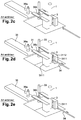
- parison 3 In an initial position, represented on the figure 2a , parison 3 is being extruded.
- the mold 311 is closed and the clamp 31 is disengaged from the extrusion head 1.
- the blowing rod 33 is engaged in the mold 31 which contains the second blown object 36b.
- the gripping means 312 hold by a neck the first blown object 36a above the evacuation system.
- the clamp 31 opens so that the second object 36b is released from the mold 311.
- the gripping means 312 release the first object which is thus transferred to the discharge system 35, for example a conveyor belt.
- the transfer means move the clamp 31 to place the mold 311 around the parison 3.
- the insertion means 34 in the form of sliding arms, introduce two sheets to place respectively in the footprints of the two shells of the mold 311, and deposited.
- the clamp 31 closes so as to insert the parison 3 in the mold.
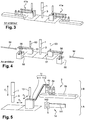
- the portion of the parison 3 in the mold is cut away from the parison 3 during extrusion.
- the gripping means 312 grip the second object 36b blown by the neck, near the connection with the blow pipe 33.
- the blowing rod 33 moves upwards to disengage from the second object 36b blown, held by the gripping means 312.
- the transfer means move the clamp 31 with the second object 36b so that the blow rod 33 is facing the mold 311. At this moment, the second blown object 36b is above the exhaust system 35.
- the blast rod 33 descends and blows air into the parison 3 to press the walls of the parison 3 into the footprints of shells.
- a third object is thus formed, bearing on its surface the sheets which have been inserted in the mold 311.
- the position reached is that of the initial position, except that the second object 36b has replaced the first in the gripping means 312.
- the cycle then resumes in the first step.
- the installation then comprises a robot formed of two robots as described above placed on either side of the extruder, except the insertion means.
- the second clamp 41b takes the place of the insertion means of the first set and vice versa. In this configuration, it is not possible to have the insertion of sheets into the molds.
- the gobs 3 produced are taken alternately by one or other of the clamps 41a, 41b.
- the invention aims to provide a method and an extrusion blowing robot limiting the size, maintaining a good rigidity of the insertion means and allowing the use of an evacuation system.
- the placement of the sheet in the mold is performed not when the mold is around the parison, but before the transfer of the mold in this place while the second blown object is extracted to the second level.
- the space between the shells of the mold is then completely free. It is thus possible to use insertion means that are less constrained by the free space, which makes it possible to gain in placement precision of the sheet or sheets in the mold without increasing the opening stroke of the mold.
- the evacuation system placed at the second level is above the insertion means, which limits the footprint of the installation.
- the extrusion head can make a parison or more, in which case the mold has as many cavities as gobs to form as many objects.
- the blowing rod is also duplicated or subdivided in order to blow in each parison and to take up as many objects.
- This process uses two blowing stations. It allows the installation with a small footprint since the two evacuation systems are superimposed on the insertion means.
- the insertion of the sheets is carried out without the presence or the parison neither that of the blown object.
- the insertion means can be in the immediate vicinity of the mold, which reduces the length of the sliding arms for the insertion means.
- an extrusion blow molding installation comprises an extruder of which only a head 1 is shown in the figures and a robot 2 according to a first embodiment of the invention.
- the extrusion head 1 continuously produces a parison 3 of tubular shape in an extrusion direction F1, in this case vertically and downwards.
- the robot 2 comprises a first clamp 11 comprising a first mold 111 for closing the first mold 111 around the parison 3.
- the first mold 111 comprises shells 1111 with cavities 1112.
- the shells 1111 are movable in a first pinch direction F2 perpendicular to the extrusion direction F1, that is to say horizontally.
- the robot 2 further comprises first transfer means, not shown, for transferring the first clamp 11 in a first transfer direction F3 between the extrusion head 1 and a first blowing station along a first level A.
- the first transfer direction F3 may for example be oblique with respect to the extrusion direction F1 and perpendicular to the first gripping direction F2. In this case, the first transfer direction F3 is perpendicular to the extrusion direction F1, and therefore horizontal.
- the first clamp 11 further comprises first gripping means 112 to take a first blown object 4a and transfer it, in a detailed manner below.
- the robot 2 comprises at the blowing station a first blowing rod 13 slidably mounted in the extrusion direction F1.
- the first blowing rod 13 is adapted to be inserted, in a blowing position, on one end of the parison 3 at the first blowing station to blow it into the first mold 111 and form a second blown object 4b.
- the first blow pipe 13 is further adapted to hold the second blown object 4b to take it to a second level B greater than the first level A so as to leave the second blown object 4b of the first mold 111.
- the robot 2 further comprises first insertion means 14 for inserting a sheet 5 on the surface of each of the cavities 1112 when the first mold 111 is at the blowing station, in the open position.
- the first insertion means 14 comprises two arms 141 slidably mounted, each arm 141 ending in a gripping device 142 adapted to support and transport one of the sheets 5 to present it facing the corresponding shell 1111.
- the arm 141 or the gripping device 142 is further able to move in the niping direction to deposit and transfer the sheet 5 to the shell 1111 in the cavity 1112, in a manner known per se. In the case of the removal of the leaf only in one of the shells, one can use only one arm.
- the robot 2 also comprises a first evacuation system 15 arranged to receive the first blown object 4a by the first gripping means 112 during the opening of the first clamp 11.
- the robot 2 is driven, for example by a not shown programmable controller, to implement the method that will be described now.
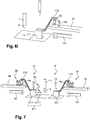
- parison 3 In an initial position, represented on the figure 6a , parison 3 is being extruded.
- the first mold 111 is closed and the first clamp 11 is at the blowing station.
- the first blowpipe 13 is engaged in the first mold 111 which contains the second blown object 4b.
- the first gripping means 112 hold by a neck the first blown object 4a above the first discharge system 15.
- the first clamp 11 opens so that the second blown object 4b is released from the first mold 111 being held at the end of the second blowing rod.
- the first gripping means 112 release the first blown object 4a which is thus transferred to the first discharge system 15.
- the first blowpipe 13 transfers the second object of the first level A to the second level B.
- the first insertion means 14 introduce two sheets to place respectively in the fingerprints 1112 of the two shells 1111 of the first mold 111, and deposited.
- the transfer means move the first clamp 11 to place the first mold 111 around the parison 3, while the leaves are held in the shells 1111.
- the first clamp 11 is closed so as to insert the parison 3 in the first mold 111.
- the first gripping means 112 grip the second blown object 4b by the neck, near the connection with the first cane of blowing 13.
- the first blowing rod 13 moves upwards to disengage from the second blown object 4b, held by the first gripping means 112.
- the transfer means move the first clamp 11 with the second object so that the first blowpipe 13 is facing the first mold 111. At this time, the second blown object 4b is above the first discharge system 15 .
- the first blast rod 13 descends and blows air into the parison 3 to press the walls of the parison 3 into the cavities 1112 of the shells 1111.
- a third object is thus formed, bearing on its surface the sheets that have been inserted into the first mold 111.
- the position reached is that of the initial position, except that the second object has replaced the first in the first gripping means 112. The cycle then resumes in the first step.
- FIG. 7 Another installation is shown on the figure 7 and comprises a robot 2 'according to a second embodiment of the invention.
- the robot 2a according to the first embodiment is completed by a second station 2b identical or symmetrical placed opposite the first station 2a.
- This second station 2b comprises, in a similar manner, a second clamp 21 comprising a second mold 211 for closing the second mold 211 around the parison 3.
- the second mold 211 comprises shells 2111.
- the shells 2111 are movable according to a second pinch direction F4 perpendicular to the extrusion direction F1, that is to say horizontally.
- the robot 2 'further comprises second transfer means, not shown, for transferring the second clamp 21 in a second transfer direction F5 parallel to the first transfer direction F3 between the extrusion head 1 and a second blowing station along the first level A.
- the robot 2 comprises at the blowing station a second blowing rod 23 slidably mounted in the extrusion direction F1.
- the second blowpipe 23 is adapted to be inserted, in a blowing position, on one end of the parison 3 at the blowing station to blow it into the second mold 211 and form a fourth blown object.
- the second blowpipe 23 is further adapted to hold the blown object to take it to a second level B greater than the first level A so as to release the fourth blown object from the second mold 211.
- the second clamp 21 further comprises second gripping means 212 to take a third blown object 4c retained by the second blowing rod 23 at the second level B.
- the robot 2 'further comprises second insertion means 24 for inserting a sheet on the surface of each of the impressions 222 when the second mold 211 is at the second blowing station, in the open position.
- the second insertion means 24 are similar to the first insertion means 14.
- the robot 2 ' also comprises a second exhaust system 25 arranged to receive the third blown object 4c by the second gripping means 212 during the opening of the second clamp 21,
- the second station functions as the first station, but offset, that is to say that the closure of the second mold 211 on the parison 3 is performed during the blowing of an object in the first mold 111, and vice versa. The operation will not be described in more detail.
- the invention is not limited to the embodiments which have just been described by way of example.
- the first and the second transfer direction F3, F5 are not necessarily parallel but can be angularly shifted, viewed in a horizontal plane. In addition, they are not necessarily horizontal and can be oriented downhill or uphill to the blowing station. Other improvements common in the extrusion blow molding technique may also be adopted.
Landscapes
- Engineering & Computer Science (AREA)
- Manufacturing & Machinery (AREA)
- Mechanical Engineering (AREA)
- Blow-Moulding Or Thermoforming Of Plastics Or The Like (AREA)
Claims (7)
- Verfahren zum Extrusionsblasformen, bei dem:- man mindestens einen Rohling (3) in eine Extrusionsrichtung (F1) extrudiert,- man eine erste Zange (11), die eine erste Form (111) umfasst, um den Rohling (3) in eine erste Quetschrichtung (F2) senkrecht zur Extrusionsrichtung (F1) schließt, wobei mindestens ein Formnest der ersten Form (111) mindestens eine Folie (5) enthält, und man durch die erste Zange (11) mindestens einen ersten blasgeformten Gegenstand entnimmt, der durch mindestens ein Blasformrohr (13) zurückgehalten wird,- man die erste Zange (11) in eine erste Überstellungsrichtung (F3) überstellt, die im Verhältnis zur Extrusionsrichtung (F1) schräg ist, und senkrecht zur ersten Quetschrichtung (F2) entlang einer ersten Ebene (A),- man das erste Blasformrohr (13) an einem Ende des Rohlings (3) einführt, um ihn in einer ersten Form (111) blaszuformen und um mindestens einen zweiten blasgeformten Gegenstand (4b) zu bilden, wobei die Folie (5) in den zweiten blasgeformten Gegenstand (4b) integriert wird,- man die erste Form (111) in die erste Quetschrichtung (F2) öffnet und man unter Rückhalten des zweiten Gegenstandes (4b) auf dem ersten Blasformrohr (13) den ersten blasgeformten Gegenstand (4a) auf ein erstes Ausbringungssystem (15) freigibt,wobei das Verfahren dadurch gekennzeichnet ist, dass man während des Extrusionsschrittes des Rohlings (3), wenn die erste Form (111) offen ist, den ersten geblasenen Gegenstand (4a) durch das erste Blasformrohr (13) von der ersten Ebene zu einer zweiten Ebene (B) überstellt, die von der ersten in die Extrusionsrichtung (F1) versetzt ist, man die Folie (5) durch die ersten Einführmittel (14) in dem Formnest der ersten Form (111) platziert, man danach die erste Zange (11) in einer erste Überstellungsrichtung (F3) überstellt, um die erste Form (111) um den Rohling (3) zu platzieren, und dadurch, dass die erste Zange (11) den ersten blasgeformten Gegenstand (4a) beim Schritt des Schließens der ersten Zange (11) auf der zweiten Ebene (B) übernimmt, um ihn auf ein erstes Ausbringungssystem (15) zu überstellen.
- Verfahren nach Anspruch 1, wobei- man in einer zweiten offenen Form (211), die durch eine zweite Zange (21) manövriert wird, durch mindestens ein zweites Blasformrohr (23) mindestens einen dritten blasgeformten Gegenstand (4c) von der ersten Ebene (A) zur zweiten Ebene (B) überstellt,- man mindestens eine zweite Folie (5) durch zweite Einführmittel (24) in mindestens ein Formnest der zweiten Form (211) einführt,- man die zweite Zange (21) in die zweite Überstellungsrichtung (F5) überstellt, um die zweite Form (211) um den Rohling (3) zu platzieren, wenn die erste Zange (11) zurückgezogen ist, und- man die zweite Form (211) in eine zweite Quetschrichtung (F4) senkrecht zur Extrusionsrichtung (F1) um den Rohling (3) schließt, und man durch die zweite Zange (21) den dritten blasgeformten Gegenstand (4c) entnimmt, der durch das zweite Blasformrohr (23) auf der zweiten Ebene (B) zurückgehalten wird,- man die zweite Zange (21) in eine zweite Überstellungsrichtung (F5) schräg im Verhältnis zur Extrusionsrichtung (F1) und senkrecht zur zweiten Quetschrichtung (F4) überstellt,- man das zweite Blasformrohr (23) an einem Ende des Rohlings (3) einführt, um ihn in der zweiten Blasform (211) blaszuformen und mindesten einen vierten blasgeformten Gegenstand (4d) zu bilden, wobei die Folie (5) in den vierten blasgeformten Gegenstand (4d) integriert wird,- man die zweite Form (211) in die zweite Quetschrichtung (F4) öffnet, indem man den vierten blasgeformten Gegenstand (4d) an dem zweiten Blasformrohr (23) zurückhält und man den dritten blasgeformten Gegenstand (4c) auf ein zweites Ausbringungssystem (25) freigibt.
- Verfahren nach einem der vorstehenden Ansprüche, wobei die erste oder die zweite Überstellungsrichtung (F5) senkrecht zur Extrusionsrichtung (F1) ist.
- Verfahren nach Anspruch 3, wobei die erste oder die zweite Überstellungsrichtung (F5) parallel sind.
- Verfahren nach einem der vorstehenden Ansprüche, wobei man den Rohling (3) beim Schließen der Form querlaufend abtrennnt.
- Roboter für eine Maschine zum Extrusionsblasformen, umfassend:- eine erste Zange (11), die eine erste Form (111) umfasst, um die erste Form (111) um mindestens einen Rohling (3) herum zu schließen, der von einem Extrusionskopf (1) in eine Extrusionsrichtung (F1) extrudiert wurde, wobei die erste Form (111) Kokillen (1111) mit Formnestern (1112) umfasst, wobei die Kokillen (1111) in eine erste Quetschrichtung (F2) senkrecht zur Extrusionsrichtung (F1) beweglich sind, wobei die erste Zange (11) weiter erste Greifmittel (112) umfasst, um mindestens einen ersten blasgeformten Gegenstand (4a) zu übernehmen, der durch mindestens ein erstes Blasformrohr (13) zurückgehalten wird,- erste Einführmittel (14) zum Einführen mindestens einer Folie (5) an der Oberfläche mindestens eines der Formnester (1112),- erste Überstellungsmittel zum Überstellen der ersten Zange (11) in eine erste Überstellungsrichtung (F3) schräg im Verhältnis zur Extrusionsrichtung (F1) und senkrecht zur ersten Quetschrichtung (F2) entlang einer ersten Ebene (A),- wobei das erste Blasformrohr (13) imstande ist, an einem Ende des Rohlings (3) eingeführt zu werden, um ihn in der ersten Form (111) blaszuformen, und mindestens einen zweiten blasgeformten Gegenstand (4b) zu bilden, wobei die Folie (5) in den zweiten blasgeformten Gegenstand (4a) integriert wird und imstande ist, den zweiten Gegenstand beim Öffnen der ersten Form (111) durch die erste Zange (11) auf dem ersten Blasformrohr (13) zurückzuhalten,- ein erstes Ausbringungssystem (15), das angeordnet ist, um den ersten blasgeformten Gegenstand (4a) durch erste Greifmittel (112) beim Öffnen der ersten Zange (11) aufzunehmen,wobei der Roboter (2, 2') dadurch gekennzeichnet ist, dass das erste Blasformrohr (13) angeordnet ist, um den ersten blasgeformten Gegenstand (4a) von der ersten Ebene (A) auf die zweite Ebene (B) zu überstellen, die im Verhältnis zur ersten so in die Extrusionsrichtung (F1) versetzt ist, um den ersten blasgeformten Gegenstand (4a) aus der ersten Form (111) auszubringen, dadurch, dass die ersten Einführungsmittel (14) angeordnet sind, um die Folie (5) gegenüber dem ersten Blasformrohr (13) einzuführen, dadurch, dass die ersten Greifmittel (112) angeordnet sind, um den ersten blasgeformten Gegenstand (4a) auf der zweiten Ebene (B) beim Schließen der ersten Zange (11) zu übernehmen, um ihn auf das erste Ausbringungssystem (15) zu überstellen, und dadurch, dass der Roboter (2, 2') gesteuert wird, um das Verfahren nach einem der vorstehenden Ansprüche umzusetzen.
- Roboter nach Anspruch 6, dadurch gekennzeichnet, dass er weiter umfasst:- eine zweite Zange (21), die eine zweite Form (211) umfasst, um die zweite Form (211) um den Rohling (3) herum in eine zweite Quetschrichtung (F4) senkrecht zur Extrusionsrichtung (F1) zu schließen, wobei die zweite Form (211) Kokillen (1111) mit Formnestern (1112) umfasst, und zweite Greifmittel (212), um mindestens einen dritten blasgeformten Gegenstand (4c) zu übernehmen, der durch mindestens ein zweites Blasformrohr (23) zurückgehalten wird,- zweite Einführmittel (24) zum Einführen mindestens einer Folie (5) an der Oberfläche mindestens eines der Formnester (1112) der zweiten Form (211),- zweite Überstellungsmittel (21) zum Überstellen der zweiten Zange (21) in eine zweite Überstellungsrichtung (F5) schräg im Verhältnis zur Extrusionsrichtung (F1) und senkrecht zur zweiten Quetschrichtung (F4) entlang der ersten Ebene (A),- wobei das zweite Blasformrohr (23) imstande ist, an einem Ende des Rohlings (3) eingeführt zu werden, um ihn in der zweiten Form (211) blaszuformen, und mindestens einen vierten blasgeformten Gegenstand zu bilden, wobei die Folie (5) in den vierten blasgeformten Gegenstand integriert wird, wobei das zweite Blasformrohr (23) imstande ist, den vierten Gegenstand beim Öffnen der zweiten Form (211) durch die zweite Zange (21) auf dem zweiten Blasformrohr (23) zurückzuhalten und angeordnet ist, um den vierten blasgeformten Gegenstand von der ersten Ebene (A) auf die zweite Ebene (B) zu überstellen,- ein zweites Ausbringungssystem (25), das angeordnet ist, um den dritten blasgeformten Gegenstand (4c) durch zweite Greifmittel (212) beim Öffnen der zweiten Zange (21) aufzunehmen,wobei die zweiten Greifmittel (212) angeordnet sind, um den dritten blasgeformten Gegenstand (4c) auf der zweiten Ebene (B) beim Schließen der zweiten Zange (21) zu übernehmen, um ihn auf das zweite Ausbringungssystem (25) zu überstellen, wobei der Roboter (2') gesteuert wird, um das Verfahren nach einem der Ansprüche 2 bis 5 umzusetzen.
Applications Claiming Priority (2)
| Application Number | Priority Date | Filing Date | Title |
|---|---|---|---|
| FR1459193A FR3026341B1 (fr) | 2014-09-29 | 2014-09-29 | Procede d'extrusion-soufflage et robot dedie |
| PCT/EP2015/070900 WO2016050484A1 (fr) | 2014-09-29 | 2015-09-11 | Procédé d'extrusion-soufflage et robot dédié |
Publications (2)
| Publication Number | Publication Date |
|---|---|
| EP3200967A1 EP3200967A1 (de) | 2017-08-09 |
| EP3200967B1 true EP3200967B1 (de) | 2018-08-15 |
Family
ID=51987350
Family Applications (1)
| Application Number | Title | Priority Date | Filing Date |
|---|---|---|---|
| EP15763890.9A Active EP3200967B1 (de) | 2014-09-29 | 2015-09-11 | Extrusionsblasformverfahren und zugehöriger roboter |
Country Status (4)
| Country | Link |
|---|---|
| US (1) | US20170225382A1 (de) |
| EP (1) | EP3200967B1 (de) |
| FR (1) | FR3026341B1 (de) |
| WO (1) | WO2016050484A1 (de) |
Family Cites Families (3)
| Publication number | Priority date | Publication date | Assignee | Title |
|---|---|---|---|---|
| EP0913244B1 (de) * | 1997-02-25 | 2011-04-06 | Kao Corporation | Blasformmaschine |
| DE20000188U1 (de) * | 2000-01-07 | 2000-03-30 | Roßteutscher, Erich, 23626 Ratekau | Hohlkörper-Blasformanlage |
| US7833006B2 (en) * | 2001-02-12 | 2010-11-16 | Graham Packaging Plastic Products, Inc. | Single-sided shuttle-type blow molding apparatus |
-
2014
- 2014-09-29 FR FR1459193A patent/FR3026341B1/fr not_active Expired - Fee Related
-
2015
- 2015-09-11 EP EP15763890.9A patent/EP3200967B1/de active Active
- 2015-09-11 US US15/514,979 patent/US20170225382A1/en not_active Abandoned
- 2015-09-11 WO PCT/EP2015/070900 patent/WO2016050484A1/fr not_active Ceased
Non-Patent Citations (1)
| Title |
|---|
| None * |
Also Published As
| Publication number | Publication date |
|---|---|
| EP3200967A1 (de) | 2017-08-09 |
| WO2016050484A1 (fr) | 2016-04-07 |
| US20170225382A1 (en) | 2017-08-10 |
| FR3026341A1 (fr) | 2016-04-01 |
| FR3026341B1 (fr) | 2016-10-28 |
Similar Documents
| Publication | Publication Date | Title |
|---|---|---|
| EP2686259B1 (de) | Übertragungsvorrichtung mit einem greifer | |
| EP2683540B1 (de) | Hilfssystem für den ersatz einer form einer formgiesseinheit einer maschine zur herstellung von behältern | |
| EP0158105B1 (de) | Verfahren und Vorrichtung zum Herstellen von Kunststoffflaschen aus gegossenen hohlen Vorformlingen | |
| FR2461652A1 (fr) | Recipient a paroi mince embouti en resine thermoplastique et son procede de fabrication | |
| EP2509769B1 (de) | Blasformmaschine und verfahren mi vorladung von vorformen | |
| EP1370409B1 (de) | Anlage und verfahren zur herstellung flexibler rohre aus kunststoff, wobei das formen des kopfes oben auf der schürze durch sich kontinuierlich bewegende werkzeuge durchgeführt wird | |
| EP1523404B1 (de) | Verfahren und vorrichtung zum warmumformen von einem gegenstand der eine hinterschneidung aufweist | |
| EP0000801B1 (de) | Verfahren zur Herstellung orientierter Hohlkörper | |
| EP3200967B1 (de) | Extrusionsblasformverfahren und zugehöriger roboter | |
| EP2547507B1 (de) | Verfahren und vorrichtung zur herstellung von behältern mittels thermoformen | |
| EP3003998B1 (de) | Verfahren zur herstellung eines glasbehälters durch pressen | |
| EP2809495A1 (de) | Formeinheit zum thermoformen | |
| EP1063077A1 (de) | Verfahren zum Herstellen von gekonditionierten Gegenständen und dazugehörende Vorrichtung | |
| FR2965506A1 (fr) | Procede et installation de thermoformage | |
| FR2868727A1 (fr) | Procede et dispositif d'extrusion-moulage de corps creux en matiere thermoplastique | |
| EP2113361A1 (de) | Vorrichtung und Verfahren zur Herstellung von Behältern mit geringer Kegelverjüngung | |
| EP0885805A1 (de) | Verfahren und Vorrichtung zum Thermoformen, Füllen und Verschliessen von Kunststoffbechern | |
| EP1690791A1 (de) | Verfahren und Vorrichtung zum Thermoformen von Behältern | |
| BE721937A (de) | ||
| BE894012A (fr) | Procede pour la realisation de recipients en resine synthetique ??? de faible epaisseur, resistants a l'ecrasement et recipients obtenus par ce procede | |
| BE837324A (fr) | Appareillage pour la production en continu de corps creux orientes en matiere thermoplastique |
Legal Events
| Date | Code | Title | Description |
|---|---|---|---|
| PUAI | Public reference made under article 153(3) epc to a published international application that has entered the european phase |
Free format text: ORIGINAL CODE: 0009012 |
|
| 17P | Request for examination filed |
Effective date: 20170216 |
|
| AK | Designated contracting states |
Kind code of ref document: A1 Designated state(s): AL AT BE BG CH CY CZ DE DK EE ES FI FR GB GR HR HU IE IS IT LI LT LU LV MC MK MT NL NO PL PT RO RS SE SI SK SM TR |
|
| AX | Request for extension of the european patent |
Extension state: BA ME |
|
| DAV | Request for validation of the european patent (deleted) | ||
| DAX | Request for extension of the european patent (deleted) | ||
| GRAP | Despatch of communication of intention to grant a patent |
Free format text: ORIGINAL CODE: EPIDOSNIGR1 |
|
| RIC1 | Information provided on ipc code assigned before grant |
Ipc: B29L 31/00 20060101ALN20180404BHEP Ipc: B29K 105/00 20060101ALN20180404BHEP Ipc: B29C 49/42 20060101ALI20180404BHEP Ipc: B29K 101/12 20060101ALN20180404BHEP Ipc: B29C 49/24 20060101AFI20180404BHEP Ipc: B29C 49/32 20060101ALN20180404BHEP Ipc: B29C 49/04 20060101ALN20180404BHEP |
|
| INTG | Intention to grant announced |
Effective date: 20180425 |
|
| GRAS | Grant fee paid |
Free format text: ORIGINAL CODE: EPIDOSNIGR3 |
|
| GRAA | (expected) grant |
Free format text: ORIGINAL CODE: 0009210 |
|
| AK | Designated contracting states |
Kind code of ref document: B1 Designated state(s): AL AT BE BG CH CY CZ DE DK EE ES FI FR GB GR HR HU IE IS IT LI LT LU LV MC MK MT NL NO PL PT RO RS SE SI SK SM TR |
|
| REG | Reference to a national code |
Ref country code: CH Ref legal event code: EP Ref country code: GB Ref legal event code: FG4D Free format text: NOT ENGLISH Ref country code: AT Ref legal event code: REF Ref document number: 1029254 Country of ref document: AT Kind code of ref document: T Effective date: 20180815 |
|
| REG | Reference to a national code |
Ref country code: IE Ref legal event code: FG4D Free format text: LANGUAGE OF EP DOCUMENT: FRENCH |
|
| REG | Reference to a national code |
Ref country code: DE Ref legal event code: R096 Ref document number: 602015014883 Country of ref document: DE |
|
| REG | Reference to a national code |
Ref country code: FR Ref legal event code: PLFP Year of fee payment: 4 |
|
| REG | Reference to a national code |
Ref country code: NL Ref legal event code: MP Effective date: 20180815 |
|
| REG | Reference to a national code |
Ref country code: LT Ref legal event code: MG4D |
|
| REG | Reference to a national code |
Ref country code: AT Ref legal event code: MK05 Ref document number: 1029254 Country of ref document: AT Kind code of ref document: T Effective date: 20180815 |
|
| PG25 | Lapsed in a contracting state [announced via postgrant information from national office to epo] |
Ref country code: LT Free format text: LAPSE BECAUSE OF FAILURE TO SUBMIT A TRANSLATION OF THE DESCRIPTION OR TO PAY THE FEE WITHIN THE PRESCRIBED TIME-LIMIT Effective date: 20180815 Ref country code: AT Free format text: LAPSE BECAUSE OF FAILURE TO SUBMIT A TRANSLATION OF THE DESCRIPTION OR TO PAY THE FEE WITHIN THE PRESCRIBED TIME-LIMIT Effective date: 20180815 Ref country code: NL Free format text: LAPSE BECAUSE OF FAILURE TO SUBMIT A TRANSLATION OF THE DESCRIPTION OR TO PAY THE FEE WITHIN THE PRESCRIBED TIME-LIMIT Effective date: 20180815 Ref country code: BG Free format text: LAPSE BECAUSE OF FAILURE TO SUBMIT A TRANSLATION OF THE DESCRIPTION OR TO PAY THE FEE WITHIN THE PRESCRIBED TIME-LIMIT Effective date: 20181115 Ref country code: SE Free format text: LAPSE BECAUSE OF FAILURE TO SUBMIT A TRANSLATION OF THE DESCRIPTION OR TO PAY THE FEE WITHIN THE PRESCRIBED TIME-LIMIT Effective date: 20180815 Ref country code: NO Free format text: LAPSE BECAUSE OF FAILURE TO SUBMIT A TRANSLATION OF THE DESCRIPTION OR TO PAY THE FEE WITHIN THE PRESCRIBED TIME-LIMIT Effective date: 20181115 Ref country code: IS Free format text: LAPSE BECAUSE OF FAILURE TO SUBMIT A TRANSLATION OF THE DESCRIPTION OR TO PAY THE FEE WITHIN THE PRESCRIBED TIME-LIMIT Effective date: 20181215 Ref country code: GR Free format text: LAPSE BECAUSE OF FAILURE TO SUBMIT A TRANSLATION OF THE DESCRIPTION OR TO PAY THE FEE WITHIN THE PRESCRIBED TIME-LIMIT Effective date: 20181116 Ref country code: RS Free format text: LAPSE BECAUSE OF FAILURE TO SUBMIT A TRANSLATION OF THE DESCRIPTION OR TO PAY THE FEE WITHIN THE PRESCRIBED TIME-LIMIT Effective date: 20180815 Ref country code: FI Free format text: LAPSE BECAUSE OF FAILURE TO SUBMIT A TRANSLATION OF THE DESCRIPTION OR TO PAY THE FEE WITHIN THE PRESCRIBED TIME-LIMIT Effective date: 20180815 |
|
| PG25 | Lapsed in a contracting state [announced via postgrant information from national office to epo] |
Ref country code: LV Free format text: LAPSE BECAUSE OF FAILURE TO SUBMIT A TRANSLATION OF THE DESCRIPTION OR TO PAY THE FEE WITHIN THE PRESCRIBED TIME-LIMIT Effective date: 20180815 Ref country code: AL Free format text: LAPSE BECAUSE OF FAILURE TO SUBMIT A TRANSLATION OF THE DESCRIPTION OR TO PAY THE FEE WITHIN THE PRESCRIBED TIME-LIMIT Effective date: 20180815 Ref country code: HR Free format text: LAPSE BECAUSE OF FAILURE TO SUBMIT A TRANSLATION OF THE DESCRIPTION OR TO PAY THE FEE WITHIN THE PRESCRIBED TIME-LIMIT Effective date: 20180815 |
|
| PG25 | Lapsed in a contracting state [announced via postgrant information from national office to epo] |
Ref country code: EE Free format text: LAPSE BECAUSE OF FAILURE TO SUBMIT A TRANSLATION OF THE DESCRIPTION OR TO PAY THE FEE WITHIN THE PRESCRIBED TIME-LIMIT Effective date: 20180815 Ref country code: RO Free format text: LAPSE BECAUSE OF FAILURE TO SUBMIT A TRANSLATION OF THE DESCRIPTION OR TO PAY THE FEE WITHIN THE PRESCRIBED TIME-LIMIT Effective date: 20180815 Ref country code: IT Free format text: LAPSE BECAUSE OF FAILURE TO SUBMIT A TRANSLATION OF THE DESCRIPTION OR TO PAY THE FEE WITHIN THE PRESCRIBED TIME-LIMIT Effective date: 20180815 Ref country code: PL Free format text: LAPSE BECAUSE OF FAILURE TO SUBMIT A TRANSLATION OF THE DESCRIPTION OR TO PAY THE FEE WITHIN THE PRESCRIBED TIME-LIMIT Effective date: 20180815 Ref country code: CZ Free format text: LAPSE BECAUSE OF FAILURE TO SUBMIT A TRANSLATION OF THE DESCRIPTION OR TO PAY THE FEE WITHIN THE PRESCRIBED TIME-LIMIT Effective date: 20180815 Ref country code: ES Free format text: LAPSE BECAUSE OF FAILURE TO SUBMIT A TRANSLATION OF THE DESCRIPTION OR TO PAY THE FEE WITHIN THE PRESCRIBED TIME-LIMIT Effective date: 20180815 |
|
| REG | Reference to a national code |
Ref country code: CH Ref legal event code: PL |
|
| REG | Reference to a national code |
Ref country code: DE Ref legal event code: R097 Ref document number: 602015014883 Country of ref document: DE |
|
| PG25 | Lapsed in a contracting state [announced via postgrant information from national office to epo] |
Ref country code: SM Free format text: LAPSE BECAUSE OF FAILURE TO SUBMIT A TRANSLATION OF THE DESCRIPTION OR TO PAY THE FEE WITHIN THE PRESCRIBED TIME-LIMIT Effective date: 20180815 Ref country code: SK Free format text: LAPSE BECAUSE OF FAILURE TO SUBMIT A TRANSLATION OF THE DESCRIPTION OR TO PAY THE FEE WITHIN THE PRESCRIBED TIME-LIMIT Effective date: 20180815 Ref country code: DK Free format text: LAPSE BECAUSE OF FAILURE TO SUBMIT A TRANSLATION OF THE DESCRIPTION OR TO PAY THE FEE WITHIN THE PRESCRIBED TIME-LIMIT Effective date: 20180815 |
|
| REG | Reference to a national code |
Ref country code: BE Ref legal event code: MM Effective date: 20180930 |
|
| PLBE | No opposition filed within time limit |
Free format text: ORIGINAL CODE: 0009261 |
|
| STAA | Information on the status of an ep patent application or granted ep patent |
Free format text: STATUS: NO OPPOSITION FILED WITHIN TIME LIMIT |
|
| REG | Reference to a national code |
Ref country code: IE Ref legal event code: MM4A |
|
| PG25 | Lapsed in a contracting state [announced via postgrant information from national office to epo] |
Ref country code: MC Free format text: LAPSE BECAUSE OF FAILURE TO SUBMIT A TRANSLATION OF THE DESCRIPTION OR TO PAY THE FEE WITHIN THE PRESCRIBED TIME-LIMIT Effective date: 20180815 Ref country code: LU Free format text: LAPSE BECAUSE OF NON-PAYMENT OF DUE FEES Effective date: 20180911 |
|
| 26N | No opposition filed |
Effective date: 20190516 |
|
| PG25 | Lapsed in a contracting state [announced via postgrant information from national office to epo] |
Ref country code: IE Free format text: LAPSE BECAUSE OF NON-PAYMENT OF DUE FEES Effective date: 20180911 |
|
| PG25 | Lapsed in a contracting state [announced via postgrant information from national office to epo] |
Ref country code: CH Free format text: LAPSE BECAUSE OF NON-PAYMENT OF DUE FEES Effective date: 20180930 Ref country code: LI Free format text: LAPSE BECAUSE OF NON-PAYMENT OF DUE FEES Effective date: 20180930 Ref country code: BE Free format text: LAPSE BECAUSE OF NON-PAYMENT OF DUE FEES Effective date: 20180930 Ref country code: SI Free format text: LAPSE BECAUSE OF FAILURE TO SUBMIT A TRANSLATION OF THE DESCRIPTION OR TO PAY THE FEE WITHIN THE PRESCRIBED TIME-LIMIT Effective date: 20180815 |
|
| PG25 | Lapsed in a contracting state [announced via postgrant information from national office to epo] |
Ref country code: MT Free format text: LAPSE BECAUSE OF FAILURE TO SUBMIT A TRANSLATION OF THE DESCRIPTION OR TO PAY THE FEE WITHIN THE PRESCRIBED TIME-LIMIT Effective date: 20180815 |
|
| PG25 | Lapsed in a contracting state [announced via postgrant information from national office to epo] |
Ref country code: TR Free format text: LAPSE BECAUSE OF FAILURE TO SUBMIT A TRANSLATION OF THE DESCRIPTION OR TO PAY THE FEE WITHIN THE PRESCRIBED TIME-LIMIT Effective date: 20180815 |
|
| PG25 | Lapsed in a contracting state [announced via postgrant information from national office to epo] |
Ref country code: PT Free format text: LAPSE BECAUSE OF FAILURE TO SUBMIT A TRANSLATION OF THE DESCRIPTION OR TO PAY THE FEE WITHIN THE PRESCRIBED TIME-LIMIT Effective date: 20180815 |
|
| PG25 | Lapsed in a contracting state [announced via postgrant information from national office to epo] |
Ref country code: HU Free format text: LAPSE BECAUSE OF FAILURE TO SUBMIT A TRANSLATION OF THE DESCRIPTION OR TO PAY THE FEE WITHIN THE PRESCRIBED TIME-LIMIT; INVALID AB INITIO Effective date: 20150911 Ref country code: CY Free format text: LAPSE BECAUSE OF FAILURE TO SUBMIT A TRANSLATION OF THE DESCRIPTION OR TO PAY THE FEE WITHIN THE PRESCRIBED TIME-LIMIT Effective date: 20180815 Ref country code: MK Free format text: LAPSE BECAUSE OF NON-PAYMENT OF DUE FEES Effective date: 20180815 |
|
| GBPC | Gb: european patent ceased through non-payment of renewal fee |
Effective date: 20190911 |
|
| PG25 | Lapsed in a contracting state [announced via postgrant information from national office to epo] |
Ref country code: GB Free format text: LAPSE BECAUSE OF NON-PAYMENT OF DUE FEES Effective date: 20190911 |
|
| PGFP | Annual fee paid to national office [announced via postgrant information from national office to epo] |
Ref country code: DE Payment date: 20200924 Year of fee payment: 6 |
|
| REG | Reference to a national code |
Ref country code: DE Ref legal event code: R119 Ref document number: 602015014883 Country of ref document: DE |
|
| PG25 | Lapsed in a contracting state [announced via postgrant information from national office to epo] |
Ref country code: DE Free format text: LAPSE BECAUSE OF NON-PAYMENT OF DUE FEES Effective date: 20220401 |
|
| PGFP | Annual fee paid to national office [announced via postgrant information from national office to epo] |
Ref country code: FR Payment date: 20240927 Year of fee payment: 10 |