EP3200971B1 - Zweiteilige anordnung einer beleuchtungsvorrichtung durch spiegelschweissen über expanderrippen - Google Patents
Zweiteilige anordnung einer beleuchtungsvorrichtung durch spiegelschweissen über expanderrippen Download PDFInfo
- Publication number
- EP3200971B1 EP3200971B1 EP15770880.1A EP15770880A EP3200971B1 EP 3200971 B1 EP3200971 B1 EP 3200971B1 EP 15770880 A EP15770880 A EP 15770880A EP 3200971 B1 EP3200971 B1 EP 3200971B1
- Authority
- EP
- European Patent Office
- Prior art keywords
- weld bead
- expander
- parts
- ribs
- assembly method
- Prior art date
- Legal status (The legal status is an assumption and is not a legal conclusion. Google has not performed a legal analysis and makes no representation as to the accuracy of the status listed.)
- Active
Links
Images

Classifications
-
- B—PERFORMING OPERATIONS; TRANSPORTING
- B29—WORKING OF PLASTICS; WORKING OF SUBSTANCES IN A PLASTIC STATE IN GENERAL
- B29C—SHAPING OR JOINING OF PLASTICS; SHAPING OF MATERIAL IN A PLASTIC STATE, NOT OTHERWISE PROVIDED FOR; AFTER-TREATMENT OF THE SHAPED PRODUCTS, e.g. REPAIRING
- B29C65/00—Joining or sealing of preformed parts, e.g. welding of plastics materials; Apparatus therefor
- B29C65/02—Joining or sealing of preformed parts, e.g. welding of plastics materials; Apparatus therefor by heating, with or without pressure
- B29C65/18—Joining or sealing of preformed parts, e.g. welding of plastics materials; Apparatus therefor by heating, with or without pressure using heated tools
- B29C65/20—Joining or sealing of preformed parts, e.g. welding of plastics materials; Apparatus therefor by heating, with or without pressure using heated tools with direct contact, e.g. using "mirror"
-
- B—PERFORMING OPERATIONS; TRANSPORTING
- B29—WORKING OF PLASTICS; WORKING OF SUBSTANCES IN A PLASTIC STATE IN GENERAL
- B29C—SHAPING OR JOINING OF PLASTICS; SHAPING OF MATERIAL IN A PLASTIC STATE, NOT OTHERWISE PROVIDED FOR; AFTER-TREATMENT OF THE SHAPED PRODUCTS, e.g. REPAIRING
- B29C65/00—Joining or sealing of preformed parts, e.g. welding of plastics materials; Apparatus therefor
- B29C65/02—Joining or sealing of preformed parts, e.g. welding of plastics materials; Apparatus therefor by heating, with or without pressure
- B29C65/18—Joining or sealing of preformed parts, e.g. welding of plastics materials; Apparatus therefor by heating, with or without pressure using heated tools
- B29C65/20—Joining or sealing of preformed parts, e.g. welding of plastics materials; Apparatus therefor by heating, with or without pressure using heated tools with direct contact, e.g. using "mirror"
- B29C65/2053—Joining or sealing of preformed parts, e.g. welding of plastics materials; Apparatus therefor by heating, with or without pressure using heated tools with direct contact, e.g. using "mirror" characterised by special ways of bringing the welding mirrors into position
- B29C65/2061—Joining or sealing of preformed parts, e.g. welding of plastics materials; Apparatus therefor by heating, with or without pressure using heated tools with direct contact, e.g. using "mirror" characterised by special ways of bringing the welding mirrors into position by sliding
- B29C65/2069—Joining or sealing of preformed parts, e.g. welding of plastics materials; Apparatus therefor by heating, with or without pressure using heated tools with direct contact, e.g. using "mirror" characterised by special ways of bringing the welding mirrors into position by sliding with an angle with respect to the plane comprising the parts to be joined
- B29C65/2076—Joining or sealing of preformed parts, e.g. welding of plastics materials; Apparatus therefor by heating, with or without pressure using heated tools with direct contact, e.g. using "mirror" characterised by special ways of bringing the welding mirrors into position by sliding with an angle with respect to the plane comprising the parts to be joined perpendicularly to the plane comprising the parts to be joined
-
- B—PERFORMING OPERATIONS; TRANSPORTING
- B29—WORKING OF PLASTICS; WORKING OF SUBSTANCES IN A PLASTIC STATE IN GENERAL
- B29C—SHAPING OR JOINING OF PLASTICS; SHAPING OF MATERIAL IN A PLASTIC STATE, NOT OTHERWISE PROVIDED FOR; AFTER-TREATMENT OF THE SHAPED PRODUCTS, e.g. REPAIRING
- B29C65/00—Joining or sealing of preformed parts, e.g. welding of plastics materials; Apparatus therefor
- B29C65/02—Joining or sealing of preformed parts, e.g. welding of plastics materials; Apparatus therefor by heating, with or without pressure
- B29C65/18—Joining or sealing of preformed parts, e.g. welding of plastics materials; Apparatus therefor by heating, with or without pressure using heated tools
- B29C65/24—Joining or sealing of preformed parts, e.g. welding of plastics materials; Apparatus therefor by heating, with or without pressure using heated tools characterised by the means for heating the tool
- B29C65/30—Electrical means
-
- B—PERFORMING OPERATIONS; TRANSPORTING
- B29—WORKING OF PLASTICS; WORKING OF SUBSTANCES IN A PLASTIC STATE IN GENERAL
- B29C—SHAPING OR JOINING OF PLASTICS; SHAPING OF MATERIAL IN A PLASTIC STATE, NOT OTHERWISE PROVIDED FOR; AFTER-TREATMENT OF THE SHAPED PRODUCTS, e.g. REPAIRING
- B29C65/00—Joining or sealing of preformed parts, e.g. welding of plastics materials; Apparatus therefor
- B29C65/78—Means for handling the parts to be joined, e.g. for making containers or hollow articles, e.g. means for handling sheets, plates, web-like materials, tubular articles, hollow articles or elements to be joined therewith; Means for discharging the joined articles from the joining apparatus
- B29C65/7802—Positioning the parts to be joined, e.g. aligning, indexing or centring
- B29C65/7805—Positioning the parts to be joined, e.g. aligning, indexing or centring the parts to be joined comprising positioning features
-
- B—PERFORMING OPERATIONS; TRANSPORTING
- B29—WORKING OF PLASTICS; WORKING OF SUBSTANCES IN A PLASTIC STATE IN GENERAL
- B29C—SHAPING OR JOINING OF PLASTICS; SHAPING OF MATERIAL IN A PLASTIC STATE, NOT OTHERWISE PROVIDED FOR; AFTER-TREATMENT OF THE SHAPED PRODUCTS, e.g. REPAIRING
- B29C65/00—Joining or sealing of preformed parts, e.g. welding of plastics materials; Apparatus therefor
- B29C65/78—Means for handling the parts to be joined, e.g. for making containers or hollow articles, e.g. means for handling sheets, plates, web-like materials, tubular articles, hollow articles or elements to be joined therewith; Means for discharging the joined articles from the joining apparatus
- B29C65/7802—Positioning the parts to be joined, e.g. aligning, indexing or centring
- B29C65/7805—Positioning the parts to be joined, e.g. aligning, indexing or centring the parts to be joined comprising positioning features
- B29C65/7814—Positioning the parts to be joined, e.g. aligning, indexing or centring the parts to be joined comprising positioning features in the form of inter-cooperating positioning features, e.g. tenons and mortises
-
- B—PERFORMING OPERATIONS; TRANSPORTING
- B29—WORKING OF PLASTICS; WORKING OF SUBSTANCES IN A PLASTIC STATE IN GENERAL
- B29C—SHAPING OR JOINING OF PLASTICS; SHAPING OF MATERIAL IN A PLASTIC STATE, NOT OTHERWISE PROVIDED FOR; AFTER-TREATMENT OF THE SHAPED PRODUCTS, e.g. REPAIRING
- B29C66/00—General aspects of processes or apparatus for joining preformed parts
- B29C66/01—General aspects dealing with the joint area or with the area to be joined
- B29C66/05—Particular design of joint configurations
- B29C66/10—Particular design of joint configurations particular design of the joint cross-sections
- B29C66/11—Joint cross-sections comprising a single joint-segment, i.e. one of the parts to be joined comprising a single joint-segment in the joint cross-section
- B29C66/114—Single butt joints
- B29C66/1142—Single butt to butt joints
-
- B—PERFORMING OPERATIONS; TRANSPORTING
- B29—WORKING OF PLASTICS; WORKING OF SUBSTANCES IN A PLASTIC STATE IN GENERAL
- B29C—SHAPING OR JOINING OF PLASTICS; SHAPING OF MATERIAL IN A PLASTIC STATE, NOT OTHERWISE PROVIDED FOR; AFTER-TREATMENT OF THE SHAPED PRODUCTS, e.g. REPAIRING
- B29C66/00—General aspects of processes or apparatus for joining preformed parts
- B29C66/01—General aspects dealing with the joint area or with the area to be joined
- B29C66/05—Particular design of joint configurations
- B29C66/301—Three-dimensional joints, i.e. the joined area being substantially non-flat
-
- B—PERFORMING OPERATIONS; TRANSPORTING
- B29—WORKING OF PLASTICS; WORKING OF SUBSTANCES IN A PLASTIC STATE IN GENERAL
- B29C—SHAPING OR JOINING OF PLASTICS; SHAPING OF MATERIAL IN A PLASTIC STATE, NOT OTHERWISE PROVIDED FOR; AFTER-TREATMENT OF THE SHAPED PRODUCTS, e.g. REPAIRING
- B29C66/00—General aspects of processes or apparatus for joining preformed parts
- B29C66/01—General aspects dealing with the joint area or with the area to be joined
- B29C66/05—Particular design of joint configurations
- B29C66/302—Particular design of joint configurations the area to be joined comprising melt initiators
- B29C66/3022—Particular design of joint configurations the area to be joined comprising melt initiators said melt initiators being integral with at least one of the parts to be joined
- B29C66/30223—Particular design of joint configurations the area to be joined comprising melt initiators said melt initiators being integral with at least one of the parts to be joined said melt initiators being rib-like
-
- B—PERFORMING OPERATIONS; TRANSPORTING
- B29—WORKING OF PLASTICS; WORKING OF SUBSTANCES IN A PLASTIC STATE IN GENERAL
- B29C—SHAPING OR JOINING OF PLASTICS; SHAPING OF MATERIAL IN A PLASTIC STATE, NOT OTHERWISE PROVIDED FOR; AFTER-TREATMENT OF THE SHAPED PRODUCTS, e.g. REPAIRING
- B29C66/00—General aspects of processes or apparatus for joining preformed parts
- B29C66/50—General aspects of joining tubular articles; General aspects of joining long products, i.e. bars or profiled elements; General aspects of joining single elements to tubular articles, hollow articles or bars; General aspects of joining several hollow-preforms to form hollow or tubular articles
- B29C66/51—Joining tubular articles, profiled elements or bars; Joining single elements to tubular articles, hollow articles or bars; Joining several hollow-preforms to form hollow or tubular articles
- B29C66/54—Joining several hollow-preforms, e.g. half-shells, to form hollow articles, e.g. for making balls, containers; Joining several hollow-preforms, e.g. half-cylinders, to form tubular articles
-
- B—PERFORMING OPERATIONS; TRANSPORTING
- B29—WORKING OF PLASTICS; WORKING OF SUBSTANCES IN A PLASTIC STATE IN GENERAL
- B29C—SHAPING OR JOINING OF PLASTICS; SHAPING OF MATERIAL IN A PLASTIC STATE, NOT OTHERWISE PROVIDED FOR; AFTER-TREATMENT OF THE SHAPED PRODUCTS, e.g. REPAIRING
- B29C66/00—General aspects of processes or apparatus for joining preformed parts
- B29C66/70—General aspects of processes or apparatus for joining preformed parts characterised by the composition, physical properties or the structure of the material of the parts to be joined; Joining with non-plastics material
- B29C66/73—General aspects of processes or apparatus for joining preformed parts characterised by the composition, physical properties or the structure of the material of the parts to be joined; Joining with non-plastics material characterised by the intensive physical properties of the material of the parts to be joined, by the optical properties of the material of the parts to be joined, by the extensive physical properties of the parts to be joined, by the state of the material of the parts to be joined or by the material of the parts to be joined being a thermoplastic or a thermoset
- B29C66/733—General aspects of processes or apparatus for joining preformed parts characterised by the composition, physical properties or the structure of the material of the parts to be joined; Joining with non-plastics material characterised by the intensive physical properties of the material of the parts to be joined, by the optical properties of the material of the parts to be joined, by the extensive physical properties of the parts to be joined, by the state of the material of the parts to be joined or by the material of the parts to be joined being a thermoplastic or a thermoset characterised by the optical properties of the material of the parts to be joined, e.g. fluorescence, phosphorescence
- B29C66/7336—General aspects of processes or apparatus for joining preformed parts characterised by the composition, physical properties or the structure of the material of the parts to be joined; Joining with non-plastics material characterised by the intensive physical properties of the material of the parts to be joined, by the optical properties of the material of the parts to be joined, by the extensive physical properties of the parts to be joined, by the state of the material of the parts to be joined or by the material of the parts to be joined being a thermoplastic or a thermoset characterised by the optical properties of the material of the parts to be joined, e.g. fluorescence, phosphorescence at least one of the parts to be joined being opaque, transparent or translucent to visible light
- B29C66/73365—General aspects of processes or apparatus for joining preformed parts characterised by the composition, physical properties or the structure of the material of the parts to be joined; Joining with non-plastics material characterised by the intensive physical properties of the material of the parts to be joined, by the optical properties of the material of the parts to be joined, by the extensive physical properties of the parts to be joined, by the state of the material of the parts to be joined or by the material of the parts to be joined being a thermoplastic or a thermoset characterised by the optical properties of the material of the parts to be joined, e.g. fluorescence, phosphorescence at least one of the parts to be joined being opaque, transparent or translucent to visible light at least one of the parts to be joined being transparent or translucent to visible light
-
- B—PERFORMING OPERATIONS; TRANSPORTING
- B29—WORKING OF PLASTICS; WORKING OF SUBSTANCES IN A PLASTIC STATE IN GENERAL
- B29C—SHAPING OR JOINING OF PLASTICS; SHAPING OF MATERIAL IN A PLASTIC STATE, NOT OTHERWISE PROVIDED FOR; AFTER-TREATMENT OF THE SHAPED PRODUCTS, e.g. REPAIRING
- B29C66/00—General aspects of processes or apparatus for joining preformed parts
- B29C66/80—General aspects of machine operations or constructions and parts thereof
- B29C66/83—General aspects of machine operations or constructions and parts thereof characterised by the movement of the joining or pressing tools
- B29C66/832—Reciprocating joining or pressing tools
- B29C66/8322—Joining or pressing tools reciprocating along one axis
-
- F—MECHANICAL ENGINEERING; LIGHTING; HEATING; WEAPONS; BLASTING
- F21—LIGHTING
- F21S—NON-PORTABLE LIGHTING DEVICES; SYSTEMS THEREOF; VEHICLE LIGHTING DEVICES SPECIALLY ADAPTED FOR VEHICLE EXTERIORS
- F21S43/00—Signalling devices specially adapted for vehicle exteriors, e.g. brake lamps, direction indicator lights or reversing lights
- F21S43/20—Signalling devices specially adapted for vehicle exteriors, e.g. brake lamps, direction indicator lights or reversing lights characterised by refractors, transparent cover plates, light guides or filters
- F21S43/26—Refractors, transparent cover plates, light guides or filters not provided in groups F21S43/235 - F21S43/255
-
- F—MECHANICAL ENGINEERING; LIGHTING; HEATING; WEAPONS; BLASTING
- F21—LIGHTING
- F21S—NON-PORTABLE LIGHTING DEVICES; SYSTEMS THEREOF; VEHICLE LIGHTING DEVICES SPECIALLY ADAPTED FOR VEHICLE EXTERIORS
- F21S43/00—Signalling devices specially adapted for vehicle exteriors, e.g. brake lamps, direction indicator lights or reversing lights
- F21S43/20—Signalling devices specially adapted for vehicle exteriors, e.g. brake lamps, direction indicator lights or reversing lights characterised by refractors, transparent cover plates, light guides or filters
- F21S43/27—Attachment thereof
-
- F—MECHANICAL ENGINEERING; LIGHTING; HEATING; WEAPONS; BLASTING
- F21—LIGHTING
- F21V—FUNCTIONAL FEATURES OR DETAILS OF LIGHTING DEVICES OR SYSTEMS THEREOF; STRUCTURAL COMBINATIONS OF LIGHTING DEVICES WITH OTHER ARTICLES, NOT OTHERWISE PROVIDED FOR
- F21V17/00—Fastening of component parts of lighting devices, e.g. shades, globes, refractors, reflectors, filters, screens, grids or protective cages
- F21V17/10—Fastening of component parts of lighting devices, e.g. shades, globes, refractors, reflectors, filters, screens, grids or protective cages characterised by specific fastening means or way of fastening
- F21V17/101—Fastening of component parts of lighting devices, e.g. shades, globes, refractors, reflectors, filters, screens, grids or protective cages characterised by specific fastening means or way of fastening permanently, e.g. welding, gluing or riveting
-
- B—PERFORMING OPERATIONS; TRANSPORTING
- B29—WORKING OF PLASTICS; WORKING OF SUBSTANCES IN A PLASTIC STATE IN GENERAL
- B29C—SHAPING OR JOINING OF PLASTICS; SHAPING OF MATERIAL IN A PLASTIC STATE, NOT OTHERWISE PROVIDED FOR; AFTER-TREATMENT OF THE SHAPED PRODUCTS, e.g. REPAIRING
- B29C65/00—Joining or sealing of preformed parts, e.g. welding of plastics materials; Apparatus therefor
- B29C65/78—Means for handling the parts to be joined, e.g. for making containers or hollow articles, e.g. means for handling sheets, plates, web-like materials, tubular articles, hollow articles or elements to be joined therewith; Means for discharging the joined articles from the joining apparatus
- B29C65/7841—Holding or clamping means for handling purposes
- B29C65/7844—Holding or clamping means for handling purposes cooperating with specially formed features of at least one of the parts to be joined, e.g. cooperating with holes or ribs of at least one of the parts to be joined
-
- B—PERFORMING OPERATIONS; TRANSPORTING
- B29—WORKING OF PLASTICS; WORKING OF SUBSTANCES IN A PLASTIC STATE IN GENERAL
- B29L—INDEXING SCHEME ASSOCIATED WITH SUBCLASS B29C, RELATING TO PARTICULAR ARTICLES
- B29L2031/00—Other particular articles
- B29L2031/30—Vehicles, e.g. ships or aircraft, or body parts thereof
- B29L2031/3055—Cars
-
- B—PERFORMING OPERATIONS; TRANSPORTING
- B29—WORKING OF PLASTICS; WORKING OF SUBSTANCES IN A PLASTIC STATE IN GENERAL
- B29L—INDEXING SCHEME ASSOCIATED WITH SUBCLASS B29C, RELATING TO PARTICULAR ARTICLES
- B29L2031/00—Other particular articles
- B29L2031/747—Lightning equipment
Definitions
- the invention relates to the field of assembly between them by mirror welding a first part and a second part of a light device for a motor vehicle, comprising the provision of the first and second parts where each part comprises, in its contact interface area with the other piece, a weld bead intended to come into contact against the weld bead of the other piece during the mirror weld.
- a light device such as a signaling device of a motor vehicle, for example a rear traffic light, or even a lighting device.
- this ice mirror welding operation With the base, it is conventional to provide a weld bead on the ice and a weld bead of complementary shape on the base.
- the mirror welding operation consists in positioning the ice and the base one on top of the other, leaving a space of about 50 cm between them. In this space is introduced an elongated heating element, called mirror, which heats on its two opposite faces.
- This heating element can take different forms, depending on the tools used. It can be a hot metal blade (English, hot plate), a blade provided with infrared emitters or even microbuses diffusing a hot gas (English, hot gas), for example hot nitrogen.
- the two parts then come into contact with the mirror (case of the heating blade) or are placed near the mirror (infrared or hot gas case) at their weld seams until the temperature of the material has reached its surface softening temperature.
- the softening temperatures it suffices to remove the heating mirror and to put the ice and the base in contact under pressure at their weld seams still in the softened state for a few seconds.
- the welding is carried out.
- the ice and the base are bonded to one another at the level of their weld seams themselves secured to one another after cooling.
- the current technique of assembly is to manually make the base integral with a superior tool while the ice is manually placed on a lower tool. Then, a closer step of the upper and lower tools is implemented during the mirror welding. It is necessary to provide a conformation step of the part by the intervention of the operator.
- a problem is that the base is a heavy part and this results in a high fatigue rate of the operators who handle the bases and the ice on the assembly line.
- the establishment of the base in the upper tool is difficult given the weight and lack of access. The consequence is a risk of misalignment of ice and base soldering at the time of the mirror soldering.
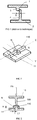
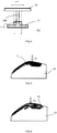
- a relative sliding between the ice 2 and the base 1 at their respective welding beads 4, 3 is likely to appear fortuitously, breaking the parallelism situation of the base 1 with respect to the ice 2. This results in a risk of breakage of the ice 2 and / or the base 1, a risk of poor welding, even fragile.
- the base 1 is attached to the window 2 in a position not corresponding at all to the expected position, having a shift D or lack of parallelism, involving a risk of scrapping for no -conformity of the luminous device.
- JP 2000 025116 discloses an alternative method for aligning the weld beads vis-à-vis during mirror heating operations and then pressing. This method uses specific clamping tools for the hollow bodies to be welded.
- the object of the present invention is to provide a solution for assembling by mirror welding two pieces together of a light device for a motor vehicle that overcomes the disadvantages listed above.
- the subject of the invention is a method of assembling them by mirror welding of a first part and a second part of a part.
- luminous device for a motor vehicle comprising a step of supplying the first and second parts where each part comprises, in its zone of contact interface with the other part, a weld bead intended to come into contact with the weld bead of the other piece during the mirror welding.
- the weld bead of at least one of said first and second parts is provided with a plurality of enlarging ribs spaced along the length of said weld seam, each expanding rib being configured so locally expanding the width of the weld bead relative to the width of the weld bead outside the areas where the widening ribs are present.
- expanding ribs are arranged on either side of the weld bead with respect to its direction of extension.
- two widening ribs are arranged locally perpendicularly or at an angle to the direction of extension of the weld bead, in alignment with one another, so as to form a cross together with said weld bead .
- two widening ribs respectively extending on one side and the other of the weld bead are shifted together along the length of the weld bead according to a staggered organization.
- each widening rib extends over a length of between 1.5 mm and 4 mm from the weld bead.
- the height of each widening rib is greater than or equal to the height of the weld bead, counted from the face of the piece from which the widening rib is born.
- each widening rib is shaped so that its height tends to increase away from the weld bead.
- said method comprises a first step of contacting the first and second parts at their weld seams, in which the widening ribs of each piece which is equipped with them. participate in the positioning of the weld bead of the other piece and the spatial conformation of said other piece, and a mirror welding step of the first part and second part between them at their weld seams and widening ribs.
- the part whose weld seam comprises the widening ribs is supported by a lower tool and in that the mirror welding step comprises a step of gripping the pre-centered part during the first step of contacting by a superior tool, the centering and the spatial conformation of said other part being obtained by the widening ribs of the part whose weld bead is equipped during the gripping step.
- the first contacting step comprises a step of manually placing said other part on the part whose weld bead is equipped with widening ribs.
- the mirror welding step comprises, following the gripping step, a step of relative displacement between the upper and lower tools so as to remove the first and second parts of each other, a step of at least partial softening of each weld bead of the first and second parts by a heating mirror, then a second step of contacting by pressure of the first and second parts to level of their weld seams still at least partially softened.
- the first and second parts are configured to form, after the mirror weld, a light device of the motor vehicle signaling device type, for example a rear signaling light, one of the first and second parts, particularly the piece whose weld seam is equipped with the widening ribs, being constituted by a base, and the other of the first and second parts being constituted by an ice at least partially transparent to light.
- a light device of the motor vehicle signaling device type for example a rear signaling light
- one of the first and second parts, particularly the piece whose weld seam is equipped with the widening ribs being constituted by a base
- the other of the first and second parts being constituted by an ice at least partially transparent to light.
- the method comprises a step of supplying the first and second parts 10, 11 where each part 10, 11 comprises, in its contact interface zone with the other part, a weld bead, respectively 100, 110, intended to come in contact against the weld bead of the other part during the mirror welding.
- Mirror welding is also known as hot blade welding.
- This technique consists in positioning the two parts 10, 11, which are preferably formed in a suitable plastic material at least in the region of the weld beads 100, 110, one above the other leaving a space between those for example about 50 cm. Then, a mirror, for example a heating blade, which heats on two opposite sides is introduced into this space. The two parts 10, 11 then come into contact with the mirror or are placed near it (mirror with infrared or hot gas) at the weld seams 100, 110 until the temperature of the material of each piece 10, 11, at the weld bead 100, 110 has reached its surface softening temperature.
- the weld bead 110 of at least one of the first and second parts 10, 11 (for example only the weld bead 110 of the second part 11) is provided with a plurality of widening ribs N staggered along the length (counted along its extension length X along which it extends) of said weld bead 110.
- Each enlargement rib N is configured to locally expand the width of the weld bead 110 relative to the width L of the weld bead 110 outside the areas where the widening ribs N are present (see the illustration on FIG. figure 2 for example).
- the light device obtained by assembling the parts 10, 11 may equally be of the motor vehicle signaling device type, for example a rear signaling light, or else of the external lighting device of the motor vehicle or of the device type. 'interior lighting of the motor vehicle.
- the first and second parts 10, 11 are configured to form, after the mirror weld, a light device of the motor vehicle signaling device type, for example a rear signaling light, one 11 of the first and second parts 10, 11, in particular the part 11 whose weld seam 110 is equipped with enlarging ribs N, consisting of a base of the device signaling, and the other 10 first and second parts 10, 11 being constituted by an ice of the signaling device, at least partially transparent to light.
- the piece provided with enlarging ribs N is the second piece 11 and the weld bead concerned is the weld bead identified 110.
- the piece provided with ribs N wideners may be the first piece 10 and the weld bead concerned is in this case the weld seam identified 100.
- the two weld seams 100, 110 of the two parts 10, 11 may simultaneously be equipped with widening ribs, or well it can be expected that only one of the two welding seams 100, 110 is equipped with such ribs N.
- expanding ribs N are disposed on either side of the weld bead 110 with respect to its extension direction X, which corresponds to the lateral direction marked Y.
- the widening ribs N which equip the same weld bead are all arranged on the same side of the weld bead seen in the Y direction.
- Two enlarging ribs N are arranged locally perpendicularly (which is the case shown) or on the spur (situation not shown) with respect to the extension direction X of the weld bead 110, in alignment with one another , so as to constitute a brace ( figure 2 ) together with the weld bead 110 equipped with these ribs N.
- two widening ribs N respectively extending on one side and the other of the weld bead 110 in the direction Y, are shifted together along the length (ie in the direction of extension X) of the weld bead 110 according to a staggered organization.
- a possible dimensioning which gives complete satisfaction for the desired function in particular in the case of a first piece 10 consisting of an ice and a second piece 11 constituted by a base of the same signaling device, provides that each enlargement rib N extends over a length L1 (visible on the figure 3 ) between 1.5 mm and 4 mm, preferably between 1.5 and 2.5 mm, from the weld bead 110 from which it originates.
- each enlarging rib N is greater than or equal to the height of the weld bead 110, these two heights being counted from the face of the workpiece 11 from which the widening rib N originates.
- each enlarging rib N is shaped so that its height H tends to increase away from the weld bead 110, making it possible to create a local funnel shape that can participate in the centering (For setting up and maintaining the positioning of the other weld seam 100).
- the height of the widening rib N is constant over its length.
- the part 11 whose weld bead 110 comprises the widening ribs N is preferably supported by a lower tool O ( figure 5 ).
- the mirror welding step then comprises a gripping step F3 ( figure 7 ) of the pre-centered part 10 during the first contacting step F1, F2 by an upper tool OS.
- the centering and the spatial conformation of the said other part are very advantageously maintained during the gripping step F3 and greatly facilitated by the widening ribs N of the part of which the weld bead 110 is equipped with (here constituted by the second piece 11) and on which it rests.
- the first contacting step F1, F2 comprises a step of manually placing said other piece (here constituted by the first piece 10) on the piece (here constituted by the second piece 11). whose weld seam 110 is equipped with enlarging ribs N.
- the mirror welding step comprises, following the gripping step F3, a relative displacement step F4 between the upper and lower tools OS, OI so as to move the first and second parts 10, 11 away from each other. the other, a step of at least partial softening or at least partial melting of each weld bead 100, 110 of the first and second parts 10, 11 by a heating mirror, then a second press-contacting step of the first and second parts 10, 11 at their weld seams 100, 110 still at least partially softened.
- the second piece 11 the weld seam 110 of which is equipped with the widening ribs N, remains integral with the lower tool OI while the other piece, here the first piece 10 which is, for example, devoid of widening rib N although it could indifferently include in complement or substitution of those of the second piece 11, remains secured to the upper tool OS after its gripping F3 by the latter.
- the relative displacement F4 is for example obtained by an upward movement of the upper tool OS while the lower tool OI remains fixed. Conversely, the relative displacement F4 could be obtained by a displacement towards the bottom of the lower tool OI while the upper tool OS would remain fixed.
- the part 11 is first manually deposited on the lower tool OI (arrow F1), then the other part 10 is placed manually on the part 11 (arrow F2) to create a first contact between the pieces 10, 11, then the piece 10 is grasped by the upper tool OS (arrow F3) during the gripping step, then the piece 10 thus grasped is moved relative to the piece 11 via at least one of the tools OI and OS, then the mirror welding step is finalized by a second pressurized contact parts 10, 11 at a time when the weld seams 110, 100 are still in the state softened after heating by the mirror or heating blade.
- the widening ribs N added locally in the width of the weld bead 110 allow easy manual pre-positioning of the parts 10, 11 by the operator. They also make it possible to accept the manufacturing dispersions of the parts 10, 11.
- the widening ribs allow the two parts 10, 11 to slide relative to each other, and thus to center and conform the part 10 by the through the mirror welding process itself to ensure proper positioning of the parts 10, 11 during their assembly.
- the figure 5 schematizes the sliding tolerance E1 of the parts 10, 11 relative to each other, in which the part 10 is nevertheless maintained in the centering position and shaped spatially via the expanding ribs N of the part 11. This value of E1 is directly related to the total width E2 of the weld bead 110 at the widening ribs N which equip it and to the width of the weld bead 100.
- Another advantage of the expanding ribs N is an improvement in the ergonomics of the workstation in which the assembly process is carried out. This allows to manually load the workpiece 11, even if it has a high weight, in the lower part of the machine (more precisely on the lower tool OI) and position the workpiece 10 on the previously loaded workpiece 11. Unlike the prior art, there is no effort to exercise to conform the piece 10 and to fix the piece 10 which is potentially heavy above the shoulders of the operator.
Landscapes
- Engineering & Computer Science (AREA)
- Mechanical Engineering (AREA)
- General Engineering & Computer Science (AREA)
- Physics & Mathematics (AREA)
- Thermal Sciences (AREA)
- Lining Or Joining Of Plastics Or The Like (AREA)
- Rear-View Mirror Devices That Are Mounted On The Exterior Of The Vehicle (AREA)
Claims (12)
- Verfahren zum Fügen eines ersten Teils (10) und eines zweiten Teils (11) einer Beleuchtungseinrichtung für Kraftfahrzeuge untereinander durch Spiegelschweißen, umfassend einen Schritt des Bereitstellens der ersten und zweiten Teile (10, 11), wobei jedes Teil (10, 11) in seiner Kontaktgrenzfläche zum anderen Teil eine Schweißraupe (100, 110) umfasst, die dazu bestimmt ist, während des Spiegelschweißens mit der Schweißraupe des anderen Teils in Kontakt zu gelangen, dadurch gekennzeichnet, dass die Schweißraupe (110) von mindestens einem (11) der ersten und zweiten Teile (10, 11) mit einer Vielzahl von Expanderrippen (N) versehen ist, die entlang der Länge der Schweißraupe (110) gestaffelt sind, wobei jede Expanderrippe (N) so gestaltet ist, dass sie die Breite der Schweißraupe (110) in Bezug auf die Breite (L) der Schweißraupe (110) außerhalb der Bereiche, in denen die Expanderrippen (N) vorhanden sind, lokal verbreitert.
- Fügeverfahren nach Anspruch 1, dadurch gekennzeichnet, dass Expanderrippen (N) bei der damit ausgestatteten Schweißraupe (110) beidseits der Schweißraupe (110) in Bezug auf deren Ausdehnungsrichtung (X) angeordnet sind.
- Fügeverfahren nach Anspruch 2, dadurch gekennzeichnet, dass zwei Expanderrippen (N) lokal rechtwinklig oder ährenförmig in Bezug auf die Ausdehnungsrichtung (X) der Schweißraupe (110) fluchtend miteinander angeordnet sind, so dass sie gemeinsam mit der Schweißraupe (110) ein Kreuz bilden.
- Fügeverfahren nach einem der Ansprüche 2 oder 3, dadurch gekennzeichnet, dass zwei Expanderrippen (N), die sich jeweils auf der einen und der anderen Seite der Schweißraupe (110) erstrecken, untereinander entlang der Länge der Schweißraupe (110) gemäß einer Zickzackanordnung versetzt sind.
- Fügeverfahren nach einem der Ansprüche 1 bis 4, dadurch gekennzeichnet, dass sich jede Expanderrippe (N) von der Schweißraupe (110) aus über eine Länge (L1) zwischen 1,5 mm und 4 mm erstreckt.
- Fügeverfahren nach einem der Ansprüche 1 bis 5, dadurch gekennzeichnet, dass die Höhe (H) jeder Expanderrippe (N), gerechnet von der Fläche des Teils (11) aus, an der die Expanderrippe (N) ihren Anfangspunkt hat, größer oder gleich der Höhe der Schweißraupe (110) ist.
- Fügeverfahren nach Anspruch 6, dadurch gekennzeichnet, dass jede Expanderrippe (N) so ausgebildet ist, dass ihre Höhe (H) dazu tendiert, mit zunehmender Entfernung von der Schweißraupe (110) zuzunehmen.
- Fügeverfahren nach einem der Ansprüche 1 bis 7, dadurch gekennzeichnet, dass es nach dem Schritt des Bereitstellens einen ersten Schritt des Kontaktierens (F1, F2) der ersten und zweiten Teile (10, 11) an ihren Schweißraupen (100, 110), wobei die Expanderrippen (N) jedes damit ausgestatteten Teils (11) zur Positionierung der Schweißraupe (100) des anderen Teils (10) und zur räumlichen Konfiguration des anderen Teils (10) beitragen, und dann einen Schritt des Spiegelschweißens des ersten Teils (10) und zweiten Teils (11) untereinander an ihren Schweißraupen (100, 110) und den Expanderrippen (N) umfasst.
- Fügeverfahren nach Anspruch 8, dadurch gekennzeichnet, dass während des ersten Schritts des Kontaktierens (F1, F2) das Teil (11), dessen Schweißraupe (110) die Expanderrippen (N) umfasst, durch ein unteres Werkzeug (OI) gestützt wird, und dass der Schritt des Spiegelschweißens einen Schritt des Greifens (F3) des während des ersten Schritts des Kontaktierens (F1, F2) vorzentrierten Teils (10) durch ein oberes Werkzeug (OS) umfasst, wobei das Zentrieren und die räumliche Konfiguration des anderen Teils (10) durch die Expanderrippen (N) des Teils (11), dessen Schweißraupe (110) damit ausgestattet ist, während des Schritts des Greifens (F3) erhalten werden.
- Fügeverfahren nach einem der Ansprüche 8 oder 9, dadurch gekennzeichnet, dass der erste Schritt des Kontaktierens (F1, F2) einen Schritt des manuellen Einrichtens (F2) des anderen Teils (10) an dem Teil (11), dessen Schweißraupe (110) mit Expanderrippen (N) ausgestattet ist, umfasst.
- Fügeverfahren nach einem der Ansprüche 9 oder 10, dadurch gekennzeichnet, dass der Schritt des Spiegelschweißens nach dem Schritt des Greifens (F3) einen Schritt des Bewegens (F4) der oberen und unteren Werkzeuge (OS, OI) relativ zueinander, so dass die ersten und zweiten Teile (10, 11) voneinander entfernt werden, einen Schritt des zumindest teilweisen Erweichens jeder Schweißraupe (100, 110) der ersten und zweiten Teile (10, 11) durch einen Heizspiegel und dann einen zweiten Schritt des Kontaktierens durch Pressen der ersten und zweiten Teile (10, 11) an ihren noch zumindest teilweise erweichten Schweißnähten (100, 110) umfasst.
- Fügeverfahren nach einem der Ansprüche 1 bis 11, dadurch gekennzeichnet, dass die ersten und zweiten Teile (10, 11) so gestaltet sind, dass sie nach dem Spiegelschweißen eine Beleuchtungseinrichtung von der Art einer Signalleuchte eines Kraftfahrzeugs, beispielsweise eine Hecksignalleuchte, bilden, wobei das eine (11) der ersten und zweiten Teile (10, 11), insbesondere das Teil, dessen Schweißraupe (110) mit Expanderrippen (N) ausgestattet ist, aus einem Sockel gebildet ist und das andere (10) der ersten und zweiten Teile (10, 11) aus einer zumindest teilweise lichtdurchlässigen Glasscheibe gebildet ist.
Applications Claiming Priority (2)
| Application Number | Priority Date | Filing Date | Title |
|---|---|---|---|
| FR1459272A FR3026343B1 (fr) | 2014-09-30 | 2014-09-30 | Assemblage de deux pieces d'un dispositif lumineux par soudure miroir via des nervures elargisseurs |
| PCT/EP2015/072168 WO2016050652A1 (fr) | 2014-09-30 | 2015-09-25 | Assemblage de deux pièces d'un dispositif lumineux par soudure miroir via des nervures élargisseurs |
Publications (2)
| Publication Number | Publication Date |
|---|---|
| EP3200971A1 EP3200971A1 (de) | 2017-08-09 |
| EP3200971B1 true EP3200971B1 (de) | 2018-10-10 |
Family
ID=51842660
Family Applications (1)
| Application Number | Title | Priority Date | Filing Date |
|---|---|---|---|
| EP15770880.1A Active EP3200971B1 (de) | 2014-09-30 | 2015-09-25 | Zweiteilige anordnung einer beleuchtungsvorrichtung durch spiegelschweissen über expanderrippen |
Country Status (5)
| Country | Link |
|---|---|
| US (1) | US10486366B2 (de) |
| EP (1) | EP3200971B1 (de) |
| CN (1) | CN107073828B (de) |
| FR (1) | FR3026343B1 (de) |
| WO (1) | WO2016050652A1 (de) |
Families Citing this family (1)
| Publication number | Priority date | Publication date | Assignee | Title |
|---|---|---|---|---|
| CN112976591B (zh) * | 2021-02-18 | 2022-11-22 | 烟台佳合塑胶科技有限公司 | 一种高刚性塑料制品加工工艺 |
Family Cites Families (10)
| Publication number | Priority date | Publication date | Assignee | Title |
|---|---|---|---|---|
| JP3328166B2 (ja) * | 1997-06-12 | 2002-09-24 | 株式会社小糸製作所 | 車両用灯具の振動溶着方法及びその振動溶着装置 |
| JP2000025116A (ja) * | 1998-07-10 | 2000-01-25 | Takagi Seiko Corp | 熱板溶着方法とそれに要する受治具 |
| JP4021120B2 (ja) * | 2000-04-13 | 2007-12-12 | 株式会社小糸製作所 | 車両用灯具の製造装置 |
| JP3913459B2 (ja) * | 2000-11-13 | 2007-05-09 | 株式会社小糸製作所 | 車両用灯具の製造方法 |
| JP2004345094A (ja) * | 2003-05-20 | 2004-12-09 | Koito Mfg Co Ltd | 車両用灯具の製造装置 |
| JP4566613B2 (ja) * | 2004-04-28 | 2010-10-20 | キヤノン株式会社 | レンズ固定方法 |
| JP4757226B2 (ja) * | 2007-05-16 | 2011-08-24 | カルソニックカンセイ株式会社 | 振動溶着部構造 |
| DE102010017796A1 (de) * | 2009-07-30 | 2011-02-17 | Kobayashi Industrial Co., Ltd., Fujinomiya | Harzbauteil-Schweissvorrichtung und Verfahren zum Verschweissen von Harzbauteilen |
| US20130157015A1 (en) * | 2011-12-20 | 2013-06-20 | GM Global Technology Operations LLC | Precisely Locating Components in an Infrared Welded Assembly |
| JP2014063653A (ja) * | 2012-09-21 | 2014-04-10 | Isuzu Motors Ltd | ランプの製造方法 |
-
2014
- 2014-09-30 FR FR1459272A patent/FR3026343B1/fr active Active
-
2015
- 2015-09-25 WO PCT/EP2015/072168 patent/WO2016050652A1/fr not_active Ceased
- 2015-09-25 US US15/515,921 patent/US10486366B2/en active Active
- 2015-09-25 EP EP15770880.1A patent/EP3200971B1/de active Active
- 2015-09-25 CN CN201580053149.9A patent/CN107073828B/zh active Active
Non-Patent Citations (1)
| Title |
|---|
| None * |
Also Published As
| Publication number | Publication date |
|---|---|
| FR3026343B1 (fr) | 2016-10-28 |
| EP3200971A1 (de) | 2017-08-09 |
| CN107073828A (zh) | 2017-08-18 |
| CN107073828B (zh) | 2019-04-26 |
| US10486366B2 (en) | 2019-11-26 |
| FR3026343A1 (fr) | 2016-04-01 |
| WO2016050652A1 (fr) | 2016-04-07 |
| US20170305072A1 (en) | 2017-10-26 |
Similar Documents
| Publication | Publication Date | Title |
|---|---|---|
| EP2195135B1 (de) | Schweissverfahren zum reibrührschweissen von teilen unter verwendung eines doppelt geschulterten schweissgerät es | |
| FR2785043A1 (fr) | Condenseur brase destine a un systeme de climatisation | |
| EP2566683B1 (de) | Vorrichtung zur montage zweier teile aus thermoplastischen materialien mit lasertransparentem schweissen und zugehöriges montageverfahren | |
| FR2694514A1 (fr) | Procédé de soudage bord à bord d'au moins deux tôles. | |
| EP2111333B1 (de) | Verfahren zur fixierung erster und zweiter thermoplastischer teile | |
| EP3200971B1 (de) | Zweiteilige anordnung einer beleuchtungsvorrichtung durch spiegelschweissen über expanderrippen | |
| EP2408585B1 (de) | Lötschweissvorrichtung | |
| WO2014097043A1 (fr) | Procédé et moule pour le soudage des extrémités de deux portions de rail | |
| EP1854707A1 (de) | Anschlussstück für einen Längsträger für ein Kraftfahrzeug und Längsträger, der ein solches Anschlussstück umfasst | |
| FR2709083A1 (fr) | Flan de tôle de structure multicouche à soudabilité et à emboutissabilité améliorée et procédé et dispositif de fabrication de ce type de flans de tôle. | |
| FR2713740A1 (fr) | Procédé de fixation d'une bague d'arrêt à un embout mâle d'un tuyau. | |
| FR3094245A1 (fr) | Procédé et outillage pour la mise en forme d’une arête sur un embouti | |
| EP3130412B1 (de) | Werkzeug zum tiefziehen mit spannungsloser führung | |
| FR2983768A1 (fr) | Embout de bridage equipe d'un accessoire de bridage pour un dispositif d'assemblage deux pieces par soudage laser par transparence et procede de remplacement d'un tel accessoire | |
| EP1164346A1 (de) | Dichtungshülse zum Erzielen einer dichten Verbindung zwischen zwei flachen paralellen Wänden aus dünnwandinem Blech | |
| FR3040907A1 (fr) | Profile soudable et procede associe, pour la soudure de panneaux en materiau plastique | |
| FR3141359A1 (fr) | Procédé de soudage par friction malaxage et ensemble de soudage associé | |
| EP1935615A1 (de) | Verfahren zur Verbindung eines ersten und zweiten Teils aus thermoplastischem Material | |
| FR3059590A1 (fr) | Installation et procede de soudage par vibration | |
| EP3144126A1 (de) | Schweissbares profil und entsprechendes verfahren zum verschweissen von platten aus kunststoffmaterial | |
| FR3003491A1 (fr) | Soudage de feuillures aluminium par bossage. | |
| FR2793433A1 (fr) | Procede d'assemblage par soudage d'un element creux en aluminium de carrosserie automobile, et element creux assemble selon le procede | |
| FR3046738A1 (fr) | Procede et dispositif d'assemblage par soudage laser par transparence d'une premiere piece comprenant au moins un element de liaison avec une deuxieme piece | |
| FR2737143A1 (fr) | Procede et dispositif pour decouper au moyen d'une presse la paroi peripherique tubulaire d'un organe en forme de bol | |
| FR2958571A1 (fr) | Procede d'assemblage de deux pieces en tole par soudo-brasage. |
Legal Events
| Date | Code | Title | Description |
|---|---|---|---|
| STAA | Information on the status of an ep patent application or granted ep patent |
Free format text: STATUS: THE INTERNATIONAL PUBLICATION HAS BEEN MADE |
|
| PUAI | Public reference made under article 153(3) epc to a published international application that has entered the european phase |
Free format text: ORIGINAL CODE: 0009012 |
|
| STAA | Information on the status of an ep patent application or granted ep patent |
Free format text: STATUS: REQUEST FOR EXAMINATION WAS MADE |
|
| 17P | Request for examination filed |
Effective date: 20170328 |
|
| AK | Designated contracting states |
Kind code of ref document: A1 Designated state(s): AL AT BE BG CH CY CZ DE DK EE ES FI FR GB GR HR HU IE IS IT LI LT LU LV MC MK MT NL NO PL PT RO RS SE SI SK SM TR |
|
| AX | Request for extension of the european patent |
Extension state: BA ME |
|
| DAV | Request for validation of the european patent (deleted) | ||
| DAX | Request for extension of the european patent (deleted) | ||
| GRAP | Despatch of communication of intention to grant a patent |
Free format text: ORIGINAL CODE: EPIDOSNIGR1 |
|
| STAA | Information on the status of an ep patent application or granted ep patent |
Free format text: STATUS: GRANT OF PATENT IS INTENDED |
|
| RIC1 | Information provided on ipc code assigned before grant |
Ipc: F21S 43/20 20180101ALI20180412BHEP Ipc: B29C 65/78 20060101ALI20180412BHEP Ipc: F21S 43/27 20180101ALI20180412BHEP Ipc: B29C 65/20 20060101AFI20180412BHEP |
|
| INTG | Intention to grant announced |
Effective date: 20180516 |
|
| GRAS | Grant fee paid |
Free format text: ORIGINAL CODE: EPIDOSNIGR3 |
|
| GRAA | (expected) grant |
Free format text: ORIGINAL CODE: 0009210 |
|
| STAA | Information on the status of an ep patent application or granted ep patent |
Free format text: STATUS: THE PATENT HAS BEEN GRANTED |
|
| AK | Designated contracting states |
Kind code of ref document: B1 Designated state(s): AL AT BE BG CH CY CZ DE DK EE ES FI FR GB GR HR HU IE IS IT LI LT LU LV MC MK MT NL NO PL PT RO RS SE SI SK SM TR |
|
| REG | Reference to a national code |
Ref country code: GB Ref legal event code: FG4D Free format text: NOT ENGLISH |
|
| REG | Reference to a national code |
Ref country code: AT Ref legal event code: REF Ref document number: 1050714 Country of ref document: AT Kind code of ref document: T Effective date: 20181015 Ref country code: CH Ref legal event code: EP |
|
| REG | Reference to a national code |
Ref country code: IE Ref legal event code: FG4D Free format text: LANGUAGE OF EP DOCUMENT: FRENCH |
|
| REG | Reference to a national code |
Ref country code: DE Ref legal event code: R096 Ref document number: 602015017970 Country of ref document: DE |
|
| REG | Reference to a national code |
Ref country code: NL Ref legal event code: FP |
|
| REG | Reference to a national code |
Ref country code: LT Ref legal event code: MG4D |
|
| REG | Reference to a national code |
Ref country code: AT Ref legal event code: MK05 Ref document number: 1050714 Country of ref document: AT Kind code of ref document: T Effective date: 20181010 |
|
| PG25 | Lapsed in a contracting state [announced via postgrant information from national office to epo] |
Ref country code: HR Free format text: LAPSE BECAUSE OF FAILURE TO SUBMIT A TRANSLATION OF THE DESCRIPTION OR TO PAY THE FEE WITHIN THE PRESCRIBED TIME-LIMIT Effective date: 20181010 Ref country code: BG Free format text: LAPSE BECAUSE OF FAILURE TO SUBMIT A TRANSLATION OF THE DESCRIPTION OR TO PAY THE FEE WITHIN THE PRESCRIBED TIME-LIMIT Effective date: 20190110 Ref country code: FI Free format text: LAPSE BECAUSE OF FAILURE TO SUBMIT A TRANSLATION OF THE DESCRIPTION OR TO PAY THE FEE WITHIN THE PRESCRIBED TIME-LIMIT Effective date: 20181010 Ref country code: IS Free format text: LAPSE BECAUSE OF FAILURE TO SUBMIT A TRANSLATION OF THE DESCRIPTION OR TO PAY THE FEE WITHIN THE PRESCRIBED TIME-LIMIT Effective date: 20190210 Ref country code: LT Free format text: LAPSE BECAUSE OF FAILURE TO SUBMIT A TRANSLATION OF THE DESCRIPTION OR TO PAY THE FEE WITHIN THE PRESCRIBED TIME-LIMIT Effective date: 20181010 Ref country code: NO Free format text: LAPSE BECAUSE OF FAILURE TO SUBMIT A TRANSLATION OF THE DESCRIPTION OR TO PAY THE FEE WITHIN THE PRESCRIBED TIME-LIMIT Effective date: 20190110 Ref country code: PL Free format text: LAPSE BECAUSE OF FAILURE TO SUBMIT A TRANSLATION OF THE DESCRIPTION OR TO PAY THE FEE WITHIN THE PRESCRIBED TIME-LIMIT Effective date: 20181010 Ref country code: ES Free format text: LAPSE BECAUSE OF FAILURE TO SUBMIT A TRANSLATION OF THE DESCRIPTION OR TO PAY THE FEE WITHIN THE PRESCRIBED TIME-LIMIT Effective date: 20181010 Ref country code: AT Free format text: LAPSE BECAUSE OF FAILURE TO SUBMIT A TRANSLATION OF THE DESCRIPTION OR TO PAY THE FEE WITHIN THE PRESCRIBED TIME-LIMIT Effective date: 20181010 Ref country code: LV Free format text: LAPSE BECAUSE OF FAILURE TO SUBMIT A TRANSLATION OF THE DESCRIPTION OR TO PAY THE FEE WITHIN THE PRESCRIBED TIME-LIMIT Effective date: 20181010 |
|
| PG25 | Lapsed in a contracting state [announced via postgrant information from national office to epo] |
Ref country code: PT Free format text: LAPSE BECAUSE OF FAILURE TO SUBMIT A TRANSLATION OF THE DESCRIPTION OR TO PAY THE FEE WITHIN THE PRESCRIBED TIME-LIMIT Effective date: 20190210 Ref country code: SE Free format text: LAPSE BECAUSE OF FAILURE TO SUBMIT A TRANSLATION OF THE DESCRIPTION OR TO PAY THE FEE WITHIN THE PRESCRIBED TIME-LIMIT Effective date: 20181010 Ref country code: AL Free format text: LAPSE BECAUSE OF FAILURE TO SUBMIT A TRANSLATION OF THE DESCRIPTION OR TO PAY THE FEE WITHIN THE PRESCRIBED TIME-LIMIT Effective date: 20181010 Ref country code: RS Free format text: LAPSE BECAUSE OF FAILURE TO SUBMIT A TRANSLATION OF THE DESCRIPTION OR TO PAY THE FEE WITHIN THE PRESCRIBED TIME-LIMIT Effective date: 20181010 Ref country code: GR Free format text: LAPSE BECAUSE OF FAILURE TO SUBMIT A TRANSLATION OF THE DESCRIPTION OR TO PAY THE FEE WITHIN THE PRESCRIBED TIME-LIMIT Effective date: 20190111 |
|
| REG | Reference to a national code |
Ref country code: DE Ref legal event code: R097 Ref document number: 602015017970 Country of ref document: DE |
|
| PG25 | Lapsed in a contracting state [announced via postgrant information from national office to epo] |
Ref country code: CZ Free format text: LAPSE BECAUSE OF FAILURE TO SUBMIT A TRANSLATION OF THE DESCRIPTION OR TO PAY THE FEE WITHIN THE PRESCRIBED TIME-LIMIT Effective date: 20181010 Ref country code: IT Free format text: LAPSE BECAUSE OF FAILURE TO SUBMIT A TRANSLATION OF THE DESCRIPTION OR TO PAY THE FEE WITHIN THE PRESCRIBED TIME-LIMIT Effective date: 20181010 Ref country code: DK Free format text: LAPSE BECAUSE OF FAILURE TO SUBMIT A TRANSLATION OF THE DESCRIPTION OR TO PAY THE FEE WITHIN THE PRESCRIBED TIME-LIMIT Effective date: 20181010 |
|
| PLBE | No opposition filed within time limit |
Free format text: ORIGINAL CODE: 0009261 |
|
| STAA | Information on the status of an ep patent application or granted ep patent |
Free format text: STATUS: NO OPPOSITION FILED WITHIN TIME LIMIT |
|
| PG25 | Lapsed in a contracting state [announced via postgrant information from national office to epo] |
Ref country code: SK Free format text: LAPSE BECAUSE OF FAILURE TO SUBMIT A TRANSLATION OF THE DESCRIPTION OR TO PAY THE FEE WITHIN THE PRESCRIBED TIME-LIMIT Effective date: 20181010 Ref country code: SM Free format text: LAPSE BECAUSE OF FAILURE TO SUBMIT A TRANSLATION OF THE DESCRIPTION OR TO PAY THE FEE WITHIN THE PRESCRIBED TIME-LIMIT Effective date: 20181010 Ref country code: EE Free format text: LAPSE BECAUSE OF FAILURE TO SUBMIT A TRANSLATION OF THE DESCRIPTION OR TO PAY THE FEE WITHIN THE PRESCRIBED TIME-LIMIT Effective date: 20181010 Ref country code: RO Free format text: LAPSE BECAUSE OF FAILURE TO SUBMIT A TRANSLATION OF THE DESCRIPTION OR TO PAY THE FEE WITHIN THE PRESCRIBED TIME-LIMIT Effective date: 20181010 |
|
| 26N | No opposition filed |
Effective date: 20190711 |
|
| PG25 | Lapsed in a contracting state [announced via postgrant information from national office to epo] |
Ref country code: SI Free format text: LAPSE BECAUSE OF FAILURE TO SUBMIT A TRANSLATION OF THE DESCRIPTION OR TO PAY THE FEE WITHIN THE PRESCRIBED TIME-LIMIT Effective date: 20181010 |
|
| PG25 | Lapsed in a contracting state [announced via postgrant information from national office to epo] |
Ref country code: TR Free format text: LAPSE BECAUSE OF FAILURE TO SUBMIT A TRANSLATION OF THE DESCRIPTION OR TO PAY THE FEE WITHIN THE PRESCRIBED TIME-LIMIT Effective date: 20181010 |
|
| PG25 | Lapsed in a contracting state [announced via postgrant information from national office to epo] |
Ref country code: MC Free format text: LAPSE BECAUSE OF FAILURE TO SUBMIT A TRANSLATION OF THE DESCRIPTION OR TO PAY THE FEE WITHIN THE PRESCRIBED TIME-LIMIT Effective date: 20181010 |
|
| REG | Reference to a national code |
Ref country code: CH Ref legal event code: PL |
|
| PG25 | Lapsed in a contracting state [announced via postgrant information from national office to epo] |
Ref country code: LU Free format text: LAPSE BECAUSE OF NON-PAYMENT OF DUE FEES Effective date: 20190925 Ref country code: CH Free format text: LAPSE BECAUSE OF NON-PAYMENT OF DUE FEES Effective date: 20190930 Ref country code: IE Free format text: LAPSE BECAUSE OF NON-PAYMENT OF DUE FEES Effective date: 20190925 Ref country code: LI Free format text: LAPSE BECAUSE OF NON-PAYMENT OF DUE FEES Effective date: 20190930 |
|
| REG | Reference to a national code |
Ref country code: BE Ref legal event code: MM Effective date: 20190930 |
|
| PG25 | Lapsed in a contracting state [announced via postgrant information from national office to epo] |
Ref country code: BE Free format text: LAPSE BECAUSE OF NON-PAYMENT OF DUE FEES Effective date: 20190930 |
|
| GBPC | Gb: european patent ceased through non-payment of renewal fee |
Effective date: 20190925 |
|
| PG25 | Lapsed in a contracting state [announced via postgrant information from national office to epo] |
Ref country code: GB Free format text: LAPSE BECAUSE OF NON-PAYMENT OF DUE FEES Effective date: 20190925 |
|
| PG25 | Lapsed in a contracting state [announced via postgrant information from national office to epo] |
Ref country code: CY Free format text: LAPSE BECAUSE OF FAILURE TO SUBMIT A TRANSLATION OF THE DESCRIPTION OR TO PAY THE FEE WITHIN THE PRESCRIBED TIME-LIMIT Effective date: 20181010 |
|
| PG25 | Lapsed in a contracting state [announced via postgrant information from national office to epo] |
Ref country code: MT Free format text: LAPSE BECAUSE OF FAILURE TO SUBMIT A TRANSLATION OF THE DESCRIPTION OR TO PAY THE FEE WITHIN THE PRESCRIBED TIME-LIMIT Effective date: 20181010 Ref country code: HU Free format text: LAPSE BECAUSE OF FAILURE TO SUBMIT A TRANSLATION OF THE DESCRIPTION OR TO PAY THE FEE WITHIN THE PRESCRIBED TIME-LIMIT; INVALID AB INITIO Effective date: 20150925 |
|
| PG25 | Lapsed in a contracting state [announced via postgrant information from national office to epo] |
Ref country code: MK Free format text: LAPSE BECAUSE OF FAILURE TO SUBMIT A TRANSLATION OF THE DESCRIPTION OR TO PAY THE FEE WITHIN THE PRESCRIBED TIME-LIMIT Effective date: 20181010 |
|
| P01 | Opt-out of the competence of the unified patent court (upc) registered |
Effective date: 20230528 |
|
| PGFP | Annual fee paid to national office [announced via postgrant information from national office to epo] |
Ref country code: DE Payment date: 20250916 Year of fee payment: 11 |
|
| PGFP | Annual fee paid to national office [announced via postgrant information from national office to epo] |
Ref country code: NL Payment date: 20250909 Year of fee payment: 11 |
|
| PGFP | Annual fee paid to national office [announced via postgrant information from national office to epo] |
Ref country code: FR Payment date: 20250929 Year of fee payment: 11 |