EP3200971B1 - Assemblage de deux pièces d'un dispositif lumineux par soudure miroir via des nervures élargisseurs - Google Patents
Assemblage de deux pièces d'un dispositif lumineux par soudure miroir via des nervures élargisseurs Download PDFInfo
- Publication number
- EP3200971B1 EP3200971B1 EP15770880.1A EP15770880A EP3200971B1 EP 3200971 B1 EP3200971 B1 EP 3200971B1 EP 15770880 A EP15770880 A EP 15770880A EP 3200971 B1 EP3200971 B1 EP 3200971B1
- Authority
- EP
- European Patent Office
- Prior art keywords
- weld bead
- expander
- parts
- ribs
- assembly method
- Prior art date
- Legal status (The legal status is an assumption and is not a legal conclusion. Google has not performed a legal analysis and makes no representation as to the accuracy of the status listed.)
- Active
Links
Images

Classifications
-
- B—PERFORMING OPERATIONS; TRANSPORTING
- B29—WORKING OF PLASTICS; WORKING OF SUBSTANCES IN A PLASTIC STATE IN GENERAL
- B29C—SHAPING OR JOINING OF PLASTICS; SHAPING OF MATERIAL IN A PLASTIC STATE, NOT OTHERWISE PROVIDED FOR; AFTER-TREATMENT OF THE SHAPED PRODUCTS, e.g. REPAIRING
- B29C65/00—Joining or sealing of preformed parts, e.g. welding of plastics materials; Apparatus therefor
- B29C65/02—Joining or sealing of preformed parts, e.g. welding of plastics materials; Apparatus therefor by heating, with or without pressure
- B29C65/18—Joining or sealing of preformed parts, e.g. welding of plastics materials; Apparatus therefor by heating, with or without pressure using heated tools
- B29C65/20—Joining or sealing of preformed parts, e.g. welding of plastics materials; Apparatus therefor by heating, with or without pressure using heated tools with direct contact, e.g. using "mirror"
-
- B—PERFORMING OPERATIONS; TRANSPORTING
- B29—WORKING OF PLASTICS; WORKING OF SUBSTANCES IN A PLASTIC STATE IN GENERAL
- B29C—SHAPING OR JOINING OF PLASTICS; SHAPING OF MATERIAL IN A PLASTIC STATE, NOT OTHERWISE PROVIDED FOR; AFTER-TREATMENT OF THE SHAPED PRODUCTS, e.g. REPAIRING
- B29C65/00—Joining or sealing of preformed parts, e.g. welding of plastics materials; Apparatus therefor
- B29C65/02—Joining or sealing of preformed parts, e.g. welding of plastics materials; Apparatus therefor by heating, with or without pressure
- B29C65/18—Joining or sealing of preformed parts, e.g. welding of plastics materials; Apparatus therefor by heating, with or without pressure using heated tools
- B29C65/20—Joining or sealing of preformed parts, e.g. welding of plastics materials; Apparatus therefor by heating, with or without pressure using heated tools with direct contact, e.g. using "mirror"
- B29C65/2053—Joining or sealing of preformed parts, e.g. welding of plastics materials; Apparatus therefor by heating, with or without pressure using heated tools with direct contact, e.g. using "mirror" characterised by special ways of bringing the welding mirrors into position
- B29C65/2061—Joining or sealing of preformed parts, e.g. welding of plastics materials; Apparatus therefor by heating, with or without pressure using heated tools with direct contact, e.g. using "mirror" characterised by special ways of bringing the welding mirrors into position by sliding
- B29C65/2069—Joining or sealing of preformed parts, e.g. welding of plastics materials; Apparatus therefor by heating, with or without pressure using heated tools with direct contact, e.g. using "mirror" characterised by special ways of bringing the welding mirrors into position by sliding with an angle with respect to the plane comprising the parts to be joined
- B29C65/2076—Joining or sealing of preformed parts, e.g. welding of plastics materials; Apparatus therefor by heating, with or without pressure using heated tools with direct contact, e.g. using "mirror" characterised by special ways of bringing the welding mirrors into position by sliding with an angle with respect to the plane comprising the parts to be joined perpendicularly to the plane comprising the parts to be joined
-
- B—PERFORMING OPERATIONS; TRANSPORTING
- B29—WORKING OF PLASTICS; WORKING OF SUBSTANCES IN A PLASTIC STATE IN GENERAL
- B29C—SHAPING OR JOINING OF PLASTICS; SHAPING OF MATERIAL IN A PLASTIC STATE, NOT OTHERWISE PROVIDED FOR; AFTER-TREATMENT OF THE SHAPED PRODUCTS, e.g. REPAIRING
- B29C65/00—Joining or sealing of preformed parts, e.g. welding of plastics materials; Apparatus therefor
- B29C65/02—Joining or sealing of preformed parts, e.g. welding of plastics materials; Apparatus therefor by heating, with or without pressure
- B29C65/18—Joining or sealing of preformed parts, e.g. welding of plastics materials; Apparatus therefor by heating, with or without pressure using heated tools
- B29C65/24—Joining or sealing of preformed parts, e.g. welding of plastics materials; Apparatus therefor by heating, with or without pressure using heated tools characterised by the means for heating the tool
- B29C65/30—Electrical means
-
- B—PERFORMING OPERATIONS; TRANSPORTING
- B29—WORKING OF PLASTICS; WORKING OF SUBSTANCES IN A PLASTIC STATE IN GENERAL
- B29C—SHAPING OR JOINING OF PLASTICS; SHAPING OF MATERIAL IN A PLASTIC STATE, NOT OTHERWISE PROVIDED FOR; AFTER-TREATMENT OF THE SHAPED PRODUCTS, e.g. REPAIRING
- B29C65/00—Joining or sealing of preformed parts, e.g. welding of plastics materials; Apparatus therefor
- B29C65/78—Means for handling the parts to be joined, e.g. for making containers or hollow articles, e.g. means for handling sheets, plates, web-like materials, tubular articles, hollow articles or elements to be joined therewith; Means for discharging the joined articles from the joining apparatus
- B29C65/7802—Positioning the parts to be joined, e.g. aligning, indexing or centring
- B29C65/7805—Positioning the parts to be joined, e.g. aligning, indexing or centring the parts to be joined comprising positioning features
-
- B—PERFORMING OPERATIONS; TRANSPORTING
- B29—WORKING OF PLASTICS; WORKING OF SUBSTANCES IN A PLASTIC STATE IN GENERAL
- B29C—SHAPING OR JOINING OF PLASTICS; SHAPING OF MATERIAL IN A PLASTIC STATE, NOT OTHERWISE PROVIDED FOR; AFTER-TREATMENT OF THE SHAPED PRODUCTS, e.g. REPAIRING
- B29C65/00—Joining or sealing of preformed parts, e.g. welding of plastics materials; Apparatus therefor
- B29C65/78—Means for handling the parts to be joined, e.g. for making containers or hollow articles, e.g. means for handling sheets, plates, web-like materials, tubular articles, hollow articles or elements to be joined therewith; Means for discharging the joined articles from the joining apparatus
- B29C65/7802—Positioning the parts to be joined, e.g. aligning, indexing or centring
- B29C65/7805—Positioning the parts to be joined, e.g. aligning, indexing or centring the parts to be joined comprising positioning features
- B29C65/7814—Positioning the parts to be joined, e.g. aligning, indexing or centring the parts to be joined comprising positioning features in the form of inter-cooperating positioning features, e.g. tenons and mortises
-
- B—PERFORMING OPERATIONS; TRANSPORTING
- B29—WORKING OF PLASTICS; WORKING OF SUBSTANCES IN A PLASTIC STATE IN GENERAL
- B29C—SHAPING OR JOINING OF PLASTICS; SHAPING OF MATERIAL IN A PLASTIC STATE, NOT OTHERWISE PROVIDED FOR; AFTER-TREATMENT OF THE SHAPED PRODUCTS, e.g. REPAIRING
- B29C66/00—General aspects of processes or apparatus for joining preformed parts
- B29C66/01—General aspects dealing with the joint area or with the area to be joined
- B29C66/05—Particular design of joint configurations
- B29C66/10—Particular design of joint configurations particular design of the joint cross-sections
- B29C66/11—Joint cross-sections comprising a single joint-segment, i.e. one of the parts to be joined comprising a single joint-segment in the joint cross-section
- B29C66/114—Single butt joints
- B29C66/1142—Single butt to butt joints
-
- B—PERFORMING OPERATIONS; TRANSPORTING
- B29—WORKING OF PLASTICS; WORKING OF SUBSTANCES IN A PLASTIC STATE IN GENERAL
- B29C—SHAPING OR JOINING OF PLASTICS; SHAPING OF MATERIAL IN A PLASTIC STATE, NOT OTHERWISE PROVIDED FOR; AFTER-TREATMENT OF THE SHAPED PRODUCTS, e.g. REPAIRING
- B29C66/00—General aspects of processes or apparatus for joining preformed parts
- B29C66/01—General aspects dealing with the joint area or with the area to be joined
- B29C66/05—Particular design of joint configurations
- B29C66/301—Three-dimensional joints, i.e. the joined area being substantially non-flat
-
- B—PERFORMING OPERATIONS; TRANSPORTING
- B29—WORKING OF PLASTICS; WORKING OF SUBSTANCES IN A PLASTIC STATE IN GENERAL
- B29C—SHAPING OR JOINING OF PLASTICS; SHAPING OF MATERIAL IN A PLASTIC STATE, NOT OTHERWISE PROVIDED FOR; AFTER-TREATMENT OF THE SHAPED PRODUCTS, e.g. REPAIRING
- B29C66/00—General aspects of processes or apparatus for joining preformed parts
- B29C66/01—General aspects dealing with the joint area or with the area to be joined
- B29C66/05—Particular design of joint configurations
- B29C66/302—Particular design of joint configurations the area to be joined comprising melt initiators
- B29C66/3022—Particular design of joint configurations the area to be joined comprising melt initiators said melt initiators being integral with at least one of the parts to be joined
- B29C66/30223—Particular design of joint configurations the area to be joined comprising melt initiators said melt initiators being integral with at least one of the parts to be joined said melt initiators being rib-like
-
- B—PERFORMING OPERATIONS; TRANSPORTING
- B29—WORKING OF PLASTICS; WORKING OF SUBSTANCES IN A PLASTIC STATE IN GENERAL
- B29C—SHAPING OR JOINING OF PLASTICS; SHAPING OF MATERIAL IN A PLASTIC STATE, NOT OTHERWISE PROVIDED FOR; AFTER-TREATMENT OF THE SHAPED PRODUCTS, e.g. REPAIRING
- B29C66/00—General aspects of processes or apparatus for joining preformed parts
- B29C66/50—General aspects of joining tubular articles; General aspects of joining long products, i.e. bars or profiled elements; General aspects of joining single elements to tubular articles, hollow articles or bars; General aspects of joining several hollow-preforms to form hollow or tubular articles
- B29C66/51—Joining tubular articles, profiled elements or bars; Joining single elements to tubular articles, hollow articles or bars; Joining several hollow-preforms to form hollow or tubular articles
- B29C66/54—Joining several hollow-preforms, e.g. half-shells, to form hollow articles, e.g. for making balls, containers; Joining several hollow-preforms, e.g. half-cylinders, to form tubular articles
-
- B—PERFORMING OPERATIONS; TRANSPORTING
- B29—WORKING OF PLASTICS; WORKING OF SUBSTANCES IN A PLASTIC STATE IN GENERAL
- B29C—SHAPING OR JOINING OF PLASTICS; SHAPING OF MATERIAL IN A PLASTIC STATE, NOT OTHERWISE PROVIDED FOR; AFTER-TREATMENT OF THE SHAPED PRODUCTS, e.g. REPAIRING
- B29C66/00—General aspects of processes or apparatus for joining preformed parts
- B29C66/70—General aspects of processes or apparatus for joining preformed parts characterised by the composition, physical properties or the structure of the material of the parts to be joined; Joining with non-plastics material
- B29C66/73—General aspects of processes or apparatus for joining preformed parts characterised by the composition, physical properties or the structure of the material of the parts to be joined; Joining with non-plastics material characterised by the intensive physical properties of the material of the parts to be joined, by the optical properties of the material of the parts to be joined, by the extensive physical properties of the parts to be joined, by the state of the material of the parts to be joined or by the material of the parts to be joined being a thermoplastic or a thermoset
- B29C66/733—General aspects of processes or apparatus for joining preformed parts characterised by the composition, physical properties or the structure of the material of the parts to be joined; Joining with non-plastics material characterised by the intensive physical properties of the material of the parts to be joined, by the optical properties of the material of the parts to be joined, by the extensive physical properties of the parts to be joined, by the state of the material of the parts to be joined or by the material of the parts to be joined being a thermoplastic or a thermoset characterised by the optical properties of the material of the parts to be joined, e.g. fluorescence, phosphorescence
- B29C66/7336—General aspects of processes or apparatus for joining preformed parts characterised by the composition, physical properties or the structure of the material of the parts to be joined; Joining with non-plastics material characterised by the intensive physical properties of the material of the parts to be joined, by the optical properties of the material of the parts to be joined, by the extensive physical properties of the parts to be joined, by the state of the material of the parts to be joined or by the material of the parts to be joined being a thermoplastic or a thermoset characterised by the optical properties of the material of the parts to be joined, e.g. fluorescence, phosphorescence at least one of the parts to be joined being opaque, transparent or translucent to visible light
- B29C66/73365—General aspects of processes or apparatus for joining preformed parts characterised by the composition, physical properties or the structure of the material of the parts to be joined; Joining with non-plastics material characterised by the intensive physical properties of the material of the parts to be joined, by the optical properties of the material of the parts to be joined, by the extensive physical properties of the parts to be joined, by the state of the material of the parts to be joined or by the material of the parts to be joined being a thermoplastic or a thermoset characterised by the optical properties of the material of the parts to be joined, e.g. fluorescence, phosphorescence at least one of the parts to be joined being opaque, transparent or translucent to visible light at least one of the parts to be joined being transparent or translucent to visible light
-
- B—PERFORMING OPERATIONS; TRANSPORTING
- B29—WORKING OF PLASTICS; WORKING OF SUBSTANCES IN A PLASTIC STATE IN GENERAL
- B29C—SHAPING OR JOINING OF PLASTICS; SHAPING OF MATERIAL IN A PLASTIC STATE, NOT OTHERWISE PROVIDED FOR; AFTER-TREATMENT OF THE SHAPED PRODUCTS, e.g. REPAIRING
- B29C66/00—General aspects of processes or apparatus for joining preformed parts
- B29C66/80—General aspects of machine operations or constructions and parts thereof
- B29C66/83—General aspects of machine operations or constructions and parts thereof characterised by the movement of the joining or pressing tools
- B29C66/832—Reciprocating joining or pressing tools
- B29C66/8322—Joining or pressing tools reciprocating along one axis
-
- F—MECHANICAL ENGINEERING; LIGHTING; HEATING; WEAPONS; BLASTING
- F21—LIGHTING
- F21S—NON-PORTABLE LIGHTING DEVICES; SYSTEMS THEREOF; VEHICLE LIGHTING DEVICES SPECIALLY ADAPTED FOR VEHICLE EXTERIORS
- F21S43/00—Signalling devices specially adapted for vehicle exteriors, e.g. brake lamps, direction indicator lights or reversing lights
- F21S43/20—Signalling devices specially adapted for vehicle exteriors, e.g. brake lamps, direction indicator lights or reversing lights characterised by refractors, transparent cover plates, light guides or filters
- F21S43/26—Refractors, transparent cover plates, light guides or filters not provided in groups F21S43/235 - F21S43/255
-
- F—MECHANICAL ENGINEERING; LIGHTING; HEATING; WEAPONS; BLASTING
- F21—LIGHTING
- F21S—NON-PORTABLE LIGHTING DEVICES; SYSTEMS THEREOF; VEHICLE LIGHTING DEVICES SPECIALLY ADAPTED FOR VEHICLE EXTERIORS
- F21S43/00—Signalling devices specially adapted for vehicle exteriors, e.g. brake lamps, direction indicator lights or reversing lights
- F21S43/20—Signalling devices specially adapted for vehicle exteriors, e.g. brake lamps, direction indicator lights or reversing lights characterised by refractors, transparent cover plates, light guides or filters
- F21S43/27—Attachment thereof
-
- F—MECHANICAL ENGINEERING; LIGHTING; HEATING; WEAPONS; BLASTING
- F21—LIGHTING
- F21V—FUNCTIONAL FEATURES OR DETAILS OF LIGHTING DEVICES OR SYSTEMS THEREOF; STRUCTURAL COMBINATIONS OF LIGHTING DEVICES WITH OTHER ARTICLES, NOT OTHERWISE PROVIDED FOR
- F21V17/00—Fastening of component parts of lighting devices, e.g. shades, globes, refractors, reflectors, filters, screens, grids or protective cages
- F21V17/10—Fastening of component parts of lighting devices, e.g. shades, globes, refractors, reflectors, filters, screens, grids or protective cages characterised by specific fastening means or way of fastening
- F21V17/101—Fastening of component parts of lighting devices, e.g. shades, globes, refractors, reflectors, filters, screens, grids or protective cages characterised by specific fastening means or way of fastening permanently, e.g. welding, gluing or riveting
-
- B—PERFORMING OPERATIONS; TRANSPORTING
- B29—WORKING OF PLASTICS; WORKING OF SUBSTANCES IN A PLASTIC STATE IN GENERAL
- B29C—SHAPING OR JOINING OF PLASTICS; SHAPING OF MATERIAL IN A PLASTIC STATE, NOT OTHERWISE PROVIDED FOR; AFTER-TREATMENT OF THE SHAPED PRODUCTS, e.g. REPAIRING
- B29C65/00—Joining or sealing of preformed parts, e.g. welding of plastics materials; Apparatus therefor
- B29C65/78—Means for handling the parts to be joined, e.g. for making containers or hollow articles, e.g. means for handling sheets, plates, web-like materials, tubular articles, hollow articles or elements to be joined therewith; Means for discharging the joined articles from the joining apparatus
- B29C65/7841—Holding or clamping means for handling purposes
- B29C65/7844—Holding or clamping means for handling purposes cooperating with specially formed features of at least one of the parts to be joined, e.g. cooperating with holes or ribs of at least one of the parts to be joined
-
- B—PERFORMING OPERATIONS; TRANSPORTING
- B29—WORKING OF PLASTICS; WORKING OF SUBSTANCES IN A PLASTIC STATE IN GENERAL
- B29L—INDEXING SCHEME ASSOCIATED WITH SUBCLASS B29C, RELATING TO PARTICULAR ARTICLES
- B29L2031/00—Other particular articles
- B29L2031/30—Vehicles, e.g. ships or aircraft, or body parts thereof
- B29L2031/3055—Cars
-
- B—PERFORMING OPERATIONS; TRANSPORTING
- B29—WORKING OF PLASTICS; WORKING OF SUBSTANCES IN A PLASTIC STATE IN GENERAL
- B29L—INDEXING SCHEME ASSOCIATED WITH SUBCLASS B29C, RELATING TO PARTICULAR ARTICLES
- B29L2031/00—Other particular articles
- B29L2031/747—Lightning equipment
Definitions
- the invention relates to the field of assembly between them by mirror welding a first part and a second part of a light device for a motor vehicle, comprising the provision of the first and second parts where each part comprises, in its contact interface area with the other piece, a weld bead intended to come into contact against the weld bead of the other piece during the mirror weld.
- a light device such as a signaling device of a motor vehicle, for example a rear traffic light, or even a lighting device.
- this ice mirror welding operation With the base, it is conventional to provide a weld bead on the ice and a weld bead of complementary shape on the base.
- the mirror welding operation consists in positioning the ice and the base one on top of the other, leaving a space of about 50 cm between them. In this space is introduced an elongated heating element, called mirror, which heats on its two opposite faces.
- This heating element can take different forms, depending on the tools used. It can be a hot metal blade (English, hot plate), a blade provided with infrared emitters or even microbuses diffusing a hot gas (English, hot gas), for example hot nitrogen.
- the two parts then come into contact with the mirror (case of the heating blade) or are placed near the mirror (infrared or hot gas case) at their weld seams until the temperature of the material has reached its surface softening temperature.
- the softening temperatures it suffices to remove the heating mirror and to put the ice and the base in contact under pressure at their weld seams still in the softened state for a few seconds.
- the welding is carried out.
- the ice and the base are bonded to one another at the level of their weld seams themselves secured to one another after cooling.
- the current technique of assembly is to manually make the base integral with a superior tool while the ice is manually placed on a lower tool. Then, a closer step of the upper and lower tools is implemented during the mirror welding. It is necessary to provide a conformation step of the part by the intervention of the operator.
- a problem is that the base is a heavy part and this results in a high fatigue rate of the operators who handle the bases and the ice on the assembly line.
- the establishment of the base in the upper tool is difficult given the weight and lack of access. The consequence is a risk of misalignment of ice and base soldering at the time of the mirror soldering.
- a relative sliding between the ice 2 and the base 1 at their respective welding beads 4, 3 is likely to appear fortuitously, breaking the parallelism situation of the base 1 with respect to the ice 2. This results in a risk of breakage of the ice 2 and / or the base 1, a risk of poor welding, even fragile.
- the base 1 is attached to the window 2 in a position not corresponding at all to the expected position, having a shift D or lack of parallelism, involving a risk of scrapping for no -conformity of the luminous device.
- JP 2000 025116 discloses an alternative method for aligning the weld beads vis-à-vis during mirror heating operations and then pressing. This method uses specific clamping tools for the hollow bodies to be welded.
- the object of the present invention is to provide a solution for assembling by mirror welding two pieces together of a light device for a motor vehicle that overcomes the disadvantages listed above.
- the subject of the invention is a method of assembling them by mirror welding of a first part and a second part of a part.
- luminous device for a motor vehicle comprising a step of supplying the first and second parts where each part comprises, in its zone of contact interface with the other part, a weld bead intended to come into contact with the weld bead of the other piece during the mirror welding.
- the weld bead of at least one of said first and second parts is provided with a plurality of enlarging ribs spaced along the length of said weld seam, each expanding rib being configured so locally expanding the width of the weld bead relative to the width of the weld bead outside the areas where the widening ribs are present.
- expanding ribs are arranged on either side of the weld bead with respect to its direction of extension.
- two widening ribs are arranged locally perpendicularly or at an angle to the direction of extension of the weld bead, in alignment with one another, so as to form a cross together with said weld bead .
- two widening ribs respectively extending on one side and the other of the weld bead are shifted together along the length of the weld bead according to a staggered organization.
- each widening rib extends over a length of between 1.5 mm and 4 mm from the weld bead.
- the height of each widening rib is greater than or equal to the height of the weld bead, counted from the face of the piece from which the widening rib is born.
- each widening rib is shaped so that its height tends to increase away from the weld bead.
- said method comprises a first step of contacting the first and second parts at their weld seams, in which the widening ribs of each piece which is equipped with them. participate in the positioning of the weld bead of the other piece and the spatial conformation of said other piece, and a mirror welding step of the first part and second part between them at their weld seams and widening ribs.
- the part whose weld seam comprises the widening ribs is supported by a lower tool and in that the mirror welding step comprises a step of gripping the pre-centered part during the first step of contacting by a superior tool, the centering and the spatial conformation of said other part being obtained by the widening ribs of the part whose weld bead is equipped during the gripping step.
- the first contacting step comprises a step of manually placing said other part on the part whose weld bead is equipped with widening ribs.
- the mirror welding step comprises, following the gripping step, a step of relative displacement between the upper and lower tools so as to remove the first and second parts of each other, a step of at least partial softening of each weld bead of the first and second parts by a heating mirror, then a second step of contacting by pressure of the first and second parts to level of their weld seams still at least partially softened.
- the first and second parts are configured to form, after the mirror weld, a light device of the motor vehicle signaling device type, for example a rear signaling light, one of the first and second parts, particularly the piece whose weld seam is equipped with the widening ribs, being constituted by a base, and the other of the first and second parts being constituted by an ice at least partially transparent to light.
- a light device of the motor vehicle signaling device type for example a rear signaling light
- one of the first and second parts, particularly the piece whose weld seam is equipped with the widening ribs being constituted by a base
- the other of the first and second parts being constituted by an ice at least partially transparent to light.
- the method comprises a step of supplying the first and second parts 10, 11 where each part 10, 11 comprises, in its contact interface zone with the other part, a weld bead, respectively 100, 110, intended to come in contact against the weld bead of the other part during the mirror welding.
- Mirror welding is also known as hot blade welding.
- This technique consists in positioning the two parts 10, 11, which are preferably formed in a suitable plastic material at least in the region of the weld beads 100, 110, one above the other leaving a space between those for example about 50 cm. Then, a mirror, for example a heating blade, which heats on two opposite sides is introduced into this space. The two parts 10, 11 then come into contact with the mirror or are placed near it (mirror with infrared or hot gas) at the weld seams 100, 110 until the temperature of the material of each piece 10, 11, at the weld bead 100, 110 has reached its surface softening temperature.
- the weld bead 110 of at least one of the first and second parts 10, 11 (for example only the weld bead 110 of the second part 11) is provided with a plurality of widening ribs N staggered along the length (counted along its extension length X along which it extends) of said weld bead 110.
- Each enlargement rib N is configured to locally expand the width of the weld bead 110 relative to the width L of the weld bead 110 outside the areas where the widening ribs N are present (see the illustration on FIG. figure 2 for example).
- the light device obtained by assembling the parts 10, 11 may equally be of the motor vehicle signaling device type, for example a rear signaling light, or else of the external lighting device of the motor vehicle or of the device type. 'interior lighting of the motor vehicle.
- the first and second parts 10, 11 are configured to form, after the mirror weld, a light device of the motor vehicle signaling device type, for example a rear signaling light, one 11 of the first and second parts 10, 11, in particular the part 11 whose weld seam 110 is equipped with enlarging ribs N, consisting of a base of the device signaling, and the other 10 first and second parts 10, 11 being constituted by an ice of the signaling device, at least partially transparent to light.
- the piece provided with enlarging ribs N is the second piece 11 and the weld bead concerned is the weld bead identified 110.
- the piece provided with ribs N wideners may be the first piece 10 and the weld bead concerned is in this case the weld seam identified 100.
- the two weld seams 100, 110 of the two parts 10, 11 may simultaneously be equipped with widening ribs, or well it can be expected that only one of the two welding seams 100, 110 is equipped with such ribs N.
- expanding ribs N are disposed on either side of the weld bead 110 with respect to its extension direction X, which corresponds to the lateral direction marked Y.
- the widening ribs N which equip the same weld bead are all arranged on the same side of the weld bead seen in the Y direction.
- Two enlarging ribs N are arranged locally perpendicularly (which is the case shown) or on the spur (situation not shown) with respect to the extension direction X of the weld bead 110, in alignment with one another , so as to constitute a brace ( figure 2 ) together with the weld bead 110 equipped with these ribs N.
- two widening ribs N respectively extending on one side and the other of the weld bead 110 in the direction Y, are shifted together along the length (ie in the direction of extension X) of the weld bead 110 according to a staggered organization.
- a possible dimensioning which gives complete satisfaction for the desired function in particular in the case of a first piece 10 consisting of an ice and a second piece 11 constituted by a base of the same signaling device, provides that each enlargement rib N extends over a length L1 (visible on the figure 3 ) between 1.5 mm and 4 mm, preferably between 1.5 and 2.5 mm, from the weld bead 110 from which it originates.
- each enlarging rib N is greater than or equal to the height of the weld bead 110, these two heights being counted from the face of the workpiece 11 from which the widening rib N originates.
- each enlarging rib N is shaped so that its height H tends to increase away from the weld bead 110, making it possible to create a local funnel shape that can participate in the centering (For setting up and maintaining the positioning of the other weld seam 100).
- the height of the widening rib N is constant over its length.
- the part 11 whose weld bead 110 comprises the widening ribs N is preferably supported by a lower tool O ( figure 5 ).
- the mirror welding step then comprises a gripping step F3 ( figure 7 ) of the pre-centered part 10 during the first contacting step F1, F2 by an upper tool OS.
- the centering and the spatial conformation of the said other part are very advantageously maintained during the gripping step F3 and greatly facilitated by the widening ribs N of the part of which the weld bead 110 is equipped with (here constituted by the second piece 11) and on which it rests.
- the first contacting step F1, F2 comprises a step of manually placing said other piece (here constituted by the first piece 10) on the piece (here constituted by the second piece 11). whose weld seam 110 is equipped with enlarging ribs N.
- the mirror welding step comprises, following the gripping step F3, a relative displacement step F4 between the upper and lower tools OS, OI so as to move the first and second parts 10, 11 away from each other. the other, a step of at least partial softening or at least partial melting of each weld bead 100, 110 of the first and second parts 10, 11 by a heating mirror, then a second press-contacting step of the first and second parts 10, 11 at their weld seams 100, 110 still at least partially softened.
- the second piece 11 the weld seam 110 of which is equipped with the widening ribs N, remains integral with the lower tool OI while the other piece, here the first piece 10 which is, for example, devoid of widening rib N although it could indifferently include in complement or substitution of those of the second piece 11, remains secured to the upper tool OS after its gripping F3 by the latter.
- the relative displacement F4 is for example obtained by an upward movement of the upper tool OS while the lower tool OI remains fixed. Conversely, the relative displacement F4 could be obtained by a displacement towards the bottom of the lower tool OI while the upper tool OS would remain fixed.
- the part 11 is first manually deposited on the lower tool OI (arrow F1), then the other part 10 is placed manually on the part 11 (arrow F2) to create a first contact between the pieces 10, 11, then the piece 10 is grasped by the upper tool OS (arrow F3) during the gripping step, then the piece 10 thus grasped is moved relative to the piece 11 via at least one of the tools OI and OS, then the mirror welding step is finalized by a second pressurized contact parts 10, 11 at a time when the weld seams 110, 100 are still in the state softened after heating by the mirror or heating blade.
- the widening ribs N added locally in the width of the weld bead 110 allow easy manual pre-positioning of the parts 10, 11 by the operator. They also make it possible to accept the manufacturing dispersions of the parts 10, 11.
- the widening ribs allow the two parts 10, 11 to slide relative to each other, and thus to center and conform the part 10 by the through the mirror welding process itself to ensure proper positioning of the parts 10, 11 during their assembly.
- the figure 5 schematizes the sliding tolerance E1 of the parts 10, 11 relative to each other, in which the part 10 is nevertheless maintained in the centering position and shaped spatially via the expanding ribs N of the part 11. This value of E1 is directly related to the total width E2 of the weld bead 110 at the widening ribs N which equip it and to the width of the weld bead 100.
- Another advantage of the expanding ribs N is an improvement in the ergonomics of the workstation in which the assembly process is carried out. This allows to manually load the workpiece 11, even if it has a high weight, in the lower part of the machine (more precisely on the lower tool OI) and position the workpiece 10 on the previously loaded workpiece 11. Unlike the prior art, there is no effort to exercise to conform the piece 10 and to fix the piece 10 which is potentially heavy above the shoulders of the operator.
Landscapes
- Engineering & Computer Science (AREA)
- Mechanical Engineering (AREA)
- General Engineering & Computer Science (AREA)
- Physics & Mathematics (AREA)
- Thermal Sciences (AREA)
- Lining Or Joining Of Plastics Or The Like (AREA)
- Rear-View Mirror Devices That Are Mounted On The Exterior Of The Vehicle (AREA)
Description
- L'invention concerne le domaine de l'assemblage entre elles par soudure miroir d'une première pièce et d'une deuxième pièce d'un dispositif lumineux pour véhicule automobile, comprenant la fourniture des première et deuxième pièces où chaque pièce comprend, dans sa zone d'interface de contact avec l'autre pièce, un cordon de soudure destiné à venir en contact contre le cordon de soudure de l'autre pièce durant la soudure miroir.
- Dans le domaine des véhicules automobiles, il est connu d'assembler par une opération de soudure miroir une glace au moins partiellement transparente à la lumière et un socle portant la glace et à fixer sur le véhicule. Par cet assemblage, il est constitué un dispositif lumineux tel qu'un dispositif de signalisation de véhicule automobile, par exemple un feu de signalisation arrière, ou bien encore un dispositif d'éclairage.
- Les documents
WO 2014/046113 ,US 2002/057578 ,US 2005/259433 ouJP 2001 297608 - Pour la mise en oeuvre de cette opération de soudure miroir de la glace avec le socle, il est classique de prévoir un cordon de soudure sur la glace et un cordon de soudure de forme complémentaire sur le socle. L'opération de soudure miroir consiste à positionner la glace et le socle l'un au-dessus de l'autre en laissant un espace d'environ 50 cm entre eux. Dans cet espace est introduit un élément chauffant allongé, dénommé miroir, qui chauffe sur ses deux faces opposées. Cet élément chauffant peut prendre différentes formes, selon l'outillage mis en oeuvre. Il peut être une lame métallique chauffante (en anglais, hot plate), une lame munie d'émetteurs infrarouges ou encore de microbuses diffusant un gaz chaud (en anglais, hot gas), par exemple de l'azote chaud. Les deux pièces viennent ensuite en contact avec le miroir (cas de la lame chauffante) ou bien sont placées à proximité du miroir (cas de l'infrarouge ou du gaz chaud) au niveau de leurs cordons de soudure jusqu'à ce que la température de la matière ait atteint sa température de ramollissement en surface. Lorsque les températures de ramollissement sont atteintes, il suffit de retirer le miroir chauffant et de mettre en contact sous pression la glace et le socle au niveau de leurs cordons de soudure encore à l'état ramolli pendant quelques secondes. Après quelques secondes de refroidissement sous pression, la soudure est réalisée. La glace et le socle sont liés l'un à l'autre au niveau de leurs cordons de soudure eux-mêmes solidarisés l'un à l'autre après leur refroidissement.
- La technique actuelle de l'assemblage consiste à rendre manuellement le socle solidaire d'un outil supérieur tandis que la glace est posée manuellement sur un outil inférieur. Ensuite, une étape de rapprochement des outils supérieur et inférieur est mise en oeuvre durant la soudure miroir. Il est nécessaire de prévoir une étape de conformation de la pièce par l'intervention de l'opérateur.
- Un problème est que le socle est une pièce lourde et il en résulte un taux de fatigue élevé des opérateurs qui manipulent les socles et les glaces sur la ligne d'assemblage. De plus, la mise en place du socle dans l'outil supérieur est délicate compte tenu du poids et du manque d'accès. La conséquence est un risque de mauvais alignement des cordons de soudure de la glace et du socle au moment de la soudure miroir. En référence à la
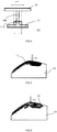
figure 1 qui représente une situation involontaire, un glissement relatif entre la glace 2 et le socle 1 au niveau de leurs cordons de soudure 4, 3 respectifs est susceptible d'apparaitre fortuitement, rompant la situation de parallélisme du socle 1 par rapport à la glace 2. Il en résulte un risque de casse de la glace 2 et/ou du socle 1, un risque d'une mauvaise soudure, voire fragile. Il peut même arriver de manière insatisfaisante que le socle 1 soit fixé à la glace 2 dans une position ne correspondant pas du tout à la position attendue, présentant un décalage repéré D ou une absence de parallélisme, impliquant un risque de mise au rebus pour non-conformité du dispositif lumineux. -
JP 2000 025116 - Bien que les problèmes présentés ci-dessus concernent particulièrement le domaine technique concerné par le couple constitué de la glace et du socle associé d'un dispositif lumineux, ces problèmes sont susceptibles d'apparaitre pour d'autres couples de pièces d'un dispositif lumineux pour véhicule automobile.
- Le but de la présente invention est de proposer une solution d'assemblage par soudure miroir de deux pièces entre elles d'un dispositif lumineux pour véhicule automobile qui remédie aux inconvénients listés ci-dessus.
- A cet égard, l'invention a pour objet un procédé d'assemblage entre elles par soudure miroir d'une première pièce et d'une deuxième pièce d'un dispositif lumineux pour véhicule automobile, comprenant une étape de fourniture des première et deuxième pièces où chaque pièce comprend, dans sa zone d'interface de contact avec l'autre pièce, un cordon de soudure destiné à venir en contact contre le cordon de soudure de l'autre pièce durant la soudure miroir.
- Ce procédé est remarquable en ce que le cordon de soudure d'au moins l'une desdites première et deuxième pièces est muni d'une pluralité de nervures élargisseurs échelonnées le long de la longueur dudit cordon de soudure, chaque nervure élargisseur étant configurée de manière à élargir localement la largeur du cordon de soudure par rapport à la largeur du cordon de soudure en dehors des zones où les nervures élargisseurs sont présentes.
- Selon un mode de réalisation avantageux, pour le cordon de soudure qui en est équipé, des nervures élargisseurs sont disposées de part et d'autre du cordon de soudure par rapport à sa direction d'extension.
- En particulier, deux nervures élargisseurs sont agencées localement perpendiculairement ou en épi par rapport à la direction d'extension du cordon de soudure, dans l'alignement l'une de l'autre, de sorte à constituer un croisillon conjointement avec ledit cordon de soudure. Selon une variante de réalisation, deux nervures élargisseurs respectivement s'étendant d'un côté et de l'autre du cordon de soudure sont décalées entre elles le long de la longueur du cordon de soudure selon une organisation en quinconce.
- Selon un mode de réalisation avantageux, chaque nervure élargisseur s'étend sur une longueur comprise entre 1,5 mm et 4 mm depuis le cordon de soudure.
- Selon un mode de réalisation avantageux, la hauteur de chaque nervure élargisseur est supérieure ou égale à la hauteur du cordon de soudure, comptées depuis la face de la pièce à partir de laquelle la nervure élargisseur prend naissance.
- En particulier et avantageusement, chaque nervure élargisseur est conformée de sorte que sa hauteur tend à augmenter en s'éloignant du cordon de soudure.
- Selon un mode de réalisation du procédé, après l'étape de fourniture, ledit procédé comprend une première étape de mise en contact des première et deuxième pièces au niveau de leurs cordons de soudure, dans laquelle les nervures élargisseurs de chaque pièce qui en est équipée participent au positionnement du cordon de soudure de l'autre pièce et à la conformation spatiale de ladite autre pièce, puis une étape de soudure miroir des première pièce et deuxième pièce entre elles au niveau de leurs cordons de soudure et des nervures élargisseurs.
- En particulier, durant la première étape de mise en contact, la pièce dont le cordon de soudure comprend les nervures élargisseurs est supportée par un outil inférieur et en ce que l'étape de soudure miroir comprend une étape de préhension de la pièce pré-centrée durant la première étape de mise en contact par un outil supérieur, le centrage et la conformation spatiale de ladite autre pièce étant obtenus par les nervures élargisseurs de la pièce dont le cordon de soudure en est équipé durant l'étape de préhension.
- Selon une autre caractéristique particulière, la première étape de mise en contact comprend une étape de mise en place manuelle de ladite autre pièce sur la pièce dont le cordon de soudure est équipé de nervures élargisseurs.
- Selon un mode de réalisation avantageux, l'étape de soudure miroir comprend, suite à l'étape de préhension, une étape de déplacement relatif entre les outils supérieur et inférieur de sorte à éloigner les première et deuxième pièces l'une de l'autre, une étape de ramollissement au moins partiel de chaque cordon de soudure des première et deuxième pièces par un miroir chauffant, puis une deuxième étape de mise en contact par pression des première et deuxième pièces au niveau de leurs cordons de soudure encore au moins partiellement ramollis.
- Selon une caractéristique avantageuse, les première et deuxième pièces sont configurées pour former après la soudure miroir, un dispositif lumineux de type dispositif de signalisation de véhicule automobile, par exemple un feu de signalisation arrière, l'une des première et deuxième pièces, notamment la pièce dont le cordon de soudure est équipée des nervures élargisseurs, étant constituée par un socle, et l'autre des première et deuxième pièces étant constituée par une glace au moins partiellement transparente à la lumière.
- D'autres avantages et caractéristiques ressortiront plus clairement de la description qui va suivre de modes particuliers de réalisation de l'invention donnés à titre d'exemples non limitatifs et représentés sur les dessins annexés, dans lesquels :
- la
figure 1 déjà décrite est une vue schématique, en coupe longitudinale, des problèmes risquant de subvenir avec les techniques d'assemblage actuelles, - les
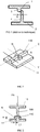
figures 2 et 3 sont des vues respectivement en perspective et en coupe d'un exemple de pièce utilisée dans un exemple de procédé d'assemblage selon l'invention, - la
figure 4 illustre le glissement E1 des pièces qui peut être compensé grâce au procédé selon l'invention, - les
figures 5 à 8 représentent quatre étapes successives de mise en oeuvre de l'exemple de procédé d'assemblage selon l'invention. - L'invention qui va maintenant être décrite en référence aux
figures 2 à 8 annexées concerne globalement un procédé d'assemblage entre elles, par une technique de soudure miroir, d'une première pièce et d'une deuxième pièce 10, 11 appartenant à un dispositif lumineux pour véhicule automobile. - Le procédé comprend une étape de fourniture des première et deuxième pièces 10, 11 où chaque pièce 10, 11 comprend, dans sa zone d'interface de contact avec l'autre pièce, un cordon de soudure, respectivement 100, 110, destiné à venir en contact contre le cordon de soudure de l'autre pièce durant la soudure miroir.
- L'opération de soudure miroir est aussi connue sous le nom de soudure par lame chauffante. Cette technique consiste à positionner les deux pièces 10, 11, qui sont préférentiellement formées dans une matière plastique idoine au moins dans la zone des cordons de soudure 100, 110, l'une au-dessus de l'autre en laissant un espace entre celles-ci, par exemple d'environ 50 cm. Ensuite, un miroir, par exemple une lame chauffante, qui chauffe sur deux côtés opposés est introduit dans cet espace. Les deux pièces 10, 11 viennent ensuite en contact avec le miroir ou sont placées à proximité de celui-ci (miroir avec infrarouge ou gaz chaud) au niveau des cordons de soudure 100, 110 jusqu'à ce que la température de la matière de chaque pièce 10, 11, au niveau du cordon de soudure 100, 110, ait atteint sa température de ramollissement en surface. Lorsque les températures de ramollissement sont atteintes, il suffit de retirer le miroir chauffant et de mettre en contact sous pression les deux pièces 10, 11 l'une avec l'autre au niveau de leurs cordons de soudure 100, 110 encore à l'état ramolli pendant quelques secondes. Après quelques secondes de refroidissement sous pression, la soudure est réalisée : les deux pièces 10, 11 sont liées l'une à l'autre au niveau de leurs cordons de soudure 100, 110, eux-mêmes solidarisés l'un à l'autre après leur refroidissement.
- Selon une caractéristique importante, le cordon de soudure 110 d'au moins l'une des première et deuxième pièces 10, 11 (par exemple uniquement le cordon de soudure 110 de la deuxième pièce 11) est muni d'une pluralité de nervures élargisseurs N échelonnées le long de la longueur (comptée suivant sa longueur d'extension X suivant laquelle il s'étend) dudit cordon de soudure 110. Chaque nervure élargisseur N est configurée de manière à élargir localement la largeur du cordon de soudure 110 par rapport à la largeur L du cordon de soudure 110 en dehors des zones où les nervures élargisseurs N sont présentes (voir l'illustration sur la
figure 2 par exemple). - Le dispositif lumineux obtenu par l'assemblage des pièces 10, 11 peut indifféremment être de type dispositif de signalisation de véhicule automobile, par exemple un feu de signalisation arrière, ou encore de type dispositif d'éclairage extérieur du véhicule automobile ou de type dispositif d'éclairage intérieur du véhicule automobile. Notamment mais non exclusivement, les première et deuxième pièces 10, 11 sont configurées pour former après la soudure miroir, un dispositif lumineux de type dispositif de signalisation de véhicule automobile, par exemple un feu de signalisation arrière, l'une 11 des première et deuxième pièces 10, 11, notamment la pièce 11 dont le cordon de soudure 110 est équipée des nervures élargisseurs N, étant constituée par un socle du dispositif de signalisation, et l'autre 10 des première et deuxième pièces 10, 11 étant constituée par une glace du dispositif de signalisation, au moins partiellement transparente à la lumière.
- Dans la suite, il sera pris l'exemple avantageux où la pièce munie de nervures élargisseurs N est la deuxième pièce 11 et le cordon de soudure concerné est le cordon de soudure repéré 110. Toutefois, alternativement ou en combinaison, la pièce munie de nervures élargisseurs N peut être la première pièce 10 et le cordon de soudure concerné est dans ce cas le cordon de soudure repéré 100. Ainsi, les deux cordons de soudure 100, 110 des deux pièces 10, 11 peuvent simultanément être équipés de nervures élargisseurs, ou bien il peut être prévu qu'un seul des deux cordons de soudure 100, 110 soit équipé de telles nervures élargisseurs N.
- Selon un mode de réalisation tel qu'illustré, pour le cordon de soudure 110 qui en est équipé, des nervures élargisseurs N sont disposées de part et d'autre du cordon de soudure 110 par rapport à sa direction d'extension X, ce qui correspond à la direction latérale repérée Y. Il reste toutefois envisageable que les nervures élargisseurs N qui équipent un même cordon de soudure soient toutes agencées d'un même côté du cordon de soudure vu dans la direction Y.
- Deux nervures élargisseurs N sont agencées localement perpendiculairement (ce qui est le cas représenté) ou en épi (situation non représentée) par rapport à la direction d'extension X du cordon de soudure 110, dans l'alignement l'une de l'autre, de sorte à constituer un croisillon (
figure 2 ) conjointement avec le cordon de soudure 110 équipé de ces nervures N. - Toutefois, dans une variante non représentée, deux nervures élargisseurs N respectivement s'étendant d'un côté et de l'autre du cordon de soudure 110 suivant la direction Y, sont décalées entre elles le long de la longueur (c'est-à-dire suivant la direction d'extension X) du cordon de soudure 110 selon une organisation en quinconce.
- Un dimensionnement possible qui donne une entière satisfaction pour la fonction recherchée, notamment dans le cas d'une première pièce 10 constituée d'une glace et d'une deuxième pièce 11 constituée d'un socle d'un même dispositif de signalisation, prévoit que chaque nervure élargisseur N s'étend sur une longueur L1 (visible sur la
figure 3 ) comprise entre 1,5 mm et 4 mm, préférentiellement entre 1,5 et 2,5 mm, depuis le cordon de soudure 110 d'où elle prend naissance. - Selon un mode préféré, la hauteur H (visible sur la
figure 3 ) de chaque nervure élargisseur N est supérieure ou égale à la hauteur du cordon de soudure 110, ces deux hauteurs étant comptées depuis la face de la pièce 11 à partir de laquelle la nervure élargisseur N prend naissance. - De manière non illustrée, il peut notamment être prévu que chaque nervure élargisseur N soit conformée de sorte que sa hauteur H tende à augmenter en s'éloignant du cordon de soudure 110, permettant de créer une forme d'entonnoir local qui peut participer au centrage (pour mise en place et un maintien du positionnement de l'autre cordon de soudure 100). Toutefois, de la manière illustrée, il est tout à fait envisageable que la hauteur de la nervure élargisseur N soit constante sur sa longueur.
- Après l'étape de fourniture des pièces 10, 11, le procédé d'assemblage comprend :
- une première étape de mise en contact F1, F2 (
figures 5, 6 ) des première et deuxième pièces 10, 11 au niveau de leurs cordons de soudure 100, 110, dans laquelle les nervures élargisseurs N de chaque pièce qui en est équipée (ici constituée par la deuxième pièce 11) participent au positionnement du cordon de soudure 100 de l'autre pièce (ici constituée par la première pièce 10) et à la conformation spatiale de ladite autre pièce 10, - puis une étape de soudure miroir de la première pièce 10 et la deuxième pièce 11 entre elles au niveau de leurs cordons de soudure 100, 110 et des nervures élargisseurs N.
- Durant la première étape de mise en contact F1, F2, la pièce 11 dont le cordon de soudure 110 comprend les nervures élargisseurs N est de préférence supportée par un outil inférieur OI (
figure 5 ). L'étape de soudure miroir comprend ensuite une étape de préhension F3 (figure 7 ) de la pièce 10 pré-centrée durant la première étape de mise en contact F1, F2 par un outil supérieur OS. Le centrage et la conformation spatiale de ladite autre pièce (ici constituée par la première pièce 10) sont très avantageusement maintenus durant l'étape de préhension F3 et grandement facilités par les nervures élargisseurs N de la pièce dont le cordon de soudure 110 en est équipé (ici constituée par la deuxième pièce 11) et sur laquelle elle repose. - Autrement dit, le simple contact de la pièce 10 au niveau de son cordon de soudure 100 contre le cordon de soudure 110 et les nervures élargisseurs N de la pièce 11 qui repose sur l'outil inférieur OI suffit, au moment de la préhension F3 de la pièce 10 par l'outil supérieur OS qui s'accompagne de l'application d'un effort F5 (
figure 2 ) de l'outil supérieur OS sur la pièce 10, à garantir le positionnement et la conformation spatiale de la pièce 10. Ces dispositions sont très avantageuses par rapport à l'art antérieur précédemment présenté. - Selon un mode de réalisation particulier, la première étape de mise en contact F1, F2 comprend une étape de mise en place manuelle de ladite autre pièce (ici constituée par la première pièce 10) sur la pièce (ici constituée par la deuxième pièce 11) dont le cordon de soudure 110 est équipé de nervures élargisseurs N.
- Ensuite, l'étape de soudure miroir comprend, suite à l'étape de préhension F3, une étape de déplacement relatif F4 entre les outils supérieur et inférieur OS, OI de sorte à éloigner les première et deuxième pièces 10, 11 l'une de l'autre, une étape de ramollissement au moins partiel ou de fusion au moins partielle de chaque cordon de soudure 100, 110 des première et deuxième pièces 10, 11 par un miroir chauffant, puis une deuxième étape de mise en contact sous pression des première et deuxième pièces 10, 11 au niveau de leurs cordons de soudure 100, 110 encore au moins partiellement ramollis.
- Durant l'étape de déplacement relatif, la deuxième pièce 11 dont le cordon de soudure 110 est équipé des nervures élargisseurs N reste solidaire de l'outil inférieur OI tandis que l'autre pièce, ici la première pièce 10 qui est par exemple dépourvue de nervure élargisseur N bien qu'elle pourrait indifféremment en comprendre en complément ou en substitution de celles de la deuxième pièce 11, reste solidaire de l'outil supérieur OS après sa préhension F3 par ce dernier. Le déplacement relatif F4 est par exemple obtenu par un déplacement vers le haut de l'outil supérieur OS alors que l'outil inférieur OI reste fixe. A l'inverse, le déplacement relatif F4 pourrait être obtenu par un déplacement vers le bas de l'outil inférieur OI alors que l'outil supérieur OS resterait fixe. Ces déplacements des outils OI et OS pourraient aussi être combinés.
- En résumé, la pièce 11 est d'abord déposée manuellement sur l'outil inférieur OI (flèche F1), puis l'autre pièce 10 est mise en place manuellement sur la pièce 11 (flèche F2) afin de créer une première mise en contact entre les pièces 10, 11, puis la pièce 10 est saisie par l'outil supérieur OS (flèche F3) durant l'étape de préhension, puis la pièce 10 ainsi saisie est déplacée par rapport à la pièce 11 par l'intermédiaire d'au moins l'un des outils OI et OS, puis l'étape de soudure miroir est finalisée moyennant une deuxième mise en contact sous pression des pièces 10, 11 à un moment où les cordons de soudure 110, 100 sont encore à l'état ramolli après chauffage par le miroir ou la lame chauffante.
- Les nervures élargisseurs N ajoutées localement dans la largeur du cordon de soudure 110 permettent un pré-positionnement manuel aisé des pièces 10, 11 par l'opérateur. Elles permettent aussi d'accepter les dispersions de fabrication des pièces 10, 11. Les nervures élargisseurs permettent aux deux pièces 10, 11 de glisser l'une par rapport a l'autre, et ainsi de centrer et de conformer la pièce 10 par le biais du procédé de soudure miroir lui-même afin d'assurer un bon positionnement des pièces 10, 11 lors de leur assemblage. La
figure 5 schématise la tolérance de glissement E1 des pièces 10, 11 l'une par rapport à l'autre, dans laquelle la pièce 10 est malgré tout maintenue en position de centrage et conformée spatialement via les nervures élargisseurs N de la pièce 11. Cette valeur de E1 est directement liée à la largeur totale E2 du cordon de soudure 110 au niveau des nervures élargisseurs N qui l'équipent et à la largeur du cordon de soudure 100. - Un autre avantage des nervures élargisseurs N est une amélioration de l'ergonomie du poste de travail au sein duquel le procédé d'assemblage est réalisé. Cela permet de charger manuellement la pièce 11, même si elle a un poids élevé, en partie inférieure de la machine (plus précisément sur l'outil inférieur OI) et de positionner la pièce 10 sur cette pièce 11 précédemment chargée. Contrairement à l'art antérieur, il n'y a pas d'effort à exercer pour conformer la pièce 10 et pour fixer la pièce 10 qui est potentiellement lourde au-dessus des épaules de l'opérateur.
- Enfin, il s'agit d'une solution adaptable et simple à mettre en place sur divers produits, répétable sur la pièce 11 et/ou la pièce 10.
- On comprend bien de la description qui précède que le procédé selon l'invention est particulièrement bien adapté pour la réalisation de feux de signalisation de véhicules, notamment automobiles.
Claims (12)
- Procédé d'assemblage entre elles par soudure miroir d'une première pièce (10) et d'une deuxième pièce (11) d'un dispositif lumineux pour véhicule automobile, comprenant une étape de fourniture des première et deuxième pièces (10, 11) où chaque pièce (10, 11) comprend, dans sa zone d'interface de contact avec l'autre pièce, un cordon de soudure (100, 110) destiné à venir en contact contre le cordon de soudure de l'autre pièce durant la soudure miroir, caractérisé en ce que le cordon de soudure (110) d'au moins l'une (11) desdites première et deuxième pièces (10, 11) est muni d'une pluralité de nervures élargisseurs (N) échelonnées le long de la longueur dudit cordon de soudure (110), chaque nervure élargisseur (N) étant configurée de manière à élargir localement la largeur du cordon de soudure (110) par rapport à la largeur (L) du cordon de soudure (110) en dehors des zones où les nervures élargisseurs (N) sont présentes.
- Procédé d'assemblage selon la revendication 1, caractérisé en ce que pour le cordon de soudure (110) qui en est équipé, des nervures élargisseurs (N) sont disposées de part et d'autre du cordon de soudure (110) par rapport à sa direction d'extension (X).
- Procédé d'assemblage selon la revendication 2, caractérisé en ce que deux nervures élargisseurs (N) sont agencées localement perpendiculairement ou en épi par rapport à la direction d'extension (X) du cordon de soudure (110), dans l'alignement l'une de l'autre, de sorte à constituer un croisillon conjointement avec ledit cordon de soudure (110).
- Procédé d'assemblage selon l'une des revendications 2 ou 3, caractérisé en ce que deux nervures élargisseurs (N) respectivement s'étendant d'un côté et de l'autre du cordon de soudure (110) sont décalées entre elles le long de la longueur du cordon de soudure (110) selon une organisation en quinconce.
- Procédé d'assemblage selon l'une des revendications 1 à 4, caractérisé en ce que chaque nervure élargisseur (N) s'étend sur une longueur (L1) comprise entre 1,5 mm et 4 mm depuis le cordon de soudure (110).
- Procédé d'assemblage selon l'une des revendications 1 à 5, caractérisé en ce que la hauteur (H) de chaque nervure élargisseur (N) est supérieure ou égale à la hauteur du cordon de soudure (110), comptées depuis la face de la pièce (11) à partir de laquelle la nervure élargisseur (N) prend naissance.
- Procédé d'assemblage selon la revendication 6, caractérisé en ce que chaque nervure élargisseur (N) est conformée de sorte que sa hauteur (H) tend à augmenter en s'éloignant du cordon de soudure (110).
- Procédé d'assemblage selon l'une des revendications 1 à 7, caractérisé en ce qu'après l'étape de fourniture, il comprend une première étape de mise en contact (F1, F2) des première et deuxième pièces (10, 11) au niveau de leurs cordons de soudure (100, 110), dans laquelle les nervures élargisseurs (N) de chaque pièce (11) qui en est équipée participent au positionnement du cordon de soudure (100) de l'autre pièce (10) et à la conformation spatiale de ladite autre pièce (10), puis une étape de soudure miroir des première pièce (10) et deuxième pièce (11) entre elles au niveau de leurs cordons de soudure (100, 110) et des nervures élargisseurs (N).
- Procédé d'assemblage selon la revendication 8, caractérisé en ce que durant la première étape de mise en contact (F1, F2), la pièce (11) dont le cordon de soudure (110) comprend les nervures élargisseurs (N) est supportée par un outil inférieur (OI) et en ce que l'étape de soudure miroir comprend une étape de préhension (F3) de la pièce (10) pré-centrée durant la première étape de mise en contact (F1, F2) par un outil supérieur (OS), le centrage et la conformation spatiale de ladite autre pièce (10) étant obtenus par les nervures élargisseurs (N) de la pièce (11) dont le cordon de soudure (110) en est équipé durant l'étape de préhension (F3).
- Procédé d'assemblage selon l'une des revendications 8 ou 9, caractérisé en ce que la première étape de mise en contact (F1, F2) comprend une étape de mise en place manuelle (F2) de ladite autre pièce (10) sur la pièce (11) dont le cordon de soudure (110) est équipé de nervures élargisseurs (N).
- Procédé d'assemblage selon l'une des revendications 9 ou 10, caractérisé en ce que l'étape de soudure miroir comprend, suite à l'étape de préhension (F3), une étape de déplacement relatif (F4) entre les outils supérieur et inférieur (OS, OI) de sorte à éloigner les première et deuxième pièces (10, 11) l'une de l'autre, une étape de ramollissement au moins partiel de chaque cordon de soudure (100, 110) des première et deuxième pièces (10, 11) par un miroir chauffant, puis une deuxième étape de mise en contact par pression des première et deuxième pièces (10, 11) au niveau de leurs cordons de soudure (100, 110) encore au moins partiellement ramollis.
- Procédé d'assemblage selon l'une des revendications 1 à 11, caractérisé en ce que les première et deuxième pièces (10, 11) sont configurées pour former après la soudure miroir, un dispositif lumineux de type dispositif de signalisation de véhicule automobile, par exemple un feu de signalisation arrière, l'une (11) des première et deuxième pièces (10, 11), notamment la pièce dont le cordon de soudure (110) est équipée des nervures élargisseurs (N), étant constituée par un socle, et l'autre (10) des première et deuxième pièces (10, 11) étant constituée par une glace au moins partiellement transparente à la lumière.
Applications Claiming Priority (2)
| Application Number | Priority Date | Filing Date | Title |
|---|---|---|---|
| FR1459272A FR3026343B1 (fr) | 2014-09-30 | 2014-09-30 | Assemblage de deux pieces d'un dispositif lumineux par soudure miroir via des nervures elargisseurs |
| PCT/EP2015/072168 WO2016050652A1 (fr) | 2014-09-30 | 2015-09-25 | Assemblage de deux pièces d'un dispositif lumineux par soudure miroir via des nervures élargisseurs |
Publications (2)
| Publication Number | Publication Date |
|---|---|
| EP3200971A1 EP3200971A1 (fr) | 2017-08-09 |
| EP3200971B1 true EP3200971B1 (fr) | 2018-10-10 |
Family
ID=51842660
Family Applications (1)
| Application Number | Title | Priority Date | Filing Date |
|---|---|---|---|
| EP15770880.1A Active EP3200971B1 (fr) | 2014-09-30 | 2015-09-25 | Assemblage de deux pièces d'un dispositif lumineux par soudure miroir via des nervures élargisseurs |
Country Status (5)
| Country | Link |
|---|---|
| US (1) | US10486366B2 (fr) |
| EP (1) | EP3200971B1 (fr) |
| CN (1) | CN107073828B (fr) |
| FR (1) | FR3026343B1 (fr) |
| WO (1) | WO2016050652A1 (fr) |
Families Citing this family (1)
| Publication number | Priority date | Publication date | Assignee | Title |
|---|---|---|---|---|
| CN112976591B (zh) * | 2021-02-18 | 2022-11-22 | 烟台佳合塑胶科技有限公司 | 一种高刚性塑料制品加工工艺 |
Family Cites Families (10)
| Publication number | Priority date | Publication date | Assignee | Title |
|---|---|---|---|---|
| JP3328166B2 (ja) * | 1997-06-12 | 2002-09-24 | 株式会社小糸製作所 | 車両用灯具の振動溶着方法及びその振動溶着装置 |
| JP2000025116A (ja) * | 1998-07-10 | 2000-01-25 | Takagi Seiko Corp | 熱板溶着方法とそれに要する受治具 |
| JP4021120B2 (ja) * | 2000-04-13 | 2007-12-12 | 株式会社小糸製作所 | 車両用灯具の製造装置 |
| JP3913459B2 (ja) * | 2000-11-13 | 2007-05-09 | 株式会社小糸製作所 | 車両用灯具の製造方法 |
| JP2004345094A (ja) * | 2003-05-20 | 2004-12-09 | Koito Mfg Co Ltd | 車両用灯具の製造装置 |
| JP4566613B2 (ja) * | 2004-04-28 | 2010-10-20 | キヤノン株式会社 | レンズ固定方法 |
| JP4757226B2 (ja) * | 2007-05-16 | 2011-08-24 | カルソニックカンセイ株式会社 | 振動溶着部構造 |
| DE102010017796A1 (de) * | 2009-07-30 | 2011-02-17 | Kobayashi Industrial Co., Ltd., Fujinomiya | Harzbauteil-Schweissvorrichtung und Verfahren zum Verschweissen von Harzbauteilen |
| US20130157015A1 (en) * | 2011-12-20 | 2013-06-20 | GM Global Technology Operations LLC | Precisely Locating Components in an Infrared Welded Assembly |
| JP2014063653A (ja) * | 2012-09-21 | 2014-04-10 | Isuzu Motors Ltd | ランプの製造方法 |
-
2014
- 2014-09-30 FR FR1459272A patent/FR3026343B1/fr active Active
-
2015
- 2015-09-25 WO PCT/EP2015/072168 patent/WO2016050652A1/fr not_active Ceased
- 2015-09-25 US US15/515,921 patent/US10486366B2/en active Active
- 2015-09-25 EP EP15770880.1A patent/EP3200971B1/fr active Active
- 2015-09-25 CN CN201580053149.9A patent/CN107073828B/zh active Active
Non-Patent Citations (1)
| Title |
|---|
| None * |
Also Published As
| Publication number | Publication date |
|---|---|
| FR3026343B1 (fr) | 2016-10-28 |
| EP3200971A1 (fr) | 2017-08-09 |
| CN107073828A (zh) | 2017-08-18 |
| CN107073828B (zh) | 2019-04-26 |
| US10486366B2 (en) | 2019-11-26 |
| FR3026343A1 (fr) | 2016-04-01 |
| WO2016050652A1 (fr) | 2016-04-07 |
| US20170305072A1 (en) | 2017-10-26 |
Similar Documents
| Publication | Publication Date | Title |
|---|---|---|
| EP2195135B1 (fr) | Procede de soudage de pieces par friction malaxage utilisant un dispositif a double epaulement | |
| FR2785043A1 (fr) | Condenseur brase destine a un systeme de climatisation | |
| EP2566683B1 (fr) | Dispositif d'assemblage de deux pieces en materiaux thermoplastiques par soudage laser par transparence et procede d'assemblage associe | |
| FR2694514A1 (fr) | Procédé de soudage bord à bord d'au moins deux tôles. | |
| EP2111333B1 (fr) | Procede de solidarisation de premiere et seconde pieces en matiere thermoplastique | |
| EP3200971B1 (fr) | Assemblage de deux pièces d'un dispositif lumineux par soudure miroir via des nervures élargisseurs | |
| EP2408585B1 (fr) | Dispositif de soudobrasage | |
| WO2014097043A1 (fr) | Procédé et moule pour le soudage des extrémités de deux portions de rail | |
| EP1854707A1 (fr) | Elément de liaison pour réaliser un longeron pour véhicule automobile et longeron comportant un tel élément | |
| FR2709083A1 (fr) | Flan de tôle de structure multicouche à soudabilité et à emboutissabilité améliorée et procédé et dispositif de fabrication de ce type de flans de tôle. | |
| FR2713740A1 (fr) | Procédé de fixation d'une bague d'arrêt à un embout mâle d'un tuyau. | |
| FR3094245A1 (fr) | Procédé et outillage pour la mise en forme d’une arête sur un embouti | |
| EP3130412B1 (fr) | Outillage d'emboutissage avec guidage sans serrage | |
| FR2983768A1 (fr) | Embout de bridage equipe d'un accessoire de bridage pour un dispositif d'assemblage deux pieces par soudage laser par transparence et procede de remplacement d'un tel accessoire | |
| EP1164346A1 (fr) | Manchon permettant de relier de facon étanche deux parois planes espacées parallèles en tôle de relativement faible épaisseur | |
| FR3040907A1 (fr) | Profile soudable et procede associe, pour la soudure de panneaux en materiau plastique | |
| FR3141359A1 (fr) | Procédé de soudage par friction malaxage et ensemble de soudage associé | |
| EP1935615A1 (fr) | Procédé de solidarisation de première et seconde pièces en matière thermoplastique | |
| FR3059590A1 (fr) | Installation et procede de soudage par vibration | |
| EP3144126A1 (fr) | Profile soudable et procédé associé, pour la soudure de panneaux en matériau plastique | |
| FR3003491A1 (fr) | Soudage de feuillures aluminium par bossage. | |
| FR2793433A1 (fr) | Procede d'assemblage par soudage d'un element creux en aluminium de carrosserie automobile, et element creux assemble selon le procede | |
| FR3046738A1 (fr) | Procede et dispositif d'assemblage par soudage laser par transparence d'une premiere piece comprenant au moins un element de liaison avec une deuxieme piece | |
| FR2737143A1 (fr) | Procede et dispositif pour decouper au moyen d'une presse la paroi peripherique tubulaire d'un organe en forme de bol | |
| FR2958571A1 (fr) | Procede d'assemblage de deux pieces en tole par soudo-brasage. |
Legal Events
| Date | Code | Title | Description |
|---|---|---|---|
| STAA | Information on the status of an ep patent application or granted ep patent |
Free format text: STATUS: THE INTERNATIONAL PUBLICATION HAS BEEN MADE |
|
| PUAI | Public reference made under article 153(3) epc to a published international application that has entered the european phase |
Free format text: ORIGINAL CODE: 0009012 |
|
| STAA | Information on the status of an ep patent application or granted ep patent |
Free format text: STATUS: REQUEST FOR EXAMINATION WAS MADE |
|
| 17P | Request for examination filed |
Effective date: 20170328 |
|
| AK | Designated contracting states |
Kind code of ref document: A1 Designated state(s): AL AT BE BG CH CY CZ DE DK EE ES FI FR GB GR HR HU IE IS IT LI LT LU LV MC MK MT NL NO PL PT RO RS SE SI SK SM TR |
|
| AX | Request for extension of the european patent |
Extension state: BA ME |
|
| DAV | Request for validation of the european patent (deleted) | ||
| DAX | Request for extension of the european patent (deleted) | ||
| GRAP | Despatch of communication of intention to grant a patent |
Free format text: ORIGINAL CODE: EPIDOSNIGR1 |
|
| STAA | Information on the status of an ep patent application or granted ep patent |
Free format text: STATUS: GRANT OF PATENT IS INTENDED |
|
| RIC1 | Information provided on ipc code assigned before grant |
Ipc: F21S 43/20 20180101ALI20180412BHEP Ipc: B29C 65/78 20060101ALI20180412BHEP Ipc: F21S 43/27 20180101ALI20180412BHEP Ipc: B29C 65/20 20060101AFI20180412BHEP |
|
| INTG | Intention to grant announced |
Effective date: 20180516 |
|
| GRAS | Grant fee paid |
Free format text: ORIGINAL CODE: EPIDOSNIGR3 |
|
| GRAA | (expected) grant |
Free format text: ORIGINAL CODE: 0009210 |
|
| STAA | Information on the status of an ep patent application or granted ep patent |
Free format text: STATUS: THE PATENT HAS BEEN GRANTED |
|
| AK | Designated contracting states |
Kind code of ref document: B1 Designated state(s): AL AT BE BG CH CY CZ DE DK EE ES FI FR GB GR HR HU IE IS IT LI LT LU LV MC MK MT NL NO PL PT RO RS SE SI SK SM TR |
|
| REG | Reference to a national code |
Ref country code: GB Ref legal event code: FG4D Free format text: NOT ENGLISH |
|
| REG | Reference to a national code |
Ref country code: AT Ref legal event code: REF Ref document number: 1050714 Country of ref document: AT Kind code of ref document: T Effective date: 20181015 Ref country code: CH Ref legal event code: EP |
|
| REG | Reference to a national code |
Ref country code: IE Ref legal event code: FG4D Free format text: LANGUAGE OF EP DOCUMENT: FRENCH |
|
| REG | Reference to a national code |
Ref country code: DE Ref legal event code: R096 Ref document number: 602015017970 Country of ref document: DE |
|
| REG | Reference to a national code |
Ref country code: NL Ref legal event code: FP |
|
| REG | Reference to a national code |
Ref country code: LT Ref legal event code: MG4D |
|
| REG | Reference to a national code |
Ref country code: AT Ref legal event code: MK05 Ref document number: 1050714 Country of ref document: AT Kind code of ref document: T Effective date: 20181010 |
|
| PG25 | Lapsed in a contracting state [announced via postgrant information from national office to epo] |
Ref country code: HR Free format text: LAPSE BECAUSE OF FAILURE TO SUBMIT A TRANSLATION OF THE DESCRIPTION OR TO PAY THE FEE WITHIN THE PRESCRIBED TIME-LIMIT Effective date: 20181010 Ref country code: BG Free format text: LAPSE BECAUSE OF FAILURE TO SUBMIT A TRANSLATION OF THE DESCRIPTION OR TO PAY THE FEE WITHIN THE PRESCRIBED TIME-LIMIT Effective date: 20190110 Ref country code: FI Free format text: LAPSE BECAUSE OF FAILURE TO SUBMIT A TRANSLATION OF THE DESCRIPTION OR TO PAY THE FEE WITHIN THE PRESCRIBED TIME-LIMIT Effective date: 20181010 Ref country code: IS Free format text: LAPSE BECAUSE OF FAILURE TO SUBMIT A TRANSLATION OF THE DESCRIPTION OR TO PAY THE FEE WITHIN THE PRESCRIBED TIME-LIMIT Effective date: 20190210 Ref country code: LT Free format text: LAPSE BECAUSE OF FAILURE TO SUBMIT A TRANSLATION OF THE DESCRIPTION OR TO PAY THE FEE WITHIN THE PRESCRIBED TIME-LIMIT Effective date: 20181010 Ref country code: NO Free format text: LAPSE BECAUSE OF FAILURE TO SUBMIT A TRANSLATION OF THE DESCRIPTION OR TO PAY THE FEE WITHIN THE PRESCRIBED TIME-LIMIT Effective date: 20190110 Ref country code: PL Free format text: LAPSE BECAUSE OF FAILURE TO SUBMIT A TRANSLATION OF THE DESCRIPTION OR TO PAY THE FEE WITHIN THE PRESCRIBED TIME-LIMIT Effective date: 20181010 Ref country code: ES Free format text: LAPSE BECAUSE OF FAILURE TO SUBMIT A TRANSLATION OF THE DESCRIPTION OR TO PAY THE FEE WITHIN THE PRESCRIBED TIME-LIMIT Effective date: 20181010 Ref country code: AT Free format text: LAPSE BECAUSE OF FAILURE TO SUBMIT A TRANSLATION OF THE DESCRIPTION OR TO PAY THE FEE WITHIN THE PRESCRIBED TIME-LIMIT Effective date: 20181010 Ref country code: LV Free format text: LAPSE BECAUSE OF FAILURE TO SUBMIT A TRANSLATION OF THE DESCRIPTION OR TO PAY THE FEE WITHIN THE PRESCRIBED TIME-LIMIT Effective date: 20181010 |
|
| PG25 | Lapsed in a contracting state [announced via postgrant information from national office to epo] |
Ref country code: PT Free format text: LAPSE BECAUSE OF FAILURE TO SUBMIT A TRANSLATION OF THE DESCRIPTION OR TO PAY THE FEE WITHIN THE PRESCRIBED TIME-LIMIT Effective date: 20190210 Ref country code: SE Free format text: LAPSE BECAUSE OF FAILURE TO SUBMIT A TRANSLATION OF THE DESCRIPTION OR TO PAY THE FEE WITHIN THE PRESCRIBED TIME-LIMIT Effective date: 20181010 Ref country code: AL Free format text: LAPSE BECAUSE OF FAILURE TO SUBMIT A TRANSLATION OF THE DESCRIPTION OR TO PAY THE FEE WITHIN THE PRESCRIBED TIME-LIMIT Effective date: 20181010 Ref country code: RS Free format text: LAPSE BECAUSE OF FAILURE TO SUBMIT A TRANSLATION OF THE DESCRIPTION OR TO PAY THE FEE WITHIN THE PRESCRIBED TIME-LIMIT Effective date: 20181010 Ref country code: GR Free format text: LAPSE BECAUSE OF FAILURE TO SUBMIT A TRANSLATION OF THE DESCRIPTION OR TO PAY THE FEE WITHIN THE PRESCRIBED TIME-LIMIT Effective date: 20190111 |
|
| REG | Reference to a national code |
Ref country code: DE Ref legal event code: R097 Ref document number: 602015017970 Country of ref document: DE |
|
| PG25 | Lapsed in a contracting state [announced via postgrant information from national office to epo] |
Ref country code: CZ Free format text: LAPSE BECAUSE OF FAILURE TO SUBMIT A TRANSLATION OF THE DESCRIPTION OR TO PAY THE FEE WITHIN THE PRESCRIBED TIME-LIMIT Effective date: 20181010 Ref country code: IT Free format text: LAPSE BECAUSE OF FAILURE TO SUBMIT A TRANSLATION OF THE DESCRIPTION OR TO PAY THE FEE WITHIN THE PRESCRIBED TIME-LIMIT Effective date: 20181010 Ref country code: DK Free format text: LAPSE BECAUSE OF FAILURE TO SUBMIT A TRANSLATION OF THE DESCRIPTION OR TO PAY THE FEE WITHIN THE PRESCRIBED TIME-LIMIT Effective date: 20181010 |
|
| PLBE | No opposition filed within time limit |
Free format text: ORIGINAL CODE: 0009261 |
|
| STAA | Information on the status of an ep patent application or granted ep patent |
Free format text: STATUS: NO OPPOSITION FILED WITHIN TIME LIMIT |
|
| PG25 | Lapsed in a contracting state [announced via postgrant information from national office to epo] |
Ref country code: SK Free format text: LAPSE BECAUSE OF FAILURE TO SUBMIT A TRANSLATION OF THE DESCRIPTION OR TO PAY THE FEE WITHIN THE PRESCRIBED TIME-LIMIT Effective date: 20181010 Ref country code: SM Free format text: LAPSE BECAUSE OF FAILURE TO SUBMIT A TRANSLATION OF THE DESCRIPTION OR TO PAY THE FEE WITHIN THE PRESCRIBED TIME-LIMIT Effective date: 20181010 Ref country code: EE Free format text: LAPSE BECAUSE OF FAILURE TO SUBMIT A TRANSLATION OF THE DESCRIPTION OR TO PAY THE FEE WITHIN THE PRESCRIBED TIME-LIMIT Effective date: 20181010 Ref country code: RO Free format text: LAPSE BECAUSE OF FAILURE TO SUBMIT A TRANSLATION OF THE DESCRIPTION OR TO PAY THE FEE WITHIN THE PRESCRIBED TIME-LIMIT Effective date: 20181010 |
|
| 26N | No opposition filed |
Effective date: 20190711 |
|
| PG25 | Lapsed in a contracting state [announced via postgrant information from national office to epo] |
Ref country code: SI Free format text: LAPSE BECAUSE OF FAILURE TO SUBMIT A TRANSLATION OF THE DESCRIPTION OR TO PAY THE FEE WITHIN THE PRESCRIBED TIME-LIMIT Effective date: 20181010 |
|
| PG25 | Lapsed in a contracting state [announced via postgrant information from national office to epo] |
Ref country code: TR Free format text: LAPSE BECAUSE OF FAILURE TO SUBMIT A TRANSLATION OF THE DESCRIPTION OR TO PAY THE FEE WITHIN THE PRESCRIBED TIME-LIMIT Effective date: 20181010 |
|
| PG25 | Lapsed in a contracting state [announced via postgrant information from national office to epo] |
Ref country code: MC Free format text: LAPSE BECAUSE OF FAILURE TO SUBMIT A TRANSLATION OF THE DESCRIPTION OR TO PAY THE FEE WITHIN THE PRESCRIBED TIME-LIMIT Effective date: 20181010 |
|
| REG | Reference to a national code |
Ref country code: CH Ref legal event code: PL |
|
| PG25 | Lapsed in a contracting state [announced via postgrant information from national office to epo] |
Ref country code: LU Free format text: LAPSE BECAUSE OF NON-PAYMENT OF DUE FEES Effective date: 20190925 Ref country code: CH Free format text: LAPSE BECAUSE OF NON-PAYMENT OF DUE FEES Effective date: 20190930 Ref country code: IE Free format text: LAPSE BECAUSE OF NON-PAYMENT OF DUE FEES Effective date: 20190925 Ref country code: LI Free format text: LAPSE BECAUSE OF NON-PAYMENT OF DUE FEES Effective date: 20190930 |
|
| REG | Reference to a national code |
Ref country code: BE Ref legal event code: MM Effective date: 20190930 |
|
| PG25 | Lapsed in a contracting state [announced via postgrant information from national office to epo] |
Ref country code: BE Free format text: LAPSE BECAUSE OF NON-PAYMENT OF DUE FEES Effective date: 20190930 |
|
| GBPC | Gb: european patent ceased through non-payment of renewal fee |
Effective date: 20190925 |
|
| PG25 | Lapsed in a contracting state [announced via postgrant information from national office to epo] |
Ref country code: GB Free format text: LAPSE BECAUSE OF NON-PAYMENT OF DUE FEES Effective date: 20190925 |
|
| PG25 | Lapsed in a contracting state [announced via postgrant information from national office to epo] |
Ref country code: CY Free format text: LAPSE BECAUSE OF FAILURE TO SUBMIT A TRANSLATION OF THE DESCRIPTION OR TO PAY THE FEE WITHIN THE PRESCRIBED TIME-LIMIT Effective date: 20181010 |
|
| PG25 | Lapsed in a contracting state [announced via postgrant information from national office to epo] |
Ref country code: MT Free format text: LAPSE BECAUSE OF FAILURE TO SUBMIT A TRANSLATION OF THE DESCRIPTION OR TO PAY THE FEE WITHIN THE PRESCRIBED TIME-LIMIT Effective date: 20181010 Ref country code: HU Free format text: LAPSE BECAUSE OF FAILURE TO SUBMIT A TRANSLATION OF THE DESCRIPTION OR TO PAY THE FEE WITHIN THE PRESCRIBED TIME-LIMIT; INVALID AB INITIO Effective date: 20150925 |
|
| PG25 | Lapsed in a contracting state [announced via postgrant information from national office to epo] |
Ref country code: MK Free format text: LAPSE BECAUSE OF FAILURE TO SUBMIT A TRANSLATION OF THE DESCRIPTION OR TO PAY THE FEE WITHIN THE PRESCRIBED TIME-LIMIT Effective date: 20181010 |
|
| P01 | Opt-out of the competence of the unified patent court (upc) registered |
Effective date: 20230528 |
|
| PGFP | Annual fee paid to national office [announced via postgrant information from national office to epo] |
Ref country code: DE Payment date: 20250916 Year of fee payment: 11 |
|
| PGFP | Annual fee paid to national office [announced via postgrant information from national office to epo] |
Ref country code: NL Payment date: 20250909 Year of fee payment: 11 |
|
| PGFP | Annual fee paid to national office [announced via postgrant information from national office to epo] |
Ref country code: FR Payment date: 20250929 Year of fee payment: 11 |