EP3201090B1 - Satellit mit elektrischer antriebsvorrichtung, verfahren zur platzierung solch eines satelliten in einer station und verfahren zum halten des besagten satelliten in seiner station - Google Patents
Satellit mit elektrischer antriebsvorrichtung, verfahren zur platzierung solch eines satelliten in einer station und verfahren zum halten des besagten satelliten in seiner station Download PDFInfo
- Publication number
- EP3201090B1 EP3201090B1 EP16705070.7A EP16705070A EP3201090B1 EP 3201090 B1 EP3201090 B1 EP 3201090B1 EP 16705070 A EP16705070 A EP 16705070A EP 3201090 B1 EP3201090 B1 EP 3201090B1
- Authority
- EP
- European Patent Office
- Prior art keywords
- satellite
- thruster
- electrical
- thrust direction
- orbit
- Prior art date
- Legal status (The legal status is an assumption and is not a legal conclusion. Google has not performed a legal analysis and makes no representation as to the accuracy of the status listed.)
- Active
Links
Images


Classifications
-
- B—PERFORMING OPERATIONS; TRANSPORTING
- B64—AIRCRAFT; AVIATION; COSMONAUTICS
- B64G—COSMONAUTICS; VEHICLES OR EQUIPMENT THEREFOR
- B64G1/00—Cosmonautic vehicles
- B64G1/22—Parts of, or equipment specially adapted for fitting in or to, cosmonautic vehicles
- B64G1/24—Guiding or controlling apparatus, e.g. for attitude control
- B64G1/242—Orbits and trajectories
- B64G1/2427—Transfer orbits
-
- B—PERFORMING OPERATIONS; TRANSPORTING
- B64—AIRCRAFT; AVIATION; COSMONAUTICS
- B64G—COSMONAUTICS; VEHICLES OR EQUIPMENT THEREFOR
- B64G1/00—Cosmonautic vehicles
- B64G1/22—Parts of, or equipment specially adapted for fitting in or to, cosmonautic vehicles
- B64G1/24—Guiding or controlling apparatus, e.g. for attitude control
- B64G1/26—Guiding or controlling apparatus, e.g. for attitude control using jets
-
- B—PERFORMING OPERATIONS; TRANSPORTING
- B64—AIRCRAFT; AVIATION; COSMONAUTICS
- B64G—COSMONAUTICS; VEHICLES OR EQUIPMENT THEREFOR
- B64G1/00—Cosmonautic vehicles
- B64G1/22—Parts of, or equipment specially adapted for fitting in or to, cosmonautic vehicles
- B64G1/24—Guiding or controlling apparatus, e.g. for attitude control
- B64G1/242—Orbits and trajectories
- B64G1/2429—Station keeping
-
- B—PERFORMING OPERATIONS; TRANSPORTING
- B64—AIRCRAFT; AVIATION; COSMONAUTICS
- B64G—COSMONAUTICS; VEHICLES OR EQUIPMENT THEREFOR
- B64G1/00—Cosmonautic vehicles
- B64G1/22—Parts of, or equipment specially adapted for fitting in or to, cosmonautic vehicles
- B64G1/40—Arrangements or adaptations of propulsion systems
- B64G1/411—Electric propulsion
-
- B—PERFORMING OPERATIONS; TRANSPORTING
- B64—AIRCRAFT; AVIATION; COSMONAUTICS
- B64G—COSMONAUTICS; VEHICLES OR EQUIPMENT THEREFOR
- B64G1/00—Cosmonautic vehicles
- B64G1/22—Parts of, or equipment specially adapted for fitting in or to, cosmonautic vehicles
- B64G1/42—Arrangements or adaptations of power supply systems
- B64G1/428—Power distribution and management
-
- B—PERFORMING OPERATIONS; TRANSPORTING
- B64—AIRCRAFT; AVIATION; COSMONAUTICS
- B64G—COSMONAUTICS; VEHICLES OR EQUIPMENT THEREFOR
- B64G1/00—Cosmonautic vehicles
- B64G1/22—Parts of, or equipment specially adapted for fitting in or to, cosmonautic vehicles
- B64G1/40—Arrangements or adaptations of propulsion systems
Definitions
- the present invention is in the field of the positioning and post office maintenance of a spacecraft, more particularly a satellite, in its mission orbit around a celestial body. More particularly, the invention relates to a satellite intended to be stationed in a mission orbit around a celestial body, as well as a method of transferring such a satellite from an initial orbit into said mission orbit, and a method of controlling the orbit and attitude of such a satellite in said mission orbit.
- the invention finds a particularly advantageous, although in no way limiting, application in the case of telecommunications satellites intended to be placed in a geostationary orbit ("Geostationnary Orbit" or GEO) station equipped with electric-type propulsion means.
- GEO geostationary Orbit
- Space vehicles such as artificial satellites are intended to be stationed in orbit around a celestial body, particularly in Earth orbit, especially in geostationary orbit, in order to carry out their mission, for example telecommunications, observation, etc.
- This posting is usually done in two stages.
- the first step is to launch the satellite in space, especially from the Earth's surface, by means of a specifically dedicated vehicle commonly called launcher vehicle, and to inject it into an initial orbit, known as an injection orbit.
- the satellite is transferred from this injection orbit to its mission orbit, also known as the final orbit.
- Orbit control consists of limiting the variations of the orbital parameters.
- orbit control is the control of the position of the satellite relative to the Earth, in terms of tilt, longitude and eccentricity, and is known also under the name of station keeping of the satellite ("station keeping” or "S / K” in the Anglo-Saxon literature).
- Eccentricity can be controlled during E / O maneuvers or during N / S maneuvers.
- a satellite reference center centered on a center of mass of said satellite and comprising three X, Y and Z axes: when the satellite is stationed in its mission orbit, the X axis is parallel to a satellite speed vector, Z axis is directed towards the Earth and the Y axis is orthogonal to the X and Z axes.
- the N / S maneuvers require to have thrust forces along the Y axis, while the E maneuvers require / O require to have thrust forces along the X axis.
- center of mass of the satellite is meant the theoretical center of mass of the satellite; its actual center of mass may vary slightly over time depending on the amount of propellant in the tanks, the position / orientation of the payload equipment, etc.
- Satellites are conventionally equipped with propulsion means capable of carrying out, on the one hand, their transfer from the initial orbit to the mission orbit, and on the other hand their orbital maintenance in this mission orbit.
- propulsion means may be of chemical type.
- electric propulsion which provides better performance compared to chemical propulsion, has been used as a replacement for chemical propulsion to transfer and maintain orbit satellites.
- Satellites with electric propulsion means proposed by the prior art implement electric thrusters whose direction of thrust is steerable by mechanism.
- the orientation of the thrusters makes it possible in particular to control the position of the thrust direction relative to the center of mass of the satellite, and to pass from a configuration adapted to the electrical transfer, in which the set of thrusters are oriented along the same axis. in the XZ plane (usually the Z axis of the satellite reference), to a configuration adapted to the stationary maintenance.
- the patent document US Patent 5,443,231 describes a satellite comprising four electric thrusters, each being mounted on a mechanism for the orientation of its thrust direction.
- the transfer and the station keeping of this satellite are performed by simultaneous or sequential implementation of two thrusters arranged diagonally, both in nominal mode in case of failure.
- Such a system lacks robustness, the cases in which two thrusters on the same side of the satellite become defective being particularly detrimental to the mission of the satellite.
- the maneuvers necessary for controlling the orbit and attitude of such a satellite can prove to be complex to achieve, in particular as regards the control of eccentricity, and they are in particular capable of forming moments which can change the attitude of the satellite, to which it is necessary to remedy.
- the document WO-A-92/09479 describes a satellite comprising four electric thrusters that can be steered relative to the body of the satellite, and two electric thrusters parallel to the Z axis of the satellite reference.
- the present invention aims to propose a satellite with electric propulsion means which makes it possible more simply and efficiently to carry out a large number of different maneuvers for controlling the orbit and the attitude of the aircraft. satellite.
- a further object of the invention is that this satellite has a high degree of robustness to the case of failure of thrusters and / or power supply units and control thrusters, while having a limited mass and cost .
- the invention also aims that the transfer phase of this satellite from the initial orbit to the mission orbit can be performed quickly.
- a power unit commonly referred to as PPU, for the English “Power Processing Unit” is defined in the present description, in a conventional manner in itself, as an electronic unit which provides a main power supply adapted to the operation and control of an electric thruster.
- the first steerable thrust steering electric thruster and the second steerable thrust steering electric thruster are adapted to be placed in a configuration adapted to enable them to perform together the orbit transfer of the satellite from the initial orbit to the orbit mission, that is to say, able to be moved in the satellite reference so as to orient their thrust directions adequately to achieve the satellite transfer phase of the initial orbit in the mission orbit.
- the first steerable thrust direction electric thruster and the second steerable thrust direction electric thruster are adapted to be placed so as to simultaneously orient their thrust direction in the XZ plane in the satellite reference, their components according to Z is in the same sense.
- the first steerable thrust steering electric thruster and the second steerable thrust steering electric thruster may in particular be able to be positioned so as to simultaneously orient their thrust direction along the Z axis.
- the satellite according to the invention is further such that the propulsion means also comprise an electric thruster with a fixed orientation relative to the satellite, a thrust line substantially aligned along the Z axis and passing through the center of mass of the satellite.
- substantially aligned means that the thrust line may be parallel to the Z axis (or be confused with this axis), that be inclined by a few degrees relative to the Z axis.
- interconnection circuit connects each of the first power unit of an electric thruster and the second power unit of an electric thruster to the fixed orientation electric thruster, such that each of said power units is capable of supplying either the associated steerable thrust steering electric thruster or the fixed orientation electric thruster, depending on the particular needs of the mission.
- the fixed orientation electric thruster can advantageously be implemented for satellite orbit control and attitude maneuvers, both in the nominal operating mode and in the event of failure of one or more steerable thrust direction electric thruster (s), and in particular for eccentricity control maneuvers.
- the moment applied to the satellite by this thruster of fixed orientation is advantageously substantially zero as long as the real center of mass of the satellite is close to its theoretical center of mass.
- the particular configuration of the electrical interconnection network of the satellite according to the invention advantageously provides redundancy in the event of failure of the thrust electric thruster.
- orientable and, secondly, allows a greater diversity of maneuvers can be achieved by the propulsion means of the satellite, the power supplied by each power unit of an electric propellant can be allocated to the electric thruster steerable thrust direction that is associated with it, or the fixed orientation electric thruster, as needed.
- the power unit associated with this inoperative thruster can be used to power the electric thruster fixed orientation.
- Switching the inoperative thruster power supply to the fixed thruster is advantageously easy and quick to implement.
- the transfer can advantageously be continued by means of the electric thruster.
- fixed orientation and steerable thrust steering electrical thruster remaining operational.
- the thrust of the latter is oriented substantially towards the center of mass of the satellite.
- the resulting total thrust is then greater than or equal to 90% of the thrust in the nominal mode, that is to say of the thrust achieved simultaneously by the first steerable thrust direction electric thruster and the second thrust direction electric thruster. thrust adjustable.
- the fixed orientation electric thruster can also advantageously be used as a replacement for an electric steerable thrust direction thruster, in case of failure of this last, to ensure control of eccentricity
- the first steerable thrust direction electric thruster and the second steerable thrust direction electric thruster are advantageously configured so as to be able to each exert a thrust along the Z axis in the satellite marker, simultaneously in the same direction, so to enable them to efficiently transfer the satellite's orbit from the initial orbit to the final orbit.
- the first steerable thrust direction electric thruster and the second steerable thrust direction electric thruster are furthermore preferably configured so as to each be capable of exerting a thrust comprising, in the satellite reference, a nonzero component along the Z axis. and / or a non-zero component along the Y axis.
- the thrust exerted by this first thruster and the thrust exerted by this second thruster are preferably in opposite directions along the Y axis.
- the first steerable thrust direction electric thruster and the second steerable thrust direction electric thruster are further disposed on distinct faces of the satellite, in particular arranged on opposite sides of the satellite, for example one on a face conventionally said North of the satellite, and the other on a face conventionally called South.
- the invention also fulfills the following characteristics, implemented separately or in each of their technically operating combinations.
- the satellite is conventional in itself. It may include payloads, means for collecting solar energy, in the form of solar panels, generally deployable, communication means using deployable reflector antennas, and a service module, ensuring its basic functions, and including electrical power, control and navigation, telemetry and communication systems, etc., as well as the associated electrical wiring. It also has a reserve of propellant sufficient to ensure orbital transfer maneuvers and orbital maintenance, and if necessary for orbital change maneuvers for its transfer, end of life, in its orbit cemetery. All of these elements are well known to those skilled in the art and will not be described in detail in the present description.
- the fixed orientation electric thruster is disposed on the anti-Earth face of the satellite. It is therefore in particular no obstacle to the establishment and deployment of satellite payload instruments, which are conventionally installed on the satellite face of the satellite.
- the electric thrusters of the propulsion means are all compatible with the same power supply units of an electric thruster. They are preferably identical.
- These electric thrusters may for example be of the Hall effect type, well known to those skilled in the art, it being understood that such an example is in no way limiting of the invention.
- the satellite comprises at least three power supply units of an electric thruster and an electrical interconnection network connecting each of these power supply units of an electric thruster to at least one electric thruster of the propulsion means of the satellite, in such a way that the fixed orientation electric thruster and two steerable thrust steering electric thrusters can be implemented simultaneously.
- This third power supply unit of an electric thruster makes it possible to use, for the propulsion of the satellite, the simultaneous thrusts of both steerable thrust direction electric thrusters and fixed orientation electric thruster.
- this makes it possible to reduce the time required for the transfer, and thus to minimize in particular the exposure time of the satellite to the radiation of the Van Allen belts and than the cost of the mission.
- This is advantageously achieved by means of thrusters which are all of the same type, and use the same fuel, so with satellite equipment of limited cost and weight.
- the satellite may comprise a number of power supply units of an electric thruster greater than three, for example equal to four or five.
- the satellite propulsion means comprise a first additional steerable electric thrust direction electric thruster disposed on the same face of the satellite as the first steerable thrust direction electric thruster, and preferably adapted to be moved in the satellite fixture so as to orient its thrust direction adequately for carry out the satellite transfer phase from the initial orbit into the mission orbit.
- the satellite propulsion means further comprise a second electric thruster of additional steerable thrust direction disposed on the same face of the satellite as the second steerable thrust direction electric thruster, and preferably able to be moved in the satellite marker so as to orient its thrust direction adequately to carry out the transfer phase of the satellite from the initial orbit into the mission orbit.
- a second electric thruster of additional steerable thrust direction disposed on the same face of the satellite as the second steerable thrust direction electric thruster, and preferably able to be moved in the satellite marker so as to orient its thrust direction adequately to carry out the transfer phase of the satellite from the initial orbit into the mission orbit.
- the satellite advantageously comprises two pairs of steerable thrust direction electric thrusters, preferably disposed respectively on two distinct faces of the satellite, preferably on the so-called north and south faces respectively of the satellite.
- a first pair of steerable thrust steering electric thrusters includes the first steerable thrust steering electric thruster and the first steerable steerable thrust power booster, and a second pair of steerable thrust steering electric thrusters comprises the second thrust booster. steerable thrust steering gear and the second steerable steerable electric steering thruster.
- the satellite comprises a third power unit of an electric thruster and an electrical interconnection network connecting this third power supply unit of an electric thruster to the first additional steerable thrust direction electric thruster and the second steerable additional thrust direction electric thruster.
- the satellite according to the invention has a high degree of redundancy, in case of failure of one or more propellant (s) electrical (s) and / or in case of failure of one or more unit (s) power supply of an electric thruster.
- an additional electric thruster Compared with the configurations proposed by the prior art according to which the satellites are equipped with four electric thrusters directional steerable thrust, and two power supply units of an electric thruster, allowing the simultaneous operation of two electric thrusters, the implementation in accordance with particular embodiments of the present invention, an additional electric thruster, a fixed orientation with respect to the satellite and a thrust line passing through the center of mass of the satellite and substantially aligned with the axis.
- a third power supply unit of an electric thruster makes it possible at the same time to reduce the duration of the orbit transfer phase to bring the satellite into its mission orbit (approximately one third), and to provide a high degree of robustness, in case of failure of both an electric thruster and a power unit of an electric thruster , both during the transfer phase and during the orbital holding phase of the satellite.
- the duration of the transfer phase is simply reduced to the case of operation with two electric thrusters. This is achieved without significant overloading power system, weight and cost of the satellite.
- the mission of the satellite is also robust to a double breakdown, including the simultaneous failure of an electric thruster directional thrust and power supply unit of an electric thruster, or the simultaneous failure of two thrusters. the same pair of steerable thrust steering electric thrusters. In the latter case, the degradation of the mission time, due to less effective maneuvers, as explained below, is only slight.
- the satellite according to the invention may comprise a plurality of electric thrusters with a fixed orientation relative to the satellite, a thrust line substantially aligned along the Z axis and passing substantially through the center of mass of the satellite, arranged on one and the same face. satellite.
- the satellite comprises means for moving in the satellite reference of each of the steerable thrust direction electric thrusters of the satellite propulsion means.
- these displacement means are common for steerable thrust electric thrusters arranged on the same face of the satellite.
- the means of displacement in the satellite reference of each of the steerable thrust direction electric thrusters can be formed by two-axis mechanisms, each of which is individually mounted a steerable thrust direction electric thruster, each of these mechanisms for orientation the thrust line of the associated thruster in a direction chosen in the satellite reference, generally substantially along the Z axis, for the orbit transfer phase, and closest to the Y axis, aiming approximately at the center of the satellite, for the orbital maintenance of the satellite.
- the means for displacing each of the electric steering thrusters of the steerable thrust comprise two articulated arms each carrying an electric thruster directional thrust directional, and if necessary the electric thruster directional additional steerable thrust disposed on the same face of the satellite.
- Each of these articulated arms comprises at least three joints each having at least one degree of freedom in rotation about an axis of rotation.
- the thrust force of each thruster is controlled by controlling the articulations of the articulated arm.
- the fixed orientation electric thruster according to the invention is particularly useful in the event of simultaneous failure of the two steerable thrust direction electrical thrusters of the same pair , carried by the same articulated arm, or in case of failure of an articulated arm. Indeed, for maneuvers station keeping, the fixed propeller then brings the component along the Z axis missing, and the mission can continue with a single articulated arm. Similarly, during the transfer phase, the thrust can be effected by combining the thrust of the fixed orientation electric thruster and the thrust of the steerable thrust direction electric thruster remaining operational on the articulated arm.
- the thrust of the steerable thrust direction electric thruster carried by the articulated arm is no longer aligned with that of the fixed orientation electric thruster.
- the angle between the outbreaks is less than 50 °, resulting in a loss of efficiency of less than 10%.
- the present invention relates to a method for transferring a satellite according to the invention, corresponding to one or more of the above characteristics, of an initial orbit, in particular of an injection orbit, in a mission orbit around a celestial body, notably a terrestrial orbit, and in particular a geostationary orbit.
- This method comprises a step of propulsion of the satellite by means of simultaneously the electric thruster of orientation fixed with respect to the satellite, of line of thrust aligned along the Z axis and passing through the center of mass of the satellite, and at least one directional thrust electric thruster.
- This step is in particular carried out in the event of failure of a directional thrust steering thruster, when the orbit transfer can not be performed in nominal mode, that is to say by simultaneous thrust by two electric thrusters direction of steerable thrust.
- the transfer method preferably comprises a step of propelling the satellite by simultaneously using the fixed orientation electric thruster. and at least two steerable thrust direction electric thrusters disposed on separate faces of the satellite.
- the thrust direction of each of the electric thrusters used is substantially aligned along the Z axis.
- the mission orbit of the satellite may for example be a terrestrial orbit, including the geostationary orbit.
- the initial orbit is then preferentially a low Earth orbit.
- the transfer of the satellite from the initial orbit into the mission orbit can be carried out according to any conventional trajectory in itself, simple or sophisticated.
- the present invention relates to a method for controlling the orbit and attitude of a satellite according to the invention, corresponding to one or more of the above characteristics, in a mission orbit around a celestial body, especially a terrestrial orbit, especially an orbit geostationary.
- This method comprises a step of propulsion of the satellite by the electric thruster of fixed orientation relative to the satellite.
- This step can be carried out separately, or simultaneously with a propulsion step by one or more thrusting direction electric thrusters. It allows in particular to provide eccentricity control. It can also be performed both in nominal mode, in case of failure.
- Another aspect of the invention resides in a method of remote control of a satellite according to the invention, responding to one or more of the above characteristics, for the implementation of the steps of a transfer method. of the satellite according to the invention and / or steps of a method for controlling the orbit and attitude of the satellite according to the invention.
- the satellite is controlled remotely by a control device, in particular on the ground, control signals being successively determined and sent to the satellite by this control device, for carrying out said steps.
- Another aspect of the invention relates to a control device which comprises means configured to control, preferably remotely, particularly from the earth's surface, a satellite according to the invention, responding to one or more of the above characteristics. , by transmission of successive control signals to said satellite, to carry out the steps of the method according to the invention for transferring the satellite from the initial orbit into the mission orbit, then the steps of the method according to the invention of controlling the orbit and attitude of the satellite in the mission orbit.
- This control device including ground control, is conventional in itself and may include one or more antennas for receiving signals from the satellite, and issue instruction signals towards the latter. It may include computers and means for processing and storing data received from the satellite.
- the latter is preferably preferably equipped with a control module, comprising in particular one or more processors, slaved to a communication module cooperating with the control device.
- the present invention also relates to a computer program product comprising a set of program code instructions which, when executed by a processor, implement a method of transferring a satellite according to the invention and / or a method for controlling orbit and attitude of a satellite according to the invention.
- a satellite 10 according to a particular embodiment of the invention is shown schematically on the figure 1 .
- This satellite comprises, in a conventional manner in itself, a face called Earth 101, intended to be directed towards the Earth when the satellite is stationary, and an opposite anti-Earth face 102.
- the face Earth 101 generally carries the instruments of the payload of the satellite.
- the satellite 10 also has a so-called south face 103 and an opposite north face 104 opposite.
- the satellite 10 defines a satellite reference having three X, Y and Z axes. More particularly, the X axis is parallel to a speed vector of the satellite 10 in an inertial frame, the Z axis is directed towards the center of the Earth when the satellite is in geostationary orbit, and the Y axis is orthogonal to the X and Z axes.
- the satellite 10 comprises for example a body 20, and two solar generators 11, 11 'on either side of the body 20.
- the two solar generators 11, 11' are for example rotatably mounted relative to the body 20 of the satellite 10, around the same axis of rotation.
- a first solar generator 11 deploys from the south face 103 of the satellite 10, and a second solar generator 11 'deploys from its north face 104.
- the satellite 10 further comprises at least two steerable thrust direction electrical thrusters, carried for one by the South face 103 of the satellite 10, and for the second pair by its North face 104.
- the satellite 10 preferably comprises at least two pairs of steerable thrust direction electric thrusters, carried for the first pair by the south face 103 of the satellite 10, and for the second pair by its north face 104.
- These thrusters are not represented on the figure 1 but the associated thrust direction is illustrated in 12, 12 'for the pair of thrusters carried by the south face 103 of the satellite 10, and at 13, 13 'for the pair of thrusters carried by its north face 104.
- a so-called nominal thruster is generally implemented in nominal operation, and a second thruster, said additional thruster, provides redundancy for cases of failure of the nominal thruster.
- Each pair of thrusters is carried by an articulated arm 14, 15, each of these arms 14, 15 having three joints each having at least one degree of freedom in rotation relative to an axis of rotation.
- An exemplary embodiment of such arms will be described in more detail in the present description.
- the satellite 10 may include one or more additional directional thrust direction electric thrusters.
- the satellite 10 further comprises a thruster of fixed orientation 16, whose thrust line, illustrated at 17 on the figure 1 , is aligned substantially along the Z axis, which is the axis intended to be directed towards the Earth when the satellite 10 is stationed in the geostationary orbit, and passes through the center of mass of the satellite 10 (not shown in this figure). figure).
- It may further comprise one or more electrical thrusters of fixed orientation relative to the additional satellite.
- the set of electric thrusters are preferably, but not necessarily, identical, so that they can be powered and controlled by the same units. power supply.
- These electric thrusters may for example be of the Hall effect type and have a power of between 2.5 and 5 kW each.
- the satellite 10 comprises, in a conventional manner in itself, a propellant reservoir, not shown in the figures, adapted to receive a propellant volume in the form of gas, for example xenon, for the supply of electric thrusters. .
- a satellite variant 10 according to the invention is shown schematically on the figure 2 .
- This satellite 10 is identical to that described above with reference to the figure 1 , with the difference that the steerable thrust direction electric thrusters are each carried by an individual articulated arm 18, 18 'for the thrusters carried by the south face 103 of the satellite 10, and 19, 19' for the thrusters carried by the face North 104 of the satellite 10, these arms each having two joints each having at least one degree of freedom with respect to an axis of rotation.
- articulated arms 18, 18 'and 19, 19' each make it possible to control the orientation of the thrust direction of the steerable thrust direction electric thruster which is associated with it, in particular in the XZ plane, in particular along the Z axis, for a satellite transfer phase 10 from an initial orbit to its geostationary mission orbit, and substantially along the Y axis for station keeping maneuvers in that orbit.
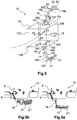
- the figure 3 shows a more detailed representation of a satellite according to a particularly advantageous embodiment of the invention.
- the satellite 10 is associated with a satellite reference centered on a center of mass O of the satellite 10 and comprising three axes X, Y, Z. More particularly, the axis X is parallel to a vector the speed of the satellite 10 in an inertial frame, the Z axis is directed towards the center of the Earth, and the Y axis is orthogonal to the X and Z axes.
- Each of the X, Y and Z axes of the satellite reference vector is associated with vectors units respectively ux, uy and uz.
- the unit vector ux corresponds to the velocity vector normalized by the norm of said velocity vector
- the unit vector uz is oriented from the center of mass O of the satellite 10 to the center of the Earth
- the unit vector uy is oriented so that the set (ux, uy, uz) is a direct orthonormal basis of the satellite reference.
- the body 20 of the satellite 10 is substantially in the form of a rectangular parallelepiped.
- the body 20 thus comprises six faces two by two parallel.
- the satellite 10 also comprises a set of actuators adapted to control the orbit and the attitude of said satellite 10, and a control device (not shown in the figures) of said actuators.
- the satellite 10 preferably comprises a kinetic moment storage device.
- the point of attachment of the fixed orientation thruster 16 to the anti-Earth face 102 of the satellite 10 corresponds substantially to the orthogonal projection of the theoretical center of mass of the satellite 10 on said anti-Earth face 102.
- the moment applied to the satellite 10 by the fixed orientation thruster 16 is substantially zero as long as the center actual mass O of the satellite 10 is close to the theoretical center of mass.
- the satellite 10 may comprise, according to other examples, several thrusters 16 of fixed orientation relative to the satellite 10.
- the fixed orientation thruster 16 may be implemented to transfer the satellite 10 from the initial orbit into its geostationary mission orbit, or, at station, to control the eccentricity of the orbit. It can be activated simultaneously with the electric thrusters 21, 21 ', 22, 22', and / or during dedicated eccentricity control maneuvers, distinct from the N / S and E / O control maneuvers of the orbit.
- the orbit control of the satellite 10 is carried out, at the level of a satellite control device 10, by controlling the propulsion means and the displacement means according to a maneuvering plane comprising orbit control maneuvers during which the propulsion means are activated.
- the displacement means comprise two articulated arms 14, 15, each articulated arm 14, 15 carrying two electric thrusters 21, 21 'and 22, 22'.
- the articulated arms 14, 15 are arranged respectively on the south face 103 and the north face 104 of the body 20 of the satellite 10.
- the articulated arms 14, 15 are for example used for the South control and the North control respectively. tilting the orbit of the satellite 10, alternately activating either a thruster 21, 21 'or a thruster 22, 22'.
- the articulated arm 14 is preferably fixed to the south face 103 at a fixed point which is offset, along the Z axis, relative to the orthogonal projection of the theoretical center of mass O of the satellite 10 on said south face 103.
- the articulated arm 15 is preferably fixed to the north face 104 at a fixed point which is offset along the Z axis relative to the orthogonal projection of the theoretical center of mass O of the satellite 10 on said north face 104.
- the thrust force of the steerable thrust direction electric thrusters respectively 21, 21 ', and 22, 22' comprises in north / south control a component along the Z axis without forming a moment.
- Such a configuration is however not limited to the invention.
- Each of the two articulated arms 14, 15 comprises at least three joints respectively 141, 142, 143 and 151, 152, 153. Each of these joints comprises at least one degree of freedom in rotation about an axis of rotation.
- the joints 141 and 142, and 151 and 152 are interconnected by a connection respectively 144 and 154, while the joints 142 and 143, and 152 and 153, are interconnected by a connection respectively 145 and 155.
- a plate 146, 156 extends from the terminal joint 143, 153 of each articulated arm 14, 15 and carries the electric thrusters 21, 21 'and 22, 22'.
- Each articulated arm 14, 15 offers three degrees of freedom to modify, with respect to the N / S control position, the thrust direction and the point of application of the thrust force of the electric thrusters that it carries.
- the control device controls the angles of rotation of the joints 141, 151, 142, 152, and 143, 153, designated respectively by ⁇ 1, ⁇ 2 and ⁇ 3.
- the various electric thrusters of the satellite 10 according to the invention can be implemented both for the transfer phase of the satellite of an initial orbit, in particular an injection orbit into which it has been injected by a launcher vehicle, into its geostationary mission orbit, only for orbit control and attitude of the satellite station.
- the fixed orientation electric thruster 16 with respect to the satellite 10 has a thrust of fixed direction, substantially aligned along the Z axis of the satellite, as indicated schematically in FIG. figure 4 .
- This fixed orientation electrical thruster 16 may be implemented during the orbit transfer phase, in nominal operation, to reduce the transfer time, or in the event of failure of one or more thrust steering thrusters. steerable 21, 21 ', 22, 22'.
- the steerable thrust direction electrical thrusters 21, 21 ', 22, 22' can be implemented for both the orbit transfer phase and the orbit control and attitude phase of the satellite 10. Indeed, they are moved in the satellite reference, so as to orient their direction of thrust adequately, for example along the Z axis, in the same direction.
- the Figures 5a and 5b illustrate examples of positioning of steerable thrust direction electric thrusters 21, 21 'carried by the articulated arm 14.
- the electric thrusters 21, 21 ' are placed in a configuration in which they are capable of exerting thrust along the Z axis.
- the electric thrusters 21, 21 ' are placed in a configuration in which they are able to exert thrust in a different direction in the satellite reference.
- the satellite 10 further comprises at least two power supply units of an electric thruster, referred to as PPU in the remainder of this description, which are conventional in themselves.
- PPU an electric thruster
- it comprises at least three PPUs 24, 25, 26, and an electrical interconnection network 23, an exemplary embodiment of which is illustrated in FIG. figure 6 , connecting each of these PPUs to one or more electric thrusters of the satellite 10.
- connection between the PPUs and the electric thrusters is carried out by conventional electrical wiring in itself.
- the satellite 10 having the above characteristics advantageously has a particularly high degree of robustness, and can easily adapt to a large number of various faults, including double faults, so that its operation, and in particular the duration of its mission, is little or not impacted by the breakdowns, and this for a difference in mass and cost compared with satellites of the relatively weak prior art.
- This advantage is added to that of reducing the duration of the orbit transfer phase, from the injection orbit to the geostationary orbit, which makes it possible in particular to minimize the exposure time of the satellite 10 to radiation. Van Allen belts.
- the satellite 10 can be controlled remotely by a control device, in particular on the ground, in a conventional manner in itself .
- This remote control device is configured to control the different phases implemented by the satellite 10.
- the control device and the satellite 10 each comprise conventional means of remote communication.
- the control device is adapted to determine control signals that are sent to the satellite 10. These control signals are for example determined as a function of measurement signals received from the satellite 10, which are determined by different sensors (gyroscope, star sensor, etc.) of the latter.
- the satellite 10 comprises for example at least one processor and at least one electronic memory in which is stored a computer program product, in the form of a set of program code instructions to be executed to implement the various steps of a satellite control method 10.
- control device also comprises one or more programmable logic circuits, of FPGA, PLD, etc. type, and / or specialized integrated circuits (ASIC) adapted to implement all or part of said steps of the control method.
- control device comprises a set of means configured in software (specific computer program product) and / or hardware (FPGA, PLD, ASIC, etc.) to implement the various steps of a method of transfer of the satellite 10 from the injection orbit into the mission orbit, and then a method of controlling the orbit and attitude of the satellite 10 in the mission orbit.
Landscapes
- Engineering & Computer Science (AREA)
- Remote Sensing (AREA)
- Chemical & Material Sciences (AREA)
- Combustion & Propulsion (AREA)
- Aviation & Aerospace Engineering (AREA)
- Radar, Positioning & Navigation (AREA)
- Power Engineering (AREA)
- Control Of Position, Course, Altitude, Or Attitude Of Moving Bodies (AREA)
Claims (16)
- Satellit (10), der dazu bestimmt ist, in einer Einsatzumlaufbahn um einen Himmelskörper positioniert zu werden, der eine so genannte erdzugewandte Seite (101), die dazu bestimmt ist, der Erde gegenüber angeordnet zu sein, wenn der Satellit (10) in Position ist, und eine gegenüberliegende erdabgewandte Seite (102) aufweist, wobei der Satellit (10) ein Satelliten-Koordinatensystem definiert, das auf einen Massenmittelpunkt des Satelliten zentriert ist und drei Achsen X, Y und Z aufweist, wobei die Z-Achse dazu bestimmt ist, zur Erde gerichtet zu sein, wenn der Satellit (10) in Position ist, wobei der Satellit (10) aufweist:- Antriebseinrichtungen, die ein erstes elektrisches Triebwerk mit ausrichtbarer Schubrichtung (21) und ein zweites elektrisches Triebwerk mit ausrichtbarer Schubrichtung (22) aufweisen, wobei die Antriebseinrichtungen außerdem ein elektrisches Triebwerk (16) mit fester Ausrichtung bezüglich des Satelliten mit einer gemäß der Z-Achse fluchtend ausgerichteten Schublinie aufweisen,dadurch gekennzeichnet, dass- die Schublinie des elektrischen Triebwerks mit fester Ausrichtung (16) durch den Massenmittelpunkt des Satelliten geht, dass der Satellit (10) aufweist:und dass das elektrische Verbindungsnetz (23) jede der ersten Versorgungseinheit eines elektrischen Triebwerks (26) und der zweiten Versorgungseinheit eines elektrischen Triebwerks (25) mit dem elektrischen Triebwerk mit fester Ausrichtung (16) verbindet, so dass jede der Versorgungseinheiten (25, 26) entweder das zugeordnete elektrische Triebwerk mit ausrichtbarer Schubrichtung (22, 21) oder das elektrische Triebwerk mit fester Ausrichtung (16) versorgen kann.- mindestens zwei Versorgungseinheiten eines elektrischen Triebwerks (25, 26) und ein elektrisches Verbindungsnetz (23), das eine erste Versorgungseinheit eines elektrischen Triebwerks (26) mit dem ersten elektrischen Triebwerk mit ausrichtbarer Schubrichtung (21) und eine zweite Versorgungseinheit eines elektrischen Triebwerks (25) mit dem zweiten elektrischen Triebwerk mit ausrichtbarer Schubrichtung (22) verbindet,
- Satellit (10) nach Anspruch 1, wobei das elektrische Triebwerk (16) mit fester Ausrichtung auf der erdabgewandten Seite (102) des Satelliten (10) angeordnet ist.
- Satellit (10) nach einem der Ansprüche 1 bis 2, der mindestens drei Versorgungseinheiten eines elektrischen Triebwerks (24, 25, 26) und ein elektrisches Verbindungsnetz (23) aufweist, das jede der Versorgungseinheiten eines elektrischen Triebwerks mit mindestens einem elektrischen Triebwerk der Antriebseinrichtungen derart verbindet, dass gleichzeitig das elektrische Triebwerk mit fester Ausrichtung (16) und zwei elektrische Triebwerke mit ausrichtbarer Schubrichtung in Betrieb genommen werden können.
- Satellit (10) nach einem der Ansprüche 1 bis 3, wobei die Antriebseinrichtungen ein zusätzliches erstes elektrisches Triebwerk mit ausrichtbarer Schubrichtung (21') aufweisen, das auf der gleichen Seite (103) des Satelliten wie das erste elektrische Triebwerk mit ausrichtbarer Schubrichtung (21) angeordnet ist.
- Satellit (10) nach Anspruch 4, wobei die Antriebseinrichtungen ein zusätzliches zweites elektrisches Triebwerk mit ausrichtbarer Schubrichtung (22') aufweisen, das auf der gleichen Seite (104) des Satelliten wie das zweite elektrische Triebwerk mit ausrichtbarer Schubrichtung (22) angeordnet ist.
- Satellit (10) nach Anspruch 5, der eine dritte Versorgungseinheit eines elektrischen Triebwerks (24) und ein elektrisches Verbindungsnetz aufweist, das die dritte Versorgungseinheit eines elektrischen Triebwerks (24) mit dem zusätzlichen ersten elektrischen Triebwerk mit ausrichtbarer Schubrichtung (21') und mit dem zusätzlichen zweiten elektrischen Triebwerk mit ausrichtbarer Schubrichtung (22') verbindet.
- Satellit (10) nach einem der Ansprüche 1 bis 6, der eine Vielzahl elektrischer Triebwerke (16) mit fester Ausrichtung bezüglich des Satelliten (10) aufweist, mit der Schublinie gemäß der Z-Achse fluchtend ausgerichtet und im Wesentlichen durch den Massenmittelpunkt des Satelliten verlaufend, die auf der gleichen Seite (102) des Satelliten (10) angeordnet sind.
- Satellit (10) nach einem der Ansprüche 1 bis 7, der Einrichtungen zur Verschiebung jedes der elektrischen Triebwerke mit ausrichtbarer Schubrichtung (21, 21', 22, 22') der Antriebseinrichtungen im Satelliten-Koordinatensystem aufweist.
- Satellit (10) nach Anspruch 8, wobei die Verschiebungseinrichtungen den auf der gleichen Seite des Satelliten angeordneten elektrischen Triebwerken mit ausrichtbarer Schubrichtung gemeinsam sind.
- Satellit (10) nach einem der Ansprüche 8 bis 9, wobei die Verschiebungseinrichtungen jedes der elektrischen Triebwerke mit ausrichtbarer Schubrichtung (21, 21', 22, 22') zwei Gelenkarme (14, 15) aufweisen, die je ein elektrisches Triebwerk mit ausrichtbarer Schubrichtung (21, 22) und ggf. das auf der gleichen Seite des Satelliten (21', 22') angeordnete elektrische Triebwerk mit ausrichtbarer Schubrichtung tragen, wobei jeder der zwei Gelenkarme (14, 15) mindestens drei Gelenke (141, 142, 143 und 151, 152, 153) aufweist, die je mindestens einen Drehfreiheitsgrad um eine Drehachse aufweisen.
- Satellit (10) nach einem der Ansprüche 1 bis 10, wobei die elektrischen Triebwerke (16, 21, 21', 22, 22') der Antriebseinrichtungen alle mit den gleichen Versorgungseinheiten eines elektrischen Triebwerks kompatibel und vorzugsweise gleich sind.
- Verfahren zur Verlagerung eines Satelliten (10) nach einem der Ansprüche 1 bis 11 von einer ursprünglichen Umlaufbahn in eine Einsatzumlaufbahn des Satelliten (10) um einen Himmelskörper, dadurch gekennzeichnet, dass es einen Schritt des Antriebs des Satelliten (10) mittels gleichzeitig des elektrischen Triebwerks (16) mit fester Ausrichtung bezüglich des Satelliten (10) und mindestens eines elektrischen Triebwerks mit ausrichtbarer Schubrichtung (21, 21', 22, 22') enthält.
- Verlagerungsverfahren nach Anspruch 12, gemäß dem, da der Satellit (10) mindestens drei Versorgungseinheiten eines elektrischen Triebwerks (24, 25, 26) und ein elektrisches Verbindungsnetz (23) aufweist, das jede der Versorgungseinheiten eines elektrischen Triebwerks mit mindestens einem elektrischen Triebwerk der Antriebseinrichtungen derart verbindet, dass das elektrische Triebwerk mit fester Ausrichtung (16) und zwei elektrische Triebwerke mit ausrichtbarer Schubrichtung gleichzeitig in Betrieb genommen werden können, das Verlagerungsverfahren einen Schritt des Antriebs des Satelliten (10) mittels gleichzeitig des elektrischen Triebwerks mit fester Ausrichtung (16) und mindestens zwei elektrischer Triebwerke mit ausrichtbarer Schubrichtung (21, 21', 22, 22') enthält, die auf unterschiedlichen Seiten (103, 104) des Satelliten angeordnet sind.
- Verfahren zur Kontrolle der Umlaufbahn und Fluglage eines Satelliten (10) nach einem der Ansprüche 1 bis 11 in einer Einsatzumlaufbahn um einen Himmelskörper, dadurch gekennzeichnet, dass es einen Schritt des Antriebs des Satelliten (10) durch das elektrische Triebwerk (16) mit fester Ausrichtung bezüglich des Satelliten (10) enthält.
- Verfahren zur Fernsteuerung eines Satelliten (10) zur Durchführung der Schritte eines Verlagerungsverfahrens nach einem der Ansprüche 12 bis 13 und/oder der Schritte eines Verfahrens zur Kontrolle der Umlaufbahn und Fluglage nach Anspruch 14, gemäß dem der Satellit (10) von einer Steuervorrichtung ferngesteuert wird, wobei Steuersignale nacheinander bestimmt und von der Steuervorrichtung zur Durchführung der Schritte an den Satelliten (10) geschickt werden.
- Computerprogrammprodukt, dadurch gekennzeichnet, dass es eine Einheit von Programmcodeanweisungen aufweist, die, wenn sie von einem Prozessor ausgeführt werden, ein Verlagerungsverfahren eines Satelliten (10) nach einem der Ansprüche 12 bis 13 und/oder ein Verfahren zur Kontrolle der Umlaufbahn und der Fluglage eines Satelliten (10) nach Anspruch 14 durchführen.
Applications Claiming Priority (2)
| Application Number | Priority Date | Filing Date | Title |
|---|---|---|---|
| FR1551034A FR3032427B1 (fr) | 2015-02-10 | 2015-02-10 | Satellite a moyens de propulsion electriques, procede de mise a poste d'un tel satellite et procede de maintien a poste dudit satellite |
| PCT/EP2016/052710 WO2016128389A1 (fr) | 2015-02-10 | 2016-02-09 | Satellite à moyens de propulsion électriques, procédé de mise à poste d'un tel satellite et procédé de maintien à poste dudit satellite |
Publications (2)
| Publication Number | Publication Date |
|---|---|
| EP3201090A1 EP3201090A1 (de) | 2017-08-09 |
| EP3201090B1 true EP3201090B1 (de) | 2017-12-13 |
Family
ID=53298505
Family Applications (1)
| Application Number | Title | Priority Date | Filing Date |
|---|---|---|---|
| EP16705070.7A Active EP3201090B1 (de) | 2015-02-10 | 2016-02-09 | Satellit mit elektrischer antriebsvorrichtung, verfahren zur platzierung solch eines satelliten in einer station und verfahren zum halten des besagten satelliten in seiner station |
Country Status (5)
| Country | Link |
|---|---|
| US (1) | US9926087B2 (de) |
| EP (1) | EP3201090B1 (de) |
| ES (1) | ES2661024T3 (de) |
| FR (1) | FR3032427B1 (de) |
| WO (1) | WO2016128389A1 (de) |
Families Citing this family (17)
| Publication number | Priority date | Publication date | Assignee | Title |
|---|---|---|---|---|
| FR3022530B1 (fr) * | 2014-06-19 | 2018-03-02 | Airbus Defence And Space Sas | Procede de controle d'orbite d'un satellite en orbite terrestre, satellite et systeme de controle d'orbite d'un tel satellite |
| US10046867B2 (en) * | 2015-09-18 | 2018-08-14 | Orbital Atk, Inc. | Maneuvering system for earth orbiting satellites with electric thrusters |
| US10005568B2 (en) | 2015-11-13 | 2018-06-26 | The Boeing Company | Energy efficient satellite maneuvering |
| US10569909B2 (en) * | 2016-03-30 | 2020-02-25 | The Boeing Company | Systems and methods for satellite orbit and momentum control |
| US20190300207A1 (en) * | 2016-09-29 | 2019-10-03 | Mitsubishi Electric Corporation | Artificial satellite and satellite propulsion method |
| EP3521179B1 (de) * | 2016-09-29 | 2021-05-26 | Mitsubishi Electric Corporation | Ausrichtungsmechanismus |
| US10625882B2 (en) * | 2017-03-06 | 2020-04-21 | Effective Space Solutions Ltd. | Service satellite for providing in-orbit services using variable thruster control |
| CN117262238A (zh) * | 2017-07-21 | 2023-12-22 | 诺思路·格鲁曼系统公司 | 航天器服务装置及相关组件、系统和方法 |
| RU2714286C1 (ru) * | 2018-11-30 | 2020-02-13 | Российская Федерация, от имени которой выступает Министерство обороны Российской Федерации | Способ приведения космического аппарата к долготе стояния на геостационарной орбите |
| CN109823574B (zh) * | 2019-02-18 | 2019-12-17 | 中国科学院国家空间科学中心 | 一种星载间隙性工作载荷系统 |
| FR3110144A1 (fr) * | 2020-05-12 | 2021-11-19 | Airbus Defence And Space Sas | Procédé de contrôle d’orbite et de désaturation d’un satellite au moyen d’un unique bras articulé portant une unité de propulsion |
| FR3110549A1 (fr) * | 2020-05-19 | 2021-11-26 | Airbus Defence And Space Sas | Procédé d’optimisation du transfert d’orbite d’un engin spatial à propulsion électrique et satellite mettant en œuvre ledit procédé |
| US12077323B2 (en) | 2020-07-02 | 2024-09-03 | Airbus Defence And Space Sas | Method for orbit control and desaturation of a satellite by means of articulated arms supporting propulsion units |
| CN113202706A (zh) * | 2021-04-25 | 2021-08-03 | 上海宇航系统工程研究所 | 一种用于geo轨道卫星的霍尔电推进系统 |
| US12097979B1 (en) * | 2023-03-01 | 2024-09-24 | Astroscale Israel, Ltd. | Satellite for rendezvous and docking using electric propulsion thrusters |
| DE102023136422B3 (de) * | 2023-12-21 | 2025-06-18 | Deutsches Zentrum für Luft- und Raumfahrt e.V. | Weltraumhandhabungsvorrichtung |
| CN120606972A (zh) * | 2025-07-14 | 2025-09-09 | 上海大学 | 电推进器、飞行器及集群控制方法 |
Family Cites Families (11)
| Publication number | Priority date | Publication date | Assignee | Title |
|---|---|---|---|---|
| FR2669887B1 (fr) * | 1990-11-30 | 1995-06-02 | Aerospatiale | Procede de controle d'attitude en tangage d'un satellite grace a la pression de radiation solaire et satellite adapte a sa mise en óoeuvre. |
| GB9127433D0 (en) * | 1991-12-27 | 1992-02-19 | Matra Marconi Space Uk | Propulsion system for spacecraft |
| US5443231A (en) | 1993-11-17 | 1995-08-22 | Hughes Aircraft Company | Method and apparatus for a satellite station keeping |
| US5947421A (en) * | 1997-07-09 | 1999-09-07 | Beattie; John R. | Electrostatic propulsion systems and methods |
| US6032904A (en) * | 1998-02-23 | 2000-03-07 | Space Systems/Loral, Inc. | Multiple usage thruster mounting configuration |
| FR2990193B1 (fr) | 2012-05-03 | 2015-01-09 | Thales Sa | Systeme de propulsion pour controle d'orbite et controle d'attitude de satellite |
| FR2990930B1 (fr) | 2012-05-25 | 2014-06-27 | Thales Sa | Systeme de propulsion pour controle d'orbite et controle d'attitude de satellite |
| FR2997386B1 (fr) * | 2012-10-31 | 2015-05-29 | Thales Sa | Dispositif de propulsion optimise pour controle d'orbite et controle d'attitude de satellite |
| FR3006670B1 (fr) * | 2013-06-07 | 2015-05-29 | Thales Sa | Systeme de propulsion en deux modules pour controle d'orbite et controle d'attitude de satellite |
| FR3006671B1 (fr) * | 2013-06-07 | 2015-05-29 | Thales Sa | Systeme de propulsion en quatre modules pour controle d'orbite et controle d'attitude de satellite |
| FR3022530B1 (fr) * | 2014-06-19 | 2018-03-02 | Airbus Defence And Space Sas | Procede de controle d'orbite d'un satellite en orbite terrestre, satellite et systeme de controle d'orbite d'un tel satellite |
-
2015
- 2015-02-10 FR FR1551034A patent/FR3032427B1/fr active Active
-
2016
- 2016-02-09 EP EP16705070.7A patent/EP3201090B1/de active Active
- 2016-02-09 US US15/549,165 patent/US9926087B2/en active Active
- 2016-02-09 ES ES16705070.7T patent/ES2661024T3/es active Active
- 2016-02-09 WO PCT/EP2016/052710 patent/WO2016128389A1/fr not_active Ceased
Also Published As
| Publication number | Publication date |
|---|---|
| US20180029727A1 (en) | 2018-02-01 |
| FR3032427B1 (fr) | 2017-03-10 |
| EP3201090A1 (de) | 2017-08-09 |
| US9926087B2 (en) | 2018-03-27 |
| ES2661024T3 (es) | 2018-03-27 |
| WO2016128389A1 (fr) | 2016-08-18 |
| FR3032427A1 (fr) | 2016-08-12 |
Similar Documents
| Publication | Publication Date | Title |
|---|---|---|
| EP3201090B1 (de) | Satellit mit elektrischer antriebsvorrichtung, verfahren zur platzierung solch eines satelliten in einer station und verfahren zum halten des besagten satelliten in seiner station | |
| EP3381813B1 (de) | Satellit, der elektrische antriebsmittel umfasst, die von bewegungsmitteln und zusätzlichen elektrischen antriebsmitteln mit fester ausrichtung getragen werden | |
| EP3083406B1 (de) | Verfahren und system zur übertragung eines satelliten aus einer ersten umlaufbahn in eine missionsumlaufbahn | |
| EP2810875B1 (de) | Bimodulares Antriebssystem für Orbit- und Fluglageregelung eines Satelliten | |
| EP2666723B1 (de) | Antriebssystem für die Kontrolle der Umlaufbahn und der Lage von Satelliten | |
| EP2660154B1 (de) | Antriebssystem für die Kontrolle der Umlaufbahn und der Lageregelung eines Satelliten | |
| EP2690020B1 (de) | Verfahren zur Reduzierung des Drehimpulses und zur Fluglageregelung eines Raumfahrzeugs | |
| EP0799768B1 (de) | System und Verfahren um mit Triebwerken mit hohen spezifischen Impulsen versehen ein Raumfahrzeug in eine Umlaufbahn zu bringen | |
| EP2810876B1 (de) | Viermodulares Antriebssystem für Orbit- und Fluglageregelung eines Satelliten | |
| FR2775251A1 (fr) | Configuration du montage du propulseur a usage multiple | |
| WO1992009479A2 (fr) | Procede de controle d'attitude en tangage d'un satellite grace a la pression de radiation solaire et satellite adapte a sa mise en ×uvre | |
| EP3038923B1 (de) | Verfahren und vorrichtung für elektrischen satellitenantrieb | |
| EP2878539B1 (de) | Düsensystem und verfahren zur kontrolle der umlaufbahn und des verhaltens für geostationären satelliten | |
| FR2999537A1 (fr) | Systeme et procede de capture et d'elimination d'un debris spatial | |
| EP4153490B1 (de) | Verfahren zur optimierung des orbitalen transfers eines elektrisch angetriebenen raumfahrzeugs und das verfahren verwendender satellit | |
| EP0047211B1 (de) | Verfahren zum Verändern der Umlaufbahn eines Satelliten, insbesondere zur Injektion in eine geostationäre Umlaufbahn, und für dieses Verfahren geeigneter Satellit | |
| EP3956230B1 (de) | Verfahren zur umlaufbahnsteuerung und -desaturation eines satelliten mittels einzelgelenkarm, der eine antriebseinheit trägt | |
| EP3959142B1 (de) | Verfahren zur umlaufbahnsteuerung und -desaturation eines satelliten mittels gelenkarmen, die eine antriebseinheit tragen |
Legal Events
| Date | Code | Title | Description |
|---|---|---|---|
| PUAI | Public reference made under article 153(3) epc to a published international application that has entered the european phase |
Free format text: ORIGINAL CODE: 0009012 |
|
| 17P | Request for examination filed |
Effective date: 20170505 |
|
| AK | Designated contracting states |
Kind code of ref document: A1 Designated state(s): AL AT BE BG CH CY CZ DE DK EE ES FI FR GB GR HR HU IE IS IT LI LT LU LV MC MK MT NL NO PL PT RO RS SE SI SK SM TR |
|
| AX | Request for extension of the european patent |
Extension state: BA ME |
|
| GRAP | Despatch of communication of intention to grant a patent |
Free format text: ORIGINAL CODE: EPIDOSNIGR1 |
|
| GRAS | Grant fee paid |
Free format text: ORIGINAL CODE: EPIDOSNIGR3 |
|
| INTG | Intention to grant announced |
Effective date: 20171004 |
|
| GRAA | (expected) grant |
Free format text: ORIGINAL CODE: 0009210 |
|
| DAV | Request for validation of the european patent (deleted) | ||
| DAX | Request for extension of the european patent (deleted) | ||
| RAP1 | Party data changed (applicant data changed or rights of an application transferred) |
Owner name: AIRBUS DEFENCE AND SPACE SAS |
|
| REG | Reference to a national code |
Ref country code: GB Ref legal event code: FG4D Free format text: NOT ENGLISH |
|
| REG | Reference to a national code |
Ref country code: AT Ref legal event code: REF Ref document number: 954112 Country of ref document: AT Kind code of ref document: T Effective date: 20171215 Ref country code: CH Ref legal event code: EP |
|
| REG | Reference to a national code |
Ref country code: IE Ref legal event code: FG4D Free format text: LANGUAGE OF EP DOCUMENT: FRENCH |
|
| REG | Reference to a national code |
Ref country code: DE Ref legal event code: R096 Ref document number: 602016001096 Country of ref document: DE |
|
| REG | Reference to a national code |
Ref country code: FR Ref legal event code: PLFP Year of fee payment: 3 |
|
| REG | Reference to a national code |
Ref country code: ES Ref legal event code: FG2A Ref document number: 2661024 Country of ref document: ES Kind code of ref document: T3 Effective date: 20180327 |
|
| REG | Reference to a national code |
Ref country code: NL Ref legal event code: MP Effective date: 20171213 |
|
| PG25 | Lapsed in a contracting state [announced via postgrant information from national office to epo] |
Ref country code: NO Free format text: LAPSE BECAUSE OF FAILURE TO SUBMIT A TRANSLATION OF THE DESCRIPTION OR TO PAY THE FEE WITHIN THE PRESCRIBED TIME-LIMIT Effective date: 20180313 Ref country code: FI Free format text: LAPSE BECAUSE OF FAILURE TO SUBMIT A TRANSLATION OF THE DESCRIPTION OR TO PAY THE FEE WITHIN THE PRESCRIBED TIME-LIMIT Effective date: 20171213 Ref country code: SE Free format text: LAPSE BECAUSE OF FAILURE TO SUBMIT A TRANSLATION OF THE DESCRIPTION OR TO PAY THE FEE WITHIN THE PRESCRIBED TIME-LIMIT Effective date: 20171213 |
|
| REG | Reference to a national code |
Ref country code: AT Ref legal event code: MK05 Ref document number: 954112 Country of ref document: AT Kind code of ref document: T Effective date: 20171213 |
|
| PG25 | Lapsed in a contracting state [announced via postgrant information from national office to epo] |
Ref country code: GR Free format text: LAPSE BECAUSE OF FAILURE TO SUBMIT A TRANSLATION OF THE DESCRIPTION OR TO PAY THE FEE WITHIN THE PRESCRIBED TIME-LIMIT Effective date: 20180314 Ref country code: BG Free format text: LAPSE BECAUSE OF FAILURE TO SUBMIT A TRANSLATION OF THE DESCRIPTION OR TO PAY THE FEE WITHIN THE PRESCRIBED TIME-LIMIT Effective date: 20180313 Ref country code: HR Free format text: LAPSE BECAUSE OF FAILURE TO SUBMIT A TRANSLATION OF THE DESCRIPTION OR TO PAY THE FEE WITHIN THE PRESCRIBED TIME-LIMIT Effective date: 20171213 Ref country code: RS Free format text: LAPSE BECAUSE OF FAILURE TO SUBMIT A TRANSLATION OF THE DESCRIPTION OR TO PAY THE FEE WITHIN THE PRESCRIBED TIME-LIMIT Effective date: 20171213 Ref country code: LV Free format text: LAPSE BECAUSE OF FAILURE TO SUBMIT A TRANSLATION OF THE DESCRIPTION OR TO PAY THE FEE WITHIN THE PRESCRIBED TIME-LIMIT Effective date: 20171213 |
|
| PG25 | Lapsed in a contracting state [announced via postgrant information from national office to epo] |
Ref country code: NL Free format text: LAPSE BECAUSE OF FAILURE TO SUBMIT A TRANSLATION OF THE DESCRIPTION OR TO PAY THE FEE WITHIN THE PRESCRIBED TIME-LIMIT Effective date: 20171213 |
|
| PG25 | Lapsed in a contracting state [announced via postgrant information from national office to epo] |
Ref country code: CZ Free format text: LAPSE BECAUSE OF FAILURE TO SUBMIT A TRANSLATION OF THE DESCRIPTION OR TO PAY THE FEE WITHIN THE PRESCRIBED TIME-LIMIT Effective date: 20171213 Ref country code: CY Free format text: LAPSE BECAUSE OF FAILURE TO SUBMIT A TRANSLATION OF THE DESCRIPTION OR TO PAY THE FEE WITHIN THE PRESCRIBED TIME-LIMIT Effective date: 20171213 Ref country code: EE Free format text: LAPSE BECAUSE OF FAILURE TO SUBMIT A TRANSLATION OF THE DESCRIPTION OR TO PAY THE FEE WITHIN THE PRESCRIBED TIME-LIMIT Effective date: 20171213 Ref country code: SK Free format text: LAPSE BECAUSE OF FAILURE TO SUBMIT A TRANSLATION OF THE DESCRIPTION OR TO PAY THE FEE WITHIN THE PRESCRIBED TIME-LIMIT Effective date: 20171213 |
|
| PG25 | Lapsed in a contracting state [announced via postgrant information from national office to epo] |
Ref country code: RO Free format text: LAPSE BECAUSE OF FAILURE TO SUBMIT A TRANSLATION OF THE DESCRIPTION OR TO PAY THE FEE WITHIN THE PRESCRIBED TIME-LIMIT Effective date: 20171213 Ref country code: IS Free format text: LAPSE BECAUSE OF FAILURE TO SUBMIT A TRANSLATION OF THE DESCRIPTION OR TO PAY THE FEE WITHIN THE PRESCRIBED TIME-LIMIT Effective date: 20180413 Ref country code: SM Free format text: LAPSE BECAUSE OF FAILURE TO SUBMIT A TRANSLATION OF THE DESCRIPTION OR TO PAY THE FEE WITHIN THE PRESCRIBED TIME-LIMIT Effective date: 20171213 Ref country code: PL Free format text: LAPSE BECAUSE OF FAILURE TO SUBMIT A TRANSLATION OF THE DESCRIPTION OR TO PAY THE FEE WITHIN THE PRESCRIBED TIME-LIMIT Effective date: 20171213 Ref country code: AT Free format text: LAPSE BECAUSE OF FAILURE TO SUBMIT A TRANSLATION OF THE DESCRIPTION OR TO PAY THE FEE WITHIN THE PRESCRIBED TIME-LIMIT Effective date: 20171213 |
|
| REG | Reference to a national code |
Ref country code: DE Ref legal event code: R097 Ref document number: 602016001096 Country of ref document: DE |
|
| PG25 | Lapsed in a contracting state [announced via postgrant information from national office to epo] |
Ref country code: MT Free format text: LAPSE BECAUSE OF FAILURE TO SUBMIT A TRANSLATION OF THE DESCRIPTION OR TO PAY THE FEE WITHIN THE PRESCRIBED TIME-LIMIT Effective date: 20171213 Ref country code: MC Free format text: LAPSE BECAUSE OF FAILURE TO SUBMIT A TRANSLATION OF THE DESCRIPTION OR TO PAY THE FEE WITHIN THE PRESCRIBED TIME-LIMIT Effective date: 20171213 |
|
| PLBE | No opposition filed within time limit |
Free format text: ORIGINAL CODE: 0009261 |
|
| STAA | Information on the status of an ep patent application or granted ep patent |
Free format text: STATUS: NO OPPOSITION FILED WITHIN TIME LIMIT |
|
| 26N | No opposition filed |
Effective date: 20180914 |
|
| REG | Reference to a national code |
Ref country code: IE Ref legal event code: MM4A |
|
| REG | Reference to a national code |
Ref country code: BE Ref legal event code: MM Effective date: 20180228 |
|
| PG25 | Lapsed in a contracting state [announced via postgrant information from national office to epo] |
Ref country code: DK Free format text: LAPSE BECAUSE OF FAILURE TO SUBMIT A TRANSLATION OF THE DESCRIPTION OR TO PAY THE FEE WITHIN THE PRESCRIBED TIME-LIMIT Effective date: 20171213 |
|
| PG25 | Lapsed in a contracting state [announced via postgrant information from national office to epo] |
Ref country code: IE Free format text: LAPSE BECAUSE OF NON-PAYMENT OF DUE FEES Effective date: 20180209 |
|
| PG25 | Lapsed in a contracting state [announced via postgrant information from national office to epo] |
Ref country code: BE Free format text: LAPSE BECAUSE OF NON-PAYMENT OF DUE FEES Effective date: 20180228 |
|
| REG | Reference to a national code |
Ref country code: CH Ref legal event code: PL |
|
| PG25 | Lapsed in a contracting state [announced via postgrant information from national office to epo] |
Ref country code: CH Free format text: LAPSE BECAUSE OF NON-PAYMENT OF DUE FEES Effective date: 20190228 Ref country code: LI Free format text: LAPSE BECAUSE OF NON-PAYMENT OF DUE FEES Effective date: 20190228 |
|
| PG25 | Lapsed in a contracting state [announced via postgrant information from national office to epo] |
Ref country code: TR Free format text: LAPSE BECAUSE OF FAILURE TO SUBMIT A TRANSLATION OF THE DESCRIPTION OR TO PAY THE FEE WITHIN THE PRESCRIBED TIME-LIMIT Effective date: 20171213 |
|
| PG25 | Lapsed in a contracting state [announced via postgrant information from national office to epo] |
Ref country code: PT Free format text: LAPSE BECAUSE OF FAILURE TO SUBMIT A TRANSLATION OF THE DESCRIPTION OR TO PAY THE FEE WITHIN THE PRESCRIBED TIME-LIMIT Effective date: 20171213 |
|
| PG25 | Lapsed in a contracting state [announced via postgrant information from national office to epo] |
Ref country code: HU Free format text: LAPSE BECAUSE OF FAILURE TO SUBMIT A TRANSLATION OF THE DESCRIPTION OR TO PAY THE FEE WITHIN THE PRESCRIBED TIME-LIMIT; INVALID AB INITIO Effective date: 20160209 Ref country code: MK Free format text: LAPSE BECAUSE OF NON-PAYMENT OF DUE FEES Effective date: 20171213 Ref country code: LT Free format text: LAPSE BECAUSE OF FAILURE TO SUBMIT A TRANSLATION OF THE DESCRIPTION OR TO PAY THE FEE WITHIN THE PRESCRIBED TIME-LIMIT Effective date: 20171213 |
|
| PG25 | Lapsed in a contracting state [announced via postgrant information from national office to epo] |
Ref country code: AL Free format text: LAPSE BECAUSE OF FAILURE TO SUBMIT A TRANSLATION OF THE DESCRIPTION OR TO PAY THE FEE WITHIN THE PRESCRIBED TIME-LIMIT Effective date: 20171213 |
|
| PG25 | Lapsed in a contracting state [announced via postgrant information from national office to epo] |
Ref country code: SI Free format text: LAPSE BECAUSE OF NON-PAYMENT OF DUE FEES Effective date: 20180209 |
|
| PGFP | Annual fee paid to national office [announced via postgrant information from national office to epo] |
Ref country code: ES Payment date: 20250331 Year of fee payment: 10 |
|
| PGFP | Annual fee paid to national office [announced via postgrant information from national office to epo] |
Ref country code: LU Payment date: 20260218 Year of fee payment: 11 |
|
| PGFP | Annual fee paid to national office [announced via postgrant information from national office to epo] |
Ref country code: GB Payment date: 20260219 Year of fee payment: 11 |
|
| PGFP | Annual fee paid to national office [announced via postgrant information from national office to epo] |
Ref country code: DE Payment date: 20260218 Year of fee payment: 11 |
|
| PGFP | Annual fee paid to national office [announced via postgrant information from national office to epo] |
Ref country code: IT Payment date: 20260224 Year of fee payment: 11 |
|
| PGFP | Annual fee paid to national office [announced via postgrant information from national office to epo] |
Ref country code: FR Payment date: 20260218 Year of fee payment: 11 |