EP3201532B1 - Verfahren und vorrichtung zur heizkraftwerkabwärmequellennutzung durch integrierte wasserquellenhochtemperaturwärmepumpe - Google Patents
Verfahren und vorrichtung zur heizkraftwerkabwärmequellennutzung durch integrierte wasserquellenhochtemperaturwärmepumpe Download PDFInfo
- Publication number
- EP3201532B1 EP3201532B1 EP15781715.6A EP15781715A EP3201532B1 EP 3201532 B1 EP3201532 B1 EP 3201532B1 EP 15781715 A EP15781715 A EP 15781715A EP 3201532 B1 EP3201532 B1 EP 3201532B1
- Authority
- EP
- European Patent Office
- Prior art keywords
- heat
- transfer medium
- cooling system
- heat transfer
- unit
- Prior art date
- Legal status (The legal status is an assumption and is not a legal conclusion. Google has not performed a legal analysis and makes no representation as to the accuracy of the status listed.)
- Not-in-force
Links
Images
Classifications
-
- F—MECHANICAL ENGINEERING; LIGHTING; HEATING; WEAPONS; BLASTING
- F24—HEATING; RANGES; VENTILATING
- F24D—DOMESTIC- OR SPACE-HEATING SYSTEMS, e.g. CENTRAL HEATING SYSTEMS; DOMESTIC HOT-WATER SUPPLY SYSTEMS; ELEMENTS OR COMPONENTS THEREFOR
- F24D3/00—Hot-water central heating systems
- F24D3/18—Hot-water central heating systems using heat pumps
-
- F—MECHANICAL ENGINEERING; LIGHTING; HEATING; WEAPONS; BLASTING
- F01—MACHINES OR ENGINES IN GENERAL; ENGINE PLANTS IN GENERAL; STEAM ENGINES
- F01K—STEAM ENGINE PLANTS; STEAM ACCUMULATORS; ENGINE PLANTS NOT OTHERWISE PROVIDED FOR; ENGINES USING SPECIAL WORKING FLUIDS OR CYCLES
- F01K1/00—Steam accumulators
- F01K1/20—Other steam-accumulator parts, details, or accessories
-
- F—MECHANICAL ENGINEERING; LIGHTING; HEATING; WEAPONS; BLASTING
- F02—COMBUSTION ENGINES; HOT-GAS OR COMBUSTION-PRODUCT ENGINE PLANTS
- F02G—HOT GAS OR COMBUSTION-PRODUCT POSITIVE-DISPLACEMENT ENGINE PLANTS; USE OF WASTE HEAT OF COMBUSTION ENGINES; NOT OTHERWISE PROVIDED FOR
- F02G5/00—Profiting from waste heat of combustion engines, not otherwise provided for
- F02G5/02—Profiting from waste heat of exhaust gases
- F02G5/04—Profiting from waste heat of exhaust gases in combination with other waste heat from combustion engines
-
- F—MECHANICAL ENGINEERING; LIGHTING; HEATING; WEAPONS; BLASTING
- F24—HEATING; RANGES; VENTILATING
- F24D—DOMESTIC- OR SPACE-HEATING SYSTEMS, e.g. CENTRAL HEATING SYSTEMS; DOMESTIC HOT-WATER SUPPLY SYSTEMS; ELEMENTS OR COMPONENTS THEREFOR
- F24D18/00—Small-scale combined heat and power [CHP] generation systems specially adapted for domestic heating, space heating or domestic hot-water supply
-
- F—MECHANICAL ENGINEERING; LIGHTING; HEATING; WEAPONS; BLASTING
- F24—HEATING; RANGES; VENTILATING
- F24D—DOMESTIC- OR SPACE-HEATING SYSTEMS, e.g. CENTRAL HEATING SYSTEMS; DOMESTIC HOT-WATER SUPPLY SYSTEMS; ELEMENTS OR COMPONENTS THEREFOR
- F24D19/00—Details
- F24D19/10—Arrangement or mounting of control or safety devices
- F24D19/1006—Arrangement or mounting of control or safety devices for water heating systems
- F24D19/1009—Arrangement or mounting of control or safety devices for water heating systems for central heating
- F24D19/1039—Arrangement or mounting of control or safety devices for water heating systems for central heating the system uses a heat pump
-
- F—MECHANICAL ENGINEERING; LIGHTING; HEATING; WEAPONS; BLASTING
- F24—HEATING; RANGES; VENTILATING
- F24D—DOMESTIC- OR SPACE-HEATING SYSTEMS, e.g. CENTRAL HEATING SYSTEMS; DOMESTIC HOT-WATER SUPPLY SYSTEMS; ELEMENTS OR COMPONENTS THEREFOR
- F24D2101/00—Electric generators of small-scale CHP systems
- F24D2101/70—Electric generators driven by internal combustion engines [ICE]
-
- F—MECHANICAL ENGINEERING; LIGHTING; HEATING; WEAPONS; BLASTING
- F24—HEATING; RANGES; VENTILATING
- F24D—DOMESTIC- OR SPACE-HEATING SYSTEMS, e.g. CENTRAL HEATING SYSTEMS; DOMESTIC HOT-WATER SUPPLY SYSTEMS; ELEMENTS OR COMPONENTS THEREFOR
- F24D2103/00—Thermal aspects of small-scale CHP systems
- F24D2103/10—Small-scale CHP systems characterised by their heat recovery units
- F24D2103/13—Small-scale CHP systems characterised by their heat recovery units characterised by their heat exchangers
-
- F—MECHANICAL ENGINEERING; LIGHTING; HEATING; WEAPONS; BLASTING
- F24—HEATING; RANGES; VENTILATING
- F24D—DOMESTIC- OR SPACE-HEATING SYSTEMS, e.g. CENTRAL HEATING SYSTEMS; DOMESTIC HOT-WATER SUPPLY SYSTEMS; ELEMENTS OR COMPONENTS THEREFOR
- F24D2200/00—Heat sources or energy sources
- F24D2200/12—Heat pump
- F24D2200/123—Compression type heat pumps
-
- F—MECHANICAL ENGINEERING; LIGHTING; HEATING; WEAPONS; BLASTING
- F24—HEATING; RANGES; VENTILATING
- F24D—DOMESTIC- OR SPACE-HEATING SYSTEMS, e.g. CENTRAL HEATING SYSTEMS; DOMESTIC HOT-WATER SUPPLY SYSTEMS; ELEMENTS OR COMPONENTS THEREFOR
- F24D2200/00—Heat sources or energy sources
- F24D2200/16—Waste heat
- F24D2200/18—Flue gas recuperation
-
- F—MECHANICAL ENGINEERING; LIGHTING; HEATING; WEAPONS; BLASTING
- F24—HEATING; RANGES; VENTILATING
- F24D—DOMESTIC- OR SPACE-HEATING SYSTEMS, e.g. CENTRAL HEATING SYSTEMS; DOMESTIC HOT-WATER SUPPLY SYSTEMS; ELEMENTS OR COMPONENTS THEREFOR
- F24D2200/00—Heat sources or energy sources
- F24D2200/16—Waste heat
- F24D2200/26—Internal combustion engine
-
- Y—GENERAL TAGGING OF NEW TECHNOLOGICAL DEVELOPMENTS; GENERAL TAGGING OF CROSS-SECTIONAL TECHNOLOGIES SPANNING OVER SEVERAL SECTIONS OF THE IPC; TECHNICAL SUBJECTS COVERED BY FORMER USPC CROSS-REFERENCE ART COLLECTIONS [XRACs] AND DIGESTS
- Y02—TECHNOLOGIES OR APPLICATIONS FOR MITIGATION OR ADAPTATION AGAINST CLIMATE CHANGE
- Y02B—CLIMATE CHANGE MITIGATION TECHNOLOGIES RELATED TO BUILDINGS, e.g. HOUSING, HOUSE APPLIANCES OR RELATED END-USER APPLICATIONS
- Y02B10/00—Integration of renewable energy sources in buildings
- Y02B10/70—Hybrid systems, e.g. uninterruptible or back-up power supplies integrating renewable energies
-
- Y—GENERAL TAGGING OF NEW TECHNOLOGICAL DEVELOPMENTS; GENERAL TAGGING OF CROSS-SECTIONAL TECHNOLOGIES SPANNING OVER SEVERAL SECTIONS OF THE IPC; TECHNICAL SUBJECTS COVERED BY FORMER USPC CROSS-REFERENCE ART COLLECTIONS [XRACs] AND DIGESTS
- Y02—TECHNOLOGIES OR APPLICATIONS FOR MITIGATION OR ADAPTATION AGAINST CLIMATE CHANGE
- Y02B—CLIMATE CHANGE MITIGATION TECHNOLOGIES RELATED TO BUILDINGS, e.g. HOUSING, HOUSE APPLIANCES OR RELATED END-USER APPLICATIONS
- Y02B30/00—Energy efficient heating, ventilation or air conditioning [HVAC]
- Y02B30/12—Hot water central heating systems using heat pumps
-
- Y—GENERAL TAGGING OF NEW TECHNOLOGICAL DEVELOPMENTS; GENERAL TAGGING OF CROSS-SECTIONAL TECHNOLOGIES SPANNING OVER SEVERAL SECTIONS OF THE IPC; TECHNICAL SUBJECTS COVERED BY FORMER USPC CROSS-REFERENCE ART COLLECTIONS [XRACs] AND DIGESTS
- Y02—TECHNOLOGIES OR APPLICATIONS FOR MITIGATION OR ADAPTATION AGAINST CLIMATE CHANGE
- Y02B—CLIMATE CHANGE MITIGATION TECHNOLOGIES RELATED TO BUILDINGS, e.g. HOUSING, HOUSE APPLIANCES OR RELATED END-USER APPLICATIONS
- Y02B30/00—Energy efficient heating, ventilation or air conditioning [HVAC]
- Y02B30/52—Heat recovery pumps, i.e. heat pump based systems or units able to transfer the thermal energy from one area of the premises or part of the facilities to a different one, improving the overall efficiency
-
- Y—GENERAL TAGGING OF NEW TECHNOLOGICAL DEVELOPMENTS; GENERAL TAGGING OF CROSS-SECTIONAL TECHNOLOGIES SPANNING OVER SEVERAL SECTIONS OF THE IPC; TECHNICAL SUBJECTS COVERED BY FORMER USPC CROSS-REFERENCE ART COLLECTIONS [XRACs] AND DIGESTS
- Y02—TECHNOLOGIES OR APPLICATIONS FOR MITIGATION OR ADAPTATION AGAINST CLIMATE CHANGE
- Y02E—REDUCTION OF GREENHOUSE GAS [GHG] EMISSIONS, RELATED TO ENERGY GENERATION, TRANSMISSION OR DISTRIBUTION
- Y02E20/00—Combustion technologies with mitigation potential
- Y02E20/14—Combined heat and power generation [CHP]
-
- Y—GENERAL TAGGING OF NEW TECHNOLOGICAL DEVELOPMENTS; GENERAL TAGGING OF CROSS-SECTIONAL TECHNOLOGIES SPANNING OVER SEVERAL SECTIONS OF THE IPC; TECHNICAL SUBJECTS COVERED BY FORMER USPC CROSS-REFERENCE ART COLLECTIONS [XRACs] AND DIGESTS
- Y02—TECHNOLOGIES OR APPLICATIONS FOR MITIGATION OR ADAPTATION AGAINST CLIMATE CHANGE
- Y02P—CLIMATE CHANGE MITIGATION TECHNOLOGIES IN THE PRODUCTION OR PROCESSING OF GOODS
- Y02P80/00—Climate change mitigation technologies for sector-wide applications
- Y02P80/10—Efficient use of energy, e.g. using compressed air or pressurized fluid as energy carrier
- Y02P80/15—On-site combined power, heat or cool generation or distribution, e.g. combined heat and power [CHP] supply
Definitions
- the object of this patent application relates to the methods and apparatus for combined heat and power systems waste heat recovery (i.e. cogeneration power plants) wherein incorporated water source high temperature heat pump utilizes at least one waste heat source of cogeneration unit.
- waste heat recovery i.e. cogeneration power plants
- This invention relates to the combined heat and power systems, wherein at least one incorporated water source high temperature heat pump is used to upgrade a low temperature heat from at least one waste heat source to the higher temperature heat output, which can be afterwards used by at least one heat consumer for space or process heating, preferably in the scope of district heating.
- the heat pump according to the invention is used to heat up and rise the temperature of a heat transfer medium in a return line of a heat distribution network, wherein a design (i.e. operational) temperature of the heat transfer medium in a forward line of the heat distribution network is substantially higher than 60°C, when operating at normal operating conditions.
- operating conditions of the heat distribution network are provided after commissioning and warm-up process where at least basic design temperature of the heat distribution network is successfully achieved and maintained (i.e. established) over at least a short period of time, hence at least one internal combustion engine is turned on and operating by firing the fuel in the combustion process in continuous operation and at least one heat pump is turned on and operating for liquid-vapor phase change thermodynamic cycle process (i.e. heat pump principle) and waste heat source utilization.
- at least one internal combustion engine and at least one heat pump are used to provide a first and second heat source respectively in the scope of heat distribution network where individual unit shall substantially operate in the range between its minimum and maximum rated (i.e. full load) operating power, preferably at normal rated power for highest power developed in continuous operation.
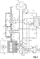
- FIG. 1 shows a schematic representation of combined heat and power plant preferential embodiment with incorporated water source high temperature heat pump (HP) having a condenser and evaporator unit for heat pump principle utilization, where following items are shown and marked: cogeneration unit (CHP) with prime mover, preferably internal combustion engine (ICE) with adapted electrical generator (G), heat distribution circuit comprising a network of pipes (P1 - P19), valves (V1 - V3) and pumps (PU1 - PU4) which interconnects the heat consumer (HC) with heat sources, heat exchangers (HE1 - HE3), hatches (H1 - H4), fan (F1), external cooling system (CT1), ambient (O) and control temperature sensors (T1-T13).
- cogeneration unit with prime mover, preferably internal combustion engine (ICE) with adapted electrical generator (G)
- heat distribution circuit comprising a network of pipes (P1 - P19), valves (V1 - V3) and pumps (PU1 - PU4) which interconnect
- the system comprises an internal combustion engine (ICE), preferably a water cooled gas engine, which runs on a gas fuel, such as natural gas, liquefied petroleum gas, landfill gas, wood gas or biogas for example.
- ICE internal combustion engine
- generator G
- flue gas lubrication oil, charging air and exhaust gas, hereinafter addressed as flue gas
- the main heat source for heat consumer is preferably represented by internal combustion engine (ICE) cooling system (i.e. a jacket type heat exchanger, having an inlet and outlet aperture, herein addressed as inflow and outflow aperture) whereby plurality of waste heat sources arise in the scope of the cogeneration unit (CHP) and incorporated heat pump (HP) when the internal combustion engine (ICE) and heat pump (HP) are turned on and powered, preferably at optimum efficiency or full load regime.
- ICE internal combustion engine
- HP heat pump
- first and most important waste heat source is represented by flue gas in exhaust system, which is a product of the combustion process within the internal combustion engine (ICE).
- ICE internal combustion engine
- HP heat pump
- lubrication oil cooling system i.e. incorporated compressors lubrication oil cooling system
- the internal combustion engine (ICE) cooling system inflow and outflow apertures are operably coupled to the heat distribution circuit comprising a network of pipes (P1 - P19) that operably interconnects the heat consumer (HC) with heat sources in the scope of cogeneration plant with incorporated water source high temperature heat pump (HP).
- the heat distribution circuit further comprises a primary heat transfer medium and automated regulation means comprising the control unit (i.e. control electronics), valves (V1 - V3) and pumps (PU1 - PU4) for primary heat transfer medium flow regulation, wherein the heat of heat sources is preferably transferred to the heat consumer (HC) by principle of primary heat transfer medium circulation in a closed loop heat distribution circuit.
- the waste heat of flue gas is utilized by incorporated heat exchanger (HE1) which collects the high temperature waste heat of flue gas in exhaust system, wherein the exhaust heat exchanger (HE1) is capable to collect the waste heat due to the significant temperature difference between the flue gas in exhaust system and primary heat transfer medium in incorporated heat exchanger (HE1).
- exhaust system according to the invention preferably comprises at least one additional condensing heat exchanger (HE2), which is incorporated to collect at least the residual low temperature waste heat of flue gas, being used afterwards by water source high temperature heat pump (HP) to enhance the heating power of the cogeneration unit (CHP).
- the depicted embodiment comprises two heat exchangers (HE1, HE2) incorporated into the internal combustion engine (ICE) exhaust system with aim to collect the waste heat of combustion process, wherein it is important to notice, that the first heat exchanger (HE1) is operably coupled to the forward line of heat distribution circuit, wherein the flow of primary heat transfer medium through the heat exchanger (HE1) cools down the temperature of flue gas to approximately 120°C; and furthermore, the second (i.e.
- HE2 condensing heat exchanger
- HP high temperature heat pump
- evaporator unit preferably in a closed loop piping system with secondary heat transfer medium involved
- the temperature of the flue gas in exhaust system is additionally reduced to the temperature close to the ambient (O), preferably bellow 25°C.
- the exhaust system may further comprise a suction fan (F1) for removal of flue gas from exhaust system, if necessary.
- the heating power of represented cogeneration unit can be furthermore enhanced if the first heat exchanger (HE1) is partially or completely bypassed by means of flue gas stream manipulation (i.e. regulation) means comprising motorized valves, preferably hatches (H1-H4), regulated by said control unit.
- flue gas stream manipulation i.e. regulation
- the heat exchanger (HE2) and heat pump (HP) shall be implemented in a multistage approach or cascade principle comprising a plurality of heat pumps (HP) and/or heat exchangers (HE2) in parallel and/or serial connection, to reach the simplified and cost effective solution for exhaust system as well.
- the waste heat of internal combustion engine charging air or lubrication oil cooling system can be collected as well by at least one additional heat exchanger (HE3), which is operably coupled to the heat pump (HP) evaporator unit in serial or parallel connection with above described heat exchanger (HE2) in exhaust system, wherein the lubrication oil cooling system of heat pump (HP) compressor is preferably incorporated into the water source high temperature heat pump (HP) enclosure.
- HE3 heat pump (HP) evaporator unit in serial or parallel connection with above described heat exchanger (HE2) in exhaust system
- HP heat pump
- HP water source high temperature heat pump
- water source high temperature heat pump (HP) utilization uses at least one low temperature waste heat source for vaporization of working medium of incorporated heat pump (HP), wherein the condenser unit outlet is preferably fed to the heat distribution circuit return line, more precisely to the inflow of the internal combustion engine (ICE) cooling system, where the aim of proposed inventive approach is to reach and maintain the maximum allowed temperature of the primary heat transfer medium at the inlet of the engine cooling system.
- HP water source high temperature heat pump
- the heat distribution circuit comprises a cooling system bypass connection, hence the cooling system is at least partially bypassed when the maximum allowed temperature of primary heat transfer medium at inflow aperture of the internal combustion engine (ICE) cooling system is reached and successfully maintained at defined set point with hysteresis, wherein the valve (V1) is reconfigured by automated regulation means to a position, which at least partially redirects the primary heat transfer medium stream from condenser unit outlet to the forward line of heat distribution circuit.
- the heat distribution circuit further comprises a heat pump (HP) condenser unit bypass connection, wherein the condenser unit is at least partially bypassed according to the heat demand situation in heat distribution circuit.
- HP heat pump
- the invention relates to a method of the heat pump (HP) integration process, to a method for utilization of low grade temperature waste heat sources of cogeneration unit (CHP) by water source high temperature heat pump (HP) and to a method of using the apparatus according to the invention.
- HP heat pump
- combustion process is substantially a continuous process
- said internal combustion engine normally operates in the range between its minimum and maximum rated operating power, preferably at normal rated power in continuous operation.
- the liquid-vapor phase change thermodynamic cycle utilization process is substantially a continuous process, wherein said heat pump (HP) operates in the range between its minimum and maximum rated operating power, preferably at normal rated power in continuous operation.
- the fuel combustion process in complex i.e.
- ICE internal combustion engine
- HP heat pump
- the thermal energy balance adjustment is executed by adapting the power of said heat pump (HP) and/or by adapting the power of said internal combustion engine (ICE) and/or by adapting the mass flow of the primary heat transfer medium through the engine cooling system of said internal combustion engine and/or by adapting the mass flow of the primary heat transfer medium through the heat pump (HP) and/or by adapting the mass flow of the secondary heat transfer medium in at least one of said closed loop circuit for waste heat source utilization.
- the mass flow of the primary heat transfer medium in said heat distribution circuit is adapted by changing the flow velocity in said heat distribution circuit and/or the mass flow of the secondary heat transfer medium in said closed loop circuit is adapted by changing the flow velocity in said closed loop circuit, wherein the velocity of heat transfer medium in heat distribution network is adapted by switching (i.e. on/off regulation) and/or by adjusting the power of at least one circulation pump for mass flow adjustment.
- the mass flow of the primary heat transfer medium in said heat distribution circuit is alternatively adapted by stream flow regulation, wherein at least a portion of the primary heat transfer medium stream in the return line of said heat distribution circuit is redirected to the return line of said heat distribution circuit to provide a heat pump (HP) bypass connection, and/or wherein at least a portion of the primary heat transfer medium stream from said heat pump (HP) is redirected to a forward line of the heat distribution circuit to provide an engine cooling system bypass connection.
- the mass flow of the secondary heat transfer medium in said closed loop circuit for waste heat source utilization is adapted by stream flow regulation, wherein at least a portion of the secondary heat transfer medium stream is redirected in said closed loop circuit to provide a bypass connection for at least one waste heat recovery unit.
- the mass flow regulation of the primary heat transfer medium and/or the mass flow regulation of the secondary heat transfer medium for thermal energy balance adjustment is determined, controlled and executed by at least one control unit (i.e. electronic controller), wherein the position and/or the state (i.e. open/closed or on/off regulation) of the automated regulation means is adjusted in respect to the heat demand in said heat distribution network.
- control unit i.e. electronic controller
- the apparatus according to the invention may further comprise at least one control unit, wherein such a controller shall be autonomous device for thermal management regulation or alternatively, at least basic functions of the thermal management controller for determination process, comparison process and execution process could be incorporated and implemented to the internal combustion engine (ICE) controller or in to the heat pump (HP) controller as well.
- ICE internal combustion engine
- HP heat pump
- the environment and thermal conditions of heat distribution network is determined by the group of thermal, pressure or other sensors, wherein at least one input from at least one sensor of heat distribution network or internal combustion engine (ICE) is used for comparison process, where at least one value of at least one input parameter (i.e. preferably a temperature of the primary heat transfer medium in engine cooling system) is analyzed and compared to the limiting values, preferably being pre-defined and stored in the control unit.
- ICE internal combustion engine
- the execution process comprises a process of executing instructions stored in control unit to generate appropriate output signal, where at least one parameter for thermal energy balance adjustment is generated, executed and performed by control electronics in cooperation with automated regulation means in order to reach and maintain the threshold set-point value, wherein said threshold value is defined between the maximum value and the minimum value for set point equal value with aim to provide a hysteresis for thermal energy balance adjustment.
- control unit i.e. electronic module
- control unit may communicate with various output devices where the temperature of the heat transfer medium in the heat transfer network is determined, controlled and regulated by a group of automated regulation means comprising motorized valves, pumps and sensors, wherein regulation means are preferably adapted to be manipulated by at least one control unit.
- the heat distribution process in heat distribution network is provided by at least one heat transfer medium, preferably by plurality of heat distribution mediums.
- the heat in said heat transfer network is transferred from first heat releasing unit to the heat consumer (HC) by circulation of the primary heat transfer medium in at least one closed loop circuit, and similarly the heat from waste heat recovery unit is transferred to the heat pump (HP) by circulation of the secondary heat transfer medium in at least one closed loop circuit, wherein the heat upgraded by at least one heat pump (HP) is furthermore transferred from heat pump (HP) condenser unit to the engine cooling system of at least one internal combustion engine (ICE) by said primary heat transfer medium.
- the cooling circuits of cogeneration unit are used for utilization of water source high temperature heat pump (HP), wherein its hot water output is preferably used for establishing and maintaining the highest possible or maximum allowed temperature of primary heat transfer medium for internal combustion engine (ICE) cooling system inflow (i.e. cooling jacket inlet).
- HP water source high temperature heat pump
- ICE internal combustion engine
- all vital components of heat distribution circuit are preferably operably coupled for heat transfer medium circulation, wherein the compressor of the incorporated heat pump (HP) shall be driven by electric machine, powered by electricity from grid or generator (G), or alternatively if appropriate, a high temperature heat pumps (HP) compressor shall be mechanically coupled to and driven by internal combustion engine (ICE) as well.
- the primary heat transfer medium in preferential embodiment is water and similarly, the secondary heat transfer medium in preferential embodiment is mix of water and glycol.
Landscapes
- Engineering & Computer Science (AREA)
- Chemical & Material Sciences (AREA)
- Combustion & Propulsion (AREA)
- Mechanical Engineering (AREA)
- General Engineering & Computer Science (AREA)
- Physics & Mathematics (AREA)
- Thermal Sciences (AREA)
- Heat-Pump Type And Storage Water Heaters (AREA)
- Engine Equipment That Uses Special Cycles (AREA)
Claims (12)
- Verfahren zur Verwendung einer Wärme- und Stromerzeugungsvorrichtung zum Erwärmen mindestens eines Wärmeverbrauchers (HC) in einem Wärmeverteilungsnetz durch Anwenden eines Prinzips einer Hochtemperaturwärmepumpen (HP) Quellquelle für die Verwendung einer Abwärmequelle, das Verfahren bestehend aus:einen Brennstoffverbrennungsprozess, bei dem ein Motorkühlsystem mindestens eines Verbrennungsmotors (ICE) verwendet wird, um eine erste Wärmeabgabeeinheit zum Erwärmen mindestens eines Wärmeübertragungsmediums in dem Wärmeverteilungsnetz bereitzustellen, und wobei mindestens eine Abwärmequelle vorhanden ist entstehen, wenn der Verbrennungsmotor (ICE) eingeschaltet wird und läuft, indem der Kraftstoff im Verbrennungsprozess gezündet wird;ein Abwärmerückgewinnungsverfahren, bei dem mindestens eine Abwärmerückgewinnungseinheit verwendet wird, um mindestens einen Teil der Wärme mindestens einer Abwärmequelle aus einer Gruppe von Abwärmequellen zu sammeln, die ein Dimgas in dem Abgassystem umfassen, wobei Luft beim Laden geladen wird Luftkühlsystem oder Schmieröl in einem Schmierölkühlsystem;und einen thermodynamischen Zyklus mit Phasenveränderung in Form eines Flüssigdampfphasenwechsels, wobei mindestens eine Hochtemperaturwärmepumpe (HP) mit Wasserquelle verwendet wird, um eine zweite Wärmefreisetzungseinheit zum Erwärmen mindestens eines Wärmeübertragungsmediums in dem Wärmeverteilungsnetzwerk bereitzustellen, wenn die Wärmepumpe ist (HP) ist eingeschaltet und in BetriebDie für den Flüssigdampfphasenwechselzyklus erforderliche Wärme wird vollständig oder teilweise durch den Abwärmerückgewinnungsprozess erhalten, wobei mindestens ein Teil der im Prozesswiederherstellungsprozess gesammelten Wärme für den thermodynamischen Flüssigdampfphasenzyklus verwendet wird Prozessnutzung, und wobei mindestens ein Teil der von mindestens einer Wärmepumpe (HP) in der zweiten Wärmetauschereinheit erzeugten Wärme zum Heizen eines Kühlsystems des Motors von mindestens einem Motor mit Verbrennungsmotor (ICE) in der ersten Wärme verwendet wird Freigabeeinheit;die Wärme in dem mindestens einen geschlossenen Kreislauf des Wärmeverteilungsnetzes wird vorzugsweise durch Zirkulation von mindestens einem Wärmeträgermedium verteilt, wobei die niedrigste Temperatur des Wärmeverteilungsmediums in dem Motorkühlsystem mindestens eines Verbrennungsmotors (ICE) liegt) und die erste Wärmefreisetzungseinheit wesentlich höher ist als die niedrigste Temperatur des Wärmeverteilungsmediums in mindestens einem Wärmeverbraucher (HC) im Wärmeverteilungsnetz, dadurch gekennzeichnet, dassmindestens ein Wärmeträgermedium in mindestens einer Rückführleitung des Wärmeverteilungsnetzes wird durch das Prinzip der Wärmepumpe (HP) erneut erhitzt, wobei die Temperatur des Wärmeträgermediums in dem Motorkühlsystem mindestens eines Verbrennungsmotors ist (ICE) ist wesentlich höher als 60°C, zumindest wenn eine Auslegungstemperatur des Wärmeverteilungsnetzes erreicht ist und der Verbrennungsmotor (ICE) und die Wärmepumpe (HP) bei Volllast arbeiten.
- Verfahren nach Anspruch 1, dadurch gekennzeichnet
der Kraftstoffverbrennungsprozess ist ein im Wesentlichen kontinuierlicher Prozess, wobei der Verbrennungsmotor (ICE) im Bereich zwischen seiner minimalen und maximalen Nennbetriebsleistung arbeitet, vorzugsweise bei normaler Nennleistung im Dauerbetrieb;
der thermodynamische Zyklus der Phase-Phase-Änderung der Flüssigphasenänderung ist im Wesentlichen ein kontinuierlicher Prozess, wobei die Wärmepumpe (HP) im Bereich zwischen ihrer minimalen und maximalen Nennbetriebsleistung arbeitet, vorzugsweise bei normaler Nennleistung im Dauerbetrieb;
Der Abwärmerückgewinnungsprozess umfasst einen Prozess der Rauchgaskondensation, wobei die gesammelte Wärme für das Prinzip der Wärmepumpe (HP) verwendet wird und die Temperatur des Dimgases unter 25°C verringert wird, daher ist das Dimgas im Abgassystem durch Belüften des Abgassystems durch einen eingebauten Lüfter (F1) entfernt werden;
der Abwärmerückgewinnungsprozess wird zur Verwendung des Kühlprinzips verwendet, wobei der Wärmerückgewinnungsprozess zum Kühlen der Ladeluft für die Brennstoffverbrennungsprozessverwendung verwendet wird;
Die Temperatur des Wärmeübertragungsmediums in dem Wärmeübertragungsnetzwerk wird durch eine Gruppe automatisierter Regulierungsmittel bestimmt, gesteuert und gesteuert, die ein Ventil (V1 - V3), eine Pumpe (PU1 - PU4) und einen Sensor (T1 - T13) umfassen, wobei die Regelung erfolgt Mittel sind vorzugsweise dazu eingerichtet, von mindestens einer Steuereinheit manipuliert zu werden. - Verfahren nach Anspruch 2, dadurch gekennzeichnet
Der Kraftstoffverbrennungsprozess wird durch eine Vielzahl von Verbrennungsmotor (ICE) Einheiten bereitgestellt, wobei die Wärme in der ersten Wärmefreisetzungseinheit in einer seriellen und / oder parallelen Verbindung übertragen wird, um Wärme zwischen den Kühlsystemen des Motors zu übertragen, um einen ersten bereitzustellen Wärmefreisetzungseinheit;
Der thermodynamische Kreislauf-Phasenwechsel-Prozess wird durch eine Vielzahl von Wärmepumpeneinheiten (HP) bereitgestellt, wobei die Wärme in der zweiten Wärmefreisetzungseinheit in einer seriellen und / oder parallelen Verbindung übertragen wird, um die Wärme zwischen der Wärmepumpe (HP) zu übertragen. Einheiten, um die zweite Wärmeabgabeeinheit bereitzustellen;
Der Wärmeverteilungsprozess in dem Wärmeverteilungsnetzwerk wird durch eine Vielzahl von Wärmeverteilungsmedien bereitgestellt, wobei die Wärme in dem Wärmeaustauschnetzwerk von der ersten Wärmefreisetzungseinheit zu dem Wärmeverbraucher (HC) durch Zirkulation des primären Wärmeaustauschmediums in mindestens einem übertragen wird einen geschlossenen Kreislauf, bei dem die Wärme von der Abwärmerückgewinnungseinheit durch Zirkulation des sekundären Wärmeübertragungsmediums in mindestens einem geschlossenen Kreislauf zu der Wärmepumpe (HP) übertragen wird, und wobei die Wärme durch mindestens eine Wärmepumpe (HP) aufgewertet wird ferner durch das primäre Wärmeträgermedium auf ein Motorkühlsystem mindestens eines Verbrennungsmotors (ICE) übertragen. - Verfahren nach Anspruch 3, dadurch gekennzeichnet
die Temperatur des primären Wärmeübertragungsmediums in dem Motorkühlsystem des Verbrennungsmotors (ICE) wird auf einem vorbestimmten Sollwert gehalten, wobei die Anpassung des thermischen Energieausgleichs durch Anpassen der Leistung der Wärmepumpe (HP) und / oder durchgeführt wird durch Anpassen der Leistung des Verbrennungsmotors (ICE) und / oder durch Anpassen des Massenstroms des primären Wärmeträgermediums durch das Motorkühlsystem des Verbrennungsmotors und / oder durch Anpassen des Massenstroms des primären Wärmeträgermediums durch die Wärmepumpe (HP) und / oder durch Anpassen des Massenstroms des sekundären Wärmeübertragungsmediums in dem geschlossenen Kreislauf zur Nutzung der Abwärmequelle. - Verfahren nach Anspruch 4, dadurch gekennzeichnet
der Massenstrom des primären Wärmeübertragungsmediums in dem Wärmeverteilungskreislauf wird angepasst, indem die Strömungsgeschwindigkeit in dem Wärmeverteilungskreislauf geändert wird und / oder der Massenstrom des sekundären Wärmeübertragungsmediums in dem geschlossenen Kreislaufkreislauf durch Ändern der Strömungsrate angepasst wird in dem geschlossenen Kreislauf, wobei die Geschwindigkeit des Wärmeträgermediums in dem Wärmeverteilungsnetzwerk durch Schalten und / oder durch Einstellen der Leistung von mindestens einer Umwälzpumpe angepasst wird. - Verfahren nach Anspruch 4, dadurch gekennzeichnet
der Massenstrom des primären Wärmeübertragungsmediums in dem Wärmeverteilungskreislauf wird durch Stromflussregulierung angepasst, wobei mindestens ein Teil des Primärstrom-Mediumübertragungsmediums in der Rückführleitung des Wärmeverteilungskreislaufs zu der Rückführleitung des Wärmeleitungskreislaufs geleitet wird (HP) Bypass-Verbindung, und / oder wobei mindestens ein Teil des primären Wärmeübertragungsmediumstroms von der Wärmepumpe (HP) zur Vorwärtsleitung des Wärmeverteilungskreislaufs umgeleitet wird, um eine Bypass-Anschluss des Motorkühlsystems;
Der Massenstrom des sekundären Wärmetransfermediums in dem geschlossenen Kreislauf zur Abwärmenutzung wird durch Stromflussregulierung angepasst, wobei mindestens ein Teil des sekundären Wärmeträgermediums in dem geschlossenen Kreislauf umgeleitet wird, um eine Bypass-Verbindung bereitzustellen für mindestens eine Abwärmerückgewinnungseinheit. - Verfahren nach Anspruch 5 und 6, dadurch gekennzeichnet
die Massenstromregelung des primären Wärmeträgermediums und / oder die Massenstromregelung des sekundären Wärmeträgermediums zur Einstellung der thermischen Energiebilanz wird von dieser Steuereinheit bestimmt, gesteuert und ausgeführt, wobei die Position und / oder der Zustand des automatisierten Regulierungsmittel werden in Bezug auf den Wärmebedarf in dem Wärmeverteilungsnetz eingestellt. - Vorrichtungsanordnung für eine Wärmeerzeugungsanlage-Abwärmequelle, umfassend:wobei das Motorkühlsystem ferner mindestens eine Einlassöffnung und mindestens eine Ausströmöffnung umfasst, wobei der mindestens eine Verbrennungsmotor (ICE) ferner ein Motorkühlsystem, ein Abgassystem, ein Schmierölkühlsystem und ein Ladeluftkühlsystem umfasst;wobei die Wärmepumpe (HP) ferner ein Schmierölkühlsystem, eine Verdampfereinheit und eine Kondensatoreinheit umfasst, und wobei die Kondensatoreinheit ferner eine Einlassöffnung und eine Auslassöffnung umfasst;und mindestens eine Abwärmerückgewinnungseinheit, vorzugsweise einen Wärmetauscher (HE2), der dazu eingerichtet ist, der Verdampfereinheit in einem geschlossenen Kreislauf zugeordnet zu werden;wobei die Abwärmerückgewinnungseinheit dazu eingerichtet ist, mit mindestens einer der Gruppe von Abwärmequellen verbunden zu werden, die ein Abgassystem, ein Schmierölkühlsystem und ein Ladeluftkühlsystem zum Sammeln von Wärme der Abwärmequelle umfasst; undwobei die Verdampfereinheit dazu eingerichtet ist, der Abwärmerückgewinnungseinheit in einem geschlossenen Kreislauf zugeordnet zu werden, um die gesammelte Wärme von der Abwärmerückgewinnungseinheit zu der Verdampfereinheit durch ein sekundäres Wärmeübertragungsmedium in dem geschlossenen Kreislauf zu übertragen; dadurch gekennzeichnetder Auslass der Kondensoreinheit dazu eingerichtet ist, mit dem Einlass des Motorkühlsystems verbunden zu werden, um die Wärme der Kondensoreinheit durch ein primäres Wärmeträgermedium in einem Wärmeverteilungskreislauf an das Motorkühlsystem zu übertragen; undder Einlass der Kondensoreinheit und der Ausfluss des Motorkühlsystems sind so ausgebildet, dass sie dem Wärmeverteilungskreislauf zugeordnet werden können, wobei der Wärmeverteilungskreis ferner mindestens eine Aufnahmeeinheit für Wärmeenergie umfasst, vorzugsweise einen Wärmeverbraucher (HC).
- Geräteanordnung für die BHKW-Abwärmenutzung nach Anspruch 8, dadurch gekennzeichnet, dass
wobei die Vorlaufleitung und die Rücklaufleitung den Abfluss des Motorkühlsystems und den Einlass der Kondensatoreinheit über mindestens einen Wärmeverbraucher (HC) miteinander verbinden, wobei der Wärmeleitungskreis mindestens eine Vorlaufleitung und mindestens eine Rücklaufleitung umfasst, das primäre Wärmeübertragungsmedium in dem Wärmeverteilungskreislauf zirkuliert, um die Wärme der Wärmequelle an den Wärmeverbraucher (HC) zu übertragen;
der Ausfluss des Motorkühlsystems ist betriebsmäßig mit der Vorwärtsleitung des Wärmeverteilungskreises gekoppelt;
der Einlass der Kondensatoreinheit betriebsmäßig mit mindestens einer Rückführleitung des Wärmeverteilungskreises gekoppelt ist;
der Auslass der Kondensatoreinheit betriebsmäßig mit dem Einlass des Motorkühlsystems gekoppelt ist, wobei der Wärmeverteilungskreis ein primäres Wärmeübertragungsmedium umfasst; und
wobei der Wärmetauscher (HE2) in das Abgassystem eingebaut ist, um mindestens einen Teil der Wärme des Abgases aufzunehmen, wobei der Wärmetauscher (HE2) betriebsmäßig mit der Verdampfereinheit in einem geschlossenen Kreislauf verbunden ist, der ein sekundäres Wärmeübertragungsmedium umfasst, wobei die im Wärmetauscher (HE2) gesammelte Wärme durch die Zirkulation des sekundären Wärmeträgermediums in dem geschlossenen Kreislauf zu der Verdampfereinheit übertragen wird, und ferner die Wärme der Kondensatoreinheit durch ein primäres Wärmeträgermedium an das Motorkühlsystem übertragen wird Zirkulation in dem Kopfverteilungskreislauf, wobei die Temperatur des primären Wärmeübertragungsmediums am Einlass des Motorkühlsystems wesentlich höher als 60°C ist, wenn der Verbrennungsmotor (ICE) und die Wärmepumpe (HP) eingeschaltet und mit Energie versorgt werden Betriebsbedingungen. - Geräteanordnung für die BHKW-Abwärmenutzung nach Anspruch 8, dadurch gekennzeichnet, dass
der geschlossene Kreislauf ferner einen zusätzlichen Wärmetauscher (HE3) umfasst, wobei der zusätzliche Wärmetauscher (HE3) dazu eingerichtet ist, einem externen Kühlsystem (CT1) zugeordnet zu werden, wobei das externe Kühlsystem (CT1) einem a zugeordnet werden kann Schmierölkühlsystem für Verbrennungsmotor (ICE), Schmierölkühlsystem für Wärmepumpe (HP) und / oder Ladeluftkühlsystem für Verbrennungsmotor (ICE). - Geräteanordnung für die Abwärmenutzung von BHKW nach Anspruch 9 und 10, dadurch gekennzeichnet, dass
der Wärmeverteilungskreis eine Vielzahl von Wärmeverbrauchern (HC) in Parallelschaltung und / oder in Reihenschaltung aufweist;
der Wärmeverteilungskreislauf eine Vielzahl von Wärmepumpen (HP) in einer Parallelschaltung und / oder in einer Reihenschaltung umfasst, wobei der geschlossene Kreislauf der Verdampfereinheit eine Vielzahl von Wärmetauschern (HE2, HE3) in einer Parallelschaltung und / oder in umfasst serielle Verbindung, und wobei mindestens eine der Auslassöffnungen der Kondensatoreinheit betriebsmäßig mit dem Einlass des Verbrennungsmotorkühlsystems (ICE) gekoppelt ist. - Geräteanordnung für die BHKW-Abwärmenutzung nach Anspruch 11, dadurch gekennzeichnet, dass
wobei der Verbrennungsmotor (ICE) als ein gasbetriebener Motor ausgebildet ist, der mit einem Gaskraftstoff betrieben wird, der aus einer Gruppe ausgewählt wird, die ein Erdgas, ein Flüssiggas, ein Deponiegas, ein Holzgas oder ein Biogas umfasst, wobei das Motorkühlsystem als Motor ausgebildet ist Mantelkühlsystem des Verbrennungsmotors (ICE); das primäre Wärmeübertragungsmedium in der bevorzugten Ausführungsform ist Wasser; das sekundäre Wärmeträgermedium ist in einer bevorzugten Ausführungsform eine Mischung aus Wasser und Glykol; und mindestens einer der Wärmetauscher (HE2) als Kondensationswärmetauscher (HE2) ausgebildet ist, wobei das Abgassystem ferner mindestens einen Lüfter (F1) zur Gasabsaugung umfasst.
Applications Claiming Priority (2)
| Application Number | Priority Date | Filing Date | Title |
|---|---|---|---|
| SI201400339A SI24856A (sl) | 2014-10-03 | 2014-10-03 | Metoda in naprava za izrabo nizkotemperaturnih virov kogeneracijskih sistemov z visokotemperaturno toplotno črpalko po konceptu voda/voda |
| PCT/IB2015/001617 WO2016051246A1 (en) | 2014-10-03 | 2015-09-14 | Method and apparatus for cogeneration power plant waste heat source utilization by incorporated water source high temperature heat pump |
Publications (2)
| Publication Number | Publication Date |
|---|---|
| EP3201532A1 EP3201532A1 (de) | 2017-08-09 |
| EP3201532B1 true EP3201532B1 (de) | 2019-01-09 |
Family
ID=54330804
Family Applications (1)
| Application Number | Title | Priority Date | Filing Date |
|---|---|---|---|
| EP15781715.6A Not-in-force EP3201532B1 (de) | 2014-10-03 | 2015-09-14 | Verfahren und vorrichtung zur heizkraftwerkabwärmequellennutzung durch integrierte wasserquellenhochtemperaturwärmepumpe |
Country Status (8)
| Country | Link |
|---|---|
| US (1) | US20170298866A1 (de) |
| EP (1) | EP3201532B1 (de) |
| JP (1) | JP2017531764A (de) |
| CN (1) | CN107003012A (de) |
| CA (1) | CA2963336A1 (de) |
| DK (1) | DK3201532T3 (de) |
| SI (1) | SI24856A (de) |
| WO (1) | WO2016051246A1 (de) |
Families Citing this family (17)
| Publication number | Priority date | Publication date | Assignee | Title |
|---|---|---|---|---|
| ITUA20164791A1 (it) * | 2016-06-30 | 2017-12-30 | Metan Alpi Sestriere Teleriscaldamento S R L | Sistema e procedimento per il recupero di calore da fumi di combustione, in particolare in una centrale per la produzione di energia elettrica, e relativo procedimento di regolazione. |
| GB2559114A (en) * | 2016-12-20 | 2018-08-01 | Encora Tech Limited | A dynamically adaptive combined heat and power system and method thereof |
| DE102017202227A1 (de) * | 2017-02-13 | 2018-08-16 | Siemens Aktiengesellschaft | Verfahren zum Betrieb einer Wärmepumpenanlage, Wärmepumpenanlage und Kraftwerk mit einer Wärmepumpenanlage |
| EP3593044B1 (de) * | 2017-03-07 | 2023-09-06 | Carbon Cap Inc. | Rauchgasenergierückgewinnungssystem |
| CN108930996B (zh) * | 2017-05-22 | 2024-03-26 | 山西三合盛智慧科技股份有限公司 | 一种能量梯级利用的多能互补供热系统及供热方法 |
| EP3505831A1 (de) * | 2017-12-27 | 2019-07-03 | Brunnshög Energi AB | Steuereinheit und verfahren zur steuerung der wärme- oder kälteentnahme eines lokalen verteilungssystems aus einem thermischen energieverteilungsnetz |
| US11592215B2 (en) | 2018-08-29 | 2023-02-28 | Waterfurnace International, Inc. | Integrated demand water heating using a capacity modulated heat pump with desuperheater |
| IT201900006975A1 (it) * | 2019-05-17 | 2020-11-17 | Bb Eng S R L S Unipersonale | Impianto di cogenerazione migliorato |
| EP3879187A1 (de) | 2020-03-12 | 2021-09-15 | E.ON Sverige AB | Verbesserter wirkungsgrad für ein wärmeextraktionssystem und/oder ein wärmeabgabesystem |
| CA3194712A1 (en) | 2020-10-07 | 2022-04-14 | Michael SCHILDT | Micro-combined heat and power system with exterior generator and heating system compatibility and method of use |
| JP7522073B2 (ja) * | 2021-05-24 | 2024-07-24 | 株式会社荏原製作所 | サブファブエリア設置装置 |
| CN114754402A (zh) * | 2022-04-22 | 2022-07-15 | 付春水 | 一种用于高寒地区污水处理厂热电联产系统 |
| CN115218252B (zh) * | 2022-07-11 | 2023-03-21 | 朴瑞(北京)企业管理有限公司 | 用于城市节能供热的智能高效换热系统 |
| US12116908B2 (en) * | 2022-08-17 | 2024-10-15 | Innio Waukesha Gas Engines Inc. | System for utilizing a thermomechanical cycle to drive a compressor |
| CN116163852B (zh) * | 2022-12-10 | 2025-05-13 | 中国重汽集团济南动力有限公司 | 一种卡车上的有机朗肯循环余热回收系统 |
| CN116398924B (zh) * | 2023-04-11 | 2025-10-28 | 济南市市政工程设计研究院(集团)有限责任公司 | 一种炭素厂工业余热利用供热系统 |
| KR20260091306A (ko) * | 2024-12-10 | 2026-06-17 | 주식회사 파나시아 | 폐열을 이용한 전력 생산 시스템 |
Family Cites Families (15)
| Publication number | Priority date | Publication date | Assignee | Title |
|---|---|---|---|---|
| JPS5852949A (ja) * | 1981-09-24 | 1983-03-29 | 株式会社東芝 | エンジン駆動ヒ−トポンプ装置 |
| DE3206967A1 (de) * | 1982-02-26 | 1983-09-08 | Bedia Maschinenfabrik Verwaltungs-GmbH, 5300 Bonn | Durch eine verbrennungskraftmaschine angetriebene waermepumpe |
| DE3912113A1 (de) * | 1989-04-13 | 1989-12-07 | Ekkehard Dipl Ing Bretting | Erweitertes blockheizkraftwerk (bhkw) mit waermepumpe zur restwaermeintegration |
| JP2000064906A (ja) * | 1998-08-18 | 2000-03-03 | Denso Corp | エンジン駆動式ヒートポンプサイクル |
| JP3871193B2 (ja) * | 2001-07-03 | 2007-01-24 | 本田技研工業株式会社 | エンジンの排熱回収装置 |
| KR100579576B1 (ko) | 2004-08-17 | 2006-05-15 | 엘지전자 주식회사 | 열병합 발전 시스템 |
| JP4197005B2 (ja) * | 2006-05-15 | 2008-12-17 | トヨタ自動車株式会社 | 排気熱回収装置 |
| CH701785A1 (de) | 2009-09-07 | 2011-03-15 | Walter Schmid | Anlage zur Bereitstellung von Wärmeenergie. |
| JP5594645B2 (ja) * | 2010-07-08 | 2014-09-24 | 三浦工業株式会社 | 蒸気システム |
| AT15812U1 (de) * | 2011-05-17 | 2018-07-15 | Walter Hauptmann Ddr | Effizienzoptimierte wärmepumpenanlage |
| CH705372B1 (de) * | 2011-08-02 | 2015-06-15 | Ws Projektentwicklungs Ag | Kompaktanlage zur Bereitstellung von Wärmeenergie an einen Verbraucher mit einem Heizsystem. |
| JP5845161B2 (ja) * | 2012-10-16 | 2016-01-20 | 本田技研工業株式会社 | コージェネレーション装置 |
| RU2523243C1 (ru) * | 2012-12-03 | 2014-07-20 | Ильдус Юнусович Абдуллин | Установка для отопления и/или горячего водоснабжения |
| JP2014173742A (ja) * | 2013-03-06 | 2014-09-22 | Miura Co Ltd | 給水加温システム |
| CN103334820B (zh) * | 2013-07-15 | 2015-06-10 | 西华大学 | 一种汽车发动机的热控制系统及热控制方法 |
-
2014
- 2014-10-03 SI SI201400339A patent/SI24856A/sl not_active IP Right Cessation
-
2015
- 2015-09-14 CA CA2963336A patent/CA2963336A1/en not_active Abandoned
- 2015-09-14 JP JP2017537027A patent/JP2017531764A/ja active Pending
- 2015-09-14 US US15/516,413 patent/US20170298866A1/en not_active Abandoned
- 2015-09-14 WO PCT/IB2015/001617 patent/WO2016051246A1/en not_active Ceased
- 2015-09-14 DK DK15781715.6T patent/DK3201532T3/en active
- 2015-09-14 CN CN201580062401.2A patent/CN107003012A/zh active Pending
- 2015-09-14 EP EP15781715.6A patent/EP3201532B1/de not_active Not-in-force
Non-Patent Citations (1)
| Title |
|---|
| None * |
Also Published As
| Publication number | Publication date |
|---|---|
| DK3201532T3 (en) | 2019-04-01 |
| US20170298866A1 (en) | 2017-10-19 |
| JP2017531764A (ja) | 2017-10-26 |
| EP3201532A1 (de) | 2017-08-09 |
| WO2016051246A1 (en) | 2016-04-07 |
| SI24856A (sl) | 2016-04-29 |
| CA2963336A1 (en) | 2016-04-07 |
| CN107003012A (zh) | 2017-08-01 |
Similar Documents
| Publication | Publication Date | Title |
|---|---|---|
| DK3201532T3 (en) | METHOD AND DEVICE FOR UTILIZATION OF WASTE HEAT FROM CHANGE HEATERS BY INCORPORATED HIGH TEMPERATURE HEAT PUMP WITH WATER SOURCE | |
| US9840940B2 (en) | Multiple organic rankine cycle systems and methods | |
| US20180245800A1 (en) | Method and apparatus for utilization of hot water plant waste heat recovery by incorporated high temperature water source heat pump | |
| US8739541B2 (en) | System and method for cooling an expander | |
| WO2017191505A4 (en) | Method and apparatus for increasing the efficiency of the cogeneration power plant by the heat pump principle utilization for increasing the coolant inlet temperature | |
| US11378310B2 (en) | Dynamically adaptive combined heat and power system with a thermal energy store and method thereof | |
| CN103620167A (zh) | 废热利用设备 | |
| US9540961B2 (en) | Heat sources for thermal cycles | |
| RU2589985C2 (ru) | Способ работы рекуперационной установки | |
| JP2011169539A (ja) | 熱利用システム | |
| CZ27122U1 (cs) | Diferenční termodynamický modul |
Legal Events
| Date | Code | Title | Description |
|---|---|---|---|
| STAA | Information on the status of an ep patent application or granted ep patent |
Free format text: STATUS: THE INTERNATIONAL PUBLICATION HAS BEEN MADE |
|
| PUAI | Public reference made under article 153(3) epc to a published international application that has entered the european phase |
Free format text: ORIGINAL CODE: 0009012 |
|
| STAA | Information on the status of an ep patent application or granted ep patent |
Free format text: STATUS: REQUEST FOR EXAMINATION WAS MADE |
|
| 17P | Request for examination filed |
Effective date: 20170421 |
|
| AK | Designated contracting states |
Kind code of ref document: A1 Designated state(s): AL AT BE BG CH CY CZ DE DK EE ES FI FR GB GR HR HU IE IS IT LI LT LU LV MC MK MT NL NO PL PT RO RS SE SI SK SM TR |
|
| AX | Request for extension of the european patent |
Extension state: BA ME |
|
| DAV | Request for validation of the european patent (deleted) | ||
| DAX | Request for extension of the european patent (deleted) | ||
| STAA | Information on the status of an ep patent application or granted ep patent |
Free format text: STATUS: EXAMINATION IS IN PROGRESS |
|
| 17Q | First examination report despatched |
Effective date: 20180523 |
|
| GRAP | Despatch of communication of intention to grant a patent |
Free format text: ORIGINAL CODE: EPIDOSNIGR1 |
|
| STAA | Information on the status of an ep patent application or granted ep patent |
Free format text: STATUS: GRANT OF PATENT IS INTENDED |
|
| RIC1 | Information provided on ipc code assigned before grant |
Ipc: F02G 5/04 20060101ALI20180705BHEP Ipc: F24D 3/18 20060101AFI20180705BHEP Ipc: F01K 1/20 20060101ALI20180705BHEP Ipc: F01K 1/00 20060101ALI20180705BHEP Ipc: F24D 19/10 20060101ALI20180705BHEP |
|
| INTG | Intention to grant announced |
Effective date: 20180807 |
|
| GRAS | Grant fee paid |
Free format text: ORIGINAL CODE: EPIDOSNIGR3 |
|
| GRAA | (expected) grant |
Free format text: ORIGINAL CODE: 0009210 |
|
| STAA | Information on the status of an ep patent application or granted ep patent |
Free format text: STATUS: THE PATENT HAS BEEN GRANTED |
|
| AK | Designated contracting states |
Kind code of ref document: B1 Designated state(s): AL AT BE BG CH CY CZ DE DK EE ES FI FR GB GR HR HU IE IS IT LI LT LU LV MC MK MT NL NO PL PT RO RS SE SI SK SM TR |
|
| REG | Reference to a national code |
Ref country code: GB Ref legal event code: FG4D |
|
| REG | Reference to a national code |
Ref country code: CH Ref legal event code: EP Ref country code: AT Ref legal event code: REF Ref document number: 1087797 Country of ref document: AT Kind code of ref document: T Effective date: 20190115 |
|
| REG | Reference to a national code |
Ref country code: IE Ref legal event code: FG4D |
|
| REG | Reference to a national code |
Ref country code: DE Ref legal event code: R096 Ref document number: 602015023288 Country of ref document: DE |
|
| REG | Reference to a national code |
Ref country code: DK Ref legal event code: T3 Effective date: 20190325 |
|
| REG | Reference to a national code |
Ref country code: NL Ref legal event code: MP Effective date: 20190109 |
|
| REG | Reference to a national code |
Ref country code: LT Ref legal event code: MG4D |
|
| PG25 | Lapsed in a contracting state [announced via postgrant information from national office to epo] |
Ref country code: NL Free format text: LAPSE BECAUSE OF FAILURE TO SUBMIT A TRANSLATION OF THE DESCRIPTION OR TO PAY THE FEE WITHIN THE PRESCRIBED TIME-LIMIT Effective date: 20190109 |
|
| REG | Reference to a national code |
Ref country code: AT Ref legal event code: MK05 Ref document number: 1087797 Country of ref document: AT Kind code of ref document: T Effective date: 20190109 |
|
| PG25 | Lapsed in a contracting state [announced via postgrant information from national office to epo] |
Ref country code: PL Free format text: LAPSE BECAUSE OF FAILURE TO SUBMIT A TRANSLATION OF THE DESCRIPTION OR TO PAY THE FEE WITHIN THE PRESCRIBED TIME-LIMIT Effective date: 20190109 Ref country code: SE Free format text: LAPSE BECAUSE OF FAILURE TO SUBMIT A TRANSLATION OF THE DESCRIPTION OR TO PAY THE FEE WITHIN THE PRESCRIBED TIME-LIMIT Effective date: 20190109 Ref country code: FI Free format text: LAPSE BECAUSE OF FAILURE TO SUBMIT A TRANSLATION OF THE DESCRIPTION OR TO PAY THE FEE WITHIN THE PRESCRIBED TIME-LIMIT Effective date: 20190109 Ref country code: NO Free format text: LAPSE BECAUSE OF FAILURE TO SUBMIT A TRANSLATION OF THE DESCRIPTION OR TO PAY THE FEE WITHIN THE PRESCRIBED TIME-LIMIT Effective date: 20190409 Ref country code: PT Free format text: LAPSE BECAUSE OF FAILURE TO SUBMIT A TRANSLATION OF THE DESCRIPTION OR TO PAY THE FEE WITHIN THE PRESCRIBED TIME-LIMIT Effective date: 20190509 Ref country code: ES Free format text: LAPSE BECAUSE OF FAILURE TO SUBMIT A TRANSLATION OF THE DESCRIPTION OR TO PAY THE FEE WITHIN THE PRESCRIBED TIME-LIMIT Effective date: 20190109 Ref country code: LT Free format text: LAPSE BECAUSE OF FAILURE TO SUBMIT A TRANSLATION OF THE DESCRIPTION OR TO PAY THE FEE WITHIN THE PRESCRIBED TIME-LIMIT Effective date: 20190109 |
|
| PG25 | Lapsed in a contracting state [announced via postgrant information from national office to epo] |
Ref country code: GR Free format text: LAPSE BECAUSE OF FAILURE TO SUBMIT A TRANSLATION OF THE DESCRIPTION OR TO PAY THE FEE WITHIN THE PRESCRIBED TIME-LIMIT Effective date: 20190410 Ref country code: IS Free format text: LAPSE BECAUSE OF FAILURE TO SUBMIT A TRANSLATION OF THE DESCRIPTION OR TO PAY THE FEE WITHIN THE PRESCRIBED TIME-LIMIT Effective date: 20190509 Ref country code: HR Free format text: LAPSE BECAUSE OF FAILURE TO SUBMIT A TRANSLATION OF THE DESCRIPTION OR TO PAY THE FEE WITHIN THE PRESCRIBED TIME-LIMIT Effective date: 20190109 Ref country code: LV Free format text: LAPSE BECAUSE OF FAILURE TO SUBMIT A TRANSLATION OF THE DESCRIPTION OR TO PAY THE FEE WITHIN THE PRESCRIBED TIME-LIMIT Effective date: 20190109 Ref country code: RS Free format text: LAPSE BECAUSE OF FAILURE TO SUBMIT A TRANSLATION OF THE DESCRIPTION OR TO PAY THE FEE WITHIN THE PRESCRIBED TIME-LIMIT Effective date: 20190109 Ref country code: BG Free format text: LAPSE BECAUSE OF FAILURE TO SUBMIT A TRANSLATION OF THE DESCRIPTION OR TO PAY THE FEE WITHIN THE PRESCRIBED TIME-LIMIT Effective date: 20190409 |
|
| REG | Reference to a national code |
Ref country code: DE Ref legal event code: R097 Ref document number: 602015023288 Country of ref document: DE |
|
| PG25 | Lapsed in a contracting state [announced via postgrant information from national office to epo] |
Ref country code: AL Free format text: LAPSE BECAUSE OF FAILURE TO SUBMIT A TRANSLATION OF THE DESCRIPTION OR TO PAY THE FEE WITHIN THE PRESCRIBED TIME-LIMIT Effective date: 20190109 Ref country code: AT Free format text: LAPSE BECAUSE OF FAILURE TO SUBMIT A TRANSLATION OF THE DESCRIPTION OR TO PAY THE FEE WITHIN THE PRESCRIBED TIME-LIMIT Effective date: 20190109 Ref country code: IT Free format text: LAPSE BECAUSE OF FAILURE TO SUBMIT A TRANSLATION OF THE DESCRIPTION OR TO PAY THE FEE WITHIN THE PRESCRIBED TIME-LIMIT Effective date: 20190109 Ref country code: RO Free format text: LAPSE BECAUSE OF FAILURE TO SUBMIT A TRANSLATION OF THE DESCRIPTION OR TO PAY THE FEE WITHIN THE PRESCRIBED TIME-LIMIT Effective date: 20190109 Ref country code: CZ Free format text: LAPSE BECAUSE OF FAILURE TO SUBMIT A TRANSLATION OF THE DESCRIPTION OR TO PAY THE FEE WITHIN THE PRESCRIBED TIME-LIMIT Effective date: 20190109 Ref country code: EE Free format text: LAPSE BECAUSE OF FAILURE TO SUBMIT A TRANSLATION OF THE DESCRIPTION OR TO PAY THE FEE WITHIN THE PRESCRIBED TIME-LIMIT Effective date: 20190109 Ref country code: SK Free format text: LAPSE BECAUSE OF FAILURE TO SUBMIT A TRANSLATION OF THE DESCRIPTION OR TO PAY THE FEE WITHIN THE PRESCRIBED TIME-LIMIT Effective date: 20190109 |
|
| PLBE | No opposition filed within time limit |
Free format text: ORIGINAL CODE: 0009261 |
|
| STAA | Information on the status of an ep patent application or granted ep patent |
Free format text: STATUS: NO OPPOSITION FILED WITHIN TIME LIMIT |
|
| PG25 | Lapsed in a contracting state [announced via postgrant information from national office to epo] |
Ref country code: SM Free format text: LAPSE BECAUSE OF FAILURE TO SUBMIT A TRANSLATION OF THE DESCRIPTION OR TO PAY THE FEE WITHIN THE PRESCRIBED TIME-LIMIT Effective date: 20190109 |
|
| 26N | No opposition filed |
Effective date: 20191010 |
|
| PG25 | Lapsed in a contracting state [announced via postgrant information from national office to epo] |
Ref country code: SI Free format text: LAPSE BECAUSE OF FAILURE TO SUBMIT A TRANSLATION OF THE DESCRIPTION OR TO PAY THE FEE WITHIN THE PRESCRIBED TIME-LIMIT Effective date: 20190109 |
|
| PG25 | Lapsed in a contracting state [announced via postgrant information from national office to epo] |
Ref country code: TR Free format text: LAPSE BECAUSE OF FAILURE TO SUBMIT A TRANSLATION OF THE DESCRIPTION OR TO PAY THE FEE WITHIN THE PRESCRIBED TIME-LIMIT Effective date: 20190109 |
|
| REG | Reference to a national code |
Ref country code: DE Ref legal event code: R119 Ref document number: 602015023288 Country of ref document: DE |
|
| REG | Reference to a national code |
Ref country code: DK Ref legal event code: EBP Effective date: 20190930 |
|
| PG25 | Lapsed in a contracting state [announced via postgrant information from national office to epo] |
Ref country code: MC Free format text: LAPSE BECAUSE OF FAILURE TO SUBMIT A TRANSLATION OF THE DESCRIPTION OR TO PAY THE FEE WITHIN THE PRESCRIBED TIME-LIMIT Effective date: 20190109 |
|
| REG | Reference to a national code |
Ref country code: CH Ref legal event code: PL |
|
| PG25 | Lapsed in a contracting state [announced via postgrant information from national office to epo] |
Ref country code: CH Free format text: LAPSE BECAUSE OF NON-PAYMENT OF DUE FEES Effective date: 20190930 Ref country code: LU Free format text: LAPSE BECAUSE OF NON-PAYMENT OF DUE FEES Effective date: 20190914 Ref country code: DE Free format text: LAPSE BECAUSE OF NON-PAYMENT OF DUE FEES Effective date: 20200401 Ref country code: LI Free format text: LAPSE BECAUSE OF NON-PAYMENT OF DUE FEES Effective date: 20190930 Ref country code: IE Free format text: LAPSE BECAUSE OF NON-PAYMENT OF DUE FEES Effective date: 20190914 |
|
| REG | Reference to a national code |
Ref country code: BE Ref legal event code: MM Effective date: 20190930 |
|
| PG25 | Lapsed in a contracting state [announced via postgrant information from national office to epo] |
Ref country code: BE Free format text: LAPSE BECAUSE OF NON-PAYMENT OF DUE FEES Effective date: 20190930 |
|
| PG25 | Lapsed in a contracting state [announced via postgrant information from national office to epo] |
Ref country code: FR Free format text: LAPSE BECAUSE OF NON-PAYMENT OF DUE FEES Effective date: 20190930 Ref country code: DK Free format text: LAPSE BECAUSE OF NON-PAYMENT OF DUE FEES Effective date: 20190930 |
|
| PGFP | Annual fee paid to national office [announced via postgrant information from national office to epo] |
Ref country code: GB Payment date: 20201105 Year of fee payment: 6 |
|
| PG25 | Lapsed in a contracting state [announced via postgrant information from national office to epo] |
Ref country code: CY Free format text: LAPSE BECAUSE OF FAILURE TO SUBMIT A TRANSLATION OF THE DESCRIPTION OR TO PAY THE FEE WITHIN THE PRESCRIBED TIME-LIMIT Effective date: 20190109 |
|
| PG25 | Lapsed in a contracting state [announced via postgrant information from national office to epo] |
Ref country code: HU Free format text: LAPSE BECAUSE OF FAILURE TO SUBMIT A TRANSLATION OF THE DESCRIPTION OR TO PAY THE FEE WITHIN THE PRESCRIBED TIME-LIMIT; INVALID AB INITIO Effective date: 20150914 Ref country code: MT Free format text: LAPSE BECAUSE OF FAILURE TO SUBMIT A TRANSLATION OF THE DESCRIPTION OR TO PAY THE FEE WITHIN THE PRESCRIBED TIME-LIMIT Effective date: 20190109 |
|
| GBPC | Gb: european patent ceased through non-payment of renewal fee |
Effective date: 20210914 |
|
| PG25 | Lapsed in a contracting state [announced via postgrant information from national office to epo] |
Ref country code: MK Free format text: LAPSE BECAUSE OF FAILURE TO SUBMIT A TRANSLATION OF THE DESCRIPTION OR TO PAY THE FEE WITHIN THE PRESCRIBED TIME-LIMIT Effective date: 20190109 |
|
| PG25 | Lapsed in a contracting state [announced via postgrant information from national office to epo] |
Ref country code: GB Free format text: LAPSE BECAUSE OF NON-PAYMENT OF DUE FEES Effective date: 20210914 |