EP3201535B1 - Système de chauffage en hiver et de climatisation en été - Google Patents
Système de chauffage en hiver et de climatisation en été Download PDFInfo
- Publication number
- EP3201535B1 EP3201535B1 EP15791742.8A EP15791742A EP3201535B1 EP 3201535 B1 EP3201535 B1 EP 3201535B1 EP 15791742 A EP15791742 A EP 15791742A EP 3201535 B1 EP3201535 B1 EP 3201535B1
- Authority
- EP
- European Patent Office
- Prior art keywords
- thermal
- heat exchanger
- working fluid
- treatment apparatus
- temperature
- Prior art date
- Legal status (The legal status is an assumption and is not a legal conclusion. Google has not performed a legal analysis and makes no representation as to the accuracy of the status listed.)
- Active
Links
Images


Classifications
-
- F—MECHANICAL ENGINEERING; LIGHTING; HEATING; WEAPONS; BLASTING
- F24—HEATING; RANGES; VENTILATING
- F24F—AIR-CONDITIONING; AIR-HUMIDIFICATION; VENTILATION; USE OF AIR CURRENTS FOR SCREENING
- F24F5/00—Air-conditioning systems or apparatus not covered by F24F1/00 or F24F3/00, e.g. using solar heat or combined with household units such as an oven or water heater
-
- F—MECHANICAL ENGINEERING; LIGHTING; HEATING; WEAPONS; BLASTING
- F24—HEATING; RANGES; VENTILATING
- F24D—DOMESTIC- OR SPACE-HEATING SYSTEMS, e.g. CENTRAL HEATING SYSTEMS; DOMESTIC HOT-WATER SUPPLY SYSTEMS; ELEMENTS OR COMPONENTS THEREFOR
- F24D15/00—Other domestic- or space-heating systems
- F24D15/04—Other domestic- or space-heating systems using heat pumps
-
- F—MECHANICAL ENGINEERING; LIGHTING; HEATING; WEAPONS; BLASTING
- F24—HEATING; RANGES; VENTILATING
- F24D—DOMESTIC- OR SPACE-HEATING SYSTEMS, e.g. CENTRAL HEATING SYSTEMS; DOMESTIC HOT-WATER SUPPLY SYSTEMS; ELEMENTS OR COMPONENTS THEREFOR
- F24D3/00—Hot-water central heating systems
- F24D3/18—Hot-water central heating systems using heat pumps
-
- F—MECHANICAL ENGINEERING; LIGHTING; HEATING; WEAPONS; BLASTING
- F24—HEATING; RANGES; VENTILATING
- F24F—AIR-CONDITIONING; AIR-HUMIDIFICATION; VENTILATION; USE OF AIR CURRENTS FOR SCREENING
- F24F2203/00—Devices or apparatus used for air treatment
- F24F2203/02—System or Device comprising a heat pump as a subsystem, e.g. combined with humidification/dehumidification, heating, natural energy or with hybrid system
-
- F—MECHANICAL ENGINEERING; LIGHTING; HEATING; WEAPONS; BLASTING
- F24—HEATING; RANGES; VENTILATING
- F24F—AIR-CONDITIONING; AIR-HUMIDIFICATION; VENTILATION; USE OF AIR CURRENTS FOR SCREENING
- F24F2221/00—Details or features not otherwise provided for
- F24F2221/54—Heating and cooling, simultaneously or alternatively
-
- Y—GENERAL TAGGING OF NEW TECHNOLOGICAL DEVELOPMENTS; GENERAL TAGGING OF CROSS-SECTIONAL TECHNOLOGIES SPANNING OVER SEVERAL SECTIONS OF THE IPC; TECHNICAL SUBJECTS COVERED BY FORMER USPC CROSS-REFERENCE ART COLLECTIONS [XRACs] AND DIGESTS
- Y02—TECHNOLOGIES OR APPLICATIONS FOR MITIGATION OR ADAPTATION AGAINST CLIMATE CHANGE
- Y02B—CLIMATE CHANGE MITIGATION TECHNOLOGIES RELATED TO BUILDINGS, e.g. HOUSING, HOUSE APPLIANCES OR RELATED END-USER APPLICATIONS
- Y02B30/00—Energy efficient heating, ventilation or air conditioning [HVAC]
- Y02B30/12—Hot water central heating systems using heat pumps
Definitions
- the present invention relates to a system for winter heating and summer cooling of environments.
- a traditional system comprises a boiler (normally of a methane or LPG type), a plurality of radiators installed in the various environments to be heated, and a plurality of ducts that connect hydraulically to one another both the boiler to the radiators and, possibly, the radiators to one another.
- a boiler normally of a methane or LPG type
- a plurality of radiators installed in the various environments to be heated
- a plurality of ducts that connect hydraulically to one another both the boiler to the radiators and, possibly, the radiators to one another.
- the present invention relates to a system for winter heating and summer cooling of an environment that is of the very low temperature type and is suitable for being used in those buildings already equipped with a radiator heating system of a traditional type.
- the present system comprises an apparatus that can be inserted in existing heating systems and that moreover enables summer cooling, in a simple and non-invasive way, even in non-prearranged systems as are radiator-type systems.
- the major problem is that in the summer period it is not possible to supply the radiators themselves with fluids at a low temperature in so far as this would cause formation of surface condensate not only on the terminals in the environment (radiators) but also on the entire main distribution network, which is normally scarcely, or not at all, insulated, and hence would cause accumulation of water within the masonry of the building, as well as causing premature oxidation of the joints and of the pipes.
- the apparatus in question is in any case supplied at a temperature higher than dew point in any climatic condition, it in no way allows formation of surface condensate on the piping and hence extends the applicability of summer air-conditioning also in existing radiator systems with the simple replacement of the radiator with a new-conception apparatus which constitutes one of the objects of the present invention.
- it is indispensable to intervene also on the central heating equipment in such a way that the latter will be able not only to supply a positive temperature delta between the delivery fluid and the return fluid in the winter period, but also a delta of opposite sign in the summer period so as to dispose of the heat extracted by the apparatuses housed in the individual environments.
- the preamble portion of claim 1 is illustrated in GB-A-2 334 089 (TEMPERATURE LTD ) and EP-A-2103884 .
- the aim of the present invention is to provide a heating/cooling system for environments that is reliable and simple and economically advantageous to produce.
- a heating/cooling system for environments is hence provided according to what is claimed in claim 1 or in any one of the claims that depend, directly or indirectly, upon claim 1.
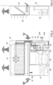
- Figure 1 designated as a whole by 1000 is a system for winter heating and summer cooling of environments provided according to the teachings of the present invention.
- the system 1000 substantially comprises:
- the multipurpose thermal-treatment apparatus 200 in turn comprises the following devices co-ordinated with one another:
- the multipurpose thermal-treatment apparatus 200 may be considered as made up of the compressor 20 to which a fluid working circuit 50 is connected comprising the devices 21, 22, 23, 24, 24, 26, 27, 29 connected to one another via pipes (illustrated in Figure 1 , but not numbered in order to simplify the present description).
- the working circuit 50 is in turn controlled by the electronic control unit 40 by means of the two temperature probes 29, 30.
- the apparatus 200 is equipped with a tank 45 for collection of the condensate that may form on the surface of the finned heat exchanger 24 and with a corresponding reservoir for accumulation of the condensate 46 itself.
- the system 1000 may also be equipped with a regulation device (not illustrated) with integrated weekly chronothermostat and interface for connection and programming thereof via mobile phone and/or tablet.
- a regulation device not illustrated
- integrated weekly chronothermostat and interface for connection and programming thereof via mobile phone and/or tablet.
- the multipurpose thermal-treatment apparatus 200 has been conceived for having dimensions (thickness, height, etc.) compatible with the main hot-water radiators currently existing on the market. Its modularity in width enables full application according to the existing spaces occupied by normal radiators.
- the presence of the second, radiant, heat exchanger 25 enables operation in the winter for prolonged periods without any intervention of the forced-ventilation assembly 47, thus guaranteeing a very quiet operation of the apparatus 200.
- the central heating and cooling equipment 100 necessarily has to be provided with a device for dissipation of the heat contained in the water leaving the heat exchanger 22, it being possible for this water to reach temperatures of 25°-30°C.
- a device for dissipation of the heat could be a refrigerator, or the like, which must be activated instead of the boiler (and which once again belongs to the central heating and cooling equipment 100).
- a possible thermal balance in the summer period is the following:
Landscapes
- Engineering & Computer Science (AREA)
- Chemical & Material Sciences (AREA)
- Combustion & Propulsion (AREA)
- Mechanical Engineering (AREA)
- General Engineering & Computer Science (AREA)
- Physics & Mathematics (AREA)
- Thermal Sciences (AREA)
- Life Sciences & Earth Sciences (AREA)
- Sustainable Development (AREA)
- Other Air-Conditioning Systems (AREA)
Claims (6)
- Système (1000) pour le chauffage en hiver et le climatisation en été d'environnements ; ledit système (1000) comprenant essentiellement :- un équipement central de chauffage et de climatisation (100) qui comprend un dispositif de chaudière ou une pompe à chaleur et un dispositif de réfrigération ; ledit équipement central de chauffage et de climatisation (100) étant adapté pour garantir une différence de température donnée entre un flux d'eau entrant et un flux d'eau sortant ;- au moins un appareil de traitement thermique (200) pour le traitement thermique de l'air dans au moins un environnement ; et- un réseau hydraulique pour la connexion entre ledit équipement central de chauffage et de climatisation (100) et ledit au moins un appareil de traitement thermique (200) ; dans lequel ledit système est configuré pour être raccordé à un système de chauffage par radiateurs de type traditionnel, le système étant caractérisé en ce que ledit appareil de traitement thermique (200) est un appareil de traitement thermique polyvalent (200) pour le chauffage en hiver et le climatisation en été dudit au moins un environnement; ledit appareil de traitement thermique polyvalent (200) comprenant :un compresseur (20) pour un fluide de travail ;un échangeur de chaleur (22) pour l'échange de chaleur entre l'eau provenant du système central et le fluide de travail ;une sonde de température (29) pour détecter la température du fluide de travail à la sortie dudit compresseur (20) ;une sonde de température (30) pour détecter la température du fluide de travail à l'entrée dudit compresseur (20) ;une sonde externe (31) pour détecter la température et l'humidité relative de l'environnement ; etune unité de commande électronique (40) pour commander les dispositifs précités qui nécessitent une régulation, et en ce queledit système (1000) comprend en outre à la fois un premier échangeur de chaleur (24) pour l'échange de chaleur entre le fluide de travail et l'air ambiant de type convectif et un deuxième échangeur de chaleur (25) pour l'échange de chaleur entre le fluide de travail et l'air ambiant de type radiant, ledit fluide de travail étant fourni à une température supérieure au point de rosée dans toutes les conditions climatiques.
- Système (1000) selon la revendication 1, caractérisé en ce qu'il comprend au moins un appareil de traitement thermique polyvalent (200) pour le chauffage en hiver et le climatisation en été d'au moins un environnement ; ledit appareil de traitement thermique polyvalent (200) étant configuré pour remplacer un radiateur normal, en termes de dimensions.
- Système (1000) selon l'une quelconque des revendications précédentes, caractérisé en ce que ledit appareil de traitement thermique polyvalent (200) comprend en outre au moins certains des dispositifs suivants :une vanne à quatre voies motorisée (21) pour l'inversion du cycle (de l'hiver à l'été, et vice versa) ;une vanne à détente thermique (23) de type électronique ;un premier clapet anti-retour (26A) et un second clapet anti-retour (26B) ;une vanne de fermeture (27) conçue pour connecter/déconnecter ledit second échangeur de chaleur (25) ;un séparateur gaz/liquide (28) ;une unité de commande électronique (40) pour commander les dispositifs précités qui nécessitent une régulation, ladite vanne à quatre voies motorisée (21), ledit échangeur de chaleur (22), ladite vanne à détente thermique (23), ledit premier échangeur de chaleur (24), ledit premier clapet anti-retour (26A), ledit second clapet anti-retour (26B), ladite vanne de fermeture (27) et ladite sonde de température (29) définissant un circuit de travail de fluide.
- Le système (1000) selon la revendication 3, caractérisé en ce qu'il comprend en outre un ensemble de ventilation forcée (60) pour la ventilation forcée de l'air traité.
- Le système (1000) selon la revendication 3 ou la revendication 4, caractérisé en ce qu'il comprend en outre au moins une buse de nébulisation (61) disposée entre lesdits deux échangeurs de chaleur (24, 25).
- Système (1000) selon l'une quelconque des revendications 3 à 5, caractérisé en ce que ledit deuxième échangeur de chaleur (25) de type radiant est directement relié audit circuit de travail fluidisé (50) qui utilise essentiellement un cycle de Carnot du fluide de travail.
Applications Claiming Priority (2)
| Application Number | Priority Date | Filing Date | Title |
|---|---|---|---|
| ITBO20140544 | 2014-10-03 | ||
| PCT/IB2015/057437 WO2016051336A1 (fr) | 2014-10-03 | 2015-09-29 | Système de chauffage en hiver et de climatisation en été |
Publications (3)
| Publication Number | Publication Date |
|---|---|
| EP3201535A1 EP3201535A1 (fr) | 2017-08-09 |
| EP3201535C0 EP3201535C0 (fr) | 2025-07-09 |
| EP3201535B1 true EP3201535B1 (fr) | 2025-07-09 |
Family
ID=51846769
Family Applications (1)
| Application Number | Title | Priority Date | Filing Date |
|---|---|---|---|
| EP15791742.8A Active EP3201535B1 (fr) | 2014-10-03 | 2015-09-29 | Système de chauffage en hiver et de climatisation en été |
Country Status (3)
| Country | Link |
|---|---|
| EP (1) | EP3201535B1 (fr) |
| MA (1) | MA40777A (fr) |
| WO (1) | WO2016051336A1 (fr) |
Families Citing this family (3)
| Publication number | Priority date | Publication date | Assignee | Title |
|---|---|---|---|---|
| CN111156627B (zh) * | 2020-01-17 | 2024-07-26 | 广东申菱环境系统股份有限公司 | 一种高效蒸发冷却式冷水机组及其控制方法 |
| CN111981552B (zh) * | 2020-05-22 | 2021-12-14 | 太原大四方节能环保股份有限公司 | 一种热泵与燃气锅炉联合供热系统与其调控方法 |
| IT202100008819A1 (it) | 2021-04-08 | 2022-10-08 | Innova S R L | Unità a pompa di calore con scambiatore ad acqua |
Citations (2)
| Publication number | Priority date | Publication date | Assignee | Title |
|---|---|---|---|---|
| FR2776757A1 (fr) * | 1998-03-24 | 1999-10-01 | Electricite De France | Climatiseur assurant le chauffage et le refroidissement |
| EP1748261A1 (fr) * | 2004-04-28 | 2007-01-31 | Daikin Industries, Ltd. | Systeme de climatisation |
Family Cites Families (10)
| Publication number | Priority date | Publication date | Assignee | Title |
|---|---|---|---|---|
| DE19515152A1 (de) * | 1995-04-19 | 1997-03-20 | Franz Dieter Seiwert | Klimaanlage Heizung |
| DE19620399A1 (de) * | 1996-05-21 | 1997-11-27 | Stiebel Eltron Gmbh & Co Kg | Verfahren zum Heizen mit einer Wärmepumpe |
| GB2334089A (en) * | 1998-02-03 | 1999-08-11 | Temperature Ltd | Heating and cooling system for a building |
| DE10114160C2 (de) * | 2001-03-22 | 2003-02-13 | Michael Schroeter | Anordnung zur Klimatisierung von Wohn- und Gewerberäumen mittels Wärmepumpe |
| US7716943B2 (en) * | 2004-05-12 | 2010-05-18 | Electro Industries, Inc. | Heating/cooling system |
| ATE507439T1 (de) * | 2008-03-20 | 2011-05-15 | Daikin Ind Ltd | Raumheizung und verfahren zur steuerung der raumheizung |
| GB0812169D0 (en) * | 2008-07-03 | 2008-08-13 | Lester Stephen | Water and room heater |
| JP2013185803A (ja) * | 2012-03-12 | 2013-09-19 | Panasonic Corp | ヒートポンプ式温水暖房装置 |
| FR2991029B1 (fr) * | 2012-05-22 | 2014-05-16 | Ciat Sa | Kit et methode de mise en oeuvre d'une installation de regulation de temperature pour un batiment |
| JP5781060B2 (ja) * | 2012-12-25 | 2015-09-16 | 三菱電機株式会社 | 空気調和装置 |
-
2015
- 2015-09-28 MA MA040777A patent/MA40777A/fr unknown
- 2015-09-29 WO PCT/IB2015/057437 patent/WO2016051336A1/fr not_active Ceased
- 2015-09-29 EP EP15791742.8A patent/EP3201535B1/fr active Active
Patent Citations (2)
| Publication number | Priority date | Publication date | Assignee | Title |
|---|---|---|---|---|
| FR2776757A1 (fr) * | 1998-03-24 | 1999-10-01 | Electricite De France | Climatiseur assurant le chauffage et le refroidissement |
| EP1748261A1 (fr) * | 2004-04-28 | 2007-01-31 | Daikin Industries, Ltd. | Systeme de climatisation |
Also Published As
| Publication number | Publication date |
|---|---|
| EP3201535A1 (fr) | 2017-08-09 |
| MA40777A (fr) | 2017-08-08 |
| EP3201535C0 (fr) | 2025-07-09 |
| WO2016051336A1 (fr) | 2016-04-07 |
Similar Documents
| Publication | Publication Date | Title |
|---|---|---|
| EP3726145B1 (fr) | Système de distribution d'énergie thermique de district | |
| US11041634B2 (en) | Local thermal energy consumer assembly and a local thermal energy generator assembly for a district thermal energy distribution system | |
| EP2281152A2 (fr) | Dispositif pour obtenir de la chaleur | |
| CN102725598A (zh) | 热泵系统 | |
| US8245949B2 (en) | Energy conservation system for using heat from air conditioning units to heat water supply lines | |
| CN102221270A (zh) | 一种热泵机组与太阳能联动的供冷暖和生活热水装置 | |
| EP3201535B1 (fr) | Système de chauffage en hiver et de climatisation en été | |
| CN203824158U (zh) | 一种多功能地源热泵机组 | |
| CN105115186A (zh) | 一种热泵热水机试验室冷热平衡装置 | |
| KR20160110946A (ko) | 에어 컨디셔닝 시스템, 그 주변 에어 컨디셔닝 유닛 및 가열 용도의 수배관 개선 방법 | |
| RS64475B1 (sr) | Sistemi za grejanja i hlađenja, i aparatura za konverziju postojećeg sistema za grejanje i postojećeg sistema za hlađenje u sistem za grejanje i hlađenje | |
| CN105650872A (zh) | 一种热水器 | |
| RS60768B1 (sr) | Uređaj i postupak za uticanje na temperaturu u objektu | |
| EP2224189B1 (fr) | Système de circulation d'eau associé à un cycle de réfrigération | |
| JP6016603B2 (ja) | 空気調和機および加熱ユニット | |
| EP3594588B1 (fr) | Dispositif de pompe à chaleur géothermique | |
| CN204084856U (zh) | 一种双温热泵热水系统 | |
| CN104154597A (zh) | 一种双用换热多联空调装置 | |
| KR101166858B1 (ko) | 지열원 냉난방 히트펌프용 냉난방 및 급탕 시스템 | |
| CN205102460U (zh) | 热泵系统 | |
| KR102042218B1 (ko) | 히트 펌프 | |
| CN104180599B (zh) | 用于超市的冷柜和热柜能源循环利用系统 | |
| EP3638957B1 (fr) | Appareil pour conditionnement thermique | |
| JP5909102B2 (ja) | 空調システム | |
| JP2010236737A (ja) | ヒートポンプ装置 |
Legal Events
| Date | Code | Title | Description |
|---|---|---|---|
| STAA | Information on the status of an ep patent application or granted ep patent |
Free format text: STATUS: THE INTERNATIONAL PUBLICATION HAS BEEN MADE |
|
| PUAI | Public reference made under article 153(3) epc to a published international application that has entered the european phase |
Free format text: ORIGINAL CODE: 0009012 |
|
| STAA | Information on the status of an ep patent application or granted ep patent |
Free format text: STATUS: REQUEST FOR EXAMINATION WAS MADE |
|
| 17P | Request for examination filed |
Effective date: 20170427 |
|
| AK | Designated contracting states |
Kind code of ref document: A1 Designated state(s): AL AT BE BG CH CY CZ DE DK EE ES FI FR GB GR HR HU IE IS IT LI LT LU LV MC MK MT NL NO PL PT RO RS SE SI SK SM TR |
|
| AX | Request for extension of the european patent |
Extension state: BA ME |
|
| DAX | Request for extension of the european patent (deleted) | ||
| STAA | Information on the status of an ep patent application or granted ep patent |
Free format text: STATUS: EXAMINATION IS IN PROGRESS |
|
| 17Q | First examination report despatched |
Effective date: 20221212 |
|
| RAP1 | Party data changed (applicant data changed or rights of an application transferred) |
Owner name: STILLE S.R.L. |
|
| RIN1 | Information on inventor provided before grant (corrected) |
Inventor name: MAISTRELLO, MARIO Inventor name: MANFROI, GIOVANNI |
|
| P01 | Opt-out of the competence of the unified patent court (upc) registered |
Effective date: 20230529 |
|
| GRAP | Despatch of communication of intention to grant a patent |
Free format text: ORIGINAL CODE: EPIDOSNIGR1 |
|
| STAA | Information on the status of an ep patent application or granted ep patent |
Free format text: STATUS: GRANT OF PATENT IS INTENDED |
|
| INTG | Intention to grant announced |
Effective date: 20250206 |
|
| GRAS | Grant fee paid |
Free format text: ORIGINAL CODE: EPIDOSNIGR3 |
|
| GRAA | (expected) grant |
Free format text: ORIGINAL CODE: 0009210 |
|
| STAA | Information on the status of an ep patent application or granted ep patent |
Free format text: STATUS: THE PATENT HAS BEEN GRANTED |
|
| AK | Designated contracting states |
Kind code of ref document: B1 Designated state(s): AL AT BE BG CH CY CZ DE DK EE ES FI FR GB GR HR HU IE IS IT LI LT LU LV MC MK MT NL NO PL PT RO RS SE SI SK SM TR |
|
| REG | Reference to a national code |
Ref country code: GB Ref legal event code: FG4D |
|
| REG | Reference to a national code |
Ref country code: CH Ref legal event code: EP |
|
| REG | Reference to a national code |
Ref country code: IE Ref legal event code: FG4D |
|
| REG | Reference to a national code |
Ref country code: DE Ref legal event code: R096 Ref document number: 602015091971 Country of ref document: DE |
|
| U01 | Request for unitary effect filed |
Effective date: 20250811 |
|
| U07 | Unitary effect registered |
Designated state(s): AT BE BG DE DK EE FI FR IT LT LU LV MT NL PT RO SE SI Effective date: 20250821 |
|
| U20 | Renewal fee for the european patent with unitary effect paid |
Year of fee payment: 11 Effective date: 20250922 |
|
| PG25 | Lapsed in a contracting state [announced via postgrant information from national office to epo] |
Ref country code: IS Free format text: LAPSE BECAUSE OF FAILURE TO SUBMIT A TRANSLATION OF THE DESCRIPTION OR TO PAY THE FEE WITHIN THE PRESCRIBED TIME-LIMIT Effective date: 20251109 |
|
| PG25 | Lapsed in a contracting state [announced via postgrant information from national office to epo] |
Ref country code: NO Free format text: LAPSE BECAUSE OF FAILURE TO SUBMIT A TRANSLATION OF THE DESCRIPTION OR TO PAY THE FEE WITHIN THE PRESCRIBED TIME-LIMIT Effective date: 20251009 |
|
| PG25 | Lapsed in a contracting state [announced via postgrant information from national office to epo] |
Ref country code: HR Free format text: LAPSE BECAUSE OF FAILURE TO SUBMIT A TRANSLATION OF THE DESCRIPTION OR TO PAY THE FEE WITHIN THE PRESCRIBED TIME-LIMIT Effective date: 20250709 |
|
| PG25 | Lapsed in a contracting state [announced via postgrant information from national office to epo] |
Ref country code: GR Free format text: LAPSE BECAUSE OF FAILURE TO SUBMIT A TRANSLATION OF THE DESCRIPTION OR TO PAY THE FEE WITHIN THE PRESCRIBED TIME-LIMIT Effective date: 20251010 |
|
| PG25 | Lapsed in a contracting state [announced via postgrant information from national office to epo] |
Ref country code: PL Free format text: LAPSE BECAUSE OF FAILURE TO SUBMIT A TRANSLATION OF THE DESCRIPTION OR TO PAY THE FEE WITHIN THE PRESCRIBED TIME-LIMIT Effective date: 20250709 |
|
| PG25 | Lapsed in a contracting state [announced via postgrant information from national office to epo] |
Ref country code: RS Free format text: LAPSE BECAUSE OF FAILURE TO SUBMIT A TRANSLATION OF THE DESCRIPTION OR TO PAY THE FEE WITHIN THE PRESCRIBED TIME-LIMIT Effective date: 20251009 |
|
| PG25 | Lapsed in a contracting state [announced via postgrant information from national office to epo] |
Ref country code: ES Free format text: LAPSE BECAUSE OF FAILURE TO SUBMIT A TRANSLATION OF THE DESCRIPTION OR TO PAY THE FEE WITHIN THE PRESCRIBED TIME-LIMIT Effective date: 20250709 |
|
| VS25 | Lapsed in a validation state [announced via postgrant information from nat. office to epo] |
Ref country code: MA Free format text: FAILURE TO ELECT DOMICILE IN THE NATIONAL COUNTRY Effective date: 20251010 |
|
| VS25 | Lapsed in a validation state [announced via postgrant information from nat. office to epo] |
Ref country code: MA Free format text: LAPSE BECAUSE OF FAILURE TO SUBMIT A TRANSLATION OF THE DESCRIPTION OR TO PAY THE FEE WITHIN THE PRESCRIBED TIME-LIMIT Effective date: 20250709 |
|
| PG25 | Lapsed in a contracting state [announced via postgrant information from national office to epo] |
Ref country code: SM Free format text: LAPSE BECAUSE OF FAILURE TO SUBMIT A TRANSLATION OF THE DESCRIPTION OR TO PAY THE FEE WITHIN THE PRESCRIBED TIME-LIMIT Effective date: 20250709 |
|
| PG25 | Lapsed in a contracting state [announced via postgrant information from national office to epo] |
Ref country code: CZ Free format text: LAPSE BECAUSE OF FAILURE TO SUBMIT A TRANSLATION OF THE DESCRIPTION OR TO PAY THE FEE WITHIN THE PRESCRIBED TIME-LIMIT Effective date: 20250709 |
|
| PG25 | Lapsed in a contracting state [announced via postgrant information from national office to epo] |
Ref country code: SK Free format text: LAPSE BECAUSE OF FAILURE TO SUBMIT A TRANSLATION OF THE DESCRIPTION OR TO PAY THE FEE WITHIN THE PRESCRIBED TIME-LIMIT Effective date: 20250709 |