EP3201651B1 - Gateway-übergreifendes interferenzmanagement und zugangssteuerung für ein cdma-satellitenkommunikationssystem - Google Patents
Gateway-übergreifendes interferenzmanagement und zugangssteuerung für ein cdma-satellitenkommunikationssystem Download PDFInfo
- Publication number
- EP3201651B1 EP3201651B1 EP15847846.1A EP15847846A EP3201651B1 EP 3201651 B1 EP3201651 B1 EP 3201651B1 EP 15847846 A EP15847846 A EP 15847846A EP 3201651 B1 EP3201651 B1 EP 3201651B1
- Authority
- EP
- European Patent Office
- Prior art keywords
- return link
- capacity level
- signal
- residual capacity
- interference
- Prior art date
- Legal status (The legal status is an assumption and is not a legal conclusion. Google has not performed a legal analysis and makes no representation as to the accuracy of the status listed.)
- Active
Links
Images


Classifications
-
- H—ELECTRICITY
- H04—ELECTRIC COMMUNICATION TECHNIQUE
- H04B—TRANSMISSION
- H04B17/00—Monitoring; Testing
- H04B17/30—Monitoring; Testing of propagation channels
- H04B17/309—Measuring or estimating channel quality parameters
- H04B17/336—Signal-to-interference ratio [SIR] or carrier-to-interference ratio [CIR]
-
- H—ELECTRICITY
- H04—ELECTRIC COMMUNICATION TECHNIQUE
- H04B—TRANSMISSION
- H04B17/00—Monitoring; Testing
- H04B17/30—Monitoring; Testing of propagation channels
- H04B17/309—Measuring or estimating channel quality parameters
- H04B17/345—Interference values
-
- H—ELECTRICITY
- H04—ELECTRIC COMMUNICATION TECHNIQUE
- H04B—TRANSMISSION
- H04B7/00—Radio transmission systems, i.e. using radiation field
- H04B7/14—Relay systems
- H04B7/15—Active relay systems
- H04B7/185—Space-based or airborne stations; Stations for satellite systems
- H04B7/1851—Systems using a satellite or space-based relay
- H04B7/18517—Transmission equipment in earth stations
-
- H—ELECTRICITY
- H04—ELECTRIC COMMUNICATION TECHNIQUE
- H04B—TRANSMISSION
- H04B7/00—Radio transmission systems, i.e. using radiation field
- H04B7/14—Relay systems
- H04B7/15—Active relay systems
- H04B7/185—Space-based or airborne stations; Stations for satellite systems
- H04B7/1853—Satellite systems for providing telephony service to a mobile station, i.e. mobile satellite service
-
- H—ELECTRICITY
- H04—ELECTRIC COMMUNICATION TECHNIQUE
- H04W—WIRELESS COMMUNICATION NETWORKS
- H04W52/00—Power management, e.g. Transmission Power Control [TPC] or power classes
- H04W52/04—Transmission power control [TPC]
- H04W52/30—Transmission power control [TPC] using constraints in the total amount of available transmission power
- H04W52/36—Transmission power control [TPC] using constraints in the total amount of available transmission power with a discrete range or set of values, e.g. step size, ramping or offsets
- H04W52/365—Power headroom reporting
-
- H—ELECTRICITY
- H04—ELECTRIC COMMUNICATION TECHNIQUE
- H04W—WIRELESS COMMUNICATION NETWORKS
- H04W88/00—Devices specially adapted for wireless communication networks, e.g. terminals, base stations or access point devices
- H04W88/16—Gateway arrangements
Definitions
- a code division multiple access (CDMA) system is an interference limited system in that the total system capacity is limited by the interference level.
- CDMA code division multiple access
- Conventional methods of interference management are typically based on a direct interference measurement or allow a certain maximum number of terminals using an equivalently same data rate (e.g., voice data rate) to be connected. See, e.g., Vanghi, Damnjanovic, and Vojcic, "The CDMA2000 System for Mobile Communications," Prentice Hall, Upper Saddle River, NJ, 2004 .
- the interference level is continuously measured at the receiver, and the user terminal transmissions are controlled to maintain the total received interference at the receiver within a certain limit.
- the number of terminals in transmission at any given time can be counted to sum up the total interference, assuming that each terminal generates a relatively equivalent amount of interference, and then the total summation is controlled to be within the limit.
- QoS quality of service
- the gateways are aware of and able to manage the interference level of the covered beams.
- UTs with different traffic types may be provided with differentiated QoS.
- real-time voice and video may have higher priority than other non-real-time data communications in obtaining network resources (e.g., bandwidth).
- the interference level is a function of the network traffic load (e.g., higher total traffics load could result in higher interference), and thus managing interference can be achieved via admission control with differentiated QoS provisioning.
- Embodiments of the present invention advantageously address the foregoing requirements and needs, as well as others, by providing a novel approach for indirect inter-gateway interference estimation, management and traffic admission control, which achieves effective estimation and control of the overall interference level of a satellite communications system (e.g., a CDMA satellite system), without using direct interference measurements, and permits each individual gateway to make admission decisions autonomously.
- the present approach comprises two components - one being indirect interference estimation (without requiring direct measurement), and a second being an admission control scheme that avoids overloading.
- an approach for estimating beam level interference using received signal-to-interference ratio (SIR), known UT location and UT reported power headroom (PHR), within a multi-gateway satellite communications system.
- SIR received signal-to-interference ratio
- PHR UT reported power headroom
- a gateway periodically estimates run-time return link interference.
- the interference estimation utilizes a UT's transmit power level (e.g., obtained from a UT power headroom report), the UT's location information and the antenna gain of both the UT and the satellite.
- the estimated interference can then be compared with a pre-defined threshold. If the estimated interference is lower than the threshold, the respective UT may be admitted subject to its interference contribution - otherwise, the UT is not admitted.
- the determination of whether to admit a UT is based on the equivalent resource the UT may consume, which may be calculated as a portion of its interference contribution. If the contributed interference from the UT does not make the overall interference exceed the threshold, then the UT can be admitted - otherwise, the UT is rejected. Additionally, when the estimated interference is higher than the threshold, the gateways are able to manage the overall load to by reducing the load of other connections to accommodate for admission of a new UT, for example, based relative priorities of the respective application or traffic type each UT is transmitting.
- the admission of example embodiments is thereby proactive and reactive, as an admission decision for multiple gateways would be the same as for one gateway, and each can operate autonomously given that the actual interference level would be transparent to the gateways. Further, taking into account system overload, each of the gateways autonomously performs interference relief measures to reduce the load and restore the interference to normal level.
- the admission control scheme thereby responds promptly and efficiently since the GWs do not need to communicate with each other in the process.
- a gateway receiver receives a plurality of return link signals, each return link signal being received via a satellite from a respective user terminal (UT) located within a satellite beam serviced by the GW terminal.
- a transmit power factor is determined for each UT based on the respective return link signal.
- An interference factor is determined for each UT based on the respective return link signal.
- a total interference factor for the UTs is determined based on the transmit power factors and the interference factors determined for the UTs.
- a residual capacity level is determined for the satellite beam based on the determined total interference factor and a noise power factor.
- the gateway receiver receives an admission request from a further UT requesting admission for transmission of a respective return link signal by the further UT.
- the gateway determines whether to grant the admission request based on a required capacity level for the respective return link signal of the further UT relative to the determined residual capacity level.
- a power-headroom value is obtained for each UT conveyed by the respective return link signal, wherein the transmit power factor for the UT is determined based on the respective power-headroom value and a maximum transmit power of the UT.
- the total interference factor is determined for the UTs by applying an averaging function based on a plurality of parameters for each UT, including the determined transmit power factor and the determined interference factor.
- an available residual capacity level is determined as the residual capacity level minus a minimum residual capacity level buffer, wherein the determination of whether to grant the admission request is based on the required capacity level for the respective return link signal of the further UT relative to the determined available residual capacity level.
- the available residual capacity level is determined in terms of a number of available resource units, wherein one resource unit reflects a capacity level associated with a base signal type with respect to the return link signals of the UTs located within the satellite beam serviced by the GW terminal, and the required capacity level for the respective return link signal of the further UT reflects a number of the available resource units required for transmission of the return link signal of the further UT to the GW terminal via the satellite beam.
- the respective return link signal of the further UT is characterized as one of two or more signal types with respect to the return link signals of the UTs located within the satellite beam serviced by the GW terminal, and an available residual capacity level is determined for each of the two or more signal types, wherein each available residual capacity level is determined as the residual capacity level minus a minimum residual capacity level buffer for the respective signal type. Further, the determination of whether to grant the admission request is based on the required capacity level for the signal type of the respective return link signal of the further UT relative to the determined available residual capacity level for the respective signal type.
- the available residual capacity level for each signal type is determined in terms of a number of available resource units for the respective signal type, wherein one resource unit reflects a capacity level associated with a base signal type with respect to the return link signals, and the required capacity level for the respective return link signal type of the further UT reflects a number of the available resource units for the respective signal type required for transmission of the return link signal of the further UT to the GW terminal via the satellite beam.
- a gateway (GW) terminal for indirect inter-gateway interference estimation, management and traffic admission control.
- the GW terminal comprises a receiver configured to receive a plurality of return link signals and to determine an interference factor for each UT based on the respective return link signal, each return link signal being received via a satellite from a respective user terminal (UT) located within a satellite beam serviced by the GW terminal.
- the GW terminal further comprises a processor configured to determine a transmit power factor for each UT based on the respective return link signal, to determine a total interference factor for the UTs from which the plurality of return link signals have been received based on the transmit power factors and the interference factors determined for the UTs, and to determine a residual capacity level for the satellite beam based on the determined total interference factor and a noise power factor.
- the receiver is further configured to receive an admission request from a further UT requesting admission for transmission of a respective return link signal by the further UT.
- the processor is further configured to determine whether to grant the admission request based on a required capacity level for the respective return link signal of the further UT relative to the determined residual capacity level.
- the processor is configured to obtain a power-headroom value for each UT conveyed by the respective return link signal, wherein the transmit power factor for the UT is determined based on the respective power-headroom value and a maximum transmit power of the UT.
- the interference factor for each UT reflects a signal to interference ratio estimated by the receiver based on the respective return link signal.
- the processor is configured to determine the total interference factor for the UTs by applying an averaging function based on a plurality of parameters for each UT, including the determined transmit power factor and the determined interference factor.
- the processor is further configured to determine an available residual capacity level as the residual capacity level minus a minimum residual capacity level buffer, wherein the determination of whether to grant the admission request is based on the required capacity level for the respective return link signal of the further UT relative to the determined available residual capacity level.
- the available residual capacity level is determined in terms of a number of available resource units, wherein one resource unit reflects a capacity level associated with a base signal type with respect to the return link signals of the UTs located within the satellite beam serviced by the GW terminal, and the required capacity level for the respective return link signal of the further UT reflects a number of the available resource units required for transmission of the return link signal of the further UT to the GW terminal via the satellite beam.
- the respective return link signal of the further UT is characterized as one of two or more signal types with respect to the return link signals of the UTs located within the satellite beam serviced by the GW terminal, and the processor is configured to determine an available residual capacity level for each of the two or more signal types, wherein each available residual capacity level is determined as the residual capacity level minus a minimum residual capacity level buffer for the respective signal type. Further, the determination of whether to grant the admission request is based on the required capacity level for the signal type of the respective return link signal of the further UT relative to the determined available residual capacity level for the respective signal type.
- the available residual capacity level for each signal type is determined in terms of a number of available resource units for the respective signal type, wherein one resource unit reflects a capacity level associated with a base signal type with respect to the return link signals, and the required capacity level for the respective return link signal type of the further UT reflects a number of the available resource units for the respective signal type required for transmission of the return link signal of the further UT to the GW terminal via the satellite beam.
- FIG. 1 illustrates a satellite communications system that employs approaches for indirect inter-gateway interference estimation, management and traffic admission control, where multiple user terminals (UTs) located in a common satellite beam are serviced by different respective gateways, in accordance with example embodiments.
- the coverage area of the satellite beam is managed by multiple gateways (GW1 and GW2).
- the multiple user terminals (UTs) in a single beam are associated with / serviced by different respective gateways, where each gateway has knowledge of only those UTs with which it is associated.
- the UTs 1a, 1b, ..., 1n are associated with the GW-1 and the UTs 2a, 2b, ..., 2m are associated with the GW-2, and all the UTs are located within a single satellite beam.
- the communication/transmission direction from the GW to the UT is referred to as the forward link (FL) or outroute, and the communication/transmission direction from the UT to the GW is referred to as the return link (RL) or inroute.
- FL forward link
- RL return link
- the GWs may not communicate with each other, for example, when the GWs are located in different countries.
- UTs 1a, 1b, ..., 1n generate interference to both the GW-1 and GW-2 when transmitting via GW-1
- the UTs 2a, 2b, ..., 2m generate interference to both the GW-1 and GW-2 when transmitting via GW-2.
- the interference experienced at a given GW, resulting from UT transmissions via other GWs shall be referred to herein as inter-GW interference.
- inter-GW interference shall be referred to herein as inter-GW interference.
- FIG. 2 illustrates a block diagram depicting a Gateway (GW), and highlighting certain GW elements that perform roles in the approaches for indirect inter-gateway interference estimation, management and traffic admission control, in accordance with example embodiments.
- the GW comprises at least one receiver (of which the figure depicts only one), an upper layer processor, a capacity and admission management module or processing section, memory storage and at least one transmitter (of which the figure depicts only one).
- the functioning of these GW elements with regard to embodiments of the present invention are described in further detail below.
- each UT transmits signals to the GW via the satellite (the return link or inroute)
- the UT provides a pilot signal along with the data signal - the pilot signal channel and the data channel are multiplexed together in a code division multiplexed manner.
- Power control is performed based on the pilot signal, and data signal power levels have a fixed relationship relative to the pilot power level depending on the type of data signal - each type of data signal will have a respective power that is based on a fixed relationship to the pilot signal power.
- a voice channel may have a power level that is always 10 dB higher than the pilot power level
- a 19.2 kbps data channel may have a power level that is always 13 dB higher than the pilot power level
- a 72 kbps data channel may have a power level that is always 20 dB higher than the pilot power level.
- the UT provides a power level field, in terms of a power headroom (PowerHR), indicating the power level at which the UT is transmitting.
- PowerHR power headroom
- the GW receiver receives the return link signals from the satellite, and demodulates and decodes the signals into the constituent respective UT signals.
- the receiver passes the UT signals on to the upper layer processor.
- the upper layer processor determines the pilot signal power for each UT, and stores the determined UT power figures for subsequent processing.
- the PowerHR results in a pilot output power that is independent of previous settings. For example, if setting PowerHR to 0 for a particular UT produces a pilot output power of -10 dBW, then a PowerHR of 10 dB shall produce a nominal value of -20 dBW.
- P tx-max is UT type and return carrier frequency dependent. Accordingly, when the GW receives the reported PowerHR, it can calculate the pilot power ( see Eq. (1a), above). It should be noted, however, that averaging may be needed to reduce uncertainty due to imperfect calibration. Given the pilot power P tx-pilot , the UT's actual power P tx-actual can be obtained via the power-to-pilot ratio, which is fixed for a certain transmission rate.
- PowerHR is used to facilitate return link interference estimation. PowerHR is reported to the gateway periodically. The GW can infer the actual transmit power given the PowerHR and power-to-pilot ratio. Further, the GW can perform this calculation for each UT with which the GW is associated, and thereby tracks the pilot power of all the respective UTs.
- the return link consists two parts: one from the terminal to the satellite (e.g., referred to as the uplink (UL) or mobile link), and the second from the satellite to the GW (e.g., referred to as the downlink (DL) or feeder link).
- the signal to interference ratio (SIR) is a composite of all the data over a composite of all the interference.
- the GW receiver estimates the SIR (signal to interference ratio - where the interference reflects the total interference experienced by the received signal based on all sources, including other terminals in the GW and in adjacent gateways, and the system noise (e.g., Gaussian noise)) for each UT transmission, and passes the estimated SIR values for each UT return signal to the upper layer processor.
- SIR signal to interference ratio
- the system noise e.g., Gaussian noise
- the upper layer processor performs the subsequent calculations with respect to total interference and residual capacity, based on the individual UT SIR values estimated by the receiver and the calculated individual UT pilot transmit powers, as described in further detail below.
- P i Tx , p the pilot transmit power for UT(i)
- d i the return link path loss
- g i S and g i U are the antenna gains for the satellite and UT, respectively
- ⁇ i is the shadowing
- I i is the total beam level interference plus thermal noise perceived by UT ( i ).
- the SIR is estimated by the GW receiver, and the pilot transmit power is derived based on the reported power headroom. Further, if the location of the UT is known, the return link path loss and satellite antenna gain can be determined/known. The nominal value of the gain of the UT antenna is also given as a constant as the maximum transmit power. If the shadowing loss is known, then the interference a UT experiences can be derived base on Eq. (2). The shadowing can be modeled as zero mean log-normal distribution. Accordingly, while the shadowing fluctuates and varies among UTs over the short term, the long term average can reasonably be considered as one.
- rain fade may cause substantial signal loss in Ku or Ka band, with example embodiments that contemplate a mobile CDMA system, where the return link runs on L-band or S-band that are much less susceptible to rain fade, the loss caused by rain fade can be considered as negligibly small.
- the PowerHR update interval may be of multiple frames.
- the updating interval of interference estimation therefore may be based on the frequency of UT PowerHR reports, and SIR may take the mean value of this interval.
- the approach according to example embodiments drops the assumption of known total number of UTs in a beam in deriving the beam level interference, and thus is independent of the topology of the coverage of a GW.
- a further advantage lies in that the derived beam level interference includes that from all sources in the same frequency (e.g., from the satellite and terrestrial terminals). The approach, according to example embodiments, therefore, is suitable for use in either single or multi-gateway interference management, as well as a hybrid satellite-terrestrial network sharing the same frequency.
- Residual Capacity At the return link, the received power from multiple UTs in the satellite visible coverage area could create mutual interference. When the aggregate interference exceeds a certain level, the system becomes overloaded, power control has difficulty achieving convergence, and no additional service can be provided unless the QoS for some existing service is degraded. In accordance with example embodiments, therefore, a proactive admission control approach is provided to prevent such overload.
- a reactive congestion control mitigates interference by reducing system load when overloading occurs.
- a factor referred to as residual capacity C RC is used as a basis for making admission determinations in view of the determined interference.
- the return link Nominal Capacity can be defined as the capacity measured in Voice Equivalent Resource (VER), which is the maximum amount of voice users that the system can support in one beam coverage under certain conditions.
- VER Voice Equivalent Resource
- the nominal capacity can then be used by a GW for setting the upper limit for admission control. While such an approach may work for a one GW situation, the approach would be significantly less reliable (and perhaps not work at all) for an inter-gateway admission control scenario, where multiple GWs share the same nominal capacity without knowing the admitted number of UTs at each GW. Further, this approach also requires certain assumptions to be true, such as perfect power control, same channel condition and SIR, etc. In reality, however, contrary to the required assumptions, there are various types of traffic with different SIR requirements, channel condition may change, and power control may not be perfect.
- a novel approach for a residual capacity model for UT admission criteria based on the estimated interference.
- the return interference from a GW beam (denoted as the reference beam) be I intra (namely, intra-beam interference)
- the interference from neighboring beams be I inter (namely, inter-beam interference).
- the ratio P N I total which is the noise portion of the total interference
- C RC the residual capacity
- the inter-beam interference I inter is largely proportional to the loading at the surrounding beam edge, which is in a state of soft handoff. Therefore, increasing the load in the reference beam also increases the interference of adjacent beams, which in turn is reflected as increased inter-beam interference in the reference beam.
- the variable ⁇ can be a preconfigured estimated value or be estimated at run-time. By way of example, based on simulation results, an estimated value for ⁇ falls within a range of 0.4 ⁇ ⁇ ⁇ 0.8.
- the above equation also infers that an i th user terminal consumes an interference level of 1 + ⁇ ⁇ i 1 + ⁇ i from the residual capacity.
- the residual capacity can be expressed as (where L 1 and L 2 are the number of UTs associated with each gateway, respectively):
- the range of C RC should be constrained as 0 ⁇ C RC ⁇ 1.
- admission control one purpose of the admission control algorithm is to allow each GW to autonomously take admission as long as the beam interference level allows it to do so. On the other hand, if a GW observes that the beam interference level is too high to deteriorate the existing services due to admission from other beams, this GW should start to unload the traffic by reducing or temporarily stopping some packet data transmissions.
- the upper layer processor may perform available VER calculations (as described below), and based on those calculations, the upper layer processor in combination with the capacity and admission management subsystem can perform the ultimate UT admission management and control of existing UT transmissions, in accordance with example embodiments of the present invention, to control overall interference and prevent system instability and overloading.
- a minimum threshold residual capacity C RC,min is set to prevent the system from operating too close to the nominal capacity, which may lead to instability.
- a voice equivalent resource is the equivalent radio resource used for one voice traffic channel, which is one dedicated voice channel.
- VER provides convenience for radio resource management - effectively as a common currency of unit of measure for determining available capacity to admit a further UT, based on the number of VERs the added UT will consume from the residual capacity (based on the application or type of data transmission the UT is attempting to add to the beam/system).
- a packet data channel may have the rate of one or multiple VERs - e.g., 19.2 kbps packet data may be viewed as being equivalent to two voice calls (requiring 2 VERs of residual capacity), and 70 kbps packet data may be viewed as being equivalent to six voice calls (requiring 6 VERs of residual capacity).
- each user terminal consumes 1 + ⁇ ⁇ ⁇ 1 + ⁇ ⁇ from the residual capacity (per VER), and thus each newly admitted UT will consume that much interference capacity out of the residual capacity. Accordingly, taking C RC,min . the available residual capacity of C RC - C RC,min should be able to accommodate the number of components of 1 + ⁇ ⁇ ⁇ 1 + ⁇ ⁇ required by a new UT seeking admission.
- the value of ⁇ may range from approximately 0.4 - 0.8, subject to UT location and beam coverage.
- N Avail VER may be rounded to an integer value, and when it is larger than 0, admission or rate increase can be assumed under the constraint of available VERs. N Avail VER becomes larger as C RC increases or ⁇ decreases.
- a problem may arise (e.g., where GW-1 considers admitting a higher priority real-time source, and GW-2 has an existing service of a lower priority data source). If the interference level is high, GW-1 could reject the request since it does not know or control the existing data service in GW-2. If one gateway oversees both services, it can admit the real-time source by releasing or reducing the rate of existing data source.
- multiple thresholds of the residual capacity may be set for services with different priorities. For example, a lower threshold of residual capacity requirement may be set for high priority services and a higher threshold for lower priority services.
- GW-1 If a real-time source is admitted by GW-1, it increases total interference level causing the system residual capacity lower.
- GW-2 which has existing data service will start to take measures to release or reduce the rate of data service, and thus restore the system residual capacity to the normal level.
- the GW in order to make room to admit a UT with a higher priority service, the GW can reduce the load of existing lower priority services, for example, by reducing the data rate of such services, which in turn would reduce the power transmission of the UTs whose data rate was lowered and consequently reduce the respective interference contributions to make room for the new higher priority UT.
- C RC , min D and C RC , min V denote the minimum threshold for non-real-time (e.g., data) and real-time (e.g., video) traffic flows, respectively.
- the admission and rate change criteria for inter-gateway resource management may be as follows (:
- the following provides example guidelines for the admission criteria.
- N Avail VER is shared by two gateways. Since N Avail VER is derived indirectly (in the sense not by counting existing UTs associated with one gateway), the observed time varying N Avail VER by each gateway reflects the current interference level taking into account the existing UTs in another beam. Therefore, the aforementioned admission criteria for multiple gateways would be the same as that for one gateway, and each can operate autonomously, and in a proactive fashion.
- the approach of example embodiments is also reactive in the sense that, when a beam is overloaded, it should reduce the interference level by reducing traffic load until the residual capacity is restored above the minimum threshold - for example, by reducing the rate of an existing packet data channel, or handing out a UT to another frequency band, or releasing an entire traffic channel.
- FIG. 3 illustrates a block diagram of a chip set that can be utilized in implementing example embodiments according to the present invention.
- the chip set includes, for instance, processor and memory components described with respect to FIG. 3 incorporated in one or more physical packages.
- a physical package includes an arrangement of one or more materials, components, and/or wires on a structural assembly (e.g., a baseboard or printed circuit board) to provide one or more characteristics such as physical strength, conservation of size, and/or limitation of electrical interaction.
- the chip set includes a communication mechanism such as a bus for passing information among the components of the chip set.
- a processor has connectivity to the bus to execute instructions/programs and process information stored in, for example, a memory.
- the processor may include one or more processing cores with each core configured to perform independently.
- a multi-core processor enables multiprocessing within a single physical package, such as two, four, eight, or greater numbers of processing cores.
- the processor may include one or more microprocessors configured in tandem via the bus to enable independent execution of instructions, pipelining, and multithreading.
- the processor may also be accompanied with one or more specialized components to perform certain processing functions and tasks such as one or more digital signal processors (DSP), and/or one or more application-specific integrated circuits (ASIC).
- DSP digital signal processors
- ASIC application-specific integrated circuits
- a DSP typically is configured to process real-time signals (e.g., sound or video) in real time independently of the processor.
- an ASIC can be configured to performed specialized functions not easily performed by a general purpose processor.
- Other specialized components to aid in performing the inventive functions described herein may include one or more field programmable gate arrays (FPGA) (not shown), one or more controllers (not shown), or one or more other special-purpose computer chips.
- FPGA field programmable gate arrays
- the processor and accompanying components have connectivity to the memory via the bus.
- the memory may include both dynamic memory (e.g., RAM) and static memory (e.g., ROM) for storing executable instructions that, when executed by the processor and/or the DSP and/or the ASIC, perform the process of example embodiments as described herein.
- the memory may also store the data associated with or generated by the execution of the process.
- the functionality of the example embodiments of the present invention may be provided by the chip set, in response to the processor executing an arrangement of program instructions contained in memory. Execution of the program instructions contained in memory causes the processor to perform the process steps and generate the results described herein, or equivalents thereof.
- One or more processors in a multi-processing arrangement can also be employed to execute the program instructions.
- hard-wired circuitry can be used in place of or in combination with software instructions to implement the example embodiments.
- embodiments of the present invention are not limited to any specific combination of hardware circuitry and software.
- FIG. 4 illustrates a computer system that can be utilized in the implementation of example embodiments according to the present invention.
- the computer system includes a bus or other communication mechanism for communicating information, and a processor coupled to the bus for processing information.
- the computer system also includes main memory, such as a random access memory (RAM) or other dynamic storage device, coupled to the bus for storing information and instructions to be executed by the processor.
- Main memory can also be used for storing temporary variables or other intermediate information during execution of instructions to be executed by the processor.
- the computer system further includes a read only memory (ROM) or other static storage device coupled to the bus for storing static information and instructions for the processor.
- ROM read only memory
- a storage device such as a magnetic disk or optical disk, is additionally coupled to the bus for storing information and instructions.
- dynamic and flexible approaches for selective dynamic disabling of transport layer handshake spoofing are provided by the computer system in response to the processor executing an arrangement of instructions contained in main memory.
- Such instructions can be read into main memory from another computer-readable medium, such as the storage device.
- Execution of the arrangement of instructions contained in main memory causes the processor to perform the process steps described herein.
- processors in a multi-processing arrangement may also be employed to execute the instructions contained in main memory.
- hard-wired circuitry is used in place of or in combination with software instructions to implement the embodiment of the present invention.
- embodiments of the present invention are not limited to any specific combination of hardware circuitry and software.
- the computer system also includes a communication interface coupled to bus.
- the communication interface provides a two-way data communication coupling to a network link connected to a local network.
- the communication interface may be a digital subscriber line (DSL) card or modem, an integrated services digital network (ISDN) card, a cable modem, or a telephone modem to provide a data communication connection to a corresponding type of telephone line.
- communication interface may be a local area network (LAN) card (e.g. for EthernetTM or an Asynchronous Transfer Mode (ATM) network) to provide a data communication connection to a compatible LAN.
- LAN local area network
- Wireless links can also be implemented.
- the communication interface for example, includes peripheral interface devices, such as a Universal Serial Bus (USB) interface, a PCMCIA (Personal Computer Memory Card International Association) interface, etc.
- USB Universal Serial Bus
- PCMCIA Personal Computer Memory Card International Association
- the network link typically provides data communication through one or more networks to other data devices.
- the network link provides a connection through local network to a host computer, which has connectivity to a network (e.g. a wide area network (WAN) or the global packet data communication network now commonly referred to as the "Internet") or to data equipment operated by service provider.
- the computer system sends messages and receives data, including program code, through the network(s), network link, and communication interface.
- a server (not shown) might transmit requested code belonging to an application program for implementing an embodiment of the present invention through the network, local network and communication interface.
- the processor executes the transmitted code while being received and/or store the code in storage device, or other non-volatile storage for later execution.
- Non-volatile media include, for example, optical or magnetic disks, such as storage device.
- Volatile media may include dynamic memory, such as main memory.
- Computer-readable media include, for example, a floppy disk, a flexible disk, hard disk, magnetic tape, any other magnetic medium, a CD ROM, CDRW, DVD, any other optical medium, punch cards, paper tape, optical mark sheets, any other physical medium with patterns of holes or other optically recognizable indicia, a RAM, a PROM, and EPROM, a FLASH EPROM, any other memory chip or cartridge, a carrier wave, or any other medium from which a computer can read.
- a floppy disk a flexible disk, hard disk, magnetic tape, any other magnetic medium, a CD ROM, CDRW, DVD, any other optical medium, punch cards, paper tape, optical mark sheets, any other physical medium with patterns of holes or other optically recognizable indicia, a RAM, a PROM, and EPROM, a FLASH EPROM, any other memory chip or cartridge, a carrier wave, or any other medium from which a computer can read.
- the instructions for carrying out at least part of the present invention may initially be borne on a magnetic disk of a remote computer.
- the remote computer loads the instructions into main memory and sends the instructions over a telephone line using a modem.
- a modem of a local computer system receives the data on the telephone line and uses an infrared transmitter to convert the data to an infrared signal and transmit the infrared signal to a portable computing device, such as a personal digital assistance (PDA) and a laptop.
- PDA personal digital assistance
- An infrared detector on the portable computing device receives the information and instructions borne by the infrared signal and places the data on a bus.
- the bus conveys the data to main memory, from which a processor retrieves and executes the instructions.
- the instructions received by main memory may optionally be stored on storage device either before or after execution by processor.
- a module or component may be composed of software component(s), which are stored in a memory or other computer readable storage medium, and executed by one or more processors or CPUs of the respective devices.
- a module may alternatively be composed of hardware component(s) or firmware component(s), or a combination of hardware, firmware and/or software components.
- example embodiments of the present invention may provide for various implementations (e.g., including hardware, firmware and/or software components), and, unless stated otherwise, all functions are performed by a CPU or a processor executing computer executable program code stored in a non-transitory memory or computer-readable storage medium, the various components can be implemented in different configurations of hardware, firmware, software, and/or a combination thereof. Except as otherwise disclosed herein, the various components shown in outline or in block form in the figures are individually well known and their internal construction and operation are not critical either to the making or using of this invention or to a description of the best mode thereof.
Landscapes
- Engineering & Computer Science (AREA)
- Computer Networks & Wireless Communication (AREA)
- Signal Processing (AREA)
- Physics & Mathematics (AREA)
- Astronomy & Astrophysics (AREA)
- Aviation & Aerospace Engineering (AREA)
- General Physics & Mathematics (AREA)
- Quality & Reliability (AREA)
- Electromagnetism (AREA)
- Radio Relay Systems (AREA)
- Mobile Radio Communication Systems (AREA)
Claims (22)
- Verfahren mit den Schritten:Empfangen, durch einen Empfänger eines Gateway(GW)-Terminals, einer Vielzahl von Rückverbindungssignalen, wobei jedes Rückverbindungssignal über einen Satelliten von einem entsprechenden Benutzerterminal (UT) empfangen wird, der in einem von dem GW-Terminal bedienten Satellitenstrahl liegt;Erhalten eines von dem entsprechenden Rückverbindungssignal übermittelten Leistungsreservewertes für jeden UT, wobei ein Übertragungsleistungsfaktor für den UT auf der Basis des jeweiligen Leistungsreservewertes und einer maximalen Übertragungsleistung des UT bestimmt wird;Bestimmen eines Interferenzfaktors für jeden UT auf der Basis des jeweiligen Rückverbindungssignals;Bestimmen eines gesamten Interferenzfaktors für die UTs, von welchen die Vielzahl von Rückverbindungssignalen empfangen worden sind, auf der Basis der für die UTs bestimmten Übertragungsleistungsfaktoren und der Interferenzfaktoren;Bestimmen eines Restkapazitätspegels für den Satellitenstrahl auf der Basis des bestimmten gesamten Interferenzfaktors und eines Rauschleistungsfaktors;Empfangen einer Zugangsanforderung von einem weiteren UT, welche den Zugang zur Übertragung eines entsprechenden Rückverbindungssignals durch den weiteren UT anfordert; undBestimmen, ob der Zugangsanforderung auf der Basis eines erforderlichen Kapazitätspegels für das entsprechende Rückverbindungssignal des weiteren UT bezüglich des bestimmten Restkapazitätspegels stattgegeben wird.
- Verfahren nach Anspruch 1, wobei der Interferenzfaktor für jedes UT ein von dem GW-Terminalempfänger geschätztes Signal-Interferenz-Verhältnis auf der Basis des entsprechenden Rückverbindungssignals widerspiegelt.
- Verfahren nach Anspruch 1, weiterhin mit dem Schritt:
Bestimmen eines verfügbaren Restkapazitätspegels als den Restkapazitätspegel abzüglich eines Mindestrestkapazitätspegel-Puffers, wobei die Bestimmung, ob der Zugangsanforderung stattgegeben wird, auf dem erforderlichen Kapazitätspegel für das entsprechende Rückverbindungssignal des weiteren UT bezüglich des bestimmten verfügbaren Restkapazitätspegels basiert. - Verfahren nach Anspruch 3, wobei der verfügbare Restkapazitätspegel hinsichtlich einer Anzahl verfügbarer Ressourceneinheiten bestimmt wird, wobei eine Ressourceneinheit einen einem Basissignaltyp zugeordneten Kapazitätspegel in Bezug auf die Rückverbindungssignale der UTs, die in dem von dem GW-Terminal bedienten Satellitenstrahl liegen, widerspiegelt und der erforderliche Kapazitätspegel für das entsprechende Rückverbindungssignal des weiteren UT eine Anzahl der verfügbaren Ressourceneinheiten widerspiegelt, die zur Übertragung des Rückverbindungssignals des weiteren UT an den GW-Terminal über den Satellitenstrahl benötigt werden.
- Verfahren nach Anspruch 4, wobei eine Ressourceneinheit einen Kapazitätspegel widerspiegelt, der für eine Sprachübertragungsverbindung als das Rückverbindungssignal des weiteren UT, als VER bezeichnet, benötigt wird, wobei:
 wobei φ einen effektiven Lastanstieg für eine VER Verbindung aufgrund von anderer Strahleninterferenz darstellt und γ̂ ein Durchschnitts- oder Ziel-Signal-Interferenz-Verhältnis zur Aufrechterhaltung einer VER Verbindung darstellt; unddie verfügbare Restkapazität hinsichtlich der Anzahl verfügbarer Ressourceneinheiten, als

wobei CRC die Restkapazität ist, CRC,min der Mindestrestkapazitätspegel-Puffer ist. - Verfahren nach Anspruch 1, wobei das entsprechende Rückverbindungssignal des weiteren UT als einer von zwei oder mehr Signaltypen hinsichtlich der Rückverbindungssignale der UTs gekennzeichnet ist, die in dem von dem GW-Terminal bedienten Satellitenstrahl liegen, wobei das Verfahren ferner Folgendes aufweist:Bestimmen eines verfügbaren Restkapazitätspegels für jeden der zwei oder mehr Signaltypen, wobei jeder verfügbare Restkapazitätspegel als der Restkapazitätspegel abzüglich eines Mindestrestkapazitätspegel-Puffers für den entsprechenden Signaltyp bestimmt wird;wobei die Bestimmung, ob der Zugangsanforderung stattgegeben wird, auf dem erforderlichen Kapazitätspegel für den Signaltyp des entsprechenden Rückverbindungssignals des weiteren UT bezüglich des bestimmten verfügbaren Restkapazitätspegels für den entsprechenden Signaltyp basiert.
- Verfahren nach Anspruch 6, wobei der verfügbare Restkapazitätspegel für jeden Signaltyp hinsichtlich einer Anzahl von verfügbaren Ressourceneinheiten für den entsprechenden Signaltyp bestimmt wird, wobei eine Ressourceneinheit einen bezüglich der Rückverbindungssignale einem Basissignaltyp zugeordneten Kapazitätspegel widerspiegelt, und der erforderliche Kapazitätspegel für den entsprechenden Rückverbindungssignaltyp des weiteren UT eine Anzahl der verfügbaren Ressourceneinheiten für den entsprechenden Signaltyp widerspiegelt, der zur Übertragung des Rückverbindungssignals des weiteren UT an den GW-Terminal über den Satellitenstrahl benötigt wird.
- Verfahren nach Anspruch 1, weiterhin mit dem Schritt:
Bestimmen des gesamten Interferenzfaktors für die UTs, indem eine Mittelungsfunktion auf der Basis einer Vielzahl von Parametern für jeden UT angewandt wird, einschließlich des bestimmten Übertragungsleistungsfaktors und des bestimmten Interferenzfaktors. - Verfahren nach Anspruch 8, weiterhin mit dem Schritt:Erhalten eines Leistungsreservewertes für jeden UT, der durch das entsprechende Rückverbindungssignal übermittelt wird, wobei der Übertragungsleistungsfaktor für den UT auf der Basis des entsprechenden Leistungsreservewertes und einer maximalen Übertragungsleistung des UT bestimmt wird; undwobei der Interferenzfaktor für jeden UT ein Signal-Interferenz-Verhältnis widerspiegelt, das von dem GW Terminalempfänger auf der Basis des entsprechenden Rückverbindungssignals geschätzt wird.
- Verfahren nach Anspruch 9, wobei die Vielzahl von Parametern, auf welchen die Mittelungsfunktion basiert, ferner einen oder mehrere aus einem Rückverbindungspfadverlust, einem Antennengewinn bezüglich des Satelliten, einem Antennengewinn bezüglich des UT und einem Shadowing-Faktor aufweist.
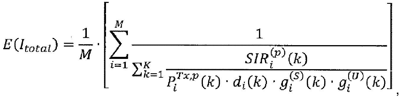
- Verfahren nach Anspruch 10, wobei die Mittelungsfunktion zum Bestimmen des gesamten Interferenzfaktors, als E(Itotal ) bezeichnet, wie folgt ist


- Gateway (GW)-Terminalvorrichtung mit:einem Empfänger, der dazu konfiguriert ist, eine Vielzahl von Rückverbindungssignalen zu empfangen und einen Interferenzfaktor für jeden UT auf der Basis des entsprechenden Rückverbindungssignals zu bestimmen, wobei jedes Rückverbindungssignal über einen Satelliten von einem entsprechenden Benutzerterminal (UT) empfangen wird, der in einem von der GW-Terminalvorrichtung bedienten Satellitenstrahl liegt; undeinem Prozessor, der dazu konfiguriert ist, einen durch das entsprechende Rückverbindungssignal übermittelten Leistungsreservewert für jeden UT zu erhalten, wobei ein Übertragungsleistungsfaktorfür das UT auf der Basis des entsprechenden Leistungsreservewertes und einer maximalen Übertragungsleistung des UT bestimmt wird, einen gesamten Interferenzfaktor für die UTs, von welchen die Vielzahl von Rückverbindungssignalen empfangen worden ist, auf der Basis der Übertragungsleistungsfaktoren und der für die UTs bestimmten Interferenzfaktoren zu bestimmen, und einen Restkapazitätspegel für den Satellitenstrahl auf der Basis des bestimmten gesamten Interferenzfaktors und eines Rauschleistungsfaktors zu bestimmen; undwobei der Empfänger ferner dazu konfiguriert ist, eine Zugangsanforderung von einem weiteren UT zu empfangen, die den Zugang zur Übertragung eines entsprechenden Rückverbindungssignals durch das weitere UT anfordert; undwobei der Prozessor ferner dazu konfiguriert ist, zu bestimmen, ob der Zugangsanforderung auf der Basis eines erforderlichen Kapazitätspegels für das entsprechende Rückverbindungssignal des weiteren UT in Bezug auf den bestimmten Restkapazitätspegel stattgegeben wird.
- GW-Terminalvorrichtung nach Anspruch 11, wobei der Interferenzfaktor für jeden UT ein von dem Empfänger geschätztes Signal-Interferenz-Verhältnis auf der Basis des entsprechenden Rückverbindungssignals widerspiegelt.
- GW-Terminalvorrichtung nach Anspruch 12, wobei der Prozessor ferner dazu konfiguriert ist, einen verfügbare Restkapazitätspegel als den Restkapazitätspegel abzüglich eines Mindestrestkapazitätspegel-Puffers zu bestimmen, wobei die Bestimmung, ob der Zugangsanforderung stattgegeben wird, auf dem erforderlichen Kapazitätspegel für das entsprechende Rückverbindungssignal des weiteren UT in Bezug auf den bestimmten verfügbaren Restkapazitätspegel basiert.
- GW-Terminalvorrichtung nach Anspruch 14, wobei der verfügbare Restkapazitätspegel hinsichtlich einer Anzahl von verfügbaren Ressourceneinheiten bestimmt wird, wobei eine Ressourceneinheit einen Kapazitätspegel widerspiegelt, der einem Basissignaltyp bezüglich der Rückverbindungssignale der UTs zugeordnet ist, welche in dem von der GW-Terminalvorrichtung bedienten Satellitenstrahl liegen, und der erforderliche Kapazitätspegel für das entsprechende Rückverbindungssignal des weiteren UT eine Anzahl der verfügbaren Ressourceneinheiten widerspiegelt, die zur Übertragung des Rückverbindungssignals des weiteren UT an die GW-Terminalvorrichtung über den Satellitenstrahl benötigt werden.
- GW-Terminalvorrichtung nach Anspruch 15, wobei eine Ressourceneinheit einen Kapazitätspegel widerspiegelt, der für eine Sprachübertragungsverbindung als das Rückverbindungssignal des weiteren UT benötigt wird, als VER bezeichnet, wobei:
 wobei φ einen effektiven Lastanstieg für eine VER Verbindung aufgrund von anderer Strahleninterferenz darstellt und γ̂ ein Durchschnitts- oder Ziel-Signal-Interferenz-Verhältnis zur Aufrechterhaltung einer VER Verbindung darstellt; unddie verfügbare Restkapazität hinsichtlich der Anzahl von verfügbaren Ressourceneinheiten, als

wobei CRC die Restkapazität ist, CRC,min der Mindestrestkapazitätspegel-Puffer ist. - GW-Terminalvorrichtung nach Anspruch 12, wobei das entsprechende Rückverbindungssignal des weiteren UT als einer von zwei oder mehr Signaltypen bezüglich der Rückverbindungssignale der UTs gekennzeichnet ist, die in dem von der GW-Terminalvorrichtung bedienten Satellitenstrahl liegen, wobei:der Prozessor dazu konfiguriert ist, einen verfügbaren Restkapazitätspegel für jeden der zwei oder mehr Signaltypen zu bestimmen, wobei jeder verfügbare Restkapazitätspegel als der Restkapazitätspegel abzüglich eines Mindestrestkapazitätspegel-Puffers für den entsprechenden Signaltyp bestimmt wird; undwobei die Bestimmung, ob der Zugangsanforderung stattgegeben wird, auf dem erforderlichen Kapazitätspegel für den Signaltyp des entsprechenden Rückverbindungssignals des weiteren UT in Bezug auf den bestimmten verfügbaren Restkapazitätspegel für den entsprechenden Signaltyp basiert.
- GW-Terminalvorrichtung nach Anspruch 17, wobei der verfügbare Restkapazitätspegel für jeden Signaltyp hinsichtlich einer Anzahl von verfügbaren Ressourceneinheiten für den entsprechenden Signaltyp bestimmt wird, wobei eine Ressourceneinheit einen einem Basissignaltyp bezüglich der Rückverbindungssignale zugeordneten Kapazitätspegel widerspiegelt, und der erforderliche Kapazitätspegel für den entsprechenden Rückverbindungssignaltyp des weiteren UT eine Anzahl der verfügbaren Ressourceneinheiten für den entsprechenden Signaltyp widerspiegelt, die zur Übertragung des Rückverbindungssignals des weiteren UT an die GW-Terminalvorrichtung über den Satellitenstrahl benötigt werden.
- GW-Terminalvorrichtung nach Anspruch 12, wobei der Prozessor dazu konfiguriert ist, den gesamten Interferenzfaktor für die UTs zu bestimmen, indem eine Mittelungsfunktion auf der Basis einer Vielzahl von Parametern für jeden UT angewandt wird, einschließlich des bestimmten Übertragungsleistungsfaktors und des bestimmten Interferenzfaktors.
- GW-Terminalvorrichtung nach Anspruch 19, wobei der Prozessor ferner dazu konfiguriert ist, einen durch das entsprechende Rückverbindungssignal übermittelten Leistungsreservewert für jeden UT zu erhalten, wobei der Übertragungsleistungsfaktor für den UT auf der Basis des entsprechenden Leistungsreservewertes und einer maximalen Übertragungsleistung des UT bestimmt wird, und wobei der Interferenzfaktor für jeden UT ein durch den GW-Empfänger geschätztes Signal-Interferenz-Verhältnis auf der Basis des entsprechenden Rückverbindungssignal widerspiegelt.
- GW-Terminalvorrichtung nach Anspruch 20, wobei die Vielzahl von Parametern, auf welchen die Mittelungsfunktion basiert, ferner einen oder mehrere aus einem Rückverbindungspfadverlust, einem Antennengewinn bezüglich des Satelliten, einem Antennengewinn bezüglich des UT und einem Shadowing-Faktor aufweist.
- GW-Terminvorrichtung nach Anspruch 21, wobei die Mittelungsfunktion zum Bestimmen des gesamten Interferenzfaktors, als E(Itotal) bezeichnet, wie folgt ist


Applications Claiming Priority (2)
| Application Number | Priority Date | Filing Date | Title |
|---|---|---|---|
| US201462057221P | 2014-09-29 | 2014-09-29 | |
| PCT/US2015/053040 WO2016054111A1 (en) | 2014-09-29 | 2015-09-29 | Inter-gateway interference management and admission control for a cdma satellite communications system |
Publications (3)
| Publication Number | Publication Date |
|---|---|
| EP3201651A1 EP3201651A1 (de) | 2017-08-09 |
| EP3201651A4 EP3201651A4 (de) | 2018-05-23 |
| EP3201651B1 true EP3201651B1 (de) | 2019-04-03 |
Family
ID=55585691
Family Applications (1)
| Application Number | Title | Priority Date | Filing Date |
|---|---|---|---|
| EP15847846.1A Active EP3201651B1 (de) | 2014-09-29 | 2015-09-29 | Gateway-übergreifendes interferenzmanagement und zugangssteuerung für ein cdma-satellitenkommunikationssystem |
Country Status (6)
| Country | Link |
|---|---|
| US (1) | US10020901B2 (de) |
| EP (1) | EP3201651B1 (de) |
| BR (1) | BR112017006494B1 (de) |
| CA (1) | CA2963119C (de) |
| MX (1) | MX377659B (de) |
| WO (1) | WO2016054111A1 (de) |
Families Citing this family (6)
| Publication number | Priority date | Publication date | Assignee | Title |
|---|---|---|---|---|
| KR101741307B1 (ko) * | 2015-02-13 | 2017-05-29 | 한국전자통신연구원 | 위성 통신 시스템의 리턴 링크 강우 감쇄 보상 방법 및 그 시스템 |
| US10097316B2 (en) * | 2015-10-05 | 2018-10-09 | Qualcomm Incorporated | HARQ handling at inter-beam handover |
| TWI754372B (zh) | 2016-10-21 | 2022-02-01 | 華碩電腦股份有限公司 | 無線通訊系統中波束運作之功率餘量回報之方法及設備 |
| US10462755B2 (en) | 2017-06-16 | 2019-10-29 | Qualcomm Incorporated | Techniques and apparatuses for power headroom reporting in new radio |
| EP3664497B1 (de) * | 2017-08-04 | 2024-02-21 | NTT DoCoMo, Inc. | Benutzergerät und basisstationsvorrichtung |
| US11564286B2 (en) | 2021-04-30 | 2023-01-24 | L3Harris Technologies, Inc. | Gateway link management between disjoint subnetworks in a CDMA MANET |
Family Cites Families (28)
| Publication number | Priority date | Publication date | Assignee | Title |
|---|---|---|---|---|
| US6091933A (en) * | 1997-01-03 | 2000-07-18 | Globalstar L.P. | Multiple satellite system power allocation by communication link optimization |
| US6252915B1 (en) * | 1998-09-09 | 2001-06-26 | Qualcomm Incorporated | System and method for gaining control of individual narrowband channels using a wideband power measurement |
| US6356531B1 (en) * | 1999-06-07 | 2002-03-12 | Qualcomm Incorporated | Monitoring of CDMA load and frequency reuse based on reverse link signal-to-noise ratio |
| US6298242B1 (en) * | 1999-07-22 | 2001-10-02 | Qualcomm Inc. | Method and apparatus for reducing frame error rate through signal power adjustment |
| US6456850B1 (en) * | 1999-08-17 | 2002-09-24 | Lucent Technologies Inc. | Method for preventing overload conditions in communication systems |
| US6609002B1 (en) * | 1999-09-15 | 2003-08-19 | Hrl Laboratories, Llc | Method and apparatus for predictive QoS routing for broad band low earth satellite networks |
| BR0014053A (pt) * | 1999-09-17 | 2002-05-21 | Nokia Corp | Processo e sistema para estimativa do aumento de potência de interferência na direção de ligação superior devido a uma transação em um sistema de telecomunicações celular de espectro disperso, processos de controle de admissão em um sistema de telecomunicações celular de espectro disperso, e para programação de pacotes de dados em um sistema de telecomunicações celular de espectro disperso, e, elemento de rede de uma rede de telecomunicações celular |
| US6904017B1 (en) * | 2000-05-08 | 2005-06-07 | Lucent Technologies Inc. | Method and apparatus to provide centralized call admission control and load balancing for a voice-over-IP network |
| US6975609B1 (en) * | 2000-05-30 | 2005-12-13 | Telefonaktiebolaget Lm Ericsson (Publ) | Dynamic call admission |
| US6628921B1 (en) * | 2000-10-13 | 2003-09-30 | Globalstar L.P. | Return link channel loading of multiple satellites with multiple spread spectrum user terminals |
| US6985739B2 (en) * | 2000-12-15 | 2006-01-10 | Telefonaktiebolaget Lm Ericsson (Publ) | Admission and congestion control in a CDMA-based mobile radio communications system |
| US7266103B2 (en) * | 2001-10-25 | 2007-09-04 | Qualcomm Incorporated | Controlling forward link traffic channel power |
| US7593691B2 (en) * | 2002-02-12 | 2009-09-22 | Atc Technologies, Llc | Systems and methods for controlling a level of interference to a wireless receiver responsive to a power level associated with a wireless transmitter |
| US7633895B2 (en) * | 2002-06-24 | 2009-12-15 | Qualcomm Incorporated | Orthogonal code division multiple access on return link of satellite links |
| US7471645B2 (en) * | 2002-10-25 | 2008-12-30 | Hughes Network Systems, Llc | Method and system for multicast in a broadband satellite system |
| FR2862824B1 (fr) * | 2003-11-25 | 2006-02-10 | Cit Alcatel | Procede de gestion de communications dans un reseau de communications a acces aleatoire et a longs delais de transmission d'acquitements de demande d'acces |
| CN101980456A (zh) * | 2005-01-05 | 2011-02-23 | Atc科技有限责任公司 | 卫星通信系统和方法中带有多用户检测和干扰减少的自适应波束形成 |
| KR20070072795A (ko) * | 2006-01-02 | 2007-07-05 | 삼성전자주식회사 | 통신 시스템에서 스케쥴링 방법 및 시스템 |
| EP2074769A2 (de) * | 2006-10-06 | 2009-07-01 | ViaSat, Inc. | Dynamisches feedback zur anpassung einer rate ausgehender verbindungen in einem multiraten-abwärtsstrom |
| AU2009228928B2 (en) * | 2008-03-26 | 2014-04-03 | Cellular Communications Equipment Llc | Extension of power headroom reporting and trigger conditions |
| US8654701B2 (en) * | 2008-11-13 | 2014-02-18 | Telefonaktiebolaget Lm Ericsson (Publ) | Creation and signalling of UE lists to support frequency selective repeater operation |
| US8483609B2 (en) * | 2009-07-08 | 2013-07-09 | Viasat, Inc. | Interference resistant satellite link power control using uplink noise measurements |
| US8385223B2 (en) * | 2009-07-08 | 2013-02-26 | Viasat, Inc. | Interference resistant satellite link power control using downlink beacon |
| CN102742331B (zh) * | 2010-04-01 | 2015-08-26 | Lg电子株式会社 | 在无线接入系统中控制上行功率的方法和装置 |
| US8537767B2 (en) * | 2010-04-06 | 2013-09-17 | Sunplus Technology Co., Ltd | Method for performing power headroom reporting procedure and PHR MAC control element |
| US9179363B2 (en) * | 2011-08-12 | 2015-11-03 | Telefonaktiebolaget Lm Ericsson (Publ) | Systems and methods for determining a coupling characteristic in a radio communications network |
| US8660006B2 (en) * | 2011-11-29 | 2014-02-25 | Hughes Network Systems, Llc | Method and system for traffic management and resource allocation on a shared access network |
| US20150110068A1 (en) * | 2013-10-23 | 2015-04-23 | Qualcomm Incorporated | Serving cell and neighbor cell path loss ratio reporting |
-
2015
- 2015-09-29 CA CA2963119A patent/CA2963119C/en active Active
- 2015-09-29 US US14/869,884 patent/US10020901B2/en active Active
- 2015-09-29 MX MX2017004062A patent/MX377659B/es active IP Right Grant
- 2015-09-29 EP EP15847846.1A patent/EP3201651B1/de active Active
- 2015-09-29 WO PCT/US2015/053040 patent/WO2016054111A1/en not_active Ceased
- 2015-09-29 BR BR112017006494-4A patent/BR112017006494B1/pt active IP Right Grant
Non-Patent Citations (1)
| Title |
|---|
| None * |
Also Published As
| Publication number | Publication date |
|---|---|
| BR112017006494B1 (pt) | 2023-09-26 |
| US10020901B2 (en) | 2018-07-10 |
| US20160094481A1 (en) | 2016-03-31 |
| CA2963119A1 (en) | 2016-04-07 |
| CA2963119C (en) | 2023-01-31 |
| MX377659B (es) | 2025-03-11 |
| MX2017004062A (es) | 2017-08-28 |
| EP3201651A4 (de) | 2018-05-23 |
| WO2016054111A1 (en) | 2016-04-07 |
| BR112017006494A2 (pt) | 2018-07-03 |
| EP3201651A1 (de) | 2017-08-09 |
Similar Documents
| Publication | Publication Date | Title |
|---|---|---|
| EP3201651B1 (de) | Gateway-übergreifendes interferenzmanagement und zugangssteuerung für ein cdma-satellitenkommunikationssystem | |
| US9655055B2 (en) | Wireless communication system, transmission power control apparatus, base station apparatus, parameter providing apparatus, and transmission power control method | |
| US10425864B2 (en) | Methods and apparatuses for processing UE context of UE | |
| EP2601765B1 (de) | Verfahren und vorrichtung zur reduzierung des overheads bei der datenübertragung | |
| US20170048925A1 (en) | Apparatus and method for managing network of drone | |
| JP2023538994A (ja) | ProSeリモート及び中継エンティティによるQoS管理 | |
| US9699088B2 (en) | Service plan based flow control | |
| US9066278B2 (en) | Communication apparatus, method, and computer implementable product for admission control | |
| US11595071B2 (en) | Controlling transmitter output | |
| CN104010358B (zh) | 上行传输的方法、终端设备及通信系统 | |
| US9402235B2 (en) | Non-cooperative power control for large-scale antenna systems | |
| US12010627B2 (en) | Uplink power control of a terminal device | |
| US20150009841A1 (en) | Apparatus and method for formating virtual cell in a virtual cell network system | |
| CN106879058B (zh) | 发射功率控制方法、基站以及用户设备ue | |
| Susanto et al. | On the reduction of interference effect using power control for device-to-device communication underlying cellular communication network | |
| US20150358921A1 (en) | Fast Fading Power Restriction | |
| US20150358925A1 (en) | Radio communication system, radio station, and method for controlling transmission power | |
| CN101534547B (zh) | 一种移动终端及下行功率控制方法 | |
| US9001686B2 (en) | Interference estimation with TDM | |
| EP4042756B1 (de) | Verbesserung des durchschnittlichen eirp-regelintervalls durch zeitausgeblendete planung | |
| CN113711502B (zh) | 用于协调控制平均等效各向同性辐射功率的方法和设备 | |
| US20180376355A1 (en) | Service optimization processing method, device, and system | |
| KR20130015094A (ko) | D2d통신 단말의 전력 제어 방법 및 d2d통신 세션 개설 방법 | |
| US20220400521A1 (en) | Network entity, user equipment and method | |
| US20170127450A1 (en) | Data transmission control method and device |
Legal Events
| Date | Code | Title | Description |
|---|---|---|---|
| STAA | Information on the status of an ep patent application or granted ep patent |
Free format text: STATUS: THE INTERNATIONAL PUBLICATION HAS BEEN MADE |
|
| PUAI | Public reference made under article 153(3) epc to a published international application that has entered the european phase |
Free format text: ORIGINAL CODE: 0009012 |
|
| STAA | Information on the status of an ep patent application or granted ep patent |
Free format text: STATUS: REQUEST FOR EXAMINATION WAS MADE |
|
| 17P | Request for examination filed |
Effective date: 20170406 |
|
| AK | Designated contracting states |
Kind code of ref document: A1 Designated state(s): AL AT BE BG CH CY CZ DE DK EE ES FI FR GB GR HR HU IE IS IT LI LT LU LV MC MK MT NL NO PL PT RO RS SE SI SK SM TR |
|
| AX | Request for extension of the european patent |
Extension state: BA ME |
|
| DAV | Request for validation of the european patent (deleted) | ||
| DAX | Request for extension of the european patent (deleted) | ||
| A4 | Supplementary search report drawn up and despatched |
Effective date: 20180419 |
|
| RIC1 | Information provided on ipc code assigned before grant |
Ipc: G01S 19/21 20100101AFI20180413BHEP Ipc: H04B 7/185 20060101ALN20180413BHEP |
|
| GRAP | Despatch of communication of intention to grant a patent |
Free format text: ORIGINAL CODE: EPIDOSNIGR1 |
|
| STAA | Information on the status of an ep patent application or granted ep patent |
Free format text: STATUS: GRANT OF PATENT IS INTENDED |
|
| INTG | Intention to grant announced |
Effective date: 20181108 |
|
| RIC1 | Information provided on ipc code assigned before grant |
Ipc: G01S 19/21 20100101AFI20181022BHEP Ipc: H04B 7/185 20060101ALN20181022BHEP |
|
| GRAS | Grant fee paid |
Free format text: ORIGINAL CODE: EPIDOSNIGR3 |
|
| GRAA | (expected) grant |
Free format text: ORIGINAL CODE: 0009210 |
|
| STAA | Information on the status of an ep patent application or granted ep patent |
Free format text: STATUS: THE PATENT HAS BEEN GRANTED |
|
| AK | Designated contracting states |
Kind code of ref document: B1 Designated state(s): AL AT BE BG CH CY CZ DE DK EE ES FI FR GB GR HR HU IE IS IT LI LT LU LV MC MK MT NL NO PL PT RO RS SE SI SK SM TR |
|
| REG | Reference to a national code |
Ref country code: GB Ref legal event code: FG4D |
|
| REG | Reference to a national code |
Ref country code: CH Ref legal event code: EP Ref country code: AT Ref legal event code: REF Ref document number: 1116417 Country of ref document: AT Kind code of ref document: T Effective date: 20190415 |
|
| REG | Reference to a national code |
Ref country code: DE Ref legal event code: R096 Ref document number: 602015027805 Country of ref document: DE |
|
| REG | Reference to a national code |
Ref country code: IE Ref legal event code: FG4D |
|
| REG | Reference to a national code |
Ref country code: NL Ref legal event code: MP Effective date: 20190403 |
|
| REG | Reference to a national code |
Ref country code: LT Ref legal event code: MG4D |
|
| REG | Reference to a national code |
Ref country code: AT Ref legal event code: MK05 Ref document number: 1116417 Country of ref document: AT Kind code of ref document: T Effective date: 20190403 |
|
| PG25 | Lapsed in a contracting state [announced via postgrant information from national office to epo] |
Ref country code: NL Free format text: LAPSE BECAUSE OF FAILURE TO SUBMIT A TRANSLATION OF THE DESCRIPTION OR TO PAY THE FEE WITHIN THE PRESCRIBED TIME-LIMIT Effective date: 20190403 |
|
| PG25 | Lapsed in a contracting state [announced via postgrant information from national office to epo] |
Ref country code: ES Free format text: LAPSE BECAUSE OF FAILURE TO SUBMIT A TRANSLATION OF THE DESCRIPTION OR TO PAY THE FEE WITHIN THE PRESCRIBED TIME-LIMIT Effective date: 20190403 Ref country code: AL Free format text: LAPSE BECAUSE OF FAILURE TO SUBMIT A TRANSLATION OF THE DESCRIPTION OR TO PAY THE FEE WITHIN THE PRESCRIBED TIME-LIMIT Effective date: 20190403 Ref country code: PT Free format text: LAPSE BECAUSE OF FAILURE TO SUBMIT A TRANSLATION OF THE DESCRIPTION OR TO PAY THE FEE WITHIN THE PRESCRIBED TIME-LIMIT Effective date: 20190803 Ref country code: SE Free format text: LAPSE BECAUSE OF FAILURE TO SUBMIT A TRANSLATION OF THE DESCRIPTION OR TO PAY THE FEE WITHIN THE PRESCRIBED TIME-LIMIT Effective date: 20190403 Ref country code: FI Free format text: LAPSE BECAUSE OF FAILURE TO SUBMIT A TRANSLATION OF THE DESCRIPTION OR TO PAY THE FEE WITHIN THE PRESCRIBED TIME-LIMIT Effective date: 20190403 Ref country code: CZ Free format text: LAPSE BECAUSE OF FAILURE TO SUBMIT A TRANSLATION OF THE DESCRIPTION OR TO PAY THE FEE WITHIN THE PRESCRIBED TIME-LIMIT Effective date: 20190403 Ref country code: NO Free format text: LAPSE BECAUSE OF FAILURE TO SUBMIT A TRANSLATION OF THE DESCRIPTION OR TO PAY THE FEE WITHIN THE PRESCRIBED TIME-LIMIT Effective date: 20190703 Ref country code: LT Free format text: LAPSE BECAUSE OF FAILURE TO SUBMIT A TRANSLATION OF THE DESCRIPTION OR TO PAY THE FEE WITHIN THE PRESCRIBED TIME-LIMIT Effective date: 20190403 Ref country code: HR Free format text: LAPSE BECAUSE OF FAILURE TO SUBMIT A TRANSLATION OF THE DESCRIPTION OR TO PAY THE FEE WITHIN THE PRESCRIBED TIME-LIMIT Effective date: 20190403 |
|
| PG25 | Lapsed in a contracting state [announced via postgrant information from national office to epo] |
Ref country code: RS Free format text: LAPSE BECAUSE OF FAILURE TO SUBMIT A TRANSLATION OF THE DESCRIPTION OR TO PAY THE FEE WITHIN THE PRESCRIBED TIME-LIMIT Effective date: 20190403 Ref country code: GR Free format text: LAPSE BECAUSE OF FAILURE TO SUBMIT A TRANSLATION OF THE DESCRIPTION OR TO PAY THE FEE WITHIN THE PRESCRIBED TIME-LIMIT Effective date: 20190704 Ref country code: PL Free format text: LAPSE BECAUSE OF FAILURE TO SUBMIT A TRANSLATION OF THE DESCRIPTION OR TO PAY THE FEE WITHIN THE PRESCRIBED TIME-LIMIT Effective date: 20190403 Ref country code: LV Free format text: LAPSE BECAUSE OF FAILURE TO SUBMIT A TRANSLATION OF THE DESCRIPTION OR TO PAY THE FEE WITHIN THE PRESCRIBED TIME-LIMIT Effective date: 20190403 Ref country code: BG Free format text: LAPSE BECAUSE OF FAILURE TO SUBMIT A TRANSLATION OF THE DESCRIPTION OR TO PAY THE FEE WITHIN THE PRESCRIBED TIME-LIMIT Effective date: 20190703 |
|
| PG25 | Lapsed in a contracting state [announced via postgrant information from national office to epo] |
Ref country code: IS Free format text: LAPSE BECAUSE OF FAILURE TO SUBMIT A TRANSLATION OF THE DESCRIPTION OR TO PAY THE FEE WITHIN THE PRESCRIBED TIME-LIMIT Effective date: 20190803 Ref country code: AT Free format text: LAPSE BECAUSE OF FAILURE TO SUBMIT A TRANSLATION OF THE DESCRIPTION OR TO PAY THE FEE WITHIN THE PRESCRIBED TIME-LIMIT Effective date: 20190403 |
|
| REG | Reference to a national code |
Ref country code: DE Ref legal event code: R097 Ref document number: 602015027805 Country of ref document: DE |
|
| PG25 | Lapsed in a contracting state [announced via postgrant information from national office to epo] |
Ref country code: DK Free format text: LAPSE BECAUSE OF FAILURE TO SUBMIT A TRANSLATION OF THE DESCRIPTION OR TO PAY THE FEE WITHIN THE PRESCRIBED TIME-LIMIT Effective date: 20190403 Ref country code: EE Free format text: LAPSE BECAUSE OF FAILURE TO SUBMIT A TRANSLATION OF THE DESCRIPTION OR TO PAY THE FEE WITHIN THE PRESCRIBED TIME-LIMIT Effective date: 20190403 Ref country code: RO Free format text: LAPSE BECAUSE OF FAILURE TO SUBMIT A TRANSLATION OF THE DESCRIPTION OR TO PAY THE FEE WITHIN THE PRESCRIBED TIME-LIMIT Effective date: 20190403 Ref country code: SK Free format text: LAPSE BECAUSE OF FAILURE TO SUBMIT A TRANSLATION OF THE DESCRIPTION OR TO PAY THE FEE WITHIN THE PRESCRIBED TIME-LIMIT Effective date: 20190403 |
|
| PLBE | No opposition filed within time limit |
Free format text: ORIGINAL CODE: 0009261 |
|
| STAA | Information on the status of an ep patent application or granted ep patent |
Free format text: STATUS: NO OPPOSITION FILED WITHIN TIME LIMIT |
|
| PG25 | Lapsed in a contracting state [announced via postgrant information from national office to epo] |
Ref country code: SM Free format text: LAPSE BECAUSE OF FAILURE TO SUBMIT A TRANSLATION OF THE DESCRIPTION OR TO PAY THE FEE WITHIN THE PRESCRIBED TIME-LIMIT Effective date: 20190403 Ref country code: IT Free format text: LAPSE BECAUSE OF FAILURE TO SUBMIT A TRANSLATION OF THE DESCRIPTION OR TO PAY THE FEE WITHIN THE PRESCRIBED TIME-LIMIT Effective date: 20190403 |
|
| 26N | No opposition filed |
Effective date: 20200106 |
|
| PG25 | Lapsed in a contracting state [announced via postgrant information from national office to epo] |
Ref country code: TR Free format text: LAPSE BECAUSE OF FAILURE TO SUBMIT A TRANSLATION OF THE DESCRIPTION OR TO PAY THE FEE WITHIN THE PRESCRIBED TIME-LIMIT Effective date: 20190403 |
|
| PG25 | Lapsed in a contracting state [announced via postgrant information from national office to epo] |
Ref country code: MC Free format text: LAPSE BECAUSE OF FAILURE TO SUBMIT A TRANSLATION OF THE DESCRIPTION OR TO PAY THE FEE WITHIN THE PRESCRIBED TIME-LIMIT Effective date: 20190403 Ref country code: SI Free format text: LAPSE BECAUSE OF FAILURE TO SUBMIT A TRANSLATION OF THE DESCRIPTION OR TO PAY THE FEE WITHIN THE PRESCRIBED TIME-LIMIT Effective date: 20190403 |
|
| REG | Reference to a national code |
Ref country code: CH Ref legal event code: PL |
|
| PG25 | Lapsed in a contracting state [announced via postgrant information from national office to epo] |
Ref country code: CH Free format text: LAPSE BECAUSE OF NON-PAYMENT OF DUE FEES Effective date: 20190930 Ref country code: LI Free format text: LAPSE BECAUSE OF NON-PAYMENT OF DUE FEES Effective date: 20190930 Ref country code: LU Free format text: LAPSE BECAUSE OF NON-PAYMENT OF DUE FEES Effective date: 20190929 Ref country code: IE Free format text: LAPSE BECAUSE OF NON-PAYMENT OF DUE FEES Effective date: 20190929 |
|
| REG | Reference to a national code |
Ref country code: BE Ref legal event code: MM Effective date: 20190930 |
|
| PG25 | Lapsed in a contracting state [announced via postgrant information from national office to epo] |
Ref country code: BE Free format text: LAPSE BECAUSE OF NON-PAYMENT OF DUE FEES Effective date: 20190930 |
|
| PG25 | Lapsed in a contracting state [announced via postgrant information from national office to epo] |
Ref country code: FR Free format text: LAPSE BECAUSE OF NON-PAYMENT OF DUE FEES Effective date: 20190930 |
|
| PG25 | Lapsed in a contracting state [announced via postgrant information from national office to epo] |
Ref country code: CY Free format text: LAPSE BECAUSE OF FAILURE TO SUBMIT A TRANSLATION OF THE DESCRIPTION OR TO PAY THE FEE WITHIN THE PRESCRIBED TIME-LIMIT Effective date: 20190403 |
|
| PG25 | Lapsed in a contracting state [announced via postgrant information from national office to epo] |
Ref country code: MT Free format text: LAPSE BECAUSE OF FAILURE TO SUBMIT A TRANSLATION OF THE DESCRIPTION OR TO PAY THE FEE WITHIN THE PRESCRIBED TIME-LIMIT Effective date: 20190403 Ref country code: HU Free format text: LAPSE BECAUSE OF FAILURE TO SUBMIT A TRANSLATION OF THE DESCRIPTION OR TO PAY THE FEE WITHIN THE PRESCRIBED TIME-LIMIT; INVALID AB INITIO Effective date: 20150929 |
|
| PG25 | Lapsed in a contracting state [announced via postgrant information from national office to epo] |
Ref country code: MK Free format text: LAPSE BECAUSE OF FAILURE TO SUBMIT A TRANSLATION OF THE DESCRIPTION OR TO PAY THE FEE WITHIN THE PRESCRIBED TIME-LIMIT Effective date: 20190403 |
|
| PGFP | Annual fee paid to national office [announced via postgrant information from national office to epo] |
Ref country code: DE Payment date: 20250805 Year of fee payment: 11 |
|
| PGFP | Annual fee paid to national office [announced via postgrant information from national office to epo] |
Ref country code: GB Payment date: 20250807 Year of fee payment: 11 |