EP3202199B1 - Bestimmung einer mittenfrequenz in einem unlizenzierten frequenzband zur verwendung - Google Patents
Bestimmung einer mittenfrequenz in einem unlizenzierten frequenzband zur verwendung Download PDFInfo
- Publication number
- EP3202199B1 EP3202199B1 EP14799909.8A EP14799909A EP3202199B1 EP 3202199 B1 EP3202199 B1 EP 3202199B1 EP 14799909 A EP14799909 A EP 14799909A EP 3202199 B1 EP3202199 B1 EP 3202199B1
- Authority
- EP
- European Patent Office
- Prior art keywords
- network node
- measurement
- tor
- frequencies
- accurate measurement
- Prior art date
- Legal status (The legal status is an assumption and is not a legal conclusion. Google has not performed a legal analysis and makes no representation as to the accuracy of the status listed.)
- Active
Links
Images
Classifications
-
- H—ELECTRICITY
- H04—ELECTRIC COMMUNICATION TECHNIQUE
- H04W—WIRELESS COMMUNICATION NETWORKS
- H04W24/00—Supervisory, monitoring or testing arrangements
- H04W24/10—Scheduling measurement reports ; Arrangements for measurement reports
-
- H—ELECTRICITY
- H04—ELECTRIC COMMUNICATION TECHNIQUE
- H04W—WIRELESS COMMUNICATION NETWORKS
- H04W16/00—Network planning, e.g. coverage or traffic planning tools; Network deployment, e.g. resource partitioning or cells structures
- H04W16/14—Spectrum sharing arrangements between different networks
-
- H—ELECTRICITY
- H04—ELECTRIC COMMUNICATION TECHNIQUE
- H04W—WIRELESS COMMUNICATION NETWORKS
- H04W24/00—Supervisory, monitoring or testing arrangements
-
- H—ELECTRICITY
- H04—ELECTRIC COMMUNICATION TECHNIQUE
- H04W—WIRELESS COMMUNICATION NETWORKS
- H04W24/00—Supervisory, monitoring or testing arrangements
- H04W24/02—Arrangements for optimising operational condition
-
- H—ELECTRICITY
- H04—ELECTRIC COMMUNICATION TECHNIQUE
- H04W—WIRELESS COMMUNICATION NETWORKS
- H04W72/00—Local resource management
-
- H—ELECTRICITY
- H04—ELECTRIC COMMUNICATION TECHNIQUE
- H04W—WIRELESS COMMUNICATION NETWORKS
- H04W72/00—Local resource management
- H04W72/04—Wireless resource allocation
- H04W72/044—Wireless resource allocation based on the type of the allocated resource
- H04W72/0453—Resources in frequency domain, e.g. a carrier in FDMA
-
- H—ELECTRICITY
- H04—ELECTRIC COMMUNICATION TECHNIQUE
- H04W—WIRELESS COMMUNICATION NETWORKS
- H04W72/00—Local resource management
- H04W72/20—Control channels or signalling for resource management
- H04W72/23—Control channels or signalling for resource management in the downlink direction of a wireless link, i.e. towards a terminal
-
- H—ELECTRICITY
- H04—ELECTRIC COMMUNICATION TECHNIQUE
- H04W—WIRELESS COMMUNICATION NETWORKS
- H04W72/00—Local resource management
- H04W72/50—Allocation or scheduling criteria for wireless resources
- H04W72/54—Allocation or scheduling criteria for wireless resources based on quality criteria
- H04W72/542—Allocation or scheduling criteria for wireless resources based on quality criteria using measured or perceived quality
Definitions
- the invention relates to a method, a network node, a computer program and a computer program product for determining a centre frequency in an unlicensed frequency band to use.
- LTE-U Long Term Evolution in Unlicensed
- 3GPP 3 rd Generation Partnership Project
- LTE-U can be deployed to use the 5 GHz band, which is currently used mostly for WiFi.
- LTE-U can be used to deploy LTE as Supplemental Downlink (SDL), with the PCell (Primary Cell) always operating on a carrier in a licensed band.
- SDL Supplemental Downlink
- PCell Primary Cell
- US 2012/039284 discloses techniques for control signaling and channel selection in cognitive Long Term Evolution (LTE).
- LTE cognitive Long Term Evolution
- a method, operable by a mobile entity that involves receiving, on a licensed channel, broadcasted channel usage information regarding at least one unlicensed channel used by one or more network nodes.
- a method for determining a centre frequency in an unlicensed frequency band to use for downlink communication in a cellular network is performed in a network node and comprises the steps of: performing a coarse pre-scan when the network node is in a transmit time slot, yielding respective coarse measurement of signal levels for a plurality of frequencies in the unlicensed frequency band; performing an accurate measurement when the network node is in a receive time slot, yielding respective accurate measurement of signal levels for a plurality of frequencies in the unlicensed frequency band; and determining at least one frequency to use as a centre frequency for a downlink communication channel in the unlicensed frequency band wherein the centre frequency is selected such that frequencies for which the coarse measurement and/or the accurate measurement indicate a high signal level is avoided.
- both the transmit time slot and the receive time slot can be used to evaluate frequencies to find a good frequency to use for a channel for downlink communication for a cellular network within the unlicensed frequency band. This allows more time to evaluate frequencies, leading to a better evaluation than if only the transmit time slot is used or if only the receive time slot is used.
- the step of performing a coarse pre-scan may be performed using a transmitter observation receiver, TOR.
- the step of performing a measurement to yield an accurate measurement may be performed using the TOR receiver with a first configurable gain; in which case the step of performing a coarse pre-scan is performed using the TOR with a second configurable gain.
- the first configurable gain is higher than the second configurable gain.
- the step of performing a measurement to yield an accurate measurement may be performed using the TOR receiver and a low noise amplifier; in which case the step of performing a coarse pre-scan is performed using the TOR without the low noise amplifier.
- the step of performing a measurement to yield an accurate measurement may be performed using a receive chain of the network node arranged to be used also for receiving uplink communication.
- the method may further comprise a step of: determining a set of candidate frequencies as the frequencies for which the course measurements of signal levels are lower than a threshold level: in which case the step of performing an accurate measurement is only performed for the set of candidate frequencies.
- the step of determining at least one frequency may be performed in the same receive time slot in which the step of performing the accurate measurement is performed.
- a network node for determining a centre frequency in an unlicensed frequency band to use for downlink communication in a cellular network.
- the network node comprises: a processor; and a memory storing instructions that, when executed by the processor, causes the network node to: perform a coarse pre-scan when the network node is in a transmit time slot, yielding a coarse measurement of signal levels for a plurality of frequencies in the unlicensed frequency band; perform an accurate measurement when the network node is in a receive time slot, yielding an accurate measurement of signal levels for a plurality of frequencies in the unlicensed frequency band; and determine at least one frequency to use as a centre frequency for a downlink communication channel in the unlicensed frequency band, wherein the centre frequency is selected such that frequencies for which the coarse measurement and/or the accurate measurement indicate a high signal level is avoided.
- the instructions to perform a coarse pre-scan may be performed using a transmitter observation receiver, TOR.
- the instructions to perform a measurement to yield an accurate measurement may be performed using the TOR receiver with a first configurable gain; in which case the instructions to perform a coarse pre-scan are executed using the TOR with a second configurable gain. In such a case, the first configurable gain is higher than the second configurable gain.
- the instructions to perform a measurement to yield an accurate measurement may be performed using the TOR receiver and a low noise amplifier; in which case the instructions to perform a coarse pre-scan are executed using the TOR without the low noise amplifier.
- the instructions to perform an accurate measurement may be executed using a receive chain of the network node also used for receiving uplink communication.
- the instructions may further comprise instructions that, when executed by the processor, causes the network node to: determine a set of candidate frequencies as the frequencies for which the course measurements of signal levels are lower than a threshold level; in which case the instructions to perform an accurate measurement are only performed for the set of candidate frequencies.
- the instructions to determine at least one frequencies may comprise instructions that, when executed by the processor, causes the network node to determine at least one frequency in the same receive time slot in which the instructions to perform the accurate measurement are executed.
- a computer program for determining a centre frequency in an unlicensed frequency band to use for downlink communication in a cellular network.
- the computer program comprises computer program code which, when run on a network node causes the network node to: perform a coarse pre-scan when the network node is in a transmit time slot, yielding a coarse measurement of signal levels for a plurality of frequencies in the unlicensed frequency band; perform an accurate measurement when the network node is in a receive time slot, yielding an accurate measurement of signal levels for a plurality of frequencies in the unlicensed frequency band; and determine at least one frequency to use as a centre frequency for a downlink communication channel in the unlicensed frequency band, wherein the centre frequency is selected such that frequencies for which the coarse measurement and/or the accurate measurement indicate a high signal level is avoided.
- a computer program product comprising a computer program according to the third aspect and a computer readable means on which the computer program is stored.
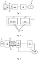
- Fig 1 is a schematic diagram illustrating a cellular communication network 8 where embodiments presented herein may be applied.
- the cellular communication network 8 comprises a core network 3 and one or more network nodes 1, here in the form of radio base stations being evolved Node Bs, also known as eNode Bs or eNBs.
- the network node is also referred to as a radio base station (RBS) herein.
- the network node 1 could also be in the form of Node Bs, BTSs (Base Transceiver Stations) and/or BSSs (Base Station Subsystems), etc.
- the network node 1 provides radio connectivity over a wireless interface 4a-b to a plurality of wireless devices 2.
- wireless device is also known as mobile communication terminal, user equipment (UE), mobile terminal, user terminal, user agent, wireless terminal, machine-to-machine device etc., and can be, for example, what today are commonly known as a mobile phone or a tablet/laptop with wireless connectivity.
- the term wireless is here to be construed as having the ability to perform wireless communication. More specifically, the wireless device 2 can comprise a number of wires for internal and/or external purposes.
- the wireless device 2 is also referred to as a UE herein.
- the cellular communication network 8 may e.g. comply with any one or a combination of LTE (Long Term Evolution), W-CDMA (Wideband Code Division Multiplex), EDGE (Enhanced Data Rates for GSM (Global System for Mobile communication) Evolution), GPRS (General Packet Radio Service), CDMA2000 (Code Division Multiple Access 2000), or any other current or future wireless network, such as LTE-Advanced, as long as the principles described hereinafter are applicable.
- LTE Long Term Evolution
- W-CDMA Wideband Code Division Multiplex
- EDGE Enhanced Data Rates for GSM (Global System for Mobile communication) Evolution
- GPRS General Packet Radio Service
- CDMA2000 Code Division Multiple Access 2000
- any other current or future wireless network such as LTE-Advanced, as long as the principles described hereinafter are applicable.
- uplink (UL) communication 4a occurs from the wireless device 2 to the network node 1 and downlink (DL) communication 4b occurs from the network node 1 to the wireless device 2.
- UL uplink
- DL downlink
- the quality of the wireless radio interface to each wireless device 2 can vary over time and depending on the position of the wireless device 2, due to effects such as fading, multipath propagation, interference, etc.
- the network node 1 is also connected to the core network 3 for connectivity to central functions and a wide area network 7, such as the Internet.
- Fig 2 is a schematic diagram illustrating an environment in which embodiments presented herein can be deployed.
- the wireless interface also known ad the air interface, for LTE-U is shown in Fig 2 .
- the wireless device also known as mobile terminal (UE) 2 is connected to LTE network via wireless interface 4 comprising two air interfaces: the primary carrier 31 which is in a (licensed) 3GPP frequency band and the secondary carrier 31' which is in an unlicensed frequency band (ISM (Industrial, Scientific and Medical) band).
- ISM Intelligent, Scientific and Medical
- the secondary carrier 31' operates as a Supplemental Downlink (SDL) mode, where there is only transmission data in the DL (Downlink) direction (from the RBS to the wireless device 2.
- SDL Supplemental Downlink
- the primary carrier 31 may utilise LTE FDD (Frequency Division Duplex) and/or TDD (Time Division Duplex) and it provides control signalling, mobility and user data while the secondary carrier(s) 31' use unlicensed spectrum with best-effort user data in DL. In is also planned that UL data can be supported by the secondary carrier 31'. Hence, the SDL band may be used as a bi-directional communication channel in the future.
- the secondary carrier 31' may utilise LTE FDD (Frequency Division Duplex) and/or TDD (Time Division Duplex).
- Fig 3 is a schematic diagram illustrating a network topology in which embodiments presented herein can be applied.
- the LTE RBS 1 also known as eNB
- the first operational band (PCell) 31 can e.g. operate at 3GPP band (transmission and reception) and the SDL 31' is only DL (Transmission) e.g. at 4915-5850 MHz.
- this frequency can be also used by 5GHz Wifi which can cause significant interference for the SDL 4b.
- the inventors have realised that an improved network utilisation with reduced external interference is achieved by accurately measuring and selecting the best channel frequency for LTE-U. This is established using fast decision making on used transmission and / or reception frequency.
- the LTE-U can use a TOR (Transmitter Observation Receiver) receiver in two different modes, a coarse detection mode during the transmit time slot and an accurate detection mode during the receive time slot. In this way, a fast and accurate decision on used transmit frequency is established in one cycle of a transmission time slot and a reception time slot.
- TOR Transmitter Observation Receiver
- the TOR receiver When both DL and UL are used for the secondary carrier(s), the TOR receiver is still used for coarse detection mode during the transmit time slot and the LTE-U receiver is used for accurate detection mode during the receive time slot to thereby establish fast and accurate decision on used transmit and receive frequency.
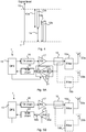
- Fig 4 illustrates how the dynamic range of a TOR receiver is utilised in a network node 1 of Fig 1 where Time Division Duplex, TDD or Frequency Division Duplex (FDD) is used.
- TDD implies that communication in either uplink or downlink is performed, but not both simultaneously (on a particular frequency band) and FDD implies that communication for uplink and downlink are performed simultaneously with dedicated frequency bands.
- the vertical axis represents received signal level, or signal strength. There is a maximum received signal level 10 and a minimum received signal level 11.
- a first dynamic range 13a for signal is used when the TOR receiver is used to perform a high signal level coarse pre-scan 12a. Low signals 14, such as noise signals, below the first dynamic range 13a are not detected in this mode.
- a second dynamic range 13b for signals is then used for a low signal level accurate detection 12b.
- An embodiment to accomplish a switch between the two modes is performed using a bypass of a low noise amplifier (LNA), controlled by a digital front end 15 and explained in more detail below.
- LNA low noise amplifier
- the LNA is bypassed and in the accurate detection 12b, the LNA is active.
- the different modes are used to comply with own transmission signal and to be able to detect smaller signal level during receiver period, as illustrated in the Fig 4 .
- Figs 5A-B are schematic diagrams illustrating some components of embodiments of a network node 1 employed for SDL only for LTE-U.
- the network node 1 includes a digital front end (DFE) 15, a transmitter (TX) chain 16, a high efficiency power amplifier (PA) 17 and a TOR receiver in a TOR chain 22 for DPD (Digital Pre Distortion), connected to a first filter 19a via a directional coupler 18.
- DFE digital front end
- TX transmitter
- PA high efficiency power amplifier
- TOR receiver in a TOR chain 22 for DPD (Digital Pre Distortion) connected to a first filter 19a via a directional coupler 18.
- Alternative methods to implement the directional coupler 18 are to use at least one of a coupler, a coupling capacitor or a circulator.
- the first filter 19a is connected to a first antenna 20a for wireless communication with wireless devices as described above.
- DPD DPD is used to create an inverse function of the distortion generated by the PA 17.
- the effects of the distortion from the PA is reduced or even essentially eliminated.
- LTE-U SDL RBS It is beneficial to select the radio transmit frequency for LTE-U SDL RBS so that a channel is selected for a transmission where interference from WiFi and / or other LTE-U transmissions (or from any other source) is as low as possible.
- fast measurement and selection of frequency channel for LTE-U is achieved by using the TOR receiver in the TOR chain 22 which is also used for DPD.
- An LNA 23 with bypass ability, using bypass switches 21, is provided between the TOR chain 22 and the directional coupler 18 to establish measurements during transmit (LNA bypass mode) or DPD active mode and receive (LNA active) or DPD inactive periods. Therefore, the TOR receiver in the TOR chain 22 can be used in two different modes, where the LNA bypass mode, when the switches 21 are in a state to bypass the LNA 23, is a coarse detection mode and the LNA active mode, when the switches 21 are in a state to employ the LNA 23, is an accurate detection mode.
- a sample of a transmission signal is detected via directional coupler 18 and convoyed to TOR receiver in the TOR chain 22.
- the sample of the transmission signal is relatively high, whereby the first dynamic range 13a ( Fig 4 ) for received signals is used in the TOR receiver.
- the LNA 23 is bypassed in order to enhance the dynamic range of the TOR receiver to receive the transmission signal sample linearly.
- the TOR receiver 22 may detect interference signals which are within the first dynamic range 13a for a coarse pre-scan 12a ( Fig 4 ).
- the TOR receiver in the TOR chain 22 and/or DFE 15 may include multiple filters implemented using one or more a physical filter components and/or digital filter components to attenuate unwanted signals, like the sample from the own transmission. In this way, the interference signal detection is made easier and more accurate.
- the operational frequency of the TOR receiver may be changed when the operational mode of the TOR is changed from DPD operation to an interference signal detection mode.
- the TOR receiver can be used during those inactive DPD slots for other purposes, such as the detection of interference signals described herein. When DPD is inactive, the TOR receiver may then be tuned to other frequencies as needed to detect interference signals. As described above, the LNA 23 can be used to detect lower signal levels (see dynamic range 13b of Fig 4 ).
- the TOR receiver in the TOR chain 22 By using the TOR receiver in the TOR chain 22 to detect signal levels for various frequencies, this is achieved without the need for any separate receive chain. This is beneficial since the transmitter for the SDL may very well not have a receive chain.
- the TOR receiver in the TOR chain 22 is typically already present to be used for DPD.
- the decision where to allocate LTE-U transmission in the frequency domain and optimal transmission power level can be done in the DFE 15 or in a base band processing unit (not shown).
- the DFE 15 can provide measurement data to the baseband processing unit for channel and transmission power selection.
- the decision can be made based on measured signal levels at different LTE-U frequencies.
- Decision threshold for measured signal level may be predefined or dynamic, i.e. adapted during the operation to current signal levels.
- the mode is controlled by the DFE 15.
- the network node 1 includes more than one antenna.
- the network node may include a second antenna 20b which may be connected to a second filter 19b which is further connected to the LNA 23 and the TOR chain 22.
- This alternative embodiment may improve the interference signal detection capability of the TOR receiver in the TOR chain 22, since own transmission signal is attenuated by an antenna isolation between the first antenna 20a, used for transmissions, and the second antenna 20b used for reception to the TOR chain.
- a second dynamic range 13b ( Fig 4 ) for signals is enhanced and used for a low signal level accurate detection 12b. If there are multiple antennas or signal detection paths for the interference signal detection, an method shown in figure 8A may decide which signal path or signal information are used in different steps 40, 41 and 42.
- Fig 5B there are no bypass switches as in Fig 5A around the LNA 23.
- a control signal from the DFE 15 to the LNA 23 increases the gain of the LNA to be able to detect signals of lower signal levels (see second dynamic range 13b of Fig 4 ).
- the DFE 15 controls the LNA 23 to reduce its gain to increase the detectable signal levels (see first dynamic range 13a of Fig 4 ).
- the gain is set to 1 during the transmit time slot, this is equivalent to the bypassing performed in Fig 5A , but without the need to use the extra bypass switches 21.
- An alternative method to implement variable gain for the TOR receiver is to place at least one gain block 30a or 30b into the TOR receiver, placed on either side or on both sides of the LNA 23.
- the gain block(s) 30a-b can either amplify the signal or attenuate the signal.
- the gain block 30b maybe an integrated part of the TOR receiver 22.
- the network node 1 may include a second antenna 20b which may be connected to a second filter 19b which is further connected to LNA 23 and TOR receiver 22.
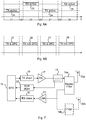
- Fig 6A is a schematic diagram illustrating how the different modes are employed over time in the network node 1 of Fig 1 , when the TOR receiver operates in two different modes, e.g. as shown in the embodiment of Figs 5A-B .
- transmission is active 24 and the coarse mode is used and pre-scan of LTE-U frequencies can be done.
- reception is active 25 and the TOR is used in accurate mode to perform accurate measurement of the LTE-U channel, i.e. using the LNA 23 of Figs 5A-B .
- accurate measurements are only performed for frequencies which have had signal level below threshold level, as determined from the coarse mode. In other words, only frequencies which have been found in the coarse mode to have a signal level (from interference) below a threshold are candidates for which accurate measurements are worth obtaining. Alternatively or additionally, the transmission frequencies which were used in a previous receive time slot are scanned.
- both the transmit time slot 27 and the receive time slot 28 can be used to evaluate frequencies to find a good frequency to use for a channel for LTE-U within the unlicensed frequency band. This allows more time to evaluate frequencies leading to a better evaluation than if only the transmit time slot 27 is used or if only the receive time slot 28 is used.
- a decision on what frequency band, if any, to use can thus be performed in the time frame of one transmit time slot and one receive time slot, i.e. between each instance of a transmit time slot. In this way, switching between different TOR modes can be done during the time gap 29 in between transmit and receive time slots.
- Fig 6B is a schematic diagram illustrating how the different modes are employed over time in the network node 1 of Fig 1 in an alternative embodiment, when the TOR receiver operates in two different modes, e.g. as shown in the embodiment of Figs 5A-B .
- transmission linearization time slots (Tx & DPD) 37 transmission is active and the TOR receiver is used for DPD purposes.
- TOR is used to detect interference signals in the coarse mode and pre-scan of LTE-U frequencies can be done.
- the TOR is effectively operational at (at least) two different frequencies during the transmission linearization time slot 37: at the transmission frequency and at the (one or more) interference frequency.
- transmission is active and TOR receiver is tuned to interference frequency.
- the TOR receiver is used in accurate mode to perform accurate measurement of the LTE-U channel, i.e. using the LNA 23.
- the signal path where the measured interference signal is coming to LNA 23 may be selected dynamically for example which antenna is used for the purpose.
- Fig 7 is a schematic diagram illustrating some components of a network node 1 in an embodiment where both UL and DL is employed for LTE-U.
- a receiver (RX) chain 32 for the UL
- the LNA 23 is provided between the filter 19a (which is here a duplex filter since both reception and transmission occurs in the network node) and the RX chain 32.
- the filter 19a which is here a duplex filter since both reception and transmission occurs in the network node
- the two modes are employed as illustrated in Fig 6 and described above.
- the TOR receiver in the TOR chain 22 is still used for the coarse mode (in the transmit time slot 27 of Fig 6 ), but the regular receiver 32 is used for the accurate mode (in the receive time slot 28 of Fig 6 ).
- the coarse mode no LNA is used and the TOR receiver is used as for the embodiments described above with reference to Figs 5A-B .
- the accurate mode the LNA 23 and the receive chain 32 (also used for regular UL signals) is used (instead of the LNA and TOR chain as described above with reference to Figs 5A-B ).
- the network node 1 may include a second antenna 20b which connected to a second filter 19b which is further connected to the LNA 23 and thus the RX chain 32.
- the filter 19a is not a duplex filter.
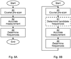
- Figs 8A-B are flow charts illustrating embodiments of methods for determining an unlicensed frequency band to use. More specifically, the method is used for determining a centre frequency in an unlicensed frequency band to use for downlink communication in a cellular network.
- a coarse pre-scan is performed when the network node is in a transmit time slot, yielding respective coarse measurement of signal levels for a plurality of frequencies in the unlicensed frequency band.
- the coarse pre-scan can be performed using the TOR receiver. This corresponds to the first dynamic range 13a of Fig 4 , performed in the transmit time slot 27 of Fig 6 or in the Tx and DPD time slot 37 of Fig 6B .
- an accurate measurement is performed when the network node is in a receive time slot, yielding respective accurate measurements of signal levels for a plurality of frequencies in the unlicensed frequency band. This corresponds to the second dynamic range 13b of Fig 4 , performed in the receive time slot 28 of Fig 6 or in the Tx w/o DPD time slot 38 of Fig 6B .
- the accurate measurement (in step 42) is performed using the TOR receiver with a first configurable gain, while the coarse pre-scan is then performed (in step 40) using the TOR with a second configurable gain.
- the first configurable gain is higher than the second configurable gain, to improve the accuracy for the accurate measurement while allowing higher signal levels for the course measurements (see dynamic ranges 13a-b of Fig 4 ).
- the accurate measurement (in step 42) is performed using the TOR receiver and the LNA, while the coarse pre-scan is performed (in step 40) using the TOR without the LNA.
- the accurate measurement is performed using a receive chain of the network node arranged to be used also for receiving uplink communication (in the unlicensed frequency band(s)).
- a determine frequencies step 44 at least one frequency is determined to be used as a centre frequency for a downlink communication channel in the unlicensed frequency band.
- the centre frequency is selected such that frequencies for which the coarse measurement and/or the accurate measurements indicate a high signal level are avoided. This is done since the high signal levels indicate interference which may have a negative effect for the downlink communication channel.
- Each centre frequency is in a centre of a frequency band used for a respective downlink communication channel.
- the frequencies used in the measurements in the course pre-scan step 40 and/or the accurate measurement step 42 are centre frequencies of potential downlink communication channels. However, this does not need to be the case as long as the measurements are within frequencies used for each downlink communication channel.
- the determine frequencies step 44 is performed in the same receive time slot in which the accurate measurement step 42 is performed. In this way, the whole process can be performed during one set of a transmit time slot and a receive time slot, allowing fast adaption to changing radio conditions. Also, by using the different dynamic ranges for the receive time slot and the transmit time slot, evaluation of interference can be performed in both types of time slots, which increases ability to evaluate frequencies in the number of frequencies evaluated and/or the accuracy of such evaluation.
- a set of candidate frequencies are determined to be the frequencies for which the course measurements of signal levels are lower than a threshold level.
- the accurate measurement step 42 is only performed for the set of candidate frequencies.
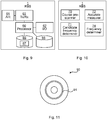
- Fig 9 is a schematic diagram showing some components of the network node 1 of Fig 1 .
- a processor 60 is provided using any combination of one or more of a suitable central processing unit (CPU), multiprocessor, microcontroller, digital signal processor (DSP), application specific integrated circuit etc., capable of executing software instructions 67 stored in a memory 65, which can thus be a computer program product.
- the processor 60 can be configured to execute the method described with reference to Figs 8A-B above.
- the memory 65 can be any combination of read and write memory (RAM) and read only memory (ROM).
- the memory 65 also comprises persistent storage, which, for example, can be any single one or combination of magnetic memory, optical memory, solid state memory or even remotely mounted memory.
- a data memory 66 is also provided for reading and/or storing data during execution of software instructions in the processor 60.
- the data memory 66 can be any combination of read and write memory (RAM) and read only memory (ROM).
- the network node 1 further comprises an I/O interface 62 for communicating with other external entities.
- the I/O interface 62 also includes a user interface.
- the network node 1 also comprises one or more transceivers 63, comprising analogue and digital components, and a suitable number of antennas 61 for wireless communication with wireless devices as shown in Fig 1 .
- Fig 10 is a schematic diagram showing functional modules of the network node 1 of Fig 9 according to one embodiment.
- the modules are implemented using software instructions such as a computer program executing in the network node 1.
- the modules correspond to the steps in the methods illustrated in Figs 8A-B .
- a course pre-scanner module 70 is arranged to perform a coarse pre-scan when the network node is in a transmit time slot, yielding a coarse measurement of signal levels for a plurality of frequencies. This module corresponds to the course pre-scan step 40 of Figs 8A-B .
- a candidate frequency determiner 71 is arranged to determine a set of candidate frequencies as the frequencies for which the course measurements of signal levels are lower than a threshold level. This module corresponds to the determine candidate frequencies step 41 of Fig 8B .
- An accurate measurer 72 is arranged to perform an accurate measurement when the network node is in a receive time slot, yielding an accurate measurement of signal levels for a plurality of frequencies. This module corresponds to the accurate measurement step 42 of Figs 8A-B .
- a frequency determiner 74 is arranged to determine at least one frequency to use as a centre frequency for a downlink communication channel. This module corresponds to the determine frequencies step 44 of Figs 8A-B .
- Fig 11 shows one example of a computer program product comprising computer readable means.
- a computer program 91 can be stored, which computer program can cause a processor to execute a method according to embodiments described herein.
- the computer program product is an optical disc, such as a CD (compact disc) or a DVD (digital versatile disc) or a Blu-Ray disc.
- the computer program product could also be embodied in a memory of a device, such as the computer program product 65 of Fig 9 .
- the computer program 91 is here schematically shown as a track on the depicted optical disk, the computer program can be stored in any way which is suitable for the computer program product, such as a removable solid state memory, e.g. a Universal Serial Bus (USB) drive.
- USB Universal Serial Bus
Landscapes
- Engineering & Computer Science (AREA)
- Computer Networks & Wireless Communication (AREA)
- Signal Processing (AREA)
- Quality & Reliability (AREA)
- Mobile Radio Communication Systems (AREA)
Claims (14)
- Verfahren zum Bestimmen einer Mittenfrequenz in einem unlizenzierten Frequenzband zur Verwendung für die Downlink-(4b)-Kommunikation in einem zellularen Netz (8), wobei das Verfahren in einem Netzknoten (1) durchgeführt wird und die Schritte umfasst:Durchführen (40) einer groben Vorabtastung mit einem ersten dynamischen Bereich (13a) für hohe Signalpegel, wenn sich der Netzknoten in einem Übertragungszeitschlitz (27) befindet, was eine entsprechende grobe Messung von Signalpegeln für eine Vielzahl von Frequenzen im unlizenzierten Frequenzband ergibt;Durchführen (42) einer Messung mit einem zweiten dynamischen Bereich (13b) für niedrige Signalpegel, wenn sich der Netzknoten in einem Empfangszeitschlitz (28) befindet, was eine entsprechende genaue Messung von Signalpegeln für eine Vielzahl von Frequenzen im unlizenzierten Frequenzband ergibt, wobei sich der zweite dynamische Bereich (13b) von dem ersten dynamischen Bereich (13a) unterscheidet; undBestimmen (44) mindestens einer Frequenz zur Verwendung als Mittenfrequenz für einen Downlink-(4b)-Kommunikationskanal in dem unlizenzierten Frequenzband, wobei die Mittenfrequenz so gewählt ist, dass Frequenzen, für die die grobe Messung und die genaue Messung Störungen für den Downlink-(4b)-Kommunikationskanal angeben, vermieden werden.
- Verfahren nach Anspruch 1, wobei der Schritt des Durchführens (40) einer groben Vorabtastung unter Verwendung eines Sender-Beobachtungsempfängers, TOR, durchgeführt wird.
- Verfahren nach Anspruch 1 oder 2, wobei der Schritt des Durchführens (42) der Messung zum Erzielen einer genauen Messung unter Verwendung des TOR-Empfängers mit einer ersten konfigurierbaren Verstärkung durchgeführt wird; und wobei der Schritt des Durchführens (40) der groben Vorabtastung unter Verwendung des TOR mit einer zweiten konfigurierbaren Verstärkung durchgeführt wird, wobei die erste konfigurierbare Verstärkung höher als die zweite konfigurierbare Verstärkung ist.
- Verfahren nach Anspruch 1 oder 2, wobei der Schritt des Durchführens (42) der Messung zum Erzielen einer genauen Messung unter Verwendung des TOR-Empfängers und eines rauscharmen Verstärkers durchgeführt wird; und wobei der Schritt des Durchführens (40) der groben Vorabtastung unter Verwendung des TOR ohne den rauscharmen Verstärker durchgeführt wird.
- Verfahren nach Anspruch 1 oder 2, wobei der Schritt des Durchführens (42) der Messung zum Erzielen einer genauen Messung unter Verwendung einer Empfangskette des Netzknotens durchgeführt wird, die so angeordnet ist, dass sie auch zum Empfangen von Uplink-Kommunikation verwendet wird.
- Verfahren nach einem der vorhergehenden Ansprüche, ferner umfassend einen Schritt des:Bestimmens (41) eines Satzes von Kandidatenfrequenzen als die Frequenzen, bei denen die Verlaufsmessungen der Signalpegel unter einem Schwellenwert liegen;und wobei der Schritt des Durchführens (42) der Messung zum Erzielen einer genauen Messung nur für den Satz von Kandidatenfrequenzen durchgeführt wird.
- Verfahren nach einem der vorstehenden Ansprüche, bei dem der Schritt des Bestimmens (44) von mindestens einer Frequenz im gleichen Empfangszeitschlitz durchgeführt wird, in dem der Schritt des Durchführens (42) der Messung zum Erzielen einer genauen Messung durchgeführt wird.
- Netzknoten (1) zum Bestimmen einer Mittenfrequenz in einem unlizenzierten Frequenzband zur Verwendung für die Downlink-(4b)-Kommunikation in einem zellularen Netz (8), wobei der Netzknoten (1) umfasst:einen Prozessor (60); undeinen Speicher (65), der Anweisungen (67) speichert, die, wenn sie vom Prozessor ausgeführt werden, den Netzknoten (1) veranlassen zum:Durchführen einer groben Vorabtastung mit einem ersten dynamischen Bereich (13a) für hohe Signalpegel, wenn sich der Netzknoten in einem Übertragungszeitschlitz (27) befindet, was eine grobe Messung der Signalpegel für eine Vielzahl von Frequenzen im unlizenzierten Frequenzband ergibt;Durchführen einer Messung mit einem zweiten dynamischen Bereich (13b) für niedrige Signalpegel, wenn sich der Netzknoten in einem Empfangszeitschlitz (28) befindet, was eine genaue Messung von Signalpegeln für eine Vielzahl von Frequenzen im unlizenzierten Frequenzband ergibt, wobei sich der zweite dynamische Bereich (13b) von dem ersten dynamischen Bereich (13a) unterscheidet; undBestimmen mindestens einer Frequenz, die als Mittenfrequenz für einen Downlink-(4b)-Kommunikationskanal im unlizenzierten Frequenzband zu verwenden ist, wobei die Mittenfrequenz so gewählt wird, dass Frequenzen, für die die grobe Messung und die genaue Messung Störungen für den Downlink-(4b)-Kommunikationskanal angeben, vermieden werden.
- Netzknoten (1) nach Anspruch 8, wobei die Anweisungen zum Durchführen der groben Vorabtastung mit Hilfe eines Sender-Beobachtungsempfängers, TOR, ausgeführt werden.
- Netzknoten (1) nach Anspruch 8 oder 9, wobei die Anweisungen zum Durchführen der Messung, um die genaue Messung zu erhalten, unter Verwendung des TOR-Empfängers mit einer ersten konfigurierbaren Verstärkung durchgeführt werden; und wobei die Anweisungen zum Durchführen der groben Vorabtastung unter Verwendung des TOR mit einer zweiten konfigurierbaren Verstärkung ausgeführt werden, wobei die erste konfigurierbare Verstärkung höher als die zweite konfigurierbare Verstärkung ist.
- Netzknoten (1) nach Anspruch 8 oder 9, wobei die Anweisungen zum Durchführen der Messung, um die genaue Messung zu erhalten, unter Verwendung des TOR-Empfängers und eines rauscharmen Verstärkers durchgeführt werden; und wobei die Anweisungen zum Durchführen der groben Vorabtastung mit Hilfe des TOR ohne den rauscharmen Verstärker ausgeführt werden.
- Netzknoten (1) nach Anspruch 8 oder 9, wobei die Anweisungen zum Durchführen der Messung, um die genaue Messung zu erhalten, unter Verwendung einer Empfangskette des Netzknotens ausgeführt werden, die auch für den Empfang der Uplink-Kommunikation verwendet wird.
- Computerprogramm (91) zum Bestimmen einer Mittenfrequenz in einem unlizenzierten Frequenzband zur Verwendung für eine Downlink-(4b)-Kommunikation in einem zellularen Netz, wobei das Computerprogramm Computerprogrammcode umfasst, der, wenn er auf einem Netzknoten (1) ausgeführt wird, den Netzknoten (1) veranlasst, das Verfahren nach einem der Ansprüche 1 bis 7 durchzuführen.
- Computerprogrammprodukt (90), umfassend ein Computerprogramm nach Anspruch 13 und ein computerlesbares Mittel, auf dem das Computerprogramm gespeichert ist.
Applications Claiming Priority (2)
| Application Number | Priority Date | Filing Date | Title |
|---|---|---|---|
| EP14187220 | 2014-09-30 | ||
| PCT/SE2014/051284 WO2016053157A1 (en) | 2014-09-30 | 2014-10-30 | Determining a centre frequency in an unlicensed frequency band to use |
Publications (2)
| Publication Number | Publication Date |
|---|---|
| EP3202199A1 EP3202199A1 (de) | 2017-08-09 |
| EP3202199B1 true EP3202199B1 (de) | 2020-03-25 |
Family
ID=51661909
Family Applications (1)
| Application Number | Title | Priority Date | Filing Date |
|---|---|---|---|
| EP14799909.8A Active EP3202199B1 (de) | 2014-09-30 | 2014-10-30 | Bestimmung einer mittenfrequenz in einem unlizenzierten frequenzband zur verwendung |
Country Status (3)
| Country | Link |
|---|---|
| US (1) | US10278089B2 (de) |
| EP (1) | EP3202199B1 (de) |
| WO (1) | WO2016053157A1 (de) |
Families Citing this family (6)
| Publication number | Priority date | Publication date | Assignee | Title |
|---|---|---|---|---|
| US10517021B2 (en) | 2016-06-30 | 2019-12-24 | Evolve Cellular Inc. | Long term evolution-primary WiFi (LTE-PW) |
| US11159187B2 (en) * | 2018-02-26 | 2021-10-26 | Parallel Wireless, Inc. | Microcomponent massive MIMO arrays |
| US11528068B2 (en) | 2018-07-30 | 2022-12-13 | Innophase, Inc. | System and method for massive MIMO communication |
| WO2020093005A1 (en) | 2018-11-01 | 2020-05-07 | Innophase, Inc. | Reconfigurable phase array |
| EP4052335B1 (de) | 2019-10-28 | 2025-07-30 | Innophase, Inc. | Massive-mimo-antennenarray mit mehreren frequenzbändern |
| CN111147412B (zh) * | 2019-12-25 | 2021-11-09 | 三维通信股份有限公司 | 预失真处理装置、信号传输系统和预失真处理方法 |
Family Cites Families (7)
| Publication number | Priority date | Publication date | Assignee | Title |
|---|---|---|---|---|
| JP2009284044A (ja) * | 2008-05-20 | 2009-12-03 | Fujitsu Ltd | 無線送信装置 |
| US8478282B2 (en) * | 2008-10-20 | 2013-07-02 | Centurylink Intellectual Property Llc | Method and apparatus for managing frequencies used by devices |
| US8861452B2 (en) * | 2010-08-16 | 2014-10-14 | Qualcomm Incorporated | Method and apparatus for use of licensed spectrum for control channels in cognitive radio communications |
| WO2012026857A1 (en) | 2010-08-26 | 2012-03-01 | Telefonaktiebolaget L M Ericsson (Publ) | Method and network node in a communications system |
| US20120282942A1 (en) * | 2011-05-02 | 2012-11-08 | Nokia Siemens Networks Oy | Methods, apparatuses and computer program products for configuring frequency aggregation |
| WO2012173434A2 (ko) | 2011-06-15 | 2012-12-20 | 엘지전자 주식회사 | 무선 접속 시스템에서 무선 자원 할당 방법 및 이를 위한 장치 |
| US8766712B2 (en) * | 2012-05-04 | 2014-07-01 | Analog Devices, Inc. | Quality factor tuning for LC circuits |
-
2014
- 2014-10-30 EP EP14799909.8A patent/EP3202199B1/de active Active
- 2014-10-30 US US15/510,226 patent/US10278089B2/en active Active
- 2014-10-30 WO PCT/SE2014/051284 patent/WO2016053157A1/en not_active Ceased
Non-Patent Citations (1)
| Title |
|---|
| None * |
Also Published As
| Publication number | Publication date |
|---|---|
| EP3202199A1 (de) | 2017-08-09 |
| WO2016053157A1 (en) | 2016-04-07 |
| US10278089B2 (en) | 2019-04-30 |
| US20170289833A1 (en) | 2017-10-05 |
Similar Documents
| Publication | Publication Date | Title |
|---|---|---|
| CN109565320B (zh) | 有效波束和候选波束的波束细化 | |
| US11510077B2 (en) | Method and user equipment for performing measurement by using multiple reception beams | |
| CN109314945B (zh) | 波束成形通信中的定位 | |
| KR102710145B1 (ko) | 동기화 래스터 및 채널 래스터의 디커플링 | |
| JP7022799B2 (ja) | ワイヤレス通信における基準信号リソース捜索技法 | |
| EP3202199B1 (de) | Bestimmung einer mittenfrequenz in einem unlizenzierten frequenzband zur verwendung | |
| US8873435B2 (en) | Short random access channel (RACH) disabling in TDD-LTE | |
| JP6215226B2 (ja) | より少ない数の受信チェーンを使用した受信アンテナ選択/受信アンテナの組合せ | |
| CN105284143B (zh) | 参考信号的检测方法、接收方法、用户设备和基站 | |
| US9692494B2 (en) | Dynamic switching between wireless multiple access schemes | |
| US10785009B2 (en) | Reference signal transmission method and related device and system | |
| US20190044601A1 (en) | Device and method of using brrs configuration | |
| CN103299708A (zh) | 用户装置以及测定方法 | |
| WO2019140653A1 (en) | Methods, devices and computer readable medium for new radio management measurement | |
| JP7285324B2 (ja) | 端末、通信システム、及び通信方法 | |
| WO2019190672A1 (en) | Methods and devices for radio resource allocation | |
| US10560237B2 (en) | Cell-specific reference signal transmissions for evolved machine type communication | |
| US20170353955A1 (en) | Resource management | |
| JP2017135620A (ja) | 通信中継装置、通信中継システム、方法及びプログラム | |
| US10701731B2 (en) | Determining whether to transmit data on a candidate radio channel | |
| CN117015935A (zh) | 用于多trp ul传输的方法和装置 | |
| KR100915226B1 (ko) | 랜덤액세스 프리앰블 송신 방법 |
Legal Events
| Date | Code | Title | Description |
|---|---|---|---|
| STAA | Information on the status of an ep patent application or granted ep patent |
Free format text: STATUS: THE INTERNATIONAL PUBLICATION HAS BEEN MADE |
|
| PUAI | Public reference made under article 153(3) epc to a published international application that has entered the european phase |
Free format text: ORIGINAL CODE: 0009012 |
|
| STAA | Information on the status of an ep patent application or granted ep patent |
Free format text: STATUS: REQUEST FOR EXAMINATION WAS MADE |
|
| 17P | Request for examination filed |
Effective date: 20170407 |
|
| AK | Designated contracting states |
Kind code of ref document: A1 Designated state(s): AL AT BE BG CH CY CZ DE DK EE ES FI FR GB GR HR HU IE IS IT LI LT LU LV MC MK MT NL NO PL PT RO RS SE SI SK SM TR |
|
| AX | Request for extension of the european patent |
Extension state: BA ME |
|
| DAX | Request for extension of the european patent (deleted) | ||
| STAA | Information on the status of an ep patent application or granted ep patent |
Free format text: STATUS: EXAMINATION IS IN PROGRESS |
|
| 17Q | First examination report despatched |
Effective date: 20180528 |
|
| REG | Reference to a national code |
Ref country code: DE Ref legal event code: R079 Ref document number: 602014062890 Country of ref document: DE Free format text: PREVIOUS MAIN CLASS: H04W0072040000 Ipc: H04W0024020000 |
|
| GRAP | Despatch of communication of intention to grant a patent |
Free format text: ORIGINAL CODE: EPIDOSNIGR1 |
|
| STAA | Information on the status of an ep patent application or granted ep patent |
Free format text: STATUS: GRANT OF PATENT IS INTENDED |
|
| RIC1 | Information provided on ipc code assigned before grant |
Ipc: H04W 24/02 20090101AFI20200107BHEP Ipc: H04W 16/14 20090101ALI20200107BHEP Ipc: H04W 72/00 20090101ALI20200107BHEP Ipc: H04W 24/00 20090101ALI20200107BHEP |
|
| GRAS | Grant fee paid |
Free format text: ORIGINAL CODE: EPIDOSNIGR3 |
|
| INTG | Intention to grant announced |
Effective date: 20200120 |
|
| GRAA | (expected) grant |
Free format text: ORIGINAL CODE: 0009210 |
|
| STAA | Information on the status of an ep patent application or granted ep patent |
Free format text: STATUS: THE PATENT HAS BEEN GRANTED |
|
| AK | Designated contracting states |
Kind code of ref document: B1 Designated state(s): AL AT BE BG CH CY CZ DE DK EE ES FI FR GB GR HR HU IE IS IT LI LT LU LV MC MK MT NL NO PL PT RO RS SE SI SK SM TR |
|
| REG | Reference to a national code |
Ref country code: GB Ref legal event code: FG4D |
|
| REG | Reference to a national code |
Ref country code: DE Ref legal event code: R096 Ref document number: 602014062890 Country of ref document: DE |
|
| REG | Reference to a national code |
Ref country code: AT Ref legal event code: REF Ref document number: 1250014 Country of ref document: AT Kind code of ref document: T Effective date: 20200415 Ref country code: IE Ref legal event code: FG4D |
|
| PG25 | Lapsed in a contracting state [announced via postgrant information from national office to epo] |
Ref country code: RS Free format text: LAPSE BECAUSE OF FAILURE TO SUBMIT A TRANSLATION OF THE DESCRIPTION OR TO PAY THE FEE WITHIN THE PRESCRIBED TIME-LIMIT Effective date: 20200325 Ref country code: FI Free format text: LAPSE BECAUSE OF FAILURE TO SUBMIT A TRANSLATION OF THE DESCRIPTION OR TO PAY THE FEE WITHIN THE PRESCRIBED TIME-LIMIT Effective date: 20200325 Ref country code: NO Free format text: LAPSE BECAUSE OF FAILURE TO SUBMIT A TRANSLATION OF THE DESCRIPTION OR TO PAY THE FEE WITHIN THE PRESCRIBED TIME-LIMIT Effective date: 20200625 |
|
| PG25 | Lapsed in a contracting state [announced via postgrant information from national office to epo] |
Ref country code: HR Free format text: LAPSE BECAUSE OF FAILURE TO SUBMIT A TRANSLATION OF THE DESCRIPTION OR TO PAY THE FEE WITHIN THE PRESCRIBED TIME-LIMIT Effective date: 20200325 Ref country code: GR Free format text: LAPSE BECAUSE OF FAILURE TO SUBMIT A TRANSLATION OF THE DESCRIPTION OR TO PAY THE FEE WITHIN THE PRESCRIBED TIME-LIMIT Effective date: 20200626 Ref country code: LV Free format text: LAPSE BECAUSE OF FAILURE TO SUBMIT A TRANSLATION OF THE DESCRIPTION OR TO PAY THE FEE WITHIN THE PRESCRIBED TIME-LIMIT Effective date: 20200325 Ref country code: SE Free format text: LAPSE BECAUSE OF FAILURE TO SUBMIT A TRANSLATION OF THE DESCRIPTION OR TO PAY THE FEE WITHIN THE PRESCRIBED TIME-LIMIT Effective date: 20200325 Ref country code: BG Free format text: LAPSE BECAUSE OF FAILURE TO SUBMIT A TRANSLATION OF THE DESCRIPTION OR TO PAY THE FEE WITHIN THE PRESCRIBED TIME-LIMIT Effective date: 20200625 |
|
| REG | Reference to a national code |
Ref country code: NL Ref legal event code: MP Effective date: 20200325 |
|
| REG | Reference to a national code |
Ref country code: LT Ref legal event code: MG4D |
|
| PG25 | Lapsed in a contracting state [announced via postgrant information from national office to epo] |
Ref country code: NL Free format text: LAPSE BECAUSE OF FAILURE TO SUBMIT A TRANSLATION OF THE DESCRIPTION OR TO PAY THE FEE WITHIN THE PRESCRIBED TIME-LIMIT Effective date: 20200325 |
|
| PG25 | Lapsed in a contracting state [announced via postgrant information from national office to epo] |
Ref country code: RO Free format text: LAPSE BECAUSE OF FAILURE TO SUBMIT A TRANSLATION OF THE DESCRIPTION OR TO PAY THE FEE WITHIN THE PRESCRIBED TIME-LIMIT Effective date: 20200325 Ref country code: SK Free format text: LAPSE BECAUSE OF FAILURE TO SUBMIT A TRANSLATION OF THE DESCRIPTION OR TO PAY THE FEE WITHIN THE PRESCRIBED TIME-LIMIT Effective date: 20200325 Ref country code: IS Free format text: LAPSE BECAUSE OF FAILURE TO SUBMIT A TRANSLATION OF THE DESCRIPTION OR TO PAY THE FEE WITHIN THE PRESCRIBED TIME-LIMIT Effective date: 20200725 Ref country code: CZ Free format text: LAPSE BECAUSE OF FAILURE TO SUBMIT A TRANSLATION OF THE DESCRIPTION OR TO PAY THE FEE WITHIN THE PRESCRIBED TIME-LIMIT Effective date: 20200325 Ref country code: PT Free format text: LAPSE BECAUSE OF FAILURE TO SUBMIT A TRANSLATION OF THE DESCRIPTION OR TO PAY THE FEE WITHIN THE PRESCRIBED TIME-LIMIT Effective date: 20200818 Ref country code: LT Free format text: LAPSE BECAUSE OF FAILURE TO SUBMIT A TRANSLATION OF THE DESCRIPTION OR TO PAY THE FEE WITHIN THE PRESCRIBED TIME-LIMIT Effective date: 20200325 Ref country code: SM Free format text: LAPSE BECAUSE OF FAILURE TO SUBMIT A TRANSLATION OF THE DESCRIPTION OR TO PAY THE FEE WITHIN THE PRESCRIBED TIME-LIMIT Effective date: 20200325 Ref country code: EE Free format text: LAPSE BECAUSE OF FAILURE TO SUBMIT A TRANSLATION OF THE DESCRIPTION OR TO PAY THE FEE WITHIN THE PRESCRIBED TIME-LIMIT Effective date: 20200325 |
|
| REG | Reference to a national code |
Ref country code: AT Ref legal event code: MK05 Ref document number: 1250014 Country of ref document: AT Kind code of ref document: T Effective date: 20200325 |
|
| REG | Reference to a national code |
Ref country code: DE Ref legal event code: R097 Ref document number: 602014062890 Country of ref document: DE |
|
| PG25 | Lapsed in a contracting state [announced via postgrant information from national office to epo] |
Ref country code: AT Free format text: LAPSE BECAUSE OF FAILURE TO SUBMIT A TRANSLATION OF THE DESCRIPTION OR TO PAY THE FEE WITHIN THE PRESCRIBED TIME-LIMIT Effective date: 20200325 Ref country code: DK Free format text: LAPSE BECAUSE OF FAILURE TO SUBMIT A TRANSLATION OF THE DESCRIPTION OR TO PAY THE FEE WITHIN THE PRESCRIBED TIME-LIMIT Effective date: 20200325 Ref country code: ES Free format text: LAPSE BECAUSE OF FAILURE TO SUBMIT A TRANSLATION OF THE DESCRIPTION OR TO PAY THE FEE WITHIN THE PRESCRIBED TIME-LIMIT Effective date: 20200325 Ref country code: IT Free format text: LAPSE BECAUSE OF FAILURE TO SUBMIT A TRANSLATION OF THE DESCRIPTION OR TO PAY THE FEE WITHIN THE PRESCRIBED TIME-LIMIT Effective date: 20200325 |
|
| PLBE | No opposition filed within time limit |
Free format text: ORIGINAL CODE: 0009261 |
|
| STAA | Information on the status of an ep patent application or granted ep patent |
Free format text: STATUS: NO OPPOSITION FILED WITHIN TIME LIMIT |
|
| PG25 | Lapsed in a contracting state [announced via postgrant information from national office to epo] |
Ref country code: PL Free format text: LAPSE BECAUSE OF FAILURE TO SUBMIT A TRANSLATION OF THE DESCRIPTION OR TO PAY THE FEE WITHIN THE PRESCRIBED TIME-LIMIT Effective date: 20200325 |
|
| 26N | No opposition filed |
Effective date: 20210112 |
|
| PG25 | Lapsed in a contracting state [announced via postgrant information from national office to epo] |
Ref country code: SI Free format text: LAPSE BECAUSE OF FAILURE TO SUBMIT A TRANSLATION OF THE DESCRIPTION OR TO PAY THE FEE WITHIN THE PRESCRIBED TIME-LIMIT Effective date: 20200325 |
|
| REG | Reference to a national code |
Ref country code: CH Ref legal event code: PL |
|
| PG25 | Lapsed in a contracting state [announced via postgrant information from national office to epo] |
Ref country code: MC Free format text: LAPSE BECAUSE OF FAILURE TO SUBMIT A TRANSLATION OF THE DESCRIPTION OR TO PAY THE FEE WITHIN THE PRESCRIBED TIME-LIMIT Effective date: 20200325 Ref country code: LU Free format text: LAPSE BECAUSE OF NON-PAYMENT OF DUE FEES Effective date: 20201030 |
|
| REG | Reference to a national code |
Ref country code: BE Ref legal event code: MM Effective date: 20201031 |
|
| PG25 | Lapsed in a contracting state [announced via postgrant information from national office to epo] |
Ref country code: FR Free format text: LAPSE BECAUSE OF NON-PAYMENT OF DUE FEES Effective date: 20201031 |
|
| PG25 | Lapsed in a contracting state [announced via postgrant information from national office to epo] |
Ref country code: CH Free format text: LAPSE BECAUSE OF NON-PAYMENT OF DUE FEES Effective date: 20201031 Ref country code: BE Free format text: LAPSE BECAUSE OF NON-PAYMENT OF DUE FEES Effective date: 20201031 Ref country code: LI Free format text: LAPSE BECAUSE OF NON-PAYMENT OF DUE FEES Effective date: 20201031 |
|
| PG25 | Lapsed in a contracting state [announced via postgrant information from national office to epo] |
Ref country code: IE Free format text: LAPSE BECAUSE OF NON-PAYMENT OF DUE FEES Effective date: 20201030 |
|
| PG25 | Lapsed in a contracting state [announced via postgrant information from national office to epo] |
Ref country code: TR Free format text: LAPSE BECAUSE OF FAILURE TO SUBMIT A TRANSLATION OF THE DESCRIPTION OR TO PAY THE FEE WITHIN THE PRESCRIBED TIME-LIMIT Effective date: 20200325 Ref country code: MT Free format text: LAPSE BECAUSE OF FAILURE TO SUBMIT A TRANSLATION OF THE DESCRIPTION OR TO PAY THE FEE WITHIN THE PRESCRIBED TIME-LIMIT Effective date: 20200325 Ref country code: CY Free format text: LAPSE BECAUSE OF FAILURE TO SUBMIT A TRANSLATION OF THE DESCRIPTION OR TO PAY THE FEE WITHIN THE PRESCRIBED TIME-LIMIT Effective date: 20200325 |
|
| PG25 | Lapsed in a contracting state [announced via postgrant information from national office to epo] |
Ref country code: MK Free format text: LAPSE BECAUSE OF FAILURE TO SUBMIT A TRANSLATION OF THE DESCRIPTION OR TO PAY THE FEE WITHIN THE PRESCRIBED TIME-LIMIT Effective date: 20200325 Ref country code: AL Free format text: LAPSE BECAUSE OF FAILURE TO SUBMIT A TRANSLATION OF THE DESCRIPTION OR TO PAY THE FEE WITHIN THE PRESCRIBED TIME-LIMIT Effective date: 20200325 |
|
| PGFP | Annual fee paid to national office [announced via postgrant information from national office to epo] |
Ref country code: DE Payment date: 20250919 Year of fee payment: 12 |
|
| PGFP | Annual fee paid to national office [announced via postgrant information from national office to epo] |
Ref country code: GB Payment date: 20251024 Year of fee payment: 12 |