EP3202242A1 - Attelage permettant de relier un outil à un véhicule - Google Patents
Attelage permettant de relier un outil à un véhicule Download PDFInfo
- Publication number
- EP3202242A1 EP3202242A1 EP17153158.5A EP17153158A EP3202242A1 EP 3202242 A1 EP3202242 A1 EP 3202242A1 EP 17153158 A EP17153158 A EP 17153158A EP 3202242 A1 EP3202242 A1 EP 3202242A1
- Authority
- EP
- European Patent Office
- Prior art keywords
- frame
- pair
- hitch
- members
- attachment
- Prior art date
- Legal status (The legal status is an assumption and is not a legal conclusion. Google has not performed a legal analysis and makes no representation as to the accuracy of the status listed.)
- Granted
Links
Images


Classifications
-
- A—HUMAN NECESSITIES
- A01—AGRICULTURE; FORESTRY; ANIMAL HUSBANDRY; HUNTING; TRAPPING; FISHING
- A01B—SOIL WORKING IN AGRICULTURE OR FORESTRY; PARTS, DETAILS, OR ACCESSORIES OF AGRICULTURAL MACHINES OR IMPLEMENTS, IN GENERAL
- A01B59/00—Devices specially adapted for connection between animals or tractors and agricultural machines or implements
- A01B59/04—Devices specially adapted for connection between animals or tractors and agricultural machines or implements for machines pulled or pushed by a tractor
- A01B59/042—Devices specially adapted for connection between animals or tractors and agricultural machines or implements for machines pulled or pushed by a tractor having pulling means arranged on the rear part of the tractor
-
- A—HUMAN NECESSITIES
- A01—AGRICULTURE; FORESTRY; ANIMAL HUSBANDRY; HUNTING; TRAPPING; FISHING
- A01B—SOIL WORKING IN AGRICULTURE OR FORESTRY; PARTS, DETAILS, OR ACCESSORIES OF AGRICULTURAL MACHINES OR IMPLEMENTS, IN GENERAL
- A01B59/00—Devices specially adapted for connection between animals or tractors and agricultural machines or implements
- A01B59/06—Devices specially adapted for connection between animals or tractors and agricultural machines or implements for machines mounted on tractors
- A01B59/061—Devices specially adapted for connection between animals or tractors and agricultural machines or implements for machines mounted on tractors specially adapted for enabling connection or disconnection controlled from the driver's seat
- A01B59/062—Devices specially adapted for connection between animals or tractors and agricultural machines or implements for machines mounted on tractors specially adapted for enabling connection or disconnection controlled from the driver's seat the connection comprising a rigid interface frame on the tractor
Definitions
- the present disclosure relates to the field of hitches allowing connection of an implement to a vehicle, and more particularly to a hitch designed for facilitating the connection of the hitch to the vehicle.
- a system specifically designed for connecting an implement to a vehicle is generally used.
- the system may consist of a three-point hitch comprising three links for connecting the implement to the vehicle.
- the system may consist of a four-point hitch comprising four links for connecting the implement to the vehicle.
- a common design for a four-point hitch comprises two lower links and two upper links, each link being connected at one end with the implement and at the other end with the vehicle.
- the present disclosure relates to a hitch for connecting an implement to a vehicle.
- the hitch comprises a first frame for attachment to the vehicle, a second frame for attachment to the implement, and a pair of locking mechanisms.
- the first frame comprises a pair of substantially L-shaped parallel elongated members fixedly connected together.
- Each of the elongated members comprises a first extremity for attaching to the vehicle, a second extremity defining an internally substantially cylindrical wall, and a third extremity projecting vertically from the second extremity and defining an upper male connector.
- Each wall projects internally from and downwardly between the pair of elongated members.
- the second frame comprises a pair of complementary linkage members fixedly connected together.
- Each of the linkage members comprises a first extremity defining an upper female connector for receiving one of the upper male connectors.
- Each of the linkage members also comprises a second extremity defining an internally substantially cylindrical wall projecting externally from and upwardly away from the pair of complementary linkage members.
- the second frame also comprises an attachment for attaching the second frame to the implement.
- Each locking mechanism is configured for engaging one of the walls of the second frame and a corresponding wall of the first frame when the upper female connectors of the second frame receive the upper male connectors of the first frame.
- Various aspects of the present disclosure generally address the design of a hitch for connecting an implement to a vehicle, the particular design facilitating the operation of connection.
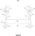
- FIG. 1A , 1B , 2A and 2B a hitch for connecting an implement to a vehicle is illustrated.
- the hitch comprises a first frame 100 for attachment to the vehicle and a second frame 200 for attachment to the implement.
- the first frame 100 is represented in a perspective view in Figure 1A and in a front view in Figure 1B .
- the first frame 100 comprises a pair of substantially L-shaped parallel elongated members 110 fixedly connected together.
- Each of the elongated members 110 comprises a first extremity 111 for attaching to the vehicle (not represented in Figures 1A and 1B for simplification purposes).
- Each of the elongated members 110 also comprises a second extremity 112 defining an internally substantially cylindrical wall 120.
- Each wall 120 projects internally from and downwardly between the pair of elongated members 110.
- each wall 120 may also project externally and upwardly from the pair of elongated members 110.
- the walls 120 may be integral to the elongated members 110.
- the walls 120 are secured to the elongated members 110, for instance by means of welding.
- the walls 120 may be a distinct part extending through an opening in the elongated members 110, and secured to the elongated members 110 by means of welding.
- each of the elongated members 110 further comprises a third extremity 113 projecting vertically from the second extremity 112, and defining an upper male connector 130.
- each upper male connector 130 consists of a transverse pin projecting externally from the pair of elongated members 110.
- the transverse pins 130 may be integral to the elongated members 110.
- the transverse pins 130 are secured to the elongated members 110, for instance by means of welding.
- the transverse pins 130 extend through an opening in the elongated members 110, and also project internally between the pair of elongated members 110.
- the position, orientation, size and particular design of the upper male connectors 130 may vary substantially, and are only limited by the position, orientation, size and particular design of a corresponding pair of female connectors which will be described later in the description.
- the pair of elongated members 110 are fixedly connected together by means of at least two transverse members 140 respectively extending between the pair of elongated members 110. Each extremity of the transverse members 140 is respectively connected to one of the pair of elongated members 110.
- the transverse members 140 may be integral to the elongated members 110. Alternatively, the transverse members 140 are secured to the elongated members 110, for instance by means of welding.
- Figures 1A and 1B represent two transverse members 140 of substantially cylindrical form, which may be hollow or full. However, the position, orientation, size and particular design of the transverse members 140 may vary substantially.
- a section 114 of the pair of elongated members 110 extending from the second extremity 112 to the third extremity 113 is oriented inwardly with respect to the pair of elongated members 110.
- the inwardly orientation of the third extremity 113 with respect to the second extremity 112 defines lateral clearance at the third extremity 113 with respect to the second extremity 112 for when the first frame 100 is inserted in the second frame 200.
- the first extremity 111 of the pair of elongated members 110 defines one of the following: a male connector adapted for attachment to a corresponding female connector of the vehicle or a female connector adapted for attachment to a corresponding male connector of the vehicle.
- the first extremity 111 defines a female connector 150, which consists of an internally substantially cylindrical wall adapted for receiving a corresponding male connector of the vehicle (not represented in Figures 1A and 1B for simplification purposes).
- one of the pair of elongated members 110 (the left one on Figure 1 A) further defines an additional female connector 160, which also consists of an internally substantially cylindrical wall adapted for receiving a corresponding male connector of the vehicle (not represented in Figures 1A and 1B for simplification purposes).
- the various components of the first frame 100 may be made of the same material or different materials.
- Example of such materials include one of the following: a metal, an alloy comprising one or more metals, etc.
- the hitch also comprises a second frame 200 for attachment to the implement.
- the second frame 200 is represented in a perspective view in Figure 2A and in a front view in Figure 2B .
- the second frame 200 comprises a pair of complementary linkage members 210 fixedly connected together.
- Each of the linkage members 210 comprises a first extremity 211 defining an upper female connector 230 for receiving one of the upper male connectors 130 of the first frame 100.
- Each upper female connector 230 consists of a downwardly-opening pin-receiving hook 230.
- the hooks 230 may be integral to the linkage members 210. Alternatively, the hooks 230 are secured to the linkage members 210, for instance by means of welding.
- the hooks 230 are adapted for receiving the transverse pins 130.
- the position, orientation, size and particular design of the upper female connectors 230 may vary substantially, and are only limited by the position, orientation, size and particular design of a corresponding pair of male connectors 130.
- Each of the linkage members 210 also comprises a second extremity 212 defining an internally substantially cylindrical wall 220 projecting externally from and upwardly away from the pair of complementary linkage members 210.
- the walls 220 may be integral to the linkage members 210.
- the walls 220 are secured to the linkage members 210, for instance by means of welding.
- the walls 220 are a distinct part extending through an opening in the linkage members 210, and secured to the linkage members 210 by means of welding.
- the second frame 200 also comprises an attachment for attaching the second frame 200 to the implement (not represented in Figures 2A and 2B for simplification purposes).
- the attachment to the implement may be designed via various mechanisms known in the art.
- the attachment comprises a pair of attachment members 250.
- Each attachment member 250 is secured to one of the two linkage members 210, for instance by means of welding, of by any other means known in the art.
- Each attachment member 250 also defines attachment means known in the art for attachment to the implement.
- each attachment member 250 may define one or more female connectors (as illustrated in Figure 2A ) adapted for attachment to one or more corresponding male connectors of the implement.
- each attachment member 250 defines one or more male connectors adapted for attachment to one or more corresponding female connectors of the implement.
- the position, orientation, size and particular design of the female connectors (or male connectors) of the attachment members 250 may vary substantially, and are only limited by the position, orientation, size and particular design of the corresponding male connectors (or female connectors) of the implement.
- the position, orientation, size and particular design of the attachment members 250 may vary substantially, and are only limited by the particular designs of the second frame 200 and implement.
- the pair of linkage members 210 are fixedly connected together by means of at least two transverse members 240 respectively extending between the pair of linkage members 210.
- Each extremity of the transverse members 240 is respectively connected to one of the pair of linkage members 210.
- the transverse members 240 may be integral to the linkage members 210.
- the transverse members 240 are secured to the linkage members 110, for instance by means of welding.
- Figures 2A and 2B represent two transverse members 240 of substantially cylindrical form, which may be hollow or full. However, the position, orientation, size and particular design of the transverse members 240 may vary substantially.
- the pair of linkage members 210 are oriented inwardly with respect to one another.
- the various components of the second frame 200 may be made of the same material or different materials.
- Example of such materials include one of the following: a metal, an alloy comprising one or more metals, etc.
- the hitch also comprises a pair of locking mechanisms 300 represented in Figures 2A and 2B .
- Each locking mechanism 300 is configured for engaging one of the walls 220 of the second frame 200 and a corresponding wall 120 of the first frame 100 when the upper female connectors 230 of the second frame 200 receive the upper male connectors 130 of the first frame 100.
- Figure 3 represents the first frame 100 and the second frame 200 before reception of the upper male connectors 130 of the first frame 100 by the upper female connectors 230 of the second frame 200.
- Each locking mechanism 300 has not engaged yet one of the walls 220 of the second frame 200 and a corresponding wall 120 of the first frame 100.
- Figure 4 represents the first frame 100 and the second frame 200 after reception of the upper male connectors 130 of the first frame 100 by the upper female connectors 230 of the second frame 200.
- Each locking mechanism 300 has engaged one of the walls 220 of the second frame 200 and a corresponding wall 120 of the first frame 100.
- the pair of locking mechanisms 300 is secured to the second frame 200, by any means known in the art.
- the pair of locking mechanisms 300 may be secured to the first frame 100 (this embodiment is not illustrated in the Figures).
- the pair of locking mechanisms 300 may consist in a pair of spring load pistons, as shown on the Figures. However, the pair of locking mechanisms 300 could consist of any type of mechanical locking mechanism known in the art, with or without springs.
- each locking mechanism 300 can engage one of the walls 220 of the second frame 200 and a corresponding wall 120 of the first frame 100 only when each of the walls 220 of the second frame 200 are aligned with their respective corresponding walls 120 of the first frame 100.
- This alignment occurs when the upper female connectors 230 of the second frame 200 receive the upper male connectors 130 of the first frame 100, and simultaneously the first frame 100 is positioned at a particular angle with respect to the second frame 200, the particular angle allowing each of the walls 220 of the second frame 200 to be aligned with their respective corresponding walls 120 of the first frame 100.
- the reception of the upper male connectors 130 of the first frame 100 by the upper female connectors 230 of the second frame 200 provides a rotational degree of liberty of the first frame 100 with respect to the second frame 200.
- This rotational degree of liberty allows positioning the first frame 100 at the particular angle with respect to the second frame 200.
- the particular angle corresponds to having each of the walls 220 of the second frame 200 to be aligned with their respective corresponding walls 120 of the first frame 100.
- Each linkage member 210 comprises a stop 260 projecting internally between the pair of linkage members 210.
- the stops 260 are configured for allowing abutment of the first frame 100 against the stops 260 when the upper female connectors 230 of the second frame 200 receive the upper male connectors 130 of the first frame 100.
- the stops 260 may be integral to the linkage members 210. Alternatively, the stops 260 are secured to the linkage members 210, for instance by means of welding.
- the stops 260 are further configured so that when the abutment occurs, each of the walls 220 of the second frame 200 are aligned with their respective corresponding walls 120 of the first frame 100, therefore allowing engagement of each locking mechanism 300 with one of the walls 220 of the second frame 200 and the corresponding wall 120 of the first frame 100.
- the position, orientation, size and particular design of the stops 260 may vary substantially, and are only limited by the aforementioned function of the stops 260, which consists in providing abutment of the first frame 100 for allowing engagement of the locking
- Figure 5 represents the first frame 100 and the second frame 200 of Figure 3 , before reception of the upper male connectors 130 of the first frame 100 by the upper female connectors 230 of the second frame 200.
- Figure 5 further represents the first frame 100 being attached to a vehicle 400 and the second frame 200 being attached to an implement 500.
- Figure 6 represents the first frame 100 and the second frame 200 of Figure 4 after reception of the upper male connectors 130 of the first frame 100 by the upper female connectors 230 of the second frame 200.
- Each locking mechanism 300 has engaged one of the walls 220 of the second frame 200 and the corresponding wall 120 of the first frame 100.
- Figure 6 further represents the first frame 100 being attached to the vehicle 400 and the second frame 200 being attached to the implement 500.
- the vehicle 400 and the implement 500 are only partially represented in Figures 5 and 6 for simplification purposes.
- the attachment of the first frame 100 to the vehicle 400 and the attachment of the second frame 200 to the implement 500 have already been detailed previously in relation to Figures 1A , 1B , 2A and 2B .
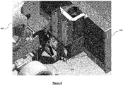
- Figure 6 illustrates the implement 500 connected to the vehicle 400 by means of the present hitch.
- the connection occurs when the first frame 100 is attached to the vehicle 400, the second frame 200 is attached to the implement 500, and when the upper male connectors 130 of the first frame 100 are received and engaged into the upper female connectors 230 of the second frame 200, and engagement of each locking mechanism 300 with one of the walls 220 of the second frame 200 and the corresponding wall 120 of the first frame 100.
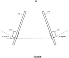
- FIG. 7A is a simplified representation of the first frame 100 corresponding to Figure 1B , and illustrating the walls 120 of the first frame 100 projecting internally from and downwardly between the pair of elongated members 110 at an angle of substantially 15 degrees with respect to a horizontal reference.
- Figure 7B is a simplified representation of the second frame 200 corresponding to Figure 2B , and illustrating the walls 220 of the second frame 200 projecting externally from and upwardly away from the pair of linkage members 210 at an angle of substantially 15 degrees with respect to a horizontal reference.
- the angle of substantially 15 degrees has been experimentally determined to be an angle particularly adapted for facilitating the connection of the implement 500 to the vehicle 400.
- Figures 7C is a simplified representation of the first frame 100 illustrated in Figure 7A and the second frame 200 illustrated in Figure 7B when respectively positioned in the configuration allowing connection of the implement 500 to the vehicle 400 via engagement of the pair of locking mechanisms 300 (represented by arrows for simplification purposes).
- the second extremity 112 of each elongated member 110 of the first frame 100 is substantially horizontal to ground level when the first frame 100 is installed on a vehicle as shown on Figure 5 .
- the substantially horizontal orientation of the second extremity 112 of the first frame 100 further facilitates the connection of the implement 500 to the vehicle 400 when respectively attached to the second frame 200 and first frame 100 by providing a lateral clearance on each side of the first frame 100 with respect to the second frame 200 when the first frame 100 is lowered by a piston for positioning in the second frame 200.
- the lateral clearance facilitates the positioning of the first frame 100 with respect to the second frame 200.
- an operator of the tractor lowers the first frame 100 by use of the piston (shown on Figure 6 ), and approaches the first frame 100 to the second frame 200.
- the inclination of the third extremity 114 of the L-shaped members 110 provides the lateral clearance between the lowered first frame 100 with respect to the second frame 200.
- the operator of the tractor raises the first frame 100 by use of the piston, into the second frame 200, thereby gradually reducing the lateral clearance between the first frame 100 and the second frame 200, and allowing smooth insertion of the upper male connectors 130 of the first frame 100 into the upper female connectors 230 of the second frame 200.
- the second frame 200 When the upper male connectors 130 of the first frame are securely inserted into the upper female connectors 230 of the second frame, the second frame 200 is lifted and by gravity rotates the second frame 200 until the second extremities of the L-shaped parallel elongated members 110 are abutted against the stops 260 of the second frame. The operator may then actuate the pair of locking mechanisms 300 so as to lock the implement to the tractor.
Landscapes
- Life Sciences & Earth Sciences (AREA)
- Zoology (AREA)
- Engineering & Computer Science (AREA)
- Mechanical Engineering (AREA)
- Soil Sciences (AREA)
- Environmental Sciences (AREA)
- Agricultural Machines (AREA)
Applications Claiming Priority (1)
| Application Number | Priority Date | Filing Date | Title |
|---|---|---|---|
| US201662288578P | 2016-01-29 | 2016-01-29 |
Publications (2)
| Publication Number | Publication Date |
|---|---|
| EP3202242A1 true EP3202242A1 (fr) | 2017-08-09 |
| EP3202242B1 EP3202242B1 (fr) | 2023-06-14 |
Family
ID=57914780
Family Applications (1)
| Application Number | Title | Priority Date | Filing Date |
|---|---|---|---|
| EP17153158.5A Active EP3202242B1 (fr) | 2016-01-29 | 2017-01-25 | Attelage permettant de relier un outil à un véhicule |
Country Status (4)
| Country | Link |
|---|---|
| US (1) | US10736253B2 (fr) |
| EP (1) | EP3202242B1 (fr) |
| JP (1) | JP6759117B2 (fr) |
| CA (1) | CA2955886C (fr) |
Citations (5)
| Publication number | Priority date | Publication date | Assignee | Title |
|---|---|---|---|---|
| US3048228A (en) * | 1960-05-18 | 1962-08-07 | Deere & Co | Hitch device |
| US3173496A (en) * | 1961-05-03 | 1965-03-16 | Massey Ferguson Ltd | Tractor hitch arrangement |
| GB1021219A (en) * | 1964-09-05 | 1966-03-02 | Inst Landmasch & Traktorenbau | Improvements in or relating to devices for coupling implements |
| NL8103318A (nl) * | 1981-07-11 | 1983-02-01 | Martinus Elisabeth Aloysius Be | Inrichting voor het aankoppelen van een landbouwwerktuig. |
| US5029650A (en) * | 1989-10-20 | 1991-07-09 | Sukup Manufacturing Company | Adjustable quick attaching hitch coupler |
Family Cites Families (8)
| Publication number | Priority date | Publication date | Assignee | Title |
|---|---|---|---|---|
| US3351357A (en) * | 1965-10-22 | 1967-11-07 | Ralph D Van Eaton | Agricultural implement coupler |
| US3987562A (en) * | 1975-06-02 | 1976-10-26 | American Equipment Corporation | Quick connect snow plow implement |
| US5125174A (en) * | 1991-04-15 | 1992-06-30 | Douglas Dynamics, Inc. | Removable snowflow with a pivotable lift stand |
| US5568694A (en) * | 1993-12-15 | 1996-10-29 | M. J. Electric, Inc. | Behind the bumper, quick attachment system and mechanism for truck mounted snow plows |
| US6178669B1 (en) * | 1999-02-03 | 2001-01-30 | Blizzard Corporation | Plow hitch assembly for vehicles |
| US6354024B1 (en) * | 1999-11-29 | 2002-03-12 | The Louis Berkman Company | Snowplow mount |
| US6526677B1 (en) * | 2000-10-06 | 2003-03-04 | Douglas Dynamics, L.L.C. | Snowplow mounting assembly |
| US7841110B2 (en) * | 2008-06-17 | 2010-11-30 | Sno-Way International, Inc. | Plow quick connect/disconnect hitch mechanism |
-
2017
- 2017-01-24 CA CA2955886A patent/CA2955886C/fr active Active
- 2017-01-25 EP EP17153158.5A patent/EP3202242B1/fr active Active
- 2017-01-25 US US15/414,687 patent/US10736253B2/en active Active
- 2017-01-30 JP JP2017014032A patent/JP6759117B2/ja active Active
Patent Citations (5)
| Publication number | Priority date | Publication date | Assignee | Title |
|---|---|---|---|---|
| US3048228A (en) * | 1960-05-18 | 1962-08-07 | Deere & Co | Hitch device |
| US3173496A (en) * | 1961-05-03 | 1965-03-16 | Massey Ferguson Ltd | Tractor hitch arrangement |
| GB1021219A (en) * | 1964-09-05 | 1966-03-02 | Inst Landmasch & Traktorenbau | Improvements in or relating to devices for coupling implements |
| NL8103318A (nl) * | 1981-07-11 | 1983-02-01 | Martinus Elisabeth Aloysius Be | Inrichting voor het aankoppelen van een landbouwwerktuig. |
| US5029650A (en) * | 1989-10-20 | 1991-07-09 | Sukup Manufacturing Company | Adjustable quick attaching hitch coupler |
Also Published As
| Publication number | Publication date |
|---|---|
| US10736253B2 (en) | 2020-08-11 |
| JP6759117B2 (ja) | 2020-09-23 |
| US20170215326A1 (en) | 2017-08-03 |
| CA2955886C (fr) | 2018-11-20 |
| JP2017137049A (ja) | 2017-08-10 |
| CA2955886A1 (fr) | 2017-07-29 |
| EP3202242B1 (fr) | 2023-06-14 |
Similar Documents
| Publication | Publication Date | Title |
|---|---|---|
| US9184532B2 (en) | Socket with a cover lock | |
| US10195913B2 (en) | Two-point hitch mount systems | |
| US6536794B2 (en) | Tow hitch assembly for all-terrain vehicles | |
| US20160113188A1 (en) | Tractor-implement coupling mechanism | |
| US9487928B1 (en) | Receiver plate-coupler plate assembly | |
| US9193231B2 (en) | Drawbar hitch mount assemblies | |
| EP3553323B1 (fr) | Système de soupape de dérivation à actionnement automatique | |
| JP2021502117A (ja) | ドッキング受容部及びドッキングインサートを有するドッキング装置並びに車両を連結するための方法 | |
| US9168800B2 (en) | Multi-configuration, multi-pin drawbar retention assembly | |
| US10736253B2 (en) | Hitch for connecting an implement to a vehicle | |
| EP2130420A1 (fr) | Crochets à outils pour tracteur | |
| EP2870842B1 (fr) | Attaches de crochet à outils pour tracteur | |
| US7048294B2 (en) | Locking bolt for a towing device | |
| US7565758B2 (en) | Quick attach coupling device | |
| EP2362024A2 (fr) | Couplage rapide pour outil de creusement ou de chargement | |
| EP1016340A2 (fr) | Dispositif automatique d'accouplement multifonctionnel pour outils agricoles ou équivalents | |
| US9121162B1 (en) | Motor coupler with multiple pick up locations | |
| US20160362145A1 (en) | Mounting arrangement for coupling work tool attachment with machine | |
| CA2696254C (fr) | Tige d'attelage et appareil d'attelage | |
| US2544181A (en) | Trailer hitch for tractors | |
| WO2015089627A1 (fr) | Taquet annulaire pour attelage | |
| US12564118B2 (en) | Draft link for a three-point hitch | |
| JP6212410B2 (ja) | クイックカプラ及び産業用車両 | |
| CN211995046U (zh) | 拖挂装置 | |
| US9555842B1 (en) | Adapter bracket assembly configured to adapt a utility vehicle for use with a different utility component |
Legal Events
| Date | Code | Title | Description |
|---|---|---|---|
| PUAI | Public reference made under article 153(3) epc to a published international application that has entered the european phase |
Free format text: ORIGINAL CODE: 0009012 |
|
| STAA | Information on the status of an ep patent application or granted ep patent |
Free format text: STATUS: THE APPLICATION HAS BEEN PUBLISHED |
|
| AK | Designated contracting states |
Kind code of ref document: A1 Designated state(s): AL AT BE BG CH CY CZ DE DK EE ES FI FR GB GR HR HU IE IS IT LI LT LU LV MC MK MT NL NO PL PT RO RS SE SI SK SM TR |
|
| AX | Request for extension of the european patent |
Extension state: BA ME |
|
| RAP1 | Party data changed (applicant data changed or rights of an application transferred) |
Owner name: RAD TECHNOLOGIES INC. |
|
| STAA | Information on the status of an ep patent application or granted ep patent |
Free format text: STATUS: REQUEST FOR EXAMINATION WAS MADE |
|
| 17P | Request for examination filed |
Effective date: 20180208 |
|
| RBV | Designated contracting states (corrected) |
Designated state(s): AL AT BE BG CH CY CZ DE DK EE ES FI FR GB GR HR HU IE IS IT LI LT LU LV MC MK MT NL NO PL PT RO RS SE SI SK SM TR |
|
| STAA | Information on the status of an ep patent application or granted ep patent |
Free format text: STATUS: EXAMINATION IS IN PROGRESS |
|
| 17Q | First examination report despatched |
Effective date: 20210223 |
|
| GRAP | Despatch of communication of intention to grant a patent |
Free format text: ORIGINAL CODE: EPIDOSNIGR1 |
|
| STAA | Information on the status of an ep patent application or granted ep patent |
Free format text: STATUS: GRANT OF PATENT IS INTENDED |
|
| INTG | Intention to grant announced |
Effective date: 20230102 |
|
| GRAS | Grant fee paid |
Free format text: ORIGINAL CODE: EPIDOSNIGR3 |
|
| GRAA | (expected) grant |
Free format text: ORIGINAL CODE: 0009210 |
|
| STAA | Information on the status of an ep patent application or granted ep patent |
Free format text: STATUS: THE PATENT HAS BEEN GRANTED |
|
| AK | Designated contracting states |
Kind code of ref document: B1 Designated state(s): AL AT BE BG CH CY CZ DE DK EE ES FI FR GB GR HR HU IE IS IT LI LT LU LV MC MK MT NL NO PL PT RO RS SE SI SK SM TR |
|
| REG | Reference to a national code |
Ref country code: CH Ref legal event code: EP |
|
| REG | Reference to a national code |
Ref country code: DE Ref legal event code: R096 Ref document number: 602017070135 Country of ref document: DE |
|
| REG | Reference to a national code |
Ref country code: AT Ref legal event code: REF Ref document number: 1578513 Country of ref document: AT Kind code of ref document: T Effective date: 20230715 |
|
| REG | Reference to a national code |
Ref country code: LT Ref legal event code: MG9D |
|
| REG | Reference to a national code |
Ref country code: NL Ref legal event code: MP Effective date: 20230614 |
|
| PG25 | Lapsed in a contracting state [announced via postgrant information from national office to epo] |
Ref country code: SE Free format text: LAPSE BECAUSE OF FAILURE TO SUBMIT A TRANSLATION OF THE DESCRIPTION OR TO PAY THE FEE WITHIN THE PRESCRIBED TIME-LIMIT Effective date: 20230614 Ref country code: NO Free format text: LAPSE BECAUSE OF FAILURE TO SUBMIT A TRANSLATION OF THE DESCRIPTION OR TO PAY THE FEE WITHIN THE PRESCRIBED TIME-LIMIT Effective date: 20230914 Ref country code: ES Free format text: LAPSE BECAUSE OF FAILURE TO SUBMIT A TRANSLATION OF THE DESCRIPTION OR TO PAY THE FEE WITHIN THE PRESCRIBED TIME-LIMIT Effective date: 20230614 |
|
| REG | Reference to a national code |
Ref country code: AT Ref legal event code: MK05 Ref document number: 1578513 Country of ref document: AT Kind code of ref document: T Effective date: 20230614 |
|
| PG25 | Lapsed in a contracting state [announced via postgrant information from national office to epo] |
Ref country code: RS Free format text: LAPSE BECAUSE OF FAILURE TO SUBMIT A TRANSLATION OF THE DESCRIPTION OR TO PAY THE FEE WITHIN THE PRESCRIBED TIME-LIMIT Effective date: 20230614 Ref country code: NL Free format text: LAPSE BECAUSE OF FAILURE TO SUBMIT A TRANSLATION OF THE DESCRIPTION OR TO PAY THE FEE WITHIN THE PRESCRIBED TIME-LIMIT Effective date: 20230614 Ref country code: LV Free format text: LAPSE BECAUSE OF FAILURE TO SUBMIT A TRANSLATION OF THE DESCRIPTION OR TO PAY THE FEE WITHIN THE PRESCRIBED TIME-LIMIT Effective date: 20230614 Ref country code: LT Free format text: LAPSE BECAUSE OF FAILURE TO SUBMIT A TRANSLATION OF THE DESCRIPTION OR TO PAY THE FEE WITHIN THE PRESCRIBED TIME-LIMIT Effective date: 20230614 Ref country code: HR Free format text: LAPSE BECAUSE OF FAILURE TO SUBMIT A TRANSLATION OF THE DESCRIPTION OR TO PAY THE FEE WITHIN THE PRESCRIBED TIME-LIMIT Effective date: 20230614 Ref country code: GR Free format text: LAPSE BECAUSE OF FAILURE TO SUBMIT A TRANSLATION OF THE DESCRIPTION OR TO PAY THE FEE WITHIN THE PRESCRIBED TIME-LIMIT Effective date: 20230915 |
|
| PG25 | Lapsed in a contracting state [announced via postgrant information from national office to epo] |
Ref country code: FI Free format text: LAPSE BECAUSE OF FAILURE TO SUBMIT A TRANSLATION OF THE DESCRIPTION OR TO PAY THE FEE WITHIN THE PRESCRIBED TIME-LIMIT Effective date: 20230614 |
|
| PG25 | Lapsed in a contracting state [announced via postgrant information from national office to epo] |
Ref country code: SK Free format text: LAPSE BECAUSE OF FAILURE TO SUBMIT A TRANSLATION OF THE DESCRIPTION OR TO PAY THE FEE WITHIN THE PRESCRIBED TIME-LIMIT Effective date: 20230614 |
|
| PG25 | Lapsed in a contracting state [announced via postgrant information from national office to epo] |
Ref country code: IS Free format text: LAPSE BECAUSE OF FAILURE TO SUBMIT A TRANSLATION OF THE DESCRIPTION OR TO PAY THE FEE WITHIN THE PRESCRIBED TIME-LIMIT Effective date: 20231014 |
|
| PG25 | Lapsed in a contracting state [announced via postgrant information from national office to epo] |
Ref country code: SM Free format text: LAPSE BECAUSE OF FAILURE TO SUBMIT A TRANSLATION OF THE DESCRIPTION OR TO PAY THE FEE WITHIN THE PRESCRIBED TIME-LIMIT Effective date: 20230614 Ref country code: SK Free format text: LAPSE BECAUSE OF FAILURE TO SUBMIT A TRANSLATION OF THE DESCRIPTION OR TO PAY THE FEE WITHIN THE PRESCRIBED TIME-LIMIT Effective date: 20230614 Ref country code: RO Free format text: LAPSE BECAUSE OF FAILURE TO SUBMIT A TRANSLATION OF THE DESCRIPTION OR TO PAY THE FEE WITHIN THE PRESCRIBED TIME-LIMIT Effective date: 20230614 Ref country code: PT Free format text: LAPSE BECAUSE OF FAILURE TO SUBMIT A TRANSLATION OF THE DESCRIPTION OR TO PAY THE FEE WITHIN THE PRESCRIBED TIME-LIMIT Effective date: 20231016 Ref country code: IS Free format text: LAPSE BECAUSE OF FAILURE TO SUBMIT A TRANSLATION OF THE DESCRIPTION OR TO PAY THE FEE WITHIN THE PRESCRIBED TIME-LIMIT Effective date: 20231014 Ref country code: EE Free format text: LAPSE BECAUSE OF FAILURE TO SUBMIT A TRANSLATION OF THE DESCRIPTION OR TO PAY THE FEE WITHIN THE PRESCRIBED TIME-LIMIT Effective date: 20230614 Ref country code: CZ Free format text: LAPSE BECAUSE OF FAILURE TO SUBMIT A TRANSLATION OF THE DESCRIPTION OR TO PAY THE FEE WITHIN THE PRESCRIBED TIME-LIMIT Effective date: 20230614 Ref country code: AT Free format text: LAPSE BECAUSE OF FAILURE TO SUBMIT A TRANSLATION OF THE DESCRIPTION OR TO PAY THE FEE WITHIN THE PRESCRIBED TIME-LIMIT Effective date: 20230614 |
|
| PG25 | Lapsed in a contracting state [announced via postgrant information from national office to epo] |
Ref country code: PL Free format text: LAPSE BECAUSE OF FAILURE TO SUBMIT A TRANSLATION OF THE DESCRIPTION OR TO PAY THE FEE WITHIN THE PRESCRIBED TIME-LIMIT Effective date: 20230614 |
|
| REG | Reference to a national code |
Ref country code: DE Ref legal event code: R097 Ref document number: 602017070135 Country of ref document: DE |
|
| PLBE | No opposition filed within time limit |
Free format text: ORIGINAL CODE: 0009261 |
|
| STAA | Information on the status of an ep patent application or granted ep patent |
Free format text: STATUS: NO OPPOSITION FILED WITHIN TIME LIMIT |
|
| PG25 | Lapsed in a contracting state [announced via postgrant information from national office to epo] |
Ref country code: DK Free format text: LAPSE BECAUSE OF FAILURE TO SUBMIT A TRANSLATION OF THE DESCRIPTION OR TO PAY THE FEE WITHIN THE PRESCRIBED TIME-LIMIT Effective date: 20230614 |
|
| PG25 | Lapsed in a contracting state [announced via postgrant information from national office to epo] |
Ref country code: SI Free format text: LAPSE BECAUSE OF FAILURE TO SUBMIT A TRANSLATION OF THE DESCRIPTION OR TO PAY THE FEE WITHIN THE PRESCRIBED TIME-LIMIT Effective date: 20230614 |
|
| 26N | No opposition filed |
Effective date: 20240315 |
|
| PG25 | Lapsed in a contracting state [announced via postgrant information from national office to epo] |
Ref country code: SI Free format text: LAPSE BECAUSE OF FAILURE TO SUBMIT A TRANSLATION OF THE DESCRIPTION OR TO PAY THE FEE WITHIN THE PRESCRIBED TIME-LIMIT Effective date: 20230614 Ref country code: IT Free format text: LAPSE BECAUSE OF FAILURE TO SUBMIT A TRANSLATION OF THE DESCRIPTION OR TO PAY THE FEE WITHIN THE PRESCRIBED TIME-LIMIT Effective date: 20230614 |
|
| PG25 | Lapsed in a contracting state [announced via postgrant information from national office to epo] |
Ref country code: MC Free format text: LAPSE BECAUSE OF FAILURE TO SUBMIT A TRANSLATION OF THE DESCRIPTION OR TO PAY THE FEE WITHIN THE PRESCRIBED TIME-LIMIT Effective date: 20230614 |
|
| PG25 | Lapsed in a contracting state [announced via postgrant information from national office to epo] |
Ref country code: MC Free format text: LAPSE BECAUSE OF FAILURE TO SUBMIT A TRANSLATION OF THE DESCRIPTION OR TO PAY THE FEE WITHIN THE PRESCRIBED TIME-LIMIT Effective date: 20230614 |
|
| REG | Reference to a national code |
Ref country code: CH Ref legal event code: PL |
|
| PG25 | Lapsed in a contracting state [announced via postgrant information from national office to epo] |
Ref country code: LU Free format text: LAPSE BECAUSE OF NON-PAYMENT OF DUE FEES Effective date: 20240125 |
|
| PG25 | Lapsed in a contracting state [announced via postgrant information from national office to epo] |
Ref country code: LU Free format text: LAPSE BECAUSE OF NON-PAYMENT OF DUE FEES Effective date: 20240125 |
|
| PG25 | Lapsed in a contracting state [announced via postgrant information from national office to epo] |
Ref country code: BE Free format text: LAPSE BECAUSE OF NON-PAYMENT OF DUE FEES Effective date: 20240131 |
|
| PG25 | Lapsed in a contracting state [announced via postgrant information from national office to epo] |
Ref country code: CH Free format text: LAPSE BECAUSE OF NON-PAYMENT OF DUE FEES Effective date: 20240131 |
|
| PG25 | Lapsed in a contracting state [announced via postgrant information from national office to epo] |
Ref country code: CH Free format text: LAPSE BECAUSE OF NON-PAYMENT OF DUE FEES Effective date: 20240131 Ref country code: BE Free format text: LAPSE BECAUSE OF NON-PAYMENT OF DUE FEES Effective date: 20240131 |
|
| REG | Reference to a national code |
Ref country code: BE Ref legal event code: MM Effective date: 20240131 |
|
| PG25 | Lapsed in a contracting state [announced via postgrant information from national office to epo] |
Ref country code: BG Free format text: LAPSE BECAUSE OF FAILURE TO SUBMIT A TRANSLATION OF THE DESCRIPTION OR TO PAY THE FEE WITHIN THE PRESCRIBED TIME-LIMIT Effective date: 20230614 |
|
| PG25 | Lapsed in a contracting state [announced via postgrant information from national office to epo] |
Ref country code: BG Free format text: LAPSE BECAUSE OF FAILURE TO SUBMIT A TRANSLATION OF THE DESCRIPTION OR TO PAY THE FEE WITHIN THE PRESCRIBED TIME-LIMIT Effective date: 20230614 |
|
| PG25 | Lapsed in a contracting state [announced via postgrant information from national office to epo] |
Ref country code: IE Free format text: LAPSE BECAUSE OF NON-PAYMENT OF DUE FEES Effective date: 20240125 |
|
| PG25 | Lapsed in a contracting state [announced via postgrant information from national office to epo] |
Ref country code: IE Free format text: LAPSE BECAUSE OF NON-PAYMENT OF DUE FEES Effective date: 20240125 |
|
| PG25 | Lapsed in a contracting state [announced via postgrant information from national office to epo] |
Ref country code: CY Free format text: LAPSE BECAUSE OF FAILURE TO SUBMIT A TRANSLATION OF THE DESCRIPTION OR TO PAY THE FEE WITHIN THE PRESCRIBED TIME-LIMIT; INVALID AB INITIO Effective date: 20170125 |
|
| PG25 | Lapsed in a contracting state [announced via postgrant information from national office to epo] |
Ref country code: HU Free format text: LAPSE BECAUSE OF FAILURE TO SUBMIT A TRANSLATION OF THE DESCRIPTION OR TO PAY THE FEE WITHIN THE PRESCRIBED TIME-LIMIT; INVALID AB INITIO Effective date: 20170125 |
|
| PG25 | Lapsed in a contracting state [announced via postgrant information from national office to epo] |
Ref country code: TR Free format text: LAPSE BECAUSE OF FAILURE TO SUBMIT A TRANSLATION OF THE DESCRIPTION OR TO PAY THE FEE WITHIN THE PRESCRIBED TIME-LIMIT Effective date: 20230614 |
|
| PGFP | Annual fee paid to national office [announced via postgrant information from national office to epo] |
Ref country code: GB Payment date: 20260126 Year of fee payment: 10 |
|
| PGFP | Annual fee paid to national office [announced via postgrant information from national office to epo] |
Ref country code: DE Payment date: 20260127 Year of fee payment: 10 |
|
| PGFP | Annual fee paid to national office [announced via postgrant information from national office to epo] |
Ref country code: FR Payment date: 20260126 Year of fee payment: 10 |