EP3202286B1 - Warenpräsentationseinheit - Google Patents
Warenpräsentationseinheit Download PDFInfo
- Publication number
- EP3202286B1 EP3202286B1 EP16186125.7A EP16186125A EP3202286B1 EP 3202286 B1 EP3202286 B1 EP 3202286B1 EP 16186125 A EP16186125 A EP 16186125A EP 3202286 B1 EP3202286 B1 EP 3202286B1
- Authority
- EP
- European Patent Office
- Prior art keywords
- pusher
- display unit
- barrier
- product display
- product
- Prior art date
- Legal status (The legal status is an assumption and is not a legal conclusion. Google has not performed a legal analysis and makes no representation as to the accuracy of the status listed.)
- Not-in-force
Links
- 230000004888 barrier function Effects 0.000 claims description 82
- 230000005484 gravity Effects 0.000 claims description 22
- 239000000463 material Substances 0.000 claims description 6
- 230000006835 compression Effects 0.000 claims 1
- 238000007906 compression Methods 0.000 claims 1
- 238000004806 packaging method and process Methods 0.000 description 10
- 238000011161 development Methods 0.000 description 4
- 230000018109 developmental process Effects 0.000 description 4
- 239000004033 plastic Substances 0.000 description 4
- 229920003023 plastic Polymers 0.000 description 4
- 229910052782 aluminium Inorganic materials 0.000 description 2
- XAGFODPZIPBFFR-UHFFFAOYSA-N aluminium Chemical compound [Al] XAGFODPZIPBFFR-UHFFFAOYSA-N 0.000 description 2
- 230000015572 biosynthetic process Effects 0.000 description 2
- 239000002131 composite material Substances 0.000 description 2
- 238000005755 formation reaction Methods 0.000 description 2
- 238000000034 method Methods 0.000 description 2
- 238000003825 pressing Methods 0.000 description 2
- XECAHXYUAAWDEL-UHFFFAOYSA-N acrylonitrile butadiene styrene Chemical compound C=CC=C.C=CC#N.C=CC1=CC=CC=C1 XECAHXYUAAWDEL-UHFFFAOYSA-N 0.000 description 1
- 229920000122 acrylonitrile butadiene styrene Polymers 0.000 description 1
- 239000004676 acrylonitrile butadiene styrene Substances 0.000 description 1
- 238000005266 casting Methods 0.000 description 1
- 238000009826 distribution Methods 0.000 description 1
- 238000000605 extraction Methods 0.000 description 1
- 238000001125 extrusion Methods 0.000 description 1
- 210000003746 feather Anatomy 0.000 description 1
- 238000001746 injection moulding Methods 0.000 description 1
- 238000009434 installation Methods 0.000 description 1
- 238000005304 joining Methods 0.000 description 1
- 229910052751 metal Inorganic materials 0.000 description 1
- 239000002184 metal Substances 0.000 description 1
- 238000003860 storage Methods 0.000 description 1
- 229920001169 thermoplastic Polymers 0.000 description 1
- 239000004416 thermosoftening plastic Substances 0.000 description 1
Images





Classifications
-
- A—HUMAN NECESSITIES
- A47—FURNITURE; DOMESTIC ARTICLES OR APPLIANCES; COFFEE MILLS; SPICE MILLS; SUCTION CLEANERS IN GENERAL
- A47F—SPECIAL FURNITURE, FITTINGS, OR ACCESSORIES FOR SHOPS, STOREHOUSES, BARS, RESTAURANTS OR THE LIKE; PAYING COUNTERS
- A47F1/00—Racks for dispensing merchandise; Containers for dispensing merchandise
- A47F1/04—Racks or containers with arrangements for dispensing articles, e.g. by means of gravity or springs
- A47F1/12—Racks or containers with arrangements for dispensing articles, e.g. by means of gravity or springs dispensing from the side of an approximately horizontal stack
- A47F1/125—Racks or containers with arrangements for dispensing articles, e.g. by means of gravity or springs dispensing from the side of an approximately horizontal stack with an article-pushing device
- A47F1/126—Racks or containers with arrangements for dispensing articles, e.g. by means of gravity or springs dispensing from the side of an approximately horizontal stack with an article-pushing device the pushing device being urged by spring means
-
- A—HUMAN NECESSITIES
- A47—FURNITURE; DOMESTIC ARTICLES OR APPLIANCES; COFFEE MILLS; SPICE MILLS; SUCTION CLEANERS IN GENERAL
- A47F—SPECIAL FURNITURE, FITTINGS, OR ACCESSORIES FOR SHOPS, STOREHOUSES, BARS, RESTAURANTS OR THE LIKE; PAYING COUNTERS
- A47F5/00—Show stands, hangers, or shelves characterised by their constructional features
- A47F5/0043—Show shelves
- A47F5/005—Partitions therefore
-
- A—HUMAN NECESSITIES
- A47—FURNITURE; DOMESTIC ARTICLES OR APPLIANCES; COFFEE MILLS; SPICE MILLS; SUCTION CLEANERS IN GENERAL
- A47F—SPECIAL FURNITURE, FITTINGS, OR ACCESSORIES FOR SHOPS, STOREHOUSES, BARS, RESTAURANTS OR THE LIKE; PAYING COUNTERS
- A47F5/00—Show stands, hangers, or shelves characterised by their constructional features
- A47F5/10—Adjustable or foldable or dismountable display stands
Definitions
- the present invention relates to a goods presentation unit according to claim 1
- the present disclosure relates to the field of retail product storage and presentation units. More particularly, the disclosure relates to retail merchandise presentation units in which the product packages or bundles are loaded from a front end of the presentation unit.
- Goods presentation units are known in particular as modular goods presentation units that can be mounted on a shelf individually, side by side or vertically separated from each other.
- the product packages or bundles may be driven by gravity to a front end of the merchandising unit, for example, a sloping floor and a plurality of rollers may be used, so that the drive is realized solely by gravity.
- a front end of the merchandising unit for example, a sloping floor and a plurality of rollers may be used, so that the drive is realized solely by gravity.
- the product packaging will pass through held a barrier. Once product packaging is removed, the remaining product packages are forced by gravity toward the barrier.
- merchandise display units use a pretensioned platen or pusher which contacts the rearmost product package and urges all packages arranged on the merchandise display unit in a row toward the front end of the merchandise display unit.
- the goods presentation units are loaded from the top.
- the product packages are simply placed on the bottom of the goods presentation unit.
- pusher-driven merchandise display units the pusher is moved backwards and product packaging is inserted into the space between the barrier and the pusher. Then the pusher is put into operation.
- the object of the present invention is to provide a product handling unit which is easier to handle, in which the product packages are efficiently forced to the front end of the goods presentation unit.
- the invention is based on the idea to provide a goods presentation unit in which a goods presentation base is modularly formed with a pusher track, which is formed by latching means with a pusher bar for latching with a pusher and / or has at least a gravity-operated barrier at a front end of the goods presentation base , which is designed to be rotatable about an axis extending substantially perpendicular to the plane of the Pusherbahn.
- a goods presentation base is modularly formed with a pusher track, which is formed by latching means with a pusher bar for latching with a pusher and / or has at least a gravity-operated barrier at a front end of the goods presentation base , which is designed to be rotatable about an axis extending substantially perpendicular to the plane of the Pusherbahn.
- the goods presentation unit has at least one pusher which can be mounted with the pusher bar and is guided along the pusher bar and can be moved up to the front end cap.
- This is preferably spring actuated, in particular by means of a helical spring, wherein the front end cap preferably has a retaining groove for a arranged at the end of the coil spring tongue, and wherein the at least one pusher preferably at its bottom inwardly directed sidebars, which has a channel for inserting the pusher bar define.
- a product presentation unit is disclosed with a pusher having an adjustable pusher surface.
- adjustable is meant in particular the size of the pusher surface and / or the shape of the pusher surface, in particular by unfolding or extending one, preferably designed as Rotierarm, movable on the pusher arranged component.
- the component is preferably latched or latched to the pusher housing.
- the latter has at least one product row separator which extends in particular in a direction parallel to the at least one pusher track and / or in a plane substantially perpendicular to the plane of the at least one pusher track.
- the at least one product row separator with the at least one pusher track and the front end cap is formed as a unit, in particular inseparable and / or from a single material.
- the goods presentation unit has a rear barrier at a longitudinal end of the at least one pusher track opposite the front end cap.
- the pusher track, the front end cap and the rear barrier are formed as a unit, preferably inseparable and / or from a single material.
- the front end cap has mounting features for fixing / securing the front end cap on a front strip extending in a direction transverse to the length of the at least one pusher track.
- the goods presentation unit has, in particular, means for urging the product packages along the goods presentation base in the direction of the front end cap.
- the means for urging in particular have a roller conveyor with a plurality of rollers.
- the roller conveyor is preferably inclined, in particular with a gradient, so that the force of gravity Product packaging in the direction of the gravity-actuated barrier is formed urgent.
- FIG. 1 shows a perspective view of an embodiment of a goods presentation unit with a goods presentation base 11 as described below.
- the goods presentation base 11 has in particular at least one pusher track 18, which extends in particular from a front end cap 16 to a rear barrier 14.
- a product row separator 12 may be attached to the merchandise presentation base 11 and oriented in a plane substantially perpendicular to the plane of the pen web 18.
- a second push track 18 is disposed on the opposite side of the product row separator 12.
- a gravity-operated front barrier 20 may be mounted on an axis that is substantially perpendicular to the plane of the pusher track 18 and / or parallel to the product row separator 12.
- the front barrier 20 may include one or two gravity-operated front barrier doors, discussed below with respect to FIG FIG. 5 be explained.
- FIG. 2 shows examples of a pusher bar 19, which can be clipped into the corresponding Pusherbahnen 18 to a corresponding pusher 22 (see FIG. 3 ) to be mounted on the merchandise presentation base 11.
- the pusher bar 19 is in relation to the FIGS. 20 to 24 explained in detail and may in particular be made of metal, preferably made of aluminum, or of plastic or formed of another material having suitable mechanical properties.
- FIG. 3 shows a perspective view of a composite merchandise display unit 10 including two pushers 22 and a two-panel front barrier 20 assembled with the merchandise presentation base 11.
- FIG. 4 11 shows an exploded view of an exemplary embodiment of a pusher adjustable pusher 22.
- the pusher may include a rotatable rotating arm 22A having a product contact surface.
- Product contact area is the area of the pusher 22 which points in the direction of the front end cap 16 or in a goods feed direction.
- the pusher 22 has a pusher housing 22B on which the rotary arm 22A can be mounted. An exemplary embodiment of the pusher 22 will be described in detail with reference to FIGS FIGS. 10 to 16 described.
- FIG. 5 11 shows an exploded view of one embodiment of a gravity-operated front barrier 20 having at least one (first) gravity-operated barrier door 20C rotatably mounted to the merchandise presentation base 11 by a hinge pin 20B. Furthermore, the front barrier 20 may have a second gravity-actuated barrier door 20A rotatably disposed on the merchandise presentation base 11, in particular using the same hinge pin 20B.
- the first barrier door 20C may include an oblique hinge 20C1 that cooperates with a hinge 20A2 on the second barrier door 20A so that the first barrier door 20C is raised along the axis of the hinge pin 20B as the first barrier door 20C is rotated, the plane of the first barrier door 20C being rotated first barrier door 20C is moved in the direction of the plane of the product line separator 20 (see arrow in FIG FIG. 6 ). In this way, gravity will cause the first barrier door 20C to be in the closed position according to FIG FIG. 1 rotates.
- the second barrier door 20A may have a corresponding oblique hinge 20A1 which cooperates with the hinge 20C2 on the first barrier door 20C to realize the second gravity closure function according to the first barrier door 20C.
- first barrier door 20C particularly at the edge of a shelf, only a single (first) barrier door 20C may be used.
- features may be provided on the hinge pins 20B corresponding to the hinge 20A2 of the second barrier door to fix the slant hinge 20C1 and to realize the gravity closing of the first barrier door 20C.
- first barrier door 20C and / or the second barrier door 20A may be weighted, in particular by casting, to have a suitable shape and / or weight distribution in the barrier door material such that gravity forces the barrier doors to close (also without closing) Installation of a slanted joint 20C1 / 20A1), wherein the barrier doors are preferably pivotally coupled to the goods presentation base, which is preferably inclined in the direction of the barrier doors.
- FIG. 6 shows a perspective detail view of a double-sided, gravity-operated front barrier 20.
- the first barrier door 20C and the second barrier door 20A are shown in a closed position so that product containers are prevented from falling off the merchandise presentation base 11, although they are urged toward the front end cap 16 by gravity or pushers.
- FIG. 6 also shows the separator 12 and one of the pusher bars 19 and the front end cap 16.
- FIG. 7 shows a similar view according to FIG. 6 wherein the barrier doors 20C and 20A are arranged in an open position. In order to open the barrier doors 20A, 20C, according to the embodiment shown, it is sufficient to push the product packaging through the respective barrier door 20A, 20C towards the rear barrier of the merchandise presentation base 11.
- the barrier doors 20A, 20C will be gravity locked in place FIG. 6 shown closed position, so that the product packages are held by the product presentation of the base 11 and the separator 12 series. Product packages can be removed by lifting them individually or together over the corresponding barrier door 20A, 20C.
- the front barrier doors 20A, 20C are replaced by one or more springs 20D upon returning to the closed position shown in FIG. 6A supported.
- the springs 20D cooperate with the oblique hinge 20A1, 20C1 to push the barrier door down, forcing the front barrier doors 20A, 20C to the closed position.
- the springs 20D are compressed, exerting additional force in cooperation with the oblique hinges to close the barrier doors 20A, 20C.
- FIG. 8 shows a front view of the goods display unit 10 with the barrier doors 20A, 20C in the closed position.
- the corresponding pushers 22 are also in FIG. 8 shown.
- FIG. 9 shows a front view of the goods display unit 10, wherein the barrier doors 20A, 20C in the open position for introducing product packaging (not shown) are arranged.
- a channel 27 can be seen, through which the pusher bar 19 is connected to the pusher 22.
- the channel 27 may in particular be formed by two opposing, inwardly facing sidebars 25, the purpose of the channel 27 being described below with respect to FIG FIGS. 22 to 24 is described in detail.
- FIGS. 10 to 12 11 show perspective views of an embodiment of the merchandise presentation unit 10 to explain the function of the adjustable surfaces of the pushers 22.
- the adjustability of the product contact surfaces of the pushers 22 serves to optimally force product packages of different sizes toward the barrier doors 20A, 20C without damaging, jumbling and / or pinching the product packages.
- the rotary arm 22A is in a closed position relative to the pusher housing 22B to minimize the contact area of the pusher for smaller product packages.
- the rotating arms 22A are in a horizontal position to maximize the width of the contact surface of the pusher 22 to optimally push wide product packages toward the front barrier doors 20A, 20C.
- the rotating arms 22A are in an opposite to the closed position according to FIG FIG.
- the rotatable arms 22A may also be used in directions other than the three exemplified in FIGS. 10 to 12 be oriented directions in order to optimally apply different types of packaging.
- FIG. 13 shows a front view of an embodiment of a pusher 22.
- the pusher 22 may be formed of two different components, in particular the rotary arm 22A and the pusher housing 22B.
- two spring receptacle 22C may be provided, of which a spring (see FIG. 17 ) to exert a spring force on the pusher 22 in the direction of the front barrier 20.
- FIG. 14 shows a sectional side view of the pusher according to FIG. 13
- the pusher housing 22B has in particular latching tabs 22B1 arranged in a circular pattern (see FIG FIG. 16 ) are arranged to hold the rotary arm 22A on the pusher housing 22B.
- the rotary arm 22A may have a circular opening 22A1 to define the latch tabs 22B1 and allow rotation of the rotary arm 22A about the axis of the latch tabs 22B1.
- FIG. 12 shows an exemplary embodiment of the rotary arm 22 having a pay wheel 22A2 that may be formed as a single unit with a rotating arm 22A.
- the gear 22A2 defines a detent pin 22B2 that may be integrally formed with the pusher housing 22.
- the detent pin 22B2 (as well as the pusher housing 22) may be formed of a material that is resilient to the extent that the gear 22A2 is held in a selected rotational position by the detent pin 22B2, in particular allowing rotation of the rotary arm 22A by manual force.
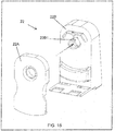
- FIG. 16 shows an exploded perspective view of the pusher housing 22B and the Rotierarms 22A, wherein the locking tabs 22B1 are clearly visible than in the previous figures.
- the pusher 22 can be mounted on the locking tabs 22B1 by pressing the rotating arm 22A with the rotary arm 22A locked to the pusher housing 22B.
- FIG. 17 shows a rear view of the pusher 22, wherein a recess in the back of the pusher housing 22 B receives a flat coil spring 23.
- One end of the spring 23 extends through one of the slots 22C, so that the coil spring 23 is unwound when the pusher 22 is pressed toward the back 14 of the merchandise display base 11.
- the coil spring 23 is biased toward the front of the goods presentation base 11.
- FIGS. 18 to 21 show an embodiment of a connection between the end of the spring 23 and the end cap 16 of the merchandise display base 11.
- the spring 23 may have at its end a notched tongue 23A engageable with a slot 16A in the end cap 16 by rotation of the pusher 22 is inserted into the slot 22 that the narrow portions of the grooved tongue 23 A in the slot 16 A are joined (see FIGS. 19 and 20 ).
- the pusher 22 is rotated back to its original position to attach it to the merchandise presentation base thereby locking the tongue 23A in the slot 16A.
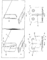
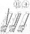
- FIGS. 22 to 24 show the joining of the pusher bar 19 at the Pusherbahn 18.
- the spring 23 is attached to the end cap 16 as described above with respect to FIGS FIGS. 18 to 21 has been described.
- the push bar 19 can then pass through the channel 27 (see FIG. 8 ), which is formed by the inwardly directed sidebars 25.
- the pusher bar 19 is lowered with the mounted pusher 22 on the Pusherbahn 18, wherein the pusher bar 19 in the in FIG. 24 shown position with the Pusherbahn 18 locked (locking means).
- the pusher bar 19 is clipped into the pusher track 18 so that it snaps there by appropriate Formations are provided on the bottom of the pusher bar 19 and on the Pusherbahn 18.
- Such forms are exemplary in the FIGS. 25 and 26 shown.
- the latching strips 19A may extend in sections or over the entire length of the pusher strip 19. If the pusher bar 19 is produced, for example, by extrusion, in particular extruded aluminum, the in FIG. 25 shown used for the extruder.
- the pusher bar 19 made of plastic, in particular thermoplastic, formed and the cross section according to FIG.
- the pusher track 18 may have two opposing inwardly projecting tabs 18A which cooperate with the latch tabs 19A of the pusher bar 19 to lock them together.
- the push bar 19 can be assembled by pressing the pusher bar 19 in the Pusherbahn 18 with this, so that the corresponding latching strips 19A, 18A interlock to lock the pusher bar 19 on the Pusherbahn 18.
- FIG. 26 A composite cross-sectional view of the pusher bar 19 and the pusher track 18 is shown in FIG FIG. 26 shown.
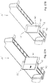
- FIGS 27A and 27B show a goods presentation unit 10 'with an alternative pusher 22', which is designed like the pusher 22 described above with the exception of the formation of an expansion surface, which is formed in the embodiment shown here as an extension plate 40, the side of a in Figure 27B shown position with a minimal pusher surface into one Figure 27A shown position can be pulled out with a maximum pusher surface.
- the pusher 22 ' has a corresponding to the extension plate 40 Receiving channel, wherein the maximum extraction position according to Figure 27A is realized by a stop, not shown.
- the pusher 22 On its underside in the direction of the front end cap 16 arranged support 41, so that a voltage applied to the pusher product packaging is not only applied to the pusher surface, but also rests on the support surface 41.
- the support surface 41 has in particular at the front lower edge of a chamfer 42 which abuts in a maximum retracted position in the direction of the front end cap 16 on a counter to the chamfer 42 corresponding inclined surface 42 to limit the maximum feed of the pusher 22 '.
- the goods presentation unit 10 can be fastened to a front strip 24 which permits a lateral movement of the goods presentation unit 10 in order to be able to receive additional goods presentation units of different width and configuration.
- FIG. 27 an embodiment of the merchandise display unit 10 is shown mounted on the front panel 24, the end cap 16 having means for holding the merchandise display unit 10 on the front panel 24 while allowing lateral movement along the front panel 24 transversely to the length of the merchandise display unit 10.
- the end cap 16 has an upwardly directed projection 16A which fits into a corresponding groove 24A on the front panel 24.
- the projection 16A and the groove 24A are the only holding elements for fixing the goods display unit 10 to the front panel 24.
- the projection 16A is activated by raising / tilting the goods display unit 10 the rear barrier is inserted into the groove 24A and fixed by lowering the merchandise display unit 10, the merchandise display unit 10 being held by the weight of the merchandise display unit 10 and, optionally, the product packages stored thereon.
- the goods presentation unit 10 in the simplest way with the front panel 24 can be mounted.
- FIG. 30 shows a non-inventive example of a goods display unit 10 with a gravity-operated front barrier or door as in relation to FIGS. 1 to 7 described.
- the Pusherbahn 18 has in the present case a roller conveyor 32 with a plurality of rollers 32A. This is fixed at its front end to a front panel 34. A separator 12A can be fixed to the front strip 34. A pusher is not needed. A rear barrier 29 may be disposed at a selected position along the length of the row separator 12A, so that the depth of the product row may be restricted.
- the roller conveyor 32 can be mounted so that it is inclined in the direction of the front panel 34, that has a slope.
- the gravity-operated door or barrier 20 may be fixed to the front panel 34 and may have means that the door or barrier 20 is self-closing after product packages have been inserted through the door or barrier 20 into the product line.
Landscapes
- Freezers Or Refrigerated Showcases (AREA)
Description
- Die vorliegende Erfindung betrifft eine Warenpräsentationseinheit gemäß Anspruch 1
- Die vorliegende Offenbarung betrifft das Gebiet der Einzelhandelsproduktlagerungs- und -präsentationseinheiten. Genauer gesagt betrifft die Offenbarung Einzelhandelswarenpräsentationseinheiten, bei welchen die Produktverpackungen oder -bündel von einem vorderen Ende der Präsentationseinheit beladen werden.
- Die
US 2008/156752 A1 ,WO 2015/191398 A1 ,US 2005/077259 A1 ,US 2007/158281 A1 ,WO 96/25074 A1 US 6 142 317 A WO 02/089104 A2 US 2014/190917 A1 zeigen bekannte Fördereinrichtungen für Waren. - Warenpräsentationseinheiten sind insbesondere als modulare Warenpräsentationseinheiten bekannt, die an einem Regal einzeln, Seite an Seite oder vertikal getrennt voneinander montiert werden können. Die Produktverpackungen oder -bündel können durch Schwerkraft zu einem vorderen Ende der Warenpräsentationseinheit getrieben werden, wobei beispielsweise ein Boden mit Gefälle und einer Vielzahl von Rollen verwendet werden kann, so dass der Antrieb allein durch die Schwerkraft realisiert wird. Am vorderen Ende werden die Produktverpackungen durch eine Barriere gehalten. Sobald eine Produktverpackung entnommen wird, werden die verbleibenden Produktverpackungen durch Schwerkraft in Richtung der Barriere gedrängt.
- Andere Arten von Warenpräsentationseinheiten verwenden eine vorgespannte Platte oder einen Pusher, der die hinterste Produktverpackung kontaktiert und alle auf der Warenpräsentationseinheit in einer Reihe angeordneten Verpackungen zum vorderen Ende der Warenpräsentationseinheit drängt.
- Bei einigen Konfigurationen werden die Warenpräsentationseinheiten von oben beladen. Im Falle von schwerkraftbetriebenen Warenpräsentationseinheiten werden die Produktverpackungen einfach auf den Boden der Warenpräsentationseinheit gestellt. Bei pusher-betriebenen Warenpräsentationseinheiten wird der Pusher nach hinten bewegt und Produktverpackungen in den Raum zwischen der Barriere und den Pusher eingesetzt. Anschließend wird der Pusher in Betrieb gesetzt.
- Aufgabe der vorliegenden Erfindung ist es, eine einfacher zu handhabende Warenpräsentationseinheit vorzusehen, bei der die Produktverpackungen effizient an das vordere Ende der Warenpräsentationseinheit gedrängt werden.
- Diese Aufgabe wird mit den Merkmalen des Anspruchs 1 gelöst. Vorteilhafte Weiterbildungen der Erfindung sind in den Unteransprüchen angegeben.
- Der Erfindung liegt der Gedanke zugrunde, eine Warenpräsentationseinheit vorzusehen, bei der eine Warenpräsentationsbasis modular mit einer Pusherbahn ausgebildet ist, die durch Rastmittel mit einer Pusherleiste zur Verrastung mit einem Pusher ausgebildet ist und/oder die an einem vorderen Ende der Warenpräsentationsbasis zumindest eine schwerkraftbetriebene Barriere aufweist, die um eine im Wesentlichen senkrecht zur Ebene der Pusherbahn verlaufende Achse rotierbar ausgebildet ist. Die vorbeschriebenen Alternativen sollen insbesondere als eigenständige Erfindungen und in Kombination mit jedem der nachfolgend beschriebenen Merkmale offenbart gelten.
- Gemäß einem alternativen, insbesondere eigenständigen oder mit den vorliegend offenbarten Erfindungsaspekten kombinierbaren, Erfindungsaspekt, weist die Warenpräsentationseinheit zumindest einen mit der Pusherleiste montierbaren, entlang der Pusherleiste geführten und bis zur vorderen Endkappe bewegbaren Pusher auf. Dieser ist vorzugsweise federbetätigt, insbesondere mittels einer Schraubenfeder, wobei die vordere Endkappe vorzugsweise eine Haltenut für eine am Ende der Schraubenfeder angeordnete Zunge aufweist, und wobei der zumindest eine Pusher vorzugsweise an seinem Boden nach Innen gerichtete Seitenleisten aufweist, welche einen Kanal zum Einsetzen der Pusherleiste definieren.
- Gemäß einem weiteren, insbesondere eigenständigen oder mit den vorliegend offenbarten Erfindungsaspekten kombinierbaren, Erfindungsaspekt wird eine Warenpräsentationseinheit mit einem Pusher offenbart, der eine einstellbare Pusherfläche aufweist. Mit einstellbar ist insbesondere die Größe der Pusherfläche und/oder die Form der Pusherfläche gemeint, insbesondere durch Ausklappen oder Ausfahren eines, vorzugsweise als Rotierarm ausgebildeten, beweglich am Pusher angeordneten Bauteils. Das Bauteil ist vorzugsweise mit dem Pushergehäuse verrastet oder verrastbar.
- Gemäß einer Weiterbildung der Warenpräsentationseinheit weist diese zumindest einen Produktreihentrenner auf, der sich insbesondere in eine Richtung parallel zu der zumindest einen Pusherbahn und/oder in einer Ebene im Wesentlichen senkrecht zur Ebene der zumindest einen Pusherbahn erstreckt. Vorzugsweise ist der zumindest eine Produktreihentrenner mit der zumindest einen Pusherbahn und der vorderen Endkappe als Einheit, insbesondere untrennbar und/oder aus einem einzigen Werkstoff, gebildet. Erfindungsgemäß weist die Warenpräsentationseinheit eine hintere Barriere an einem längsseitigen Ende der zumindest einen Pusherbahn gegenüber der vorderen Endkappe auf. In Weiterbildung der vorliegenden Erfindung sind die Pusherbahn, die vordere Endkappe und die hintere Barriere als Einheit, vorzugsweise untrennbar und/oder aus einem einzigen Werkstoff, gebildet.
- Gemäß einem weiteren, vorteilhaften Aspekt der vorliegenden Erfindung weist die vordere Endkappe Montagemerkmale zur Fixierung/Sicherung der vorderen Endkappe an einer sich in einer Richtung quer zur Länge der zumindest einen Pusherbahn erstreckenden Frontleiste auf.
- In Weiterbildung der vorliegenden Erfindung weist die Warenpräsentationseinheit insbesondere Mittel zum Drängen der Produktverpackungen längs der Warenpräsentationsbasis in Richtung der vorderen Endkappe auf. Die Mittel zum Drängen weisen insbesondere eine Rollenbahn mit einer Vielzahl von Rollen auf. Die Rollenbahn ist vorzugsweise geneigt, insbesondere mit einem Gefälle, so dass die Schwerkraft die Produktverpackungen in Richtung der Schwerkraft betätigten Barriere drängend ausgebildet ist.
- Soweit in der obigen Beschreibung Verfahrensmerkmale offenbart sind, sollen diese auch vorrichtungsgemäß offenbart gelten oder als Verfahren beanspruchbar sein.
- Weitere Vorteile, Merkmale und Einzelheiten der Erfindung ergeben sich aus der nachfolgenden Beschreibung bevorzugter Ausführungsbeispiele sowie anhand der Zeichnung. Diese zeigt in:
- Figur 1
- eine Warenpräsentationsbasis mit einer schwerkraftbetriebenen Frontbarriere gemäß einer Ausführungsform der Erfindung,
- Figur 2
- Pusherleisten zur Verwendung mit einer Ausführungsform der Warenpräsentationseinheit,
- Figur 3
- eine Ausführungsform einer montierten Warenpräsentationseinheit mit zwei Produktbehälterreihen, jede mit einem Pusher, um die Produktbehälter in Richtung einer Barriere am vorderen Ende der Warenpräsentationseinheit zu drängen,
- Figur 4
- Teile einer Ausführungsform eines Pushers zur Verwendung mit einer Ausführungsform der Warenpräsentationseinheit,
- Figur 5
- eine Expositionsansicht einer Ausführungsform einer schwerkraftbetriebenen Frontbarriere,
- Figur 6
- eine perspektivische Ansicht einer doppelseitigen, schwerkraftbetriebenen Frontbarriere in einem geschlossenen Zustand,
- Figur 7
- eine Ansicht der Barriere gemäß
Figur 6 in einem geöffneten Zustand zum Einführen einer Produktverpackung, - Figur 6A
- eine alternative Ausführungsform einer Frontbarriere mit einer Rücksetzfeder,
- Figur 7A
- eine perspektivische Detailansicht der Ausführungsform gemäß
Figur 6A in einem geöffneten Zustand der Frontbarriere, - Figur 8
- eine Vorderansicht der Ausführungsform gemäß
Figur 3 in geschlossenem Zustand der schwerkraftbetriebenen Barriere, - Figur 9
- eine Vorderansicht gemäß
Figur 8 in geöffnetem Zustand der Frontbarriere, - Figur 10
- eine perspektivische Ansicht einer Ausführungsform der vorliegenden Erfindung mit einstellbaren Pushern in einer minimalen Flächenstellung,
- Figur 11
- eine Ansicht der Ausführungsform gemäß
Figur 10 mit einer maximalen Flächenstellung mit maximaler Breitenausdehnung, - Figur 12
- eine Ansicht der Ausführungsform gemäß
Figur 10 mit einer maximalen Flächeneinstellung mit maximaler Höhe, - Figur 13
- eine perspektivische Detailansicht des Pushers gemäß
Figuren 10 bis 12 , - Figur 14
- eine geschnittene Seitenansicht der Ausführungsform gemäß
Figur 13 , - Figur 15
- eine geschnittene Frontansicht der Ausführungsform gemäß
Figur 13 mit einer Rastnase und einem Zahnrad, - Figur 16
- eine perspektivische Expositionsdarstellung einer Ausführungsform des Pushers,
- Figur 17
- eine perspektivische Darstellung eines Pushers mit einer Schraubenfeder,
- Figur 18 bis Figur 21
- Montageschritte zur Montage der Ausführungsformen gemäß
Figur 17 mit einer Warenpräsentationseinheit, - Figuren 22 bis 24
- perspektivische Darstellungen zur Montage einer Ausführungsform der Produktleiste mit einer Ausführungsform einer Warenpräsentationsbasis,
- Figuren 25 und 26
- eine Querschnittsdarstellung einer Montage einer Ausführungsform einer Pusherleiste mit einer Pusherbahn,
- Figuren 27A und 27B
- eine alternative Ausführungsform von Pushern,
- Figuren 28 und 29
- eine alternative Ausführungsform einer erfindungsgemäßen Warenpräsentationseinheit mit Montageschritten zur Montage an einer Frontleiste, und
- Figur 30
- eine perspektivische Darstellung einer Ausführungsform einer Warenpräsentationseinheit.
- In den Figuren sind gleiche Bauteile oder Bauteile mit der gleichen Funktion mit den gleichen Bezugszeichen gekennzeichnet.
-
Figur 1 zeigt eine perspektivische Ansicht einer Ausführungsform einer Warenpräsentationseinheit mit einer Warenpräsentationsbasis 11 gemäß nachfolgender Beschreibung. Die Warenpräsentationsbasis 11 weist insbesondere zumindest eine Pusherbahn 18 auf, die sich insbesondere von einer vorderen Endkappe 16 zu einer hinteren Barriere 14 erstreckt. Ein Produktreihentrenner 12 kann an der Warenpräsentationsbasis 11 angebracht sein und in einer Ebene im Wesentlichen senkrecht zur Ebene der Pusherbahn 18 ausgerichtet sein/werden. Bei der gezeigten Ausführungsform ist eine zweite Pusherbahn 18 an der gegenüberliegenden Seite des Produktreihentrenners 12 angeordnet. Die zweite Pusherbahn 18 kann, insbesondere am Rand eines Regals, weggelassen werden/entfallen. Weiterhin kann eine schwerkraftbetätigte Frontbarriere 20 an einer Achse montiert sein, die im Wesentlichen senkrecht zur Ebene der Pusherbahn 18 und/oder parallel zu dem Produktreihentrenner 12 verläuft. Die Frontbarriere 20 kann einen oder zwei schwerkraftbetätigte Frontbarrieretüren aufweisen, die weiter unten in Bezug aufFigur 5 erläutert werden. Die Warenpräsentationsbasis 11, insbesondere mit Ausnahme der Frontbarriere 20, kann als Einzelteil, insbesondere durch Spritzgießen aus einem geeigneten Kunststoff, vorzugsweise einem, bevorzugt schlagzähen, Acrylnitril-Butadien-Styrol oder einem anderen geeigneten Kunststoff mit entsprechenden mechanischen Eigenschaften gebildet werden. -
Figur 2 zeigt Beispiele einer Pusherleiste 19, die in den entsprechenden Pusherbahnen 18 eingeclipst werden können, um einen entsprechenden Pusher 22 (sieheFigur 3 ) an die Warenpräsentationsbasis 11 zu montieren. Die Pusherleiste 19 wird in Bezug auf dieFiguren 20 bis 24 detailliert erläutert und kann insbesondere aus Metall, vorzugsweise aus Aluminium, oder aus Kunststoff geformt sein oder aus einem anderen Material mit geeigneten mechanischen Eigenschaften ausgebildet werden. -
Figur 3 zeigt eine perspektivische Ansicht einer zusammengesetzten Warenpräsentationseinheit 10, einschließlich zweier Pusher 22 und einer zwei Platten aufweisenden Frontbarriere 20, die mit der Warenpräsentationsbasis 11 zusammengesetzt ist. -
Figur 4 zeigt eine Explosionsansicht einer beispielhaften Ausführungsform eines Pushers 22 mit einstellbarer Pusherfläche. Der Pusher kann einen rotierbaren Rotierarm 22A mit einer Produktkontaktfläche aufweisen. Produktkontaktfläche ist die Fläche des Pushers 22, die in Richtung der vorderen Endkappe 16 beziehungsweise in eine Warenvorschubrichtung weist. Weiterhin weist der Pusher 22 ein Pushergehäuse 22B auf, an welchem der Rotierarm 22A montiert werden kann. Eine beispielhafte Ausführungsform des Pushers 22 wird detailliert in Bezug auf dieFiguren 10 bis 16 beschrieben. -
Figur 5 zeigt eine Explosionsansicht einer Ausführungsform einer schwerkraftbetriebenen Frontbarriere 20, die zumindest eine (erste) schwerkraftbetätigte Barrieretüre 20C aufweist, die mittels eines Scharnierbolzens 20B rotierbar an der Warenpräsentationsbasis 11 angebracht ist. Weiterhin kann die Frontbarriere 20 eine zweite schwerkraftbetätigte Barrieretüre 20A aufweisen, die rotierbar an der Warenpräsentationsbasis 11 angeordnet ist, insbesondere unter Verwendung desselben Scharnierbolzens 20B. Die erste Barrieretür 20C kann ein schräges Gelenk 20C1 aufweisen, dass mit einem Scharnier 20A2 an der zweiten Barrieretür 20A zusammenwirkt, so dass die erste Barrieretür 20C entlang der Achse des Scharnierbolzens 20B angehoben wird, wenn die erste Barrieretür 20C rotiert wird, wobei die Ebene der ersten Barrieretür 20C in Richtung der Ebene des Produktreihentrenners 20 bewegt wird (siehe Pfeil inFigur 6 ). Auf diese Weise wird die Schwerkraft dafür sorgen, dass die erste Barrieretür 20C in die geschlossene Position gemäßFigur 1 rotiert. Die zweite Barrieretür 20A kann ein entsprechendes schräges Gelenk 20A1 aufweisen, das mit dem Gelenk 20C2 an der ersten Barrieretür 20C zusammenwirkt, um die zweite Schwerkraftschließfunktion gemäß der ersten Barrieretür 20C zu verwirklichen. Bei einigen Ausführungsformen, insbesondere am Rand eines Regals, kann auch nur eine einzige (erste) Barrieretür 20C verwendet werden. In diesem Fall können Merkmale an den Scharnierbolzen 20B korrespondierend zu dem Gelenk 20A2 der zweiten Barrieretür vorgesehen sein, um das Schräggelenk 20C1 festzulegen und um das Schwerkraftschließen der ersten Barrieretür 20C zu verwirklichen. - In einer alternativen Ausführungsform können die erste Barrieretür 20C und/oder die zweite Barrieretür 20A, insbesondere durch Gießen, so gewichtet sein, dass sie eine geeignete Form und/oder Gewichtsverteilung in dem Barrieretürmaterial aufweisen, dass die Schwerkraft die Barrieretüren zum Schließen drängt (auch ohne Installation eines Schräggelenks 20C1/20A1), wobei die Barrieretüren vorzugsweise gelenkig mit der Warenpräsentationsbasis gekoppelt sind, die vorzugsweise in Richtung der Barrieretüren geneigt ist.
-
Figur 6 zeigt eine perspektivische Detailansicht einer doppelseitigen, schwerkraftbetätigten Frontbarriere 20. Die erste Barrieretür 20C und die zweite Barrieretür 20A sind in einer geschlossenen Position gezeigt, so dass Produktbehälter daran gehindert werden, von der Warenpräsentationsbasis 11 herunterzufallen, obwohl sie durch Schwerkraft oder Pusher in Richtung der vorderen Endkappe 16 gedrängt werden.Figur 6 zeigt außerdem den Trenner 12 und eine der Pusherleisten 19 sowie die vordere Endkappe 16.Figur 7 zeigt eine ähnliche Ansicht gemäßFigur 6 , wobei die Barrieretüren 20C und 20A in einer geöffneten Position angeordnet sind. Um die Barrieretüren 20A, 20C zu öffnen reicht es gemäß der gezeigten Ausführungsform aus, die Produktverpackung durch die jeweilige Barrieretür 20A, 20C in Richtung der hinteren Barriere der Warenpräsentationsbasis 11 zu schieben. Sobald die Produktverpackung durch die Barrieretüren 20A, 20C hindurchbewegt wurde, werden die Barrieretüren durch Schwerkraft in die inFigur 6 gezeigte geschlossene Position zurückbewegt, so dass die Produktverpackungen durch die von der Warenpräsentationsbasis 11 und den Trenner 12 gebildeten Produktreihe gehalten werden. Produktverpackungen können entnommen werden, indem sie einzeln oder zusammen über die entsprechende Barrieretür 20A, 20C gehoben werden. - Gemäß einer in den
Figuren 6A und 7A gezeigten alternativen Ausführungsform werden die Frontbarrieretüren 20A, 20C durch eine oder mehrere Federn 20D bei dem Zurückkehren in die geschlossene Position gemäßFigur 6A unterstützt. Die Federn 20D wirken mit dem schrägen Gelenk 20A1, 20C1 zusammen, um die Barrieretür nach unten zu drücken, wobei die Frontbarrieretüren 20A, 20C in die geschlossene Position gedrängt werden. Soweit die Barrieretüren 20A, 20C geöffnet sind, werden die Federn 20D komprimiert, wobei sie eine zusätzliche Kraft in Zusammenwirkung mit den Schräggelenken ausüben, um die Barrieretüren 20A, 20C zu schließen. -
Figur 8 zeigt eine Frontansicht der Warenpräsentationseinheit 10 mit den Barrieretüren 20A, 20C in der geschlossenen Position. Die entsprechenden Pusher 22 sind ebenfalls inFigur 8 dargestellt.Figur 9 zeigt eine Frontansicht der Warenpräsentationseinheit 10, wobei die Barrieretüren 20A, 20C in der geöffneten Position zum Einbringen von Produktverpackungen (nicht gezeigt) angeordnet sind. Weiterhin ist ein Kanal 27 erkennbar, durch welchen die Pusherleiste 19 mit dem Pusher 22 verbunden wird. Der Kanal 27 kann insbesondere durch zwei gegenüberliegende, nach innen weisende Seitenleisten 25 gebildet sein, wobei der Zweck des Kanals 27 weiter unten in Bezug aufFiguren 22 bis 24 detailliert beschrieben wird. - Die
Figuren 10 bis 12 zeigen perspektivische Ansichten einer Ausführungsform der Warenpräsentationseinheit 10, um die Funktion der einstellbaren Flächen der Pusher 22 zu erläutern. Die Einstellbarkeit der Produktkontaktflächen der Pusher 22 dient dazu, Produktverpackungen unterschiedlicher Größe optimal zu den Barrieretüren 20A, 20C zu drängen, ohne dass die Produktverpackungen beschädigt, durcheinandergebracht und/oder geklemmt werden. InFigur 12 befindet sich der Rotierarm 22A in einer geschlossenen Position relativ zu dem Pushergehäuse 22B, um die Kontaktfläche des Pushers für kleinere Produktverpackungen zu minimieren. InFigur 11 sind die Rotierarme 22A in einer horizontalen Lage, um die Breite der Kontaktfläche des Pushers 22 zu maximieren, um breite Produktverpackungen optimal in Richtung der Frontbarrieretüren 20A, 20C zu schieben. InFigur 12 sind die Rotierarme 22A in einer entgegen der geschlossenen Position gemäßFigur 10 orientierten Position oder nach oben angeordnet, um hohe Produktverpackungen besonders gut nach vorne zu schieben. Wie in Bezug aufFiguren 13 bis 16 weiter erläutert, können die Rotierarme 22A auch in anderen Richtungen als die drei beispielhaft inFiguren 10 bis 12 gezeigten Richtungen orientiert werden, um verschiedene Verpackungstypen optimal zu beaufschlagen. -
Figur 13 zeigt eine Frontansicht einer Ausführungsform eines Pushers 22. Der Pusher 22 kann aus zwei verschiedenen Komponenten, insbesondere dem Rotierarm 22A und dem Pushergehäuse 22B, gebildet sein. Am Boden des Pushergehäuses 22B können insbesondere zumindest eines und im vorliegenden Ausführungsbeispiel zwei Federaufnahme 22C vorgesehen sein, von welchen sich eine Feder (sieheFigur 17 ) erstrecken kann, um eine Federkraft auf den Pusher 22 in Richtung der Frontbarriere 20 auszuüben. -
Figur 14 zeigt eine geschnittene Seitenansicht des Pushers gemäßFigur 13 . Das Pushergehäuse 22B weist insbesondere Rastlaschen 22B1 auf, die in einem kreisförmigen Muster (sieheFigur 16 ) angeordnet sind, um den Rotierarm 22A am Pushergehäuse 22B zu halten. Der Rotierarm 22A kann insbesondere eine kreisförmige Öffnung 22A1 aufweisen, um die Rastlaschen 22B1 festzulegen und eine Rotation des Rotierarms 22A um die Achse der Rastlaschen 22B1 zu ermöglichen. -
Figur 15 zeigt eine beispielhafte Ausführungsform des Rotierarms 22 mit einem Zahlrad 22A2, das als einzelne Einheit mit einem Rotierarm 22A ausgebildet sein kann. Das Zahnrad 22A2 legt einen Rastbolzen 22B2 fest, der als Einheit mit dem Pushergehäuse 22 ausgebildet sein kann. Der Rastbolzen 22B2 (ebenso wie das Pushergehäuse 22) kann aus einem Material gebildet werden, das insoweit federnd ausgebildet ist, dass das Zahnrad 22A2 durch den Rastbolzen 22B2 in einer gewählten Rotationsposition gehalten wird, wobei insbesondere eine Rotation des Rotierarms 22A mittels Handkraft ermöglicht wird. -
Figur 16 zeigt eine perspektivische Explosionsdarstellung des Pushergehäuses 22B und des Rotierarms 22A, wobei die Rastlaschen 22B1 deutlicher erkennbar sind als in den vorherigen Figuren. Der Pusher 22 kann durch Drücken des Rotierarms 22A auf die Rastlaschen 22B1 montiert werden, wobei der Rotierarm 22A mit dem Pushergehäuse 22B verrastet.Figur 17 zeigt eine Rückansicht des Pushers 22, wobei eine Ausnehmung in der Rückseite des Pushergehäuses 22B eine flache Schraubenfeder 23 aufnimmt. Ein Ende der Feder 23 erstreckt sich durch einen der Schlitze 22C, so dass die Schraubenfeder 23 abgewickelt wird, wenn der Pusher 22 in Richtung der Rückseite 14 der Warenpräsentationsbasis 11 gedrückt wird. Hierbei wird die Schraubenfeder 23 in Richtung der Front der Warenpräsentationsbasis 11 vorgespannt. - Die
Figuren 18 bis 21 zeigen eine Ausführungsform einer Verbindung zwischen dem Ende der Feder 23 und der Endkappe 16 der Warenpräsentationsbasis 11. Die Feder 23 kann an ihrem Ende eine Kerbzunge 23A aufweisen, die in einen Schlitz 16A in der Endkappe 16 eingreifen kann, indem der Pusher 22 durch Rotation so in den Schlitz 22 gefügt wird, dass die schmalen Abschnitte der genuteten Zunge 23A in den Schlitz 16A gefügt werden (sieheFiguren 19 und 20 ). In der inFigur 21 gezeigten Position ist der Pusher 22 in seine Ursprungsposition zurück rotiert, um ihn mit der Warenpräsentationsbasis zu fügen und dadurch die Zunge 23A in dem Schlitz 16A einzurasten. - Die
Figuren 22 bis 24 zeigen das Fügen der Pusherleiste 19 an der Pusherbahn 18. InFigur 22 ist die Feder 23 an der Endkappe 16 befestigt, wie es oben in Bezug auf dieFiguren 18 bis 21 beschrieben wurde. Die Pusherleiste 19 kann dann durch den Kanal 27 (sieheFigur 8 ) eingesetzt werden, der durch die nach Innen gerichteten Seitenleisten 25 gebildet ist. InFigur 23 wird die Pusherleiste 19 mit dem darauf montierten Pusher 22 auf die Pusherbahn 18 abgesenkt, wobei die Pusherleiste 19 in der inFigur 24 gezeigten Position mit der Pusherbahn 18 verrastet (Rastmittel). - Bei der gezeigten Ausführungsform wird die Pusherleiste 19 in die Pusherbahn 18 eingeclipst, so dass diese dort verrastet, indem geeignete Ausformungen am Boden der Pusherleiste 19 und auf der Pusherbahn 18 vorgesehen sind. Solche Ausformungen sind beispielhaft in den
Figuren 25 und 26 dargestellt. GemäßFigur 25 kann die Pusherleiste 19 am Boden zwei gegenüberliegend nach außen vorstehende Raststreifen 19A aus aufweisen, die am Boden der Pusherleiste 19 angeformt sein können. Die Raststreifen 19A können sich abschnittsweise oder über die gesamte Länge der Pusherleiste 19 erstrecken. Falls die Pusherleiste 19 beispielsweise durch Extrusion, insbesondere extrudiertes Aluminium, hergestellt wird, kann die inFigur 25 gezeigte Form für den Extruder verwendet werden. Bei anderen Ausführungsformen kann die Pusherleiste 19 aus Kunststoff, insbesondere thermoplastisch, gebildet und der Querschnitt gemäßFigur 25 kann für die Gussform verwendet werden. Bei der oben beschriebenen Ausführungsform kann die Pusherbahn 18 zwei gegenüberliegende, nach Innen gegenüberliegend vorstehende Streifen 18A aufweisen, die mit den Raststreifen 19A der Pusherleiste 19 zusammenwirken, um diese aneinander festzusetzen. Somit kann die Pusherleiste 19 durch Drücken der Pusherleiste 19 in die Pusherbahn 18 mit dieser zusammengesetzt werden, so dass die korrespondierenden Raststreifen 19A, 18A ineinandergreifen, um die Pusherleiste 19 an der Pusherbahn 18 zu verrasten. Eine zusammengesetzte Querschnittsansicht der Pusherleiste 19 und der Pusherbahn 18 ist inFigur 26 gezeigt. - Die
Figuren 27A und 27B zeigen eine Warenpräsentationseinheit 10' mit einem alternativen Pusher 22', der wie der oben beschriebene Pusher 22 ausgebildet ist mit Ausnahme der Ausbildung einer Erweiterungsfläche, die beim hier gezeigten Ausführungsbeispiel als Erweiterungsplatte 40 ausgebildet ist, die seitlich aus einer inFigur 27B gezeigten Position mit einer minimalen Pusherfläche bis in eineFigur 27A gezeigte Position mit einer maximalen Pusherfläche ausgezogen werden kann. Hierfür weist der Pusher 22' einen zur Erweiterungsplatte 40 korrespondierenden Aufnahmekanal auf, wobei die maximale Auszugsposition gemäßFigur 27A durch einen nicht dargestellten Anschlag realisiert wird. - Weiterhin weist der Pusher 22' an seiner Unterseite in Richtung der vorderen Endkappe 16 angeordnete Auflage 41 auf, so dass eine am Pusher anliegende Produktverpackung nicht nur an der Pusherfläche anliegt, sondern auch auf der Auflagefläche 41 aufliegt.
- Die Auflagefläche 41 weist insbesondere an der vorderen Unterkante eine Fase 42 auf, die in einer maximal eingezogenen Position in Richtung der vorderen Endkappe 16 an einem gegenläufig zur Fase 42 korrespondierenden Schrägfläche 42 anschlägt, um den maximalen Vorschub des Pushers 22' zu begrenzen.
- Gemäß einer weiteren Ausführungsform kann die Warenpräsentationseinheit 10 an einer Frontleiste 24 befestigt sein, die eine laterale Bewegung der Warenpräsentationseinheit 10 zulässt, um zusätzliche Warenpräsentationseinheiten unterschiedlicher Breite und Konfiguration aufnehmen zu können.
- In
Figur 27 ist eine Ausführungsform der Warenpräsentationseinheit 10 gezeigt, die an der Frontleiste 24 montiert ist, wobei die Endkappe 16 Mittel zum Halten der Warenpräsentationseinheit 10 an der Frontleiste 24 aufweist, während eine laterale Bewegung entlang der Frontleiste 24 transversal zur Länge der Warenpräsentationseinheit 10 ermöglicht wird. - Gemäß
Figur 28 weist die Endkappe 16 einen nach oben gerichteten Vorsprung 16A auf, der in eine korrespondierende Nut 24A an der Frontleiste 24 passend einsetzbar ist. Vorzugsweise sind der Vorsprung 16A und die Nut 24A die einzigen Halteelemente zur Fixierung der Warenpräsentationseinheit 10 an der Frontleiste 24. Der Vorsprung 16A wird durch Anheben/Schrägstellung der Warenpräsentationseinheit 10 an der hinteren Barriere in die Nut 24A eingeführt und durch Absenken der Warenpräsentationseinheit 10 fixiert, wobei die Warenpräsentationseinheit 10 durch das Gewicht der Warenpräsentationseinheit 10 und gegebenenfalls den darauf gelagerten Produktverpackungen gehalten wird. Somit ist die Warenpräsentationseinheit 10 auf einfachste Weise mit der Frontleiste 24 montierbar. -
Figur 30 zeigt ein nicht erfindungsgemäßen Beispiel einer Warenpräsentationseinheit 10 mit einer schwerkraftbetriebenen Frontbarriere oder Türe wie in Bezug auf dieFiguren 1 bis 7 beschrieben. Die Pusherbahn 18 weist im vorliegenden Fall eine Rollenbahn 32 mit einer Vielzahl von Rollen 32A auf. Diese ist an ihrem vorderen Ende an einer Frontleiste 34 fixiert. Ein Trenner 12A ist an der Frontleiste 34 fixierbar. Ein Pusher wird dagegen nicht benötigt. Eine hintere Barriere 29 kann an einer ausgewählten Position entlang der Länge des Reihentrenners 12A angeordnet werden, so dass die Tiefe der Produktreihe beschränkt werden kann. Die Rollenbahn 32 kann so montiert werden, dass sie in Richtung der Frontleiste 34 geneigt ist, also ein Gefälle aufweist. Die schwerkraftbetätigte Tür oder Barriere 20 kann an der Frontleiste 34 fixiert werden und Mittel aufweisen, dass die Tür oder Barriere 20 selbstschließend ist, nachdem Produktpackungen durch die Tür oder Barriere 20 in die Produktreihe eingesetzt worden sind. -
- 10
- Warenpräsentationseinheit
- 11
- Warenpräsentationsbasis
- 12
- Produktreihentrenner
- 14
- hintere Barriere
- 16
- vordere Endkappe
- 16A
- Vorsprung
- 18
- Pusherbahn
- 19
- Pusherleiste
- 20
- Frontbarriere
- 20A
- Scharniertüren
- 20A2
- Gelenk
- 20B
- Scharnierbolzen
- 20C
- Barrieretüre
- 20C1
- schräges Gelenk
- 20C2
- Gelenk
- 20D
- Feder
- 22, 22'
- Pusher
- 22A
- Rotierarm
- 22A1
- Öffnung
- 22A2
- Zahnrad
- 22B
- Pushergehäuse
- 22B1
- Rastlasche
- 22B2
- Rastbolzen
- 22C
- Federschlitz
- 23
- Schraubenfeder
- 23A
- Kerbzunge
- 24
- Frontleiste
- 24A
- Nut
- 25
- Seitenleisten
- 32
- Rollenbahn
- 32A
- Rollen
- 34
- Frontleiste
- 40
- Schubplatte
- 41
- Auflage
- 42
- Fase
- 43
- Schrägfläche
Claims (11)
- Warenpräsentationseinheit aufweisend:- eine Warenpräsentationsbasis (11) mit einer vorderen Endkappe (16) an einem Längsende der Warenpräsentationsbasis (11),- zumindest eine sich in Längsrichtung der Warenpräsentationsbasis (11) von der vorderen Endkappe (16) zu einer hinteren Barriere (14) erstreckende Pusherbahn (18) mit einem Rastmittel zur Halterung einer Pusherleiste (19) in der Pusherbahn (18), wobei die Pusherleiste (19) ein korrespondierendes Rastmittel aufweist, so dass die Pusherleiste (19) in die zumindest eine Pusherbahn (18) durch Kompression der Pusherleiste (19) gegenüber der zumindest einen Pusherbahn (18) einrastbar oder eingerastet ist,- zumindest einen mit der Pusherleiste (19) montierbaren, entlang der Pusherleiste (19) geführten und bis zur vorderen Endkappe (16) bewegbaren Pusher (22).
- Warenpräsentationseinheit gemäß Anspruch 1, wobei der zumindest eine Pusher (22) eine Pusherseite mit einstellbarer Fläche aufweist.
- Warenpräsentationseinheit nach Anspruch 2, wobei die Pusherseite mit einstellbarer Fläche einen am Pusher (22) montierten Rotierarm (22A) aufweist.
- Warenpräsentationseinheit nach Anspruch 3, wobei der Pusher (22), insbesondere kreisförmig angeordnete, Rastlaschen aufweist, die sich vorzugsweise durch eine Öffnung im Rotierarm (22A) erstrecken.
- Warenpräsentationseinheit nach Anspruch 4, wobei der Rotierarm (22A) oder das Pushergehäuse ein Zahnrad aufweist und das jeweils andere des Pushergehäuses oder Rotierarms (22A) einen Rastbolzen aufweist, so dass der Rotierarm in einer ausgewählten Rotationslage in Bezug auf das Pushergehäuse arretierbar ist.
- Warenpräsentationseinheit gemäß Anspruch 1, weiterhin aufweisend:- zumindest eine im Bereich der vorderen Endkappe (16) angeordnete gravitationsbetriebene Barriere, wobei die zumindest eine gravitationsbetriebene Barriere insbesondere um eine Achse rotierbar ist, die im Wesentlichen senkrecht zu einer Ebene der zumindest einen Pusherbahn (18) in einer Richtung weg von der vorderen Endkappe (16) ausgebildet ist, wobei Produktbehälter durch die schwerkraftbetriebene Barriere durch eine Längsbewegung gegen die zumindest eine schwerkraftbetriebene Barriere einführbar sind.
- Warenpräsentationseinheit gemäß Anspruch 6, wobei die zumindest eine schwerkraftbetriebene Barriere ein auf einem Scharnierbolzen angeordnetes, schräges Scharnier aufweist, wobei das schräge Scharnier mit einem zweiten Scharnier auf dem Scharnierbolzen zusammenwirkt, so dass eine Rotation der zumindest einen schwerkraftbetriebenen Barriere die zumindest eine schwerkraftbetriebene Barriere vertikal von einer Ebene der zumindest eine Pusherbahn (18) anhebt.
- Warenpräsentationseinheit nach Anspruch 7, die zumindest eine mit dem schrägen Scharnier verbundene Feder zur Rückstellung der zumindest einen schwerkraftbetriebenen Barriere, insbesondere nach unten, aufweist.
- Warenpräsentationseinheit nach Anspruch 1, die zumindest einen Produktreihentrenner (12) aufweist, der sich insbesondere in eine Richtung parallel zu der zumindest einen Pusherbahn (18) und/oder in einer Ebene im Wesentlichen senkrecht zur Ebene der zumindest einen Pusherbahn (18) erstreckt, wobei der zumindest eine Produktreihentrenner (12) mit der zumindest einen Pusherbahn (18) und der vorderen Endkappe als Einheit, insbesondere untrennbar und/oder aus einem einzigen Werkstoff, gebildet ist.
- Warenpräsentationseinheit gemäß Anspruch 1, wobei die Pusherleiste (19) am Boden zwei gegenüberliegend nach außen vorstehende Raststreifen (19A) zum Verrasten mit der Pusherbahn (18) aufweist.
- Warenpräsentationseinheit nach Anspruch 1, wobei die Pusherleiste (19) in die Pusherbahn (18) eingeclipst oder einclipsbar ist.
Applications Claiming Priority (1)
| Application Number | Priority Date | Filing Date | Title |
|---|---|---|---|
| US15/013,311 US9668590B1 (en) | 2016-02-02 | 2016-02-02 | Retail product display unit having gravity operated front barrier for product loading |
Publications (2)
| Publication Number | Publication Date |
|---|---|
| EP3202286A1 EP3202286A1 (de) | 2017-08-09 |
| EP3202286B1 true EP3202286B1 (de) | 2018-11-14 |
Family
ID=56842698
Family Applications (1)
| Application Number | Title | Priority Date | Filing Date |
|---|---|---|---|
| EP16186125.7A Not-in-force EP3202286B1 (de) | 2016-02-02 | 2016-08-29 | Warenpräsentationseinheit |
Country Status (2)
| Country | Link |
|---|---|
| US (1) | US9668590B1 (de) |
| EP (1) | EP3202286B1 (de) |
Families Citing this family (17)
| Publication number | Priority date | Publication date | Assignee | Title |
|---|---|---|---|---|
| US8978904B2 (en) | 2005-09-12 | 2015-03-17 | Rtc Industries, Inc. | Product management display system with trackless pusher mechanism |
| US9138075B2 (en) | 2005-09-12 | 2015-09-22 | Rtc Industries, Inc. | Product management display system |
| US11259652B2 (en) | 2005-09-12 | 2022-03-01 | Rtc Industries, Inc. | Product management display system |
| US9173504B2 (en) | 2005-09-12 | 2015-11-03 | Rtc Industries, Inc. | Product management display system |
| US10285510B2 (en) | 2005-09-12 | 2019-05-14 | Rtc Industries, Inc. | Product management display system |
| US11583109B2 (en) | 2005-09-12 | 2023-02-21 | Rtc Industries, Inc. | Product management display system with trackless pusher mechanism |
| US11344138B2 (en) | 2005-09-12 | 2022-05-31 | Rtc Industries, Inc. | Product management display system |
| US10952546B2 (en) | 2005-09-12 | 2021-03-23 | Rtc Industries, Inc. | Product management display system with trackless pusher mechanism |
| US8739984B2 (en) | 2005-09-12 | 2014-06-03 | Rtc Industries, Inc. | Product management display system with trackless pusher mechanism |
| US9955802B2 (en) | 2015-04-08 | 2018-05-01 | Fasteners For Retail, Inc. | Divider with selectively securable track assembly |
| EP3402371B1 (de) * | 2016-01-13 | 2020-03-04 | RTC Industries, Inc. | Warenauslagesystem mit einer spreizschutzvorrichtung |
| WO2018232271A1 (en) | 2017-06-16 | 2018-12-20 | Rtc Industries, Inc. | Product management display system with trackless pusher mechanism |
| US11000132B2 (en) * | 2018-09-14 | 2021-05-11 | Marmon Foodservice Technologies, Inc. | Product display units with pushers |
| US11229302B2 (en) | 2019-08-29 | 2022-01-25 | James CIESICK | Roller rack assembly |
| AU2022405506B2 (en) * | 2021-12-06 | 2025-07-31 | Fasteners For Retail, Inc. | Merchandise security system |
| EP4321057A1 (de) * | 2022-08-12 | 2024-02-14 | POS TUNING GmbH | Vorrichtung zum vorschub von waren |
| US12495915B2 (en) * | 2023-06-07 | 2025-12-16 | Retail Space Solutions Llc | Low-profile product merchandizer systems |
Citations (1)
| Publication number | Priority date | Publication date | Assignee | Title |
|---|---|---|---|---|
| WO2002089104A2 (en) * | 2001-04-26 | 2002-11-07 | Dci Marketing, Inc. | Merchandising system |
Family Cites Families (38)
| Publication number | Priority date | Publication date | Assignee | Title |
|---|---|---|---|---|
| US3110402A (en) * | 1961-03-29 | 1963-11-12 | Cons Cigar Corp | Adjustable display rack |
| US4901869A (en) * | 1988-08-26 | 1990-02-20 | Hawkinson Rodney B | Merchandise display rack of variable size |
| US4930663A (en) * | 1988-10-17 | 1990-06-05 | Unidynamics Corporation | Article alignment unit |
| US5265738A (en) * | 1992-05-14 | 1993-11-30 | P.O.P. Displays, Inc. | Shelf display dispenser for packaged merchandise |
| US5562217A (en) * | 1994-10-31 | 1996-10-08 | The Mead Corporation | Pusher unit for dispensing merchandise |
| US5570811A (en) * | 1994-11-01 | 1996-11-05 | Fawn Engineering Corporation | Apparatus and method for dispensing items from a vending machine |
| US5586687A (en) * | 1995-02-16 | 1996-12-24 | The Mead Corporation | Gravity feed bottle dispensing device having a track-blocking gate mechanism |
| US5634564A (en) * | 1995-06-13 | 1997-06-03 | The Mead Corporation | Pusher device for dispensing articles |
| WO1997008666A1 (en) * | 1995-08-25 | 1997-03-06 | Matsushita Refrigeration Company | Storage device in vending machine |
| US6142317A (en) * | 1997-11-12 | 2000-11-07 | Merl; Milton J. | Gravity feed shelving system with track and pusher |
| US6227385B1 (en) * | 1999-12-03 | 2001-05-08 | Dci Marketing, Inc. | Shelf tray system |
| US20080156752A1 (en) * | 2001-04-26 | 2008-07-03 | Dci Marketing, Inc. | Merchandising System |
| US20050189310A1 (en) * | 2001-04-26 | 2005-09-01 | Dci Marketing, Inc. | Merchandising system |
| US8627965B2 (en) * | 2001-05-17 | 2014-01-14 | Rtc Industries, Inc. | Multi-component display and merchandise systems |
| US8096427B2 (en) * | 2002-05-17 | 2012-01-17 | Rtc Industries, Inc. | Product management display system |
| US6622874B1 (en) * | 2001-11-13 | 2003-09-23 | Terry Hawkinson | Apparatus and method for holding and feeding product |
| US20050218094A1 (en) * | 2002-03-21 | 2005-10-06 | Howerton Gary N | Pusher-type display system |
| US8496126B2 (en) * | 2002-11-18 | 2013-07-30 | Fasteners For Retail, Inc. | Shelving system |
| US6955269B2 (en) * | 2003-10-13 | 2005-10-18 | Display Technologies, Llc | Weighted pusher |
| US7641057B2 (en) * | 2003-10-14 | 2010-01-05 | Fasteners For Retail, Inc. | Adjustable shelving system |
| US20050189369A1 (en) * | 2003-10-17 | 2005-09-01 | Kirk Vlastakis | Theft deterrent system |
| US7201281B1 (en) * | 2003-12-18 | 2007-04-10 | Imageworks Display And Marketing Group | Adjustable modular merchandise pusher system |
| US7506769B2 (en) * | 2004-12-07 | 2009-03-24 | Howerton Gary N | Pusher-type display system |
| CA2609920A1 (en) * | 2005-06-02 | 2006-12-07 | Coin Acceptors, Inc. | Dispenser tray for a vending machine |
| US7628282B2 (en) * | 2005-10-25 | 2009-12-08 | Rtc Industries, Inc. | Product management display system |
| US20080142458A1 (en) * | 2006-12-15 | 2008-06-19 | Excell Products, Inc. | Pusher assembly |
| US7918353B1 (en) * | 2007-02-20 | 2011-04-05 | Henschel-Steinau, Inc. | Display and dispensing apparatus |
| US20090084812A1 (en) * | 2007-09-28 | 2009-04-02 | The Coca-Cola Company | Package Advancement System |
| US8038018B1 (en) * | 2008-03-25 | 2011-10-18 | Vendmore Systems, Llc | Vending machine product stabilizer |
| US20110089125A1 (en) * | 2008-04-16 | 2011-04-21 | Roeske Pauline R | Jar Dispenser |
| US8276766B2 (en) * | 2008-10-09 | 2012-10-02 | Fasteners For Retail, Inc. | Adjustable depth merchandising apparatus |
| US8267258B2 (en) * | 2009-04-24 | 2012-09-18 | Xerox Corporation | Tray assembly |
| US20120048817A1 (en) * | 2010-08-25 | 2012-03-01 | Diageo North America, Inc. | Shelf display device |
| US9016483B2 (en) * | 2010-11-12 | 2015-04-28 | Frito-Lay North America, Inc. | Dual plane self-adjusting shelf |
| US9357856B2 (en) * | 2012-08-03 | 2016-06-07 | Fasteners For Retail, Inc. | Latching system for a merchandising apparatus |
| KR101389747B1 (ko) * | 2013-04-09 | 2014-05-27 | 세대산전 주식회사 | 상품 진열 선반 |
| US9629483B2 (en) * | 2014-04-14 | 2017-04-25 | Fasteners For Retail, Inc. | Rail position lock |
| KR101884007B1 (ko) * | 2014-06-09 | 2018-07-31 | 알티씨 인더스트리즈, 인크. | 제품 관리 디스플레이 시스템 |
-
2016
- 2016-02-02 US US15/013,311 patent/US9668590B1/en active Active
- 2016-08-29 EP EP16186125.7A patent/EP3202286B1/de not_active Not-in-force
Patent Citations (1)
| Publication number | Priority date | Publication date | Assignee | Title |
|---|---|---|---|---|
| WO2002089104A2 (en) * | 2001-04-26 | 2002-11-07 | Dci Marketing, Inc. | Merchandising system |
Also Published As
| Publication number | Publication date |
|---|---|
| US9668590B1 (en) | 2017-06-06 |
| EP3202286A1 (de) | 2017-08-09 |
Similar Documents
| Publication | Publication Date | Title |
|---|---|---|
| EP3202286A1 (de) | Warenpräsentationseinheit | |
| DE69621083T2 (de) | Flaschenspendevorrichtung mit schwerkraftausnutzung sowie einem schienenblockiersystem mit schrankenmechanismus | |
| DE2729151C2 (de) | Sicherheitsgurtverschluß | |
| EP0330192B1 (de) | Rolladen für Öffnungsabschlüsse | |
| DE3247796A1 (de) | Aufbewahrungsvorrichtung fuer scheibenfoermige aufzeichnungstraeger | |
| EP3608261B1 (de) | Hängetaschengestell und hängetasche | |
| DE2731953C2 (de) | ||
| DE10336889A1 (de) | Ablagevorrichtung | |
| DE3905647C2 (de) | ||
| DE212014000219U1 (de) | Vorschubeinrichtung für die automatische Verschiebung von Gegenständen mit Führungselement sowie Bausatz zur Montage einer Vorschubeinrichtung | |
| CH619124A5 (de) | ||
| EP0218020A2 (de) | Ausstell-Schiebedach für Kraftfahrzeuge | |
| DE4326172A1 (de) | Preiskassette | |
| DE3431062C2 (de) | Vorrichtung zum Anbringen einer Preisschild-Trägerschiene an Verkaufsregalen, -vitrinen oder dergleichen | |
| DE3246041A1 (de) | Behaelter zur aufbewahrung von magnetbandkassetten | |
| EP4196413B1 (de) | Transportcontainer zum temperaturgeführten transport von temperatursensiblen gütern | |
| EP1264669A1 (de) | Vorrichtung zum Schneiden von Obst, Gemüse oder dergleichen | |
| DE9117179U1 (de) | Abdeckung, insbesondere plombierbare Abdeckhaube, für Einrichtungen der elektrischen Hausinstallation | |
| DE69220341T2 (de) | Knopfzuführung für eine Knopfansatzmaschine | |
| DE4327203C2 (de) | Vorrichtung zum Archivieren von Kassetten | |
| EP3737262B1 (de) | Anordnung aus ausziehführung und mitnehmer | |
| DE4427026A1 (de) | Schubladenverriegelungsvorrichtung | |
| EP1817981B1 (de) | Vorrichtung zur Führung der Bewegung von relativ zueinander bewegbaren Möbelteilen, insbesondere für Schubladenführungen, sowie Schubladenführung mit einer solchen Vorrichtung | |
| DE9401206U1 (de) | Deckel für einen Behälter | |
| WO2020201459A1 (de) | Warenkorb |
Legal Events
| Date | Code | Title | Description |
|---|---|---|---|
| PUAI | Public reference made under article 153(3) epc to a published international application that has entered the european phase |
Free format text: ORIGINAL CODE: 0009012 |
|
| STAA | Information on the status of an ep patent application or granted ep patent |
Free format text: STATUS: THE APPLICATION HAS BEEN PUBLISHED |
|
| STAA | Information on the status of an ep patent application or granted ep patent |
Free format text: STATUS: REQUEST FOR EXAMINATION WAS MADE |
|
| AK | Designated contracting states |
Kind code of ref document: A1 Designated state(s): AL AT BE BG CH CY CZ DE DK EE ES FI FR GB GR HR HU IE IS IT LI LT LU LV MC MK MT NL NO PL PT RO RS SE SI SK SM TR |
|
| AX | Request for extension of the european patent |
Extension state: BA ME |
|
| 17P | Request for examination filed |
Effective date: 20170720 |
|
| RBV | Designated contracting states (corrected) |
Designated state(s): AL AT BE BG CH CY CZ DE DK EE ES FI FR GB GR HR HU IE IS IT LI LT LU LV MC MK MT NL NO PL PT RO RS SE SI SK SM TR |
|
| STAA | Information on the status of an ep patent application or granted ep patent |
Free format text: STATUS: EXAMINATION IS IN PROGRESS |
|
| 17Q | First examination report despatched |
Effective date: 20171006 |
|
| GRAP | Despatch of communication of intention to grant a patent |
Free format text: ORIGINAL CODE: EPIDOSNIGR1 |
|
| STAA | Information on the status of an ep patent application or granted ep patent |
Free format text: STATUS: GRANT OF PATENT IS INTENDED |
|
| RIC1 | Information provided on ipc code assigned before grant |
Ipc: A47F 5/10 20060101ALI20180509BHEP Ipc: A47F 1/12 20060101AFI20180509BHEP Ipc: A47F 5/00 20060101ALN20180509BHEP |
|
| INTG | Intention to grant announced |
Effective date: 20180529 |
|
| GRAS | Grant fee paid |
Free format text: ORIGINAL CODE: EPIDOSNIGR3 |
|
| GRAA | (expected) grant |
Free format text: ORIGINAL CODE: 0009210 |
|
| STAA | Information on the status of an ep patent application or granted ep patent |
Free format text: STATUS: THE PATENT HAS BEEN GRANTED |
|
| AK | Designated contracting states |
Kind code of ref document: B1 Designated state(s): AL AT BE BG CH CY CZ DE DK EE ES FI FR GB GR HR HU IE IS IT LI LT LU LV MC MK MT NL NO PL PT RO RS SE SI SK SM TR |
|
| REG | Reference to a national code |
Ref country code: CH Ref legal event code: EP Ref country code: AT Ref legal event code: REF Ref document number: 1063802 Country of ref document: AT Kind code of ref document: T Effective date: 20181115 |
|
| REG | Reference to a national code |
Ref country code: DE Ref legal event code: R096 Ref document number: 502016002486 Country of ref document: DE |
|
| REG | Reference to a national code |
Ref country code: IE Ref legal event code: FG4D Free format text: LANGUAGE OF EP DOCUMENT: GERMAN |
|
| REG | Reference to a national code |
Ref country code: SE Ref legal event code: TRGR |
|
| REG | Reference to a national code |
Ref country code: NL Ref legal event code: MP Effective date: 20181114 |
|
| REG | Reference to a national code |
Ref country code: LT Ref legal event code: MG4D |
|
| REG | Reference to a national code |
Ref country code: NO Ref legal event code: T2 Effective date: 20181114 |
|
| PG25 | Lapsed in a contracting state [announced via postgrant information from national office to epo] |
Ref country code: IS Free format text: LAPSE BECAUSE OF FAILURE TO SUBMIT A TRANSLATION OF THE DESCRIPTION OR TO PAY THE FEE WITHIN THE PRESCRIBED TIME-LIMIT Effective date: 20190314 Ref country code: FI Free format text: LAPSE BECAUSE OF FAILURE TO SUBMIT A TRANSLATION OF THE DESCRIPTION OR TO PAY THE FEE WITHIN THE PRESCRIBED TIME-LIMIT Effective date: 20181114 Ref country code: LV Free format text: LAPSE BECAUSE OF FAILURE TO SUBMIT A TRANSLATION OF THE DESCRIPTION OR TO PAY THE FEE WITHIN THE PRESCRIBED TIME-LIMIT Effective date: 20181114 Ref country code: LT Free format text: LAPSE BECAUSE OF FAILURE TO SUBMIT A TRANSLATION OF THE DESCRIPTION OR TO PAY THE FEE WITHIN THE PRESCRIBED TIME-LIMIT Effective date: 20181114 Ref country code: HR Free format text: LAPSE BECAUSE OF FAILURE TO SUBMIT A TRANSLATION OF THE DESCRIPTION OR TO PAY THE FEE WITHIN THE PRESCRIBED TIME-LIMIT Effective date: 20181114 Ref country code: BG Free format text: LAPSE BECAUSE OF FAILURE TO SUBMIT A TRANSLATION OF THE DESCRIPTION OR TO PAY THE FEE WITHIN THE PRESCRIBED TIME-LIMIT Effective date: 20190214 Ref country code: ES Free format text: LAPSE BECAUSE OF FAILURE TO SUBMIT A TRANSLATION OF THE DESCRIPTION OR TO PAY THE FEE WITHIN THE PRESCRIBED TIME-LIMIT Effective date: 20181114 |
|
| PG25 | Lapsed in a contracting state [announced via postgrant information from national office to epo] |
Ref country code: PT Free format text: LAPSE BECAUSE OF FAILURE TO SUBMIT A TRANSLATION OF THE DESCRIPTION OR TO PAY THE FEE WITHIN THE PRESCRIBED TIME-LIMIT Effective date: 20190314 Ref country code: NL Free format text: LAPSE BECAUSE OF FAILURE TO SUBMIT A TRANSLATION OF THE DESCRIPTION OR TO PAY THE FEE WITHIN THE PRESCRIBED TIME-LIMIT Effective date: 20181114 Ref country code: GR Free format text: LAPSE BECAUSE OF FAILURE TO SUBMIT A TRANSLATION OF THE DESCRIPTION OR TO PAY THE FEE WITHIN THE PRESCRIBED TIME-LIMIT Effective date: 20190215 Ref country code: RS Free format text: LAPSE BECAUSE OF FAILURE TO SUBMIT A TRANSLATION OF THE DESCRIPTION OR TO PAY THE FEE WITHIN THE PRESCRIBED TIME-LIMIT Effective date: 20181114 Ref country code: AL Free format text: LAPSE BECAUSE OF FAILURE TO SUBMIT A TRANSLATION OF THE DESCRIPTION OR TO PAY THE FEE WITHIN THE PRESCRIBED TIME-LIMIT Effective date: 20181114 |
|
| PG25 | Lapsed in a contracting state [announced via postgrant information from national office to epo] |
Ref country code: IT Free format text: LAPSE BECAUSE OF FAILURE TO SUBMIT A TRANSLATION OF THE DESCRIPTION OR TO PAY THE FEE WITHIN THE PRESCRIBED TIME-LIMIT Effective date: 20181114 Ref country code: PL Free format text: LAPSE BECAUSE OF FAILURE TO SUBMIT A TRANSLATION OF THE DESCRIPTION OR TO PAY THE FEE WITHIN THE PRESCRIBED TIME-LIMIT Effective date: 20181114 Ref country code: CZ Free format text: LAPSE BECAUSE OF FAILURE TO SUBMIT A TRANSLATION OF THE DESCRIPTION OR TO PAY THE FEE WITHIN THE PRESCRIBED TIME-LIMIT Effective date: 20181114 Ref country code: DK Free format text: LAPSE BECAUSE OF FAILURE TO SUBMIT A TRANSLATION OF THE DESCRIPTION OR TO PAY THE FEE WITHIN THE PRESCRIBED TIME-LIMIT Effective date: 20181114 |
|
| REG | Reference to a national code |
Ref country code: DE Ref legal event code: R097 Ref document number: 502016002486 Country of ref document: DE |
|
| PG25 | Lapsed in a contracting state [announced via postgrant information from national office to epo] |
Ref country code: EE Free format text: LAPSE BECAUSE OF FAILURE TO SUBMIT A TRANSLATION OF THE DESCRIPTION OR TO PAY THE FEE WITHIN THE PRESCRIBED TIME-LIMIT Effective date: 20181114 Ref country code: SM Free format text: LAPSE BECAUSE OF FAILURE TO SUBMIT A TRANSLATION OF THE DESCRIPTION OR TO PAY THE FEE WITHIN THE PRESCRIBED TIME-LIMIT Effective date: 20181114 Ref country code: RO Free format text: LAPSE BECAUSE OF FAILURE TO SUBMIT A TRANSLATION OF THE DESCRIPTION OR TO PAY THE FEE WITHIN THE PRESCRIBED TIME-LIMIT Effective date: 20181114 Ref country code: SK Free format text: LAPSE BECAUSE OF FAILURE TO SUBMIT A TRANSLATION OF THE DESCRIPTION OR TO PAY THE FEE WITHIN THE PRESCRIBED TIME-LIMIT Effective date: 20181114 |
|
| PLBE | No opposition filed within time limit |
Free format text: ORIGINAL CODE: 0009261 |
|
| STAA | Information on the status of an ep patent application or granted ep patent |
Free format text: STATUS: NO OPPOSITION FILED WITHIN TIME LIMIT |
|
| 26N | No opposition filed |
Effective date: 20190815 |
|
| PG25 | Lapsed in a contracting state [announced via postgrant information from national office to epo] |
Ref country code: SI Free format text: LAPSE BECAUSE OF FAILURE TO SUBMIT A TRANSLATION OF THE DESCRIPTION OR TO PAY THE FEE WITHIN THE PRESCRIBED TIME-LIMIT Effective date: 20181114 |
|
| REG | Reference to a national code |
Ref country code: DE Ref legal event code: R119 Ref document number: 502016002486 Country of ref document: DE |
|
| PG25 | Lapsed in a contracting state [announced via postgrant information from national office to epo] |
Ref country code: TR Free format text: LAPSE BECAUSE OF FAILURE TO SUBMIT A TRANSLATION OF THE DESCRIPTION OR TO PAY THE FEE WITHIN THE PRESCRIBED TIME-LIMIT Effective date: 20181114 |
|
| REG | Reference to a national code |
Ref country code: SE Ref legal event code: EUG |
|
| PG25 | Lapsed in a contracting state [announced via postgrant information from national office to epo] |
Ref country code: SE Free format text: LAPSE BECAUSE OF NON-PAYMENT OF DUE FEES Effective date: 20190830 |
|
| PG25 | Lapsed in a contracting state [announced via postgrant information from national office to epo] |
Ref country code: LI Free format text: LAPSE BECAUSE OF NON-PAYMENT OF DUE FEES Effective date: 20190831 Ref country code: CH Free format text: LAPSE BECAUSE OF NON-PAYMENT OF DUE FEES Effective date: 20190831 Ref country code: MC Free format text: LAPSE BECAUSE OF FAILURE TO SUBMIT A TRANSLATION OF THE DESCRIPTION OR TO PAY THE FEE WITHIN THE PRESCRIBED TIME-LIMIT Effective date: 20181114 Ref country code: LU Free format text: LAPSE BECAUSE OF NON-PAYMENT OF DUE FEES Effective date: 20190829 |
|
| REG | Reference to a national code |
Ref country code: BE Ref legal event code: MM Effective date: 20190831 |
|
| PG25 | Lapsed in a contracting state [announced via postgrant information from national office to epo] |
Ref country code: IE Free format text: LAPSE BECAUSE OF NON-PAYMENT OF DUE FEES Effective date: 20190829 Ref country code: DE Free format text: LAPSE BECAUSE OF NON-PAYMENT OF DUE FEES Effective date: 20200303 Ref country code: FR Free format text: LAPSE BECAUSE OF NON-PAYMENT OF DUE FEES Effective date: 20190831 |
|
| PG25 | Lapsed in a contracting state [announced via postgrant information from national office to epo] |
Ref country code: BE Free format text: LAPSE BECAUSE OF NON-PAYMENT OF DUE FEES Effective date: 20190831 |
|
| PG25 | Lapsed in a contracting state [announced via postgrant information from national office to epo] |
Ref country code: CY Free format text: LAPSE BECAUSE OF FAILURE TO SUBMIT A TRANSLATION OF THE DESCRIPTION OR TO PAY THE FEE WITHIN THE PRESCRIBED TIME-LIMIT Effective date: 20181114 |
|
| PG25 | Lapsed in a contracting state [announced via postgrant information from national office to epo] |
Ref country code: MT Free format text: LAPSE BECAUSE OF FAILURE TO SUBMIT A TRANSLATION OF THE DESCRIPTION OR TO PAY THE FEE WITHIN THE PRESCRIBED TIME-LIMIT Effective date: 20181114 Ref country code: HU Free format text: LAPSE BECAUSE OF FAILURE TO SUBMIT A TRANSLATION OF THE DESCRIPTION OR TO PAY THE FEE WITHIN THE PRESCRIBED TIME-LIMIT; INVALID AB INITIO Effective date: 20160829 |
|
| PG25 | Lapsed in a contracting state [announced via postgrant information from national office to epo] |
Ref country code: MK Free format text: LAPSE BECAUSE OF FAILURE TO SUBMIT A TRANSLATION OF THE DESCRIPTION OR TO PAY THE FEE WITHIN THE PRESCRIBED TIME-LIMIT Effective date: 20181114 |
|
| REG | Reference to a national code |
Ref country code: AT Ref legal event code: MM01 Ref document number: 1063802 Country of ref document: AT Kind code of ref document: T Effective date: 20210829 |
|
| PG25 | Lapsed in a contracting state [announced via postgrant information from national office to epo] |
Ref country code: AT Free format text: LAPSE BECAUSE OF NON-PAYMENT OF DUE FEES Effective date: 20210829 |
|
| PGFP | Annual fee paid to national office [announced via postgrant information from national office to epo] |
Ref country code: NO Payment date: 20220822 Year of fee payment: 7 Ref country code: GB Payment date: 20220804 Year of fee payment: 7 |
|
| GBPC | Gb: european patent ceased through non-payment of renewal fee |
Effective date: 20230829 |
|
| PG25 | Lapsed in a contracting state [announced via postgrant information from national office to epo] |
Ref country code: NO Free format text: LAPSE BECAUSE OF NON-PAYMENT OF DUE FEES Effective date: 20230831 |
|
| PG25 | Lapsed in a contracting state [announced via postgrant information from national office to epo] |
Ref country code: GB Free format text: LAPSE BECAUSE OF NON-PAYMENT OF DUE FEES Effective date: 20230829 |
|
| PG25 | Lapsed in a contracting state [announced via postgrant information from national office to epo] |
Ref country code: GB Free format text: LAPSE BECAUSE OF NON-PAYMENT OF DUE FEES Effective date: 20230829 |