EP3202541A2 - Mécanisme de changement rapide d'organe robotique effecteur avec coupleur magnétique commutable à support de moment - Google Patents
Mécanisme de changement rapide d'organe robotique effecteur avec coupleur magnétique commutable à support de moment Download PDFInfo
- Publication number
- EP3202541A2 EP3202541A2 EP16206468.7A EP16206468A EP3202541A2 EP 3202541 A2 EP3202541 A2 EP 3202541A2 EP 16206468 A EP16206468 A EP 16206468A EP 3202541 A2 EP3202541 A2 EP 3202541A2
- Authority
- EP
- European Patent Office
- Prior art keywords
- mating
- end effector
- flange
- coupling component
- robotic
- Prior art date
- Legal status (The legal status is an assumption and is not a legal conclusion. Google has not performed a legal analysis and makes no representation as to the accuracy of the status listed.)
- Granted
Links
Images









Classifications
-
- B—PERFORMING OPERATIONS; TRANSPORTING
- B25—HAND TOOLS; PORTABLE POWER-DRIVEN TOOLS; MANIPULATORS
- B25J—MANIPULATORS; CHAMBERS PROVIDED WITH MANIPULATION DEVICES
- B25J15/00—Gripping heads and other end effectors
- B25J15/04—Gripping heads and other end effectors with provision for the remote detachment or exchange of the head or parts thereof
- B25J15/0408—Connections means
- B25J15/0441—Connections means having vacuum or magnetic means
-
- B—PERFORMING OPERATIONS; TRANSPORTING
- B25—HAND TOOLS; PORTABLE POWER-DRIVEN TOOLS; MANIPULATORS
- B25J—MANIPULATORS; CHAMBERS PROVIDED WITH MANIPULATION DEVICES
- B25J15/00—Gripping heads and other end effectors
- B25J15/04—Gripping heads and other end effectors with provision for the remote detachment or exchange of the head or parts thereof
- B25J15/0491—Gripping heads and other end effectors with provision for the remote detachment or exchange of the head or parts thereof comprising end-effector racks
-
- Y—GENERAL TAGGING OF NEW TECHNOLOGICAL DEVELOPMENTS; GENERAL TAGGING OF CROSS-SECTIONAL TECHNOLOGIES SPANNING OVER SEVERAL SECTIONS OF THE IPC; TECHNICAL SUBJECTS COVERED BY FORMER USPC CROSS-REFERENCE ART COLLECTIONS [XRACs] AND DIGESTS
- Y10—TECHNICAL SUBJECTS COVERED BY FORMER USPC
- Y10S—TECHNICAL SUBJECTS COVERED BY FORMER USPC CROSS-REFERENCE ART COLLECTIONS [XRACs] AND DIGESTS
- Y10S901/00—Robots
- Y10S901/30—End effector
- Y10S901/41—Tool
Definitions
- Embodiments of the disclosure relate generally to the coupling of robotic end effectors and more particularly to a system employing concentric magnetic engagement of an end effector tool on a drive motor assembly with a center drive interface.
- Robotic manipulators are employed in many phases of modem manufacturing. Different end effectors are typically attached to arms on the manipulator to accomplish different tasks using the same generalized robot system.
- Existing solutions for quick change tool heads or end effectors require additional actuators to mechanically lock end effector in place.
- Typical locking system operate using pneumatics or electrical devices. These create additional volume and mass at the end of the manipulator arm and/or the end effector and require additional controls to engage or disengage the end effector from the manipulator arm.
- Embodiments disclosed herein provide a robotic end effector quick change coupling apparatus employing a robotic manipulator having a coupling component having a magnetic element and an aperture with a contact wall.
- An end effector tool has a mating coupling component having a mating magnetic element and an extending protrusion having a mating contact wall closely received within the aperture.
- the magnetic element and mating magnetic element are separably engaged by mutual magnetic attraction to couple the end effector to the drive motor assembly, whereby the robotic manipulator engages or disengages the end effector and the contact wall and mating contact wall provide resistance to moments exerted on the end effector.
- the embodiments allow a method for coupling a robotic end effector wherein a robotic manipulator is aligned with an end effector.
- An extending protrusion on the end effector is closely received in an aperture in the robotic manipulator having a contact wall engaging a mating contact wall on the protrusion to provide resistance to moments exerted on the end effector.
- a magnetic element incorporated in a coupling component extending from the drive motor assembly concentric with the center drive interface and a mating magnetic element incorporated in a mating coupling component extending from the end effector tool are then separably engaged by magnetic attraction.
- Embodiments disclosed herein provide a system that incorporates magnetic coupling of an end effector to a drive motor assembly attached to a robot manipulator. By magnetically attaching the end effector, easy engagement and disengagement from the drive motor assembly may be accomplished. Mating antirotational features in the end effector and drive motor assembly prevent rotation of the end effector during operation of the motor.
- FIGs. 1A-1C show a first embodiment of the robotic end effector quick change coupling apparatus.
- a drive motor assembly 10 which may be attached to a robot manipulator, has a center drive interface 12.
- a coupling component, a first flange 14 for the first embodiment extends from the drive motor assembly 10 concentric with the center drive interface 12.
- the first flange 14 of the coupling component supports a magnetic element 16 which may take various forms as will be described subsequently.
- An aperture 18 in the first flange 14 allows engagement of the center drive interface 12.
- an end effector 20 has a drive connection 22 adapted to removably receive the center drive interface 12.
- the end effector 20 may include such elements as a hole maker, a hole filler, inspector/scanner end effectors and painter end effectors.
- a mating coupling component, a second flange 24 for the first embodiment extends from the end effector tool 20 concentric with the drive connection 22.
- the second flange 24 supports a mating magnetic element 26.
- the magnetic element 16 and mating magnetic element 26 separably engage by mutual magnetic attraction to connect the end effector tool 20 to the drive motor assembly 10.
- a mating aperture 28 in the second flange 24 allows engagement of the center drive interface 12 and drive connection 22 contact of the flange 14 and mating second flange 24 mutually engages the center drive interface 12 and drive connection 22.
- an antirotation mechanism has a first portion associated with the coupling component and a second portion associated with the mating coupling component.
- the first portion employs hex surfaces 30 surrounding the aperture 18 as a relief in the first flange 14 while the second portion employs a hexagonal shoulder 32 (seen in FIG. 1B ), the relief and shoulder constituting mating hex features.
- the robotic manipulator 37 may position and operate the end effector 20 for manufacturing operations.
- a tool holder 34 may be employed to hold the end effector 20 for pickup by or disengagement from the drive motor assembly 10.
- the tool holder 34 incorporates a relief 36 sized to closely receive the profile of the end effector 20 as seen in FIG. 1D .
- the drive motor assembly 10 may then be withdrawn by robotic manipulator 37 along a connection axis 38 through the center drive interface 12 to break the magnetic engagement between the magnetic element 16 and mating magnetic element 26 thereby freeing the end effector 20 from the drive motor assembly as seen in FIG. 1E .
- the magnetic element 16 and mating magnetic element 26 may take several forms.
- the magnetic element 16 may be a ring magnet in the flange 14 as shown in FIG. 1A .
- the mating magnetic element 26 may then be a magnetically attractive metal ring or a second ring magnet of opposite polarity in the second flange 24 as seen in FIG. 1B .
- the magnetic element 16 may be a plurality of magnets 17 concentrically spaced on the flange as seen in FIG. 1F . To enhance the magnetic field produced the magnets 17 may have the magnetic poles aligned with common polarity as indicated by the "N" designation on the magnets 17.
- the mating magnetic element 26 may again be a ring of magnetically attractive metal as shown in FIG. 1B or, as seen in FIG. 1G , may be a mating plurality of either ferromagnetic coupons or magnets, oriented with opposite polarity to the magnets 17 as indicated by the "S" designation, as mating magnetic elements 27, in embodiments where it is advantageous that flange 24 is made from a non-magnetic material such as aluminum.
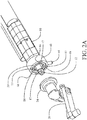
- FIGs. 2A and 2B An enhanced second embodiment is shown in FIGs. 2A and 2B .
- the magnets 17 may be held in a pattern on a face 39 of a rotatable sleeve 40 which concentrically surrounds the center drive interface 12.
- the mating magnetic elements 27 are positioned in a mating pattern in a non-magnetic mating face 25 on the second flange 24 on the end effector 20 such that with the rotatable sleeve 40 at a first rotational position the magnets 17 and mating magnetic elements 27 are aligned (as shown by phantom lines 31) for maximum magnetic attraction as seen in FIG.
- the magnets 17 and mating magnetic elements 27 are magnetically engaged.
- the magnetic elements 27 may be magnets or ferromagnetic coupons as previously described. If the magnetic elements 27 are optionally magnets, then the face 39 would be fabricated from non-magnetic material. As in the first embodiment, contact of the face 39 and mating face 25 on flange 24 mutually engages the center drive interface 12 and drive connection 22.
- the magnetic attraction is minimal and little or no force is required for the robotic manipulator 37 to separate the end effector and drive motor assembly.
- a paddle 42 may extend from the tool holder 34 and lateral motion of the drive motor assembly 10 along a lateral axis 45 perpendicular to the connection axis 38 by the robotic manipulator engages a lever 44 extending from the rotatable sleeve 40 to rotate the sleeve 40.
- Engagement of the paddle 42 by the lever 44 in a first direction along the lateral axis 45 induces rotation of the rotatable sleeve 40 for alignment of the magnets 17 and mating magnets 27 for activating magnetic engagement.
- engagement of the paddle 42 in a second direction along the lateral axis 45 induces rotation of the rotatable sleeve 40 to misalign the pattern of magnets 17 and magnetic elements 27 to deactivate the magnetic engagement.
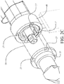
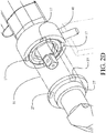
- the second embodiment may alternatively employ magnetically attractive metal inserts 46 as seen in FIG. 2A , 2C and 2D which are fixed in the flange 14 and align with the magnets 17 in the first rotational position of the rotatable sleeve 40.
- the metal inserts 46 When aligned, the metal inserts 46 will have an induced magnetic field from the magnets 17. When not aligned with the rotatable sleeve 40 in the second rotational position, the metal inserts 46 will not have any magnetic field.
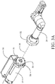
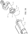
- FIGs. 3A - 3C demonstrate an alternative embodiment in which flange 50 on the drive motor assembly 10 and mating flange 52 on the end effector 20 are modified elliptical shapes.
- Antirotation shoulder 54 extending from the flange 50 is a concentric modified elliptical shape which is received in relief 56 in mating flange 52 (seen in FIG. 3B ). Shaping of the shoulder 54 and relief 56 prevent rotation when engaged.
- Flange 50 supports a plurality of magnets 58 which are placed in alignment for magnetic engagement with mating magnetic elements 60 supported by the mating flange 52 when the flange 50 and mating flange 52 are appropriately aligned for engagement of the antirotation shoulder 54 and relief 56.
- Engagement and disengagement of the drive motor assembly 10 and end effector 20 may be accomplished as previously described with respect to the first embodiment with use of a tool holder 34 for the end effector 20 using the robotic manipulator 37 to engage or withdraw the drive motor assembly 10 along connection axis 38 for engagement/disengagement of the magnets 58 and mating magnetic elements 60.
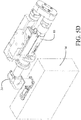
- Magnetic interengagement of the end effector 20 and drive motor assembly 10 may also be accomplished in a three point connection as shown for the embodiment in FIGs. 4A-4C .
- This configuration allows implementation of a torque transducer 62 in a floating drive train engaged by a gear 64 as seen in FIG. 4A .
- the torque transducer 62 is concentric with the center drive interface 12 extending through the center aperture 18 in flange 14 as in the first embodiment.
- Interengagement between the end effector 20 and the drive motor assembly 10 is accomplished at a first point between the center drive interface 12 and drive connection 22 accessed through mating aperture 28 in flange 24.
- the second point of engagement is 10between gear 64 extending from the torque transducer 62 and mating teeth 64 in the end effector 20.
- the third point of engagement is provided with a plurality of antirotation protrusions 66 extending from the periphery of flange 14 to be received in a plurality of mating slots 68 in the periphery 25 of mating flange 24-. While multiple protrusions 66 and slots 68 are shown in the exemplary embodiment a single protrusion and mating slot or alternatively cylindrical pins to mating holes or slots may be employed.
- Contact of the flange 14 and mating flange 24 mutually engages the center drive interface12 and drive connection 22 and engages the protrusions 66 in slots 68 as the antirotation mechanism.
- the magnetic element 16 and mating magnetic element 26 separably engage flange 14 and mating flange 24 to secure the end effector 20 to the drive motor assembly 10 with magnetic engagement as seen in FIG. 4C .
- FIGs 5A-5D A fifth embodiment is shown in FIGs 5A-5D which improves resistance to moments exerted between the end effector 20 and the drive motor assembly 10.
- a coupling component a first flange 14 as in the first embodiment, extends from the drive motor assembly 10 concentric with a center drive interface comparable a to the center drive interface 12 of FIG 1A but not visible due to the length of the coupling component as will be described subsequently.
- the first flange 14 of the coupling component supports a magnetic element which consists of a plurality of magnets 16.
- An aperture 18 in the first flange 14 has an inner cylindrical portion 70 and an outer cylindrical portion 72 of greater diameter providing a shoulder relief. As seen in FIG.
- an end effector 20 has a drive connection 22 adapted to removably receive the center drive interface 12.
- a mating coupling component, a second flange 24 for the fifth embodiment, extends from the end effector tool 20 with a protrusion 74 concentric with the drive connection 22.
- the protrusion 74 has a first outer cylindrical portion 76 and a second inner cylindrical portion 78 of greater diameter to provide a shoulder.
- the protrusion 74 is separably received within the aperture 18 and a contact wall 80 of the cylindrical inner portion 70 receives a mating contact wall 82 of the first outer cylindrical portion 76 of the protrusion while the shoulder created by the second inner cylindrical portion 78 is received within the should relief provided by the outer cylindrical portion 72 of the aperture.
- the second flange 24 supports a mating magnetic element 26 which may be a feromagnetic metal face of the flange.
- the magnetic element 16 and mating magnetic element 26 separably engage by mutual magnetic attraction to connect the end effector tool 20 to the drive motor assembly 10.
- a mating aperture 28 in the protrusion 74 allows engagement of the center drive interface 12 and drive connection 22 contact of the flange 14 and mating second flange 24 mutually engages the center drive interface 12 and drive connection 22. Close engagement of the protrusion 74 within the aperture 18 resists lateral moments which may be incurred between the drive motor assembly 10 and end effector 20 during use.
- first outer cylindrical portion 76 and second inner cylindrical portion 78 o fhte protrusion 74 are chamfered to assist in alignment for engagement within the inner cylindrical portion 70 and outer cylindrical portion 72 of the aperture 18 in the drive motor assembly.
- an antirotation mechanism for the exemplary fifth embodiment is provided by a first portion comprising two cylindrical pins 84 extending from the second flange 24 while the second portion comprises two bores 86 in the first flange 14.
- the pins 84 are engaged in the bores 86 preventing relative rotation between the end effector 20 and the drive motor assembly 10.
- pins 84 are diametrically opposed on the second flange 24 and the bores 86 are diametrically opposed on the first flange 14 at a common radius with the pins. While a pair of pins and bores is shown for the exemplary embodiment, a single pin and bore or three or more pins and bores may be employed.
- the robotic manipulator 37 may position and operate the end effector 20 for manufacturing operations.
- a tool holder 34 may be employed to hold the end effector 20 for pickup by or disengagement from the drive motor assembly 10.
- the tool holder 34 incorporates a relief 36 sized to closely receive the profile of the end effector 20 as seen in FIG. 5D .
- the drive motor assembly 10 may then be withdrawn by robotic manipulator 37 along a connection axis 38 through the center drive interface 12 to break the magnetic engagement between the magnetic element 16 and mating magnetic element 26 thereby freeing the end effector 20 from the drive motor assembly as as previously described with respect to FIG. 1E .
- a method for coupling a robotic end effector employing the embodiments disclosed is accomplished as shown in FIG. 6 with reference to exemplary embodiments of FIGs. 5A-5D .
- a robotic manipulator having a drive motor assembly 10 including a center drive interface 12 is aligned with a drive connection on an end effector 20, step 602.
- a coupling component such as flange 14, having a aperture 18 and a magnet element, such as a plurality of magnets 16, and extending from the drive motor assembly 10 concentric with the center drive interface 12 is engaged with a mating coupling component, such as second flange 24, having a protrusion 74 and a mating magnetic element 26 and extending from the end effector 20 concentric with the drive connection 22, by inserting the protrusion 74 into the aperture 18, step 603 and then engaging the magnetic element and mating magnetic element, step 604.
- the magnetic element and mating magnetic element are separably engaged by mutual magnetic attraction.
- the end effector tool may be secured in a tool holder 34, step 606, and the robotic manipulator 37 may withdraw the drive motor assembly 10 to separate the magnetic element and mating magnetic element to break the mutual magnetic attraction and remove the end effector 20 from the drive motor assembly 10, step 608.
- a contact wall in the aperture and a mating contact wall on the protrusion provide resistance to any moments between the end effector and drive motor assembly, step 610, thereby reducing the required magnetic force necessary to effectively engage the end effector tool to the drive motor assembly.
- Embodiments of the disclosure may be employed in the context of an aircraft manufacturing and service method 700 (method 700) as shown in FIG. 7 and an aircraft 800 as shown in FIG. 8 .
- the exemplary method 700 may include specification and design 704 of the aircraft 800 and material procurement 706.
- component and subassembly manufacturing 708 and system integration 710 of the aircraft 800 takes place.
- the aircraft 800 may go through certification and delivery 712 in order to be placed in service 714.
- routine maintenance and service 716 which may also include modification, reconfiguration, refurbishment, and so on).
- a system integrator may include without limitation any number of aircraft manufacturers and major-system subcontractors; a third party may include without limitation any number of venders, subcontractors, and suppliers; and an operator may be without limitation an airline, leasing company, military entity, service organization, and the like.
- the aircraft 800 produced by the exemplary method 700 may include an airframe 818 with a plurality of systems 820 and an interior 822.
- high-level systems 820 include one or more of a propulsion system 824, an electrical system 826, a hydraulic system 828, an environmental system 830, and flight control system 832. Any number of other systems may also be included.
- an aerospace example is shown, the embodiments of the disclosure may be applied to other industries.
- the embodiemnts disclosed herein may be used on steps or elements 708, 710, 714, 716, 818 and 822. of the method and aircraft as disclosed in FIGs. 7 and 8
- Apparatus and methods embodied herein and previously described may be employed during any one or more of the stages of the production and service method 700.
- components or subassemblies corresponding to production process 708 may be fabricated or manufactured in a manner similar to components or subassemblies produced while the aircraft 800 is in service.
- one or more apparatus embodiments as described herein, method embodiments described herein, or a combination thereof may be utilized during the production stages 708 and 710, for example, by substantially expediting assembly of or reducing the cost of an aircraft 800.
- apparatus embodiments, method embodiments, or a combination thereof may be utilized while the aircraft 800 is in service, for example and without limitation, to maintenance and service 716.
- the robotic end effector quick change coupling apparatus as defined in paragraph A1 further comprising a tool holder adapted to removably receive and secure said end effector tool whereby motion of the robotic manipulator in the at least one axis separates the coupling component and the mating coupling component.
- the robotic end effector quick change coupling apparatus as defined in paragraph A3 wherein the coupling component comprises a first flange incorporating the aperture concentric with the center drive interface and the mating coupling component comprises a second flange having an aperture concentric with the drive connection whereby contact of the first flange and second flange mutually engages the center drive interface and drive connection.
- the robotic end effector quick change coupling apparatus defined in paragraph A4 wherein the contact wall of the aperture in the coupling component has a first portion of a first diameter and a second portion of second diameter and the mating contact wall on the protrusion of the mating coupling component has a mating first portion to be received within the first diameter and a mating second portion to be received within the second diameter.
- the robotic end effector quick change coupling apparatus as defined in paragraph A3 wherein the magnetic element comprises a magnet and the mating magnetic element comprises a magnetically attractive metal.
- the robotic end effector quick change coupling apparatus as defined in paragraph A3 wherein the magnetic element comprises a plurality of magnets circumferentially spaced in a pattern on the flange and the mating magnetic element comprises a feromagnetic mating flange.
- the robotic end effector quick change coupling apparatus as defined in paragraph A1 further comprising an antirotation mechanism having a first portion associated with the coupling component and a second portion associated with the mating coupling component.
- the robotic end effector quick change coupling apparatus as defined in paragraph A10 wherein the coupling component comprises a first flange incorporating the aperture concentric with the center drive interface, said aperture having a shoulder and the mating coupling component comprises a second flange having a second aperture concentric with the drive connection, said second aperture having a relief, whereby contact of the first flange and second flange mutually engages the center drive interface and drive connection and engages the shoulder in the relief.
- the robotic end effector quick change coupling apparatus as defined in paragraph A11 wherein the first portion comprises at least one pin extending from the first flange and the second portion comprises at least one bore in the mating flange receiving said at least one pin.
- the robotic end effector quick change coupling apparatus as defined in paragraph A12 wherein the at least one pin comprises a pair of pins diametrically opposed on said first flange and the at least one bore comprises a pair of bores diametrically opposed on said second flange at an equal radius with the pair of pins.
- the robotic manipulator has a drive motor assembly including a center drive interface with a drive connection and the coupling component comprises a collar rotatably attached to the drive motor assembly and the magnetic element comprises a plurality of magnets circumferentially spaced on a face of the collar, the mating coupling component comprises a mating flange having a mating face and an aperture concentric with the drive connection and the mating magnetic element comprises a plurality of magnetically attractive metal coupons circumferentially spaced on the mating face at a common spacing with the plurality of magnets, the method further comprising:
- the robotic end effector quick change coupling apparatus as defined in paragraph C1 further comprising a tool holder adapted to removably receive and secure said end effector tool whereby motion of the robotic manipulator in the at least one axis separates the coupling component and the mating coupling component.
- the robotic end effector quick change coupling apparatus as defined in paragraph C3 wherein the coupling component comprises a first flange having a center aperture concentric with the center drive interface and the mating coupling component comprises a second flange having an aperture concentric with the drive connection whereby contact of the first flange and second flange mutually engages the center drive interface and drive connection.
- the robotic end effector quick change coupling apparatus as defined in paragraph C3 wherein the magnetic element comprises a magnet and the mating magnetic element comprises a magnetically attractive metal.
- the robotic end effector quick change coupling apparatus as defined in paragraph C3 wherein the magnetic element comprises a plurality of magnets circumferentially spaced in a pattern on the flange and the mating magnetic element comprises a plurality of ferromagnetic coupons circumferentially spaced on the mating flange in a mating pattern with the plurality of magnets.
- the robotic end effector quick change coupling apparatus as defined in paragraph C3 wherein the magnetic element comprises a first plurality of magnets circumferentially spaced on the flange and having a first polarity and the mating magnetic element comprises a second plurality of magnets circumferentially spaced on the mating flange at a common spacing with the first plurality of magnets and having a polarity opposite to the first polarity.
- the robotic end effector quick change coupling apparatus as defined in paragraph C9 wherein the drive motor assembly is operably connected to a robotic manipulator having controllable motion in at least two axes and further comprising:
- the robotic end effector quick change coupling apparatus as defined in paragraph C1 further comprising an antirotation mechanism having a first portion associated with the coupling component and a second portion associated with the mating coupling component.
- the robotic end effector quick change coupling apparatus as defined in paragraph 3 wherein the coupling component comprises a first flange having a center aperture concentric with the center drive interface, said aperture having a shoulder and the mating coupling component comprises a second flange having a second aperture concentric with the drive connection, said second aperture having a relief, whereby contact of the first flange and second flange mutually engages the center drive interface and drive connection and engages the shoulder in the relief.
- the robotic end effector quick change coupling apparatus as defined in paragraph C11 wherein the coupling component comprises a first flange having a center aperture concentric with the center drive interface, said flange having at least one slot and the mating coupling component comprises a second flange having a second aperture concentric with the drive connection, said second flange having at least one protrusion, whereby contact of the first flange and second flange mutually engages the center drive interface and drive connection and engages the at least one protrusion in the at least one slot.
- the robotic end effector quick change coupling apparatus as defined in paragraph C14 wherein the at least one slot comprises a plurality of slots on a periphery of the first flange and the at least one protrusion comprises a plurality of protrusions on a periphery of the second flange.
- the robotic end effector quick change coupling apparatus as defined in paragraph 3 wherein the center drive interface includes a floating drive train having a torque transducer.
- the robotic manipulator has a drive motor assembly including a center drive interface with a drive connection and the coupling component comprises a collar rotatably attached to the drive motor assembly and the magnetic element comprises a plurality of magnets circumferentially spaced on a face of the collar, the mating coupling component comprises a mating flange having a mating face and an aperture concentric with the drive connection and the mating magnetic element comprises a plurality of magnetically attractive metal coupons circumferentially spaced on the mating face at a common spacing with the plurality of magnets, the method further comprising:
Landscapes
- Engineering & Computer Science (AREA)
- Robotics (AREA)
- Mechanical Engineering (AREA)
- Manipulator (AREA)
Applications Claiming Priority (2)
| Application Number | Priority Date | Filing Date | Title |
|---|---|---|---|
| US15/017,814 US10335958B2 (en) | 2016-02-08 | 2016-02-08 | Robotic end effector quick change mechanism with switchable magnetic coupler |
| US15/068,328 US10414055B2 (en) | 2016-02-08 | 2016-03-11 | Robotic end effector quick change mechanism with switchable magnetic coupler with moment support |
Publications (3)
| Publication Number | Publication Date |
|---|---|
| EP3202541A2 true EP3202541A2 (fr) | 2017-08-09 |
| EP3202541A3 EP3202541A3 (fr) | 2017-10-25 |
| EP3202541B1 EP3202541B1 (fr) | 2019-11-20 |
Family
ID=57944237
Family Applications (1)
| Application Number | Title | Priority Date | Filing Date |
|---|---|---|---|
| EP16206468.7A Active EP3202541B1 (fr) | 2016-02-08 | 2016-12-22 | Mécanisme de changement rapide d'organe robotique effecteur avec coupleur magnétique commutable à support de moment |
Country Status (5)
| Country | Link |
|---|---|
| US (1) | US10414055B2 (fr) |
| EP (1) | EP3202541B1 (fr) |
| JP (1) | JP7005146B2 (fr) |
| ES (1) | ES2768781T3 (fr) |
| PT (1) | PT3202541T (fr) |
Cited By (4)
| Publication number | Priority date | Publication date | Assignee | Title |
|---|---|---|---|---|
| WO2020018468A1 (fr) | 2018-07-16 | 2020-01-23 | Xyz Robotics Inc. | Système robotisé permettant de prélever, trier et placer une pluralité d'objets aléatoires et nouveaux |
| EP3763492A1 (fr) * | 2019-07-12 | 2021-01-13 | pi4_robotics GmbH | Système et procédé de changement d'un organe terminal sur un robot |
| EP3743248A4 (fr) * | 2018-01-22 | 2021-11-10 | Oceaneering International, Inc. | Interface adaptative d'outillage |
| CN115431293A (zh) * | 2022-09-29 | 2022-12-06 | 安徽纳赫智能科技有限公司 | 一种拆垛端拾器快换装置 |
Families Citing this family (28)
| Publication number | Priority date | Publication date | Assignee | Title |
|---|---|---|---|---|
| US10335958B2 (en) * | 2016-02-08 | 2019-07-02 | The Boeing Company | Robotic end effector quick change mechanism with switchable magnetic coupler |
| US11167434B2 (en) * | 2016-08-30 | 2021-11-09 | HighRes Biosolutions, Inc. | Robotic processing system |
| USD839332S1 (en) * | 2017-08-23 | 2019-01-29 | Brent Andrew BAILEY | End effector |
| USD827006S1 (en) * | 2017-09-06 | 2018-08-28 | Hiwin Technologies Corp. | Robotic arm |
| USD827005S1 (en) * | 2017-09-06 | 2018-08-28 | Hwin Technologies Corp. | Robotic arm |
| US11528913B1 (en) * | 2018-02-13 | 2022-12-20 | Kent Deemter | Automated food preparation apparatus |
| USD883351S1 (en) * | 2018-05-10 | 2020-05-05 | Robotiq Inc. | Robotic end effector |
| US12103180B2 (en) | 2018-05-13 | 2024-10-01 | Robotiq Inc. | Robotic gripper |
| USD898090S1 (en) * | 2018-05-18 | 2020-10-06 | Universal Robots A/S | Toothed connection flange for a robot joint |
| USD895705S1 (en) * | 2018-05-18 | 2020-09-08 | Universal Robots A/S | Robot joint having an input flange, an output flange, and a top lid |
| CA3107825C (fr) * | 2018-07-27 | 2023-06-13 | Berkshire Grey, Inc. | Systemes et procedes pour echanger efficacement des outils d'effecteur d'extremite |
| KR102155799B1 (ko) * | 2018-08-21 | 2020-09-14 | 두림야스카와(주) | 도장 로봇용 티칭 툴 |
| WO2020241914A1 (fr) * | 2019-05-28 | 2020-12-03 | 엘지전자 주식회사 | Maître et esclave d'un système de changement d'outil robotisé |
| KR102769054B1 (ko) * | 2019-09-17 | 2025-02-19 | 엘지전자 주식회사 | 툴 커플러, 툴 체인저 및 이를 포함하는 툴체인지 시스템 |
| WO2021081388A1 (fr) * | 2019-10-23 | 2021-04-29 | Xyz Robotics Inc. | Changeur d'outil terminal effecteur pour systèmes robotiques de préhension et de placement |
| CN113878600B (zh) * | 2020-07-02 | 2023-05-09 | 台达电子工业股份有限公司 | 可替换式夹爪模块以及抓取元件的替换方法 |
| US11440203B2 (en) * | 2020-09-04 | 2022-09-13 | Toyota Research Institute, Inc. | Robotic tool changers and methods of use |
| JP6883907B1 (ja) * | 2020-09-09 | 2021-06-09 | KiQ Robotics株式会社 | ロボットアームの把持装置及びこれを用いたロボットアーム |
| WO2023115207A1 (fr) * | 2021-12-20 | 2023-06-29 | Macdonald, Dettwiler And Associates Inc. | Système, procédé et dispositif d'interface robotique résistante à la poussière |
| USD1082878S1 (en) | 2022-01-14 | 2025-07-08 | Universal Robots A/S | Robot joint |
| USD1099187S1 (en) | 2022-01-14 | 2025-10-21 | Universal Robots A/S | Robot joint |
| WO2023200451A1 (fr) * | 2022-04-14 | 2023-10-19 | Xyz Robotics Inc. | Changeur d'outil d'effecteur pour systèmes robotiques |
| CN117283592A (zh) * | 2022-06-17 | 2023-12-26 | 星猿哲科技(上海)有限公司 | 用于机器人系统的末端执行器工具更换装置 |
| US20240066709A1 (en) * | 2022-08-23 | 2024-02-29 | The Boeing Company | Normalizing Nosepiece Assembly for an End Effector |
| JP7694539B2 (ja) * | 2022-11-15 | 2025-06-18 | トヨタ自動車株式会社 | 車載カメラの光軸位置調整方法及び光軸位置調整具 |
| KR102844383B1 (ko) * | 2023-06-29 | 2025-08-08 | 주식회사 레인보우로보틱스 | 마그네틱 툴 체인저 |
| CN116834050A (zh) * | 2023-08-08 | 2023-10-03 | 北京理工大学 | 一种自动更换螺丝刀批头系统 |
| CN119589695B (zh) * | 2024-12-20 | 2025-07-18 | 江苏宝镭激光科技有限公司 | 一种具备滚头快换机构的滚边加工机械手 |
Family Cites Families (25)
| Publication number | Priority date | Publication date | Assignee | Title |
|---|---|---|---|---|
| US1200143A (en) * | 1916-03-04 | 1916-10-03 | Alfred V Schrade | Adjustable insulated coupling for motors and dynamos. |
| US2300778A (en) * | 1939-11-22 | 1942-11-03 | Cinaudagraph Corp | Sound reproducer drive |
| US2481360A (en) * | 1948-07-21 | 1949-09-06 | Gen Electric | Intermittent motion magnetic drive |
| SE453168B (sv) | 1982-04-19 | 1988-01-18 | Lennart Palmer | Anordning for att utbytbart anordna verktyg pa en industrirobot |
| JPS6034282A (ja) * | 1983-08-08 | 1985-02-21 | 株式会社日立製作所 | 着脱自在なマニプレ−タ |
| DE3340912A1 (de) * | 1983-11-11 | 1985-05-23 | Siemens AG, 1000 Berlin und 8000 München | Flansch zum automatisierten wechsel der greifer von industrie-robotern |
| EP0150232A1 (fr) * | 1984-01-26 | 1985-08-07 | Wilhelm Karmann GmbH | Procédé de fonctionnement pour un robot industriel et robot industriel employé dans ce procédé |
| SU1556896A1 (ru) | 1987-02-17 | 1990-04-15 | Предприятие П/Я Ю-9469 | Устройство дл стыковки сменного схвата с рукой манипул тора |
| JPS6440287A (en) * | 1987-08-07 | 1989-02-10 | Canon Kk | Finger fitting system |
| US4860864A (en) * | 1987-11-16 | 1989-08-29 | General Motors Corporation | Clutch for robot or like |
| US4897014A (en) * | 1988-09-06 | 1990-01-30 | Harbor Branch Oceanographic Institution, Inc. | Device for interchange of tools |
| JPH05177569A (ja) * | 1991-12-24 | 1993-07-20 | Nitta Ind Corp | 自動工具交換用カップラー |
| US5261758A (en) * | 1992-07-27 | 1993-11-16 | The United States Of America As Represented By The Administrator Of The National Aeronautics And Space Administration | Split spline screw |
| JP3609919B2 (ja) * | 1997-06-19 | 2005-01-12 | 京セラミタ株式会社 | 画像形成装置用の軸継手 |
| DE20018124U1 (de) | 2000-10-23 | 2002-03-07 | Stäubli Vertriebs-GmbH, 95448 Bayreuth | Werkzeugwechselsystem und Kupplungssystem |
| EP1543915B1 (fr) * | 2003-12-16 | 2008-03-26 | Trumpf Werkzeugmaschinen GmbH + Co. KG | Dispositif de protection contre les collisions d'une tête d'usinage au laser |
| KR101412130B1 (ko) * | 2008-03-14 | 2014-06-27 | 삼성전자주식회사 | 컴플라이언트 조인트 |
| AT508792B1 (de) * | 2009-09-10 | 2011-08-15 | Fronius Int Gmbh | Kollisionsschutzeinrichtung |
| US8936290B1 (en) | 2012-08-29 | 2015-01-20 | Sandia Corporation | Robotic hand with modular extensions |
| DE102013111938B3 (de) | 2013-10-30 | 2014-11-27 | Alexander Binzel Schweisstechnik Gmbh & Co. Kg | Magnetische Schweißwerkzeugkupplung, Schweißwerkzeug sowie Schweißvorrichtung |
| US10661449B2 (en) * | 2014-08-20 | 2020-05-26 | Ati Industrial Automation, Inc. | Safe robotic tool changer |
| KR101949057B1 (ko) * | 2014-08-20 | 2019-02-15 | 에이티아이 인더스트리얼 오토메이션, 인크. | 공구 스탠드 디커플링 전원을 갖는 로봇식 공구 교환기 |
| MX372870B (es) | 2014-08-26 | 2020-07-08 | Vineland Res And Innovation Centre | Cosechadora de hongos |
| CN105364943B (zh) * | 2014-08-29 | 2020-04-17 | 鸿富锦精密工业(深圳)有限公司 | 固接装置及使用该固接装置的机械臂与机器人 |
| US10688669B2 (en) | 2015-10-30 | 2020-06-23 | Fetch Robotics, Inc. | Wireless quick change end effector system for use with a robot |
-
2016
- 2016-03-11 US US15/068,328 patent/US10414055B2/en active Active
- 2016-12-22 EP EP16206468.7A patent/EP3202541B1/fr active Active
- 2016-12-22 ES ES16206468T patent/ES2768781T3/es active Active
- 2016-12-22 PT PT162064687T patent/PT3202541T/pt unknown
-
2017
- 2017-01-25 JP JP2017011280A patent/JP7005146B2/ja active Active
Non-Patent Citations (1)
| Title |
|---|
| None |
Cited By (8)
| Publication number | Priority date | Publication date | Assignee | Title |
|---|---|---|---|---|
| EP3743248A4 (fr) * | 2018-01-22 | 2021-11-10 | Oceaneering International, Inc. | Interface adaptative d'outillage |
| WO2020018468A1 (fr) | 2018-07-16 | 2020-01-23 | Xyz Robotics Inc. | Système robotisé permettant de prélever, trier et placer une pluralité d'objets aléatoires et nouveaux |
| CN112166013A (zh) * | 2018-07-16 | 2021-01-01 | 星猿哲机器人全球有限公司 | 用于挑选、分类及放置复数个随机及新物品的机器人系统 |
| EP3823799A4 (fr) * | 2018-07-16 | 2022-05-04 | XYZ Robotics Inc. | Système robotisé permettant de prélever, trier et placer une pluralité d'objets aléatoires et nouveaux |
| CN112166013B (zh) * | 2018-07-16 | 2023-09-26 | 星猿哲机器人全球有限公司 | 用于挑选、分类及放置复数个随机及新物品的机器人系统 |
| EP3763492A1 (fr) * | 2019-07-12 | 2021-01-13 | pi4_robotics GmbH | Système et procédé de changement d'un organe terminal sur un robot |
| CN115431293A (zh) * | 2022-09-29 | 2022-12-06 | 安徽纳赫智能科技有限公司 | 一种拆垛端拾器快换装置 |
| CN115431293B (zh) * | 2022-09-29 | 2024-05-31 | 安徽纳赫智能科技有限公司 | 一种拆垛端拾器快换装置 |
Also Published As
| Publication number | Publication date |
|---|---|
| US20170225341A1 (en) | 2017-08-10 |
| US10414055B2 (en) | 2019-09-17 |
| ES2768781T3 (es) | 2020-06-23 |
| EP3202541A3 (fr) | 2017-10-25 |
| JP7005146B2 (ja) | 2022-01-21 |
| PT3202541T (pt) | 2020-03-02 |
| JP2017170606A (ja) | 2017-09-28 |
| EP3202541B1 (fr) | 2019-11-20 |
Similar Documents
| Publication | Publication Date | Title |
|---|---|---|
| EP3202541B1 (fr) | Mécanisme de changement rapide d'organe robotique effecteur avec coupleur magnétique commutable à support de moment | |
| US10335958B2 (en) | Robotic end effector quick change mechanism with switchable magnetic coupler | |
| US12202632B2 (en) | Capture and docking mechanisms for spacecrafts | |
| US10252383B2 (en) | Bolting tool and bolt mounting jig | |
| US9849586B2 (en) | Robotic manipulator | |
| US10576644B2 (en) | Articulated mechanism with internal brake assembly | |
| US12151366B2 (en) | Separable robotic interface | |
| US20150343582A1 (en) | Tool gripping mechanism | |
| US10933475B2 (en) | Tool clamping system | |
| US20170072567A1 (en) | Enhanced Robotic Teaching Tool | |
| KR20200035207A (ko) | 스웨이지 공구들을 위한 오프셋 칼라 전달 | |
| US5326186A (en) | Robot friendly probe and socket assembly | |
| EP4074994B1 (fr) | Outillage et procédés de synchronisation de doubles bagues excentriques d'une chape | |
| JP2015186326A (ja) | モーター、ロボット、モーターの組み立て方法 | |
| CN112994277B (zh) | 具有海尔贝克阵列的多自由度电磁机器 | |
| CN104128926B (zh) | 使用现有零件特征部的零件传递系统和使用该系统的方法 | |
| US11148188B2 (en) | Tool and associated method for installing a blind fastener | |
| CN107932057B (zh) | 一种航空发动机动力涡轮转子扭矩测量系统装配方法 | |
| US11901776B2 (en) | Adapter for motor replacement and motor replacement method | |
| JP6812127B2 (ja) | 航空機胴体接合部に開口部を形成するための反作用ツール及び方法 | |
| US20220136627A1 (en) | Compression fitting with visual torque indicator | |
| EP4616999A2 (fr) | Outils et procédés de fixation | |
| US20060049629A1 (en) | Coupling unit with magnetic latching | |
| US9751166B2 (en) | Apparatus and methods for manipulating a fastener | |
| JP7130539B2 (ja) | 位置決めピン |
Legal Events
| Date | Code | Title | Description |
|---|---|---|---|
| PUAI | Public reference made under article 153(3) epc to a published international application that has entered the european phase |
Free format text: ORIGINAL CODE: 0009012 |
|
| STAA | Information on the status of an ep patent application or granted ep patent |
Free format text: STATUS: REQUEST FOR EXAMINATION WAS MADE |
|
| 17P | Request for examination filed |
Effective date: 20161222 |
|
| AK | Designated contracting states |
Kind code of ref document: A2 Designated state(s): AL AT BE BG CH CY CZ DE DK EE ES FI FR GB GR HR HU IE IS IT LI LT LU LV MC MK MT NL NO PL PT RO RS SE SI SK SM TR |
|
| AX | Request for extension of the european patent |
Extension state: BA ME |
|
| PUAL | Search report despatched |
Free format text: ORIGINAL CODE: 0009013 |
|
| AK | Designated contracting states |
Kind code of ref document: A3 Designated state(s): AL AT BE BG CH CY CZ DE DK EE ES FI FR GB GR HR HU IE IS IT LI LT LU LV MC MK MT NL NO PL PT RO RS SE SI SK SM TR |
|
| AX | Request for extension of the european patent |
Extension state: BA ME |
|
| RIC1 | Information provided on ipc code assigned before grant |
Ipc: B25J 15/04 20060101AFI20170921BHEP |
|
| RBV | Designated contracting states (corrected) |
Designated state(s): AL AT BE BG CH CY CZ DE DK EE ES FI FR GB GR HR HU IE IS IT LI LT LU LV MC MK MT NL NO PL PT RO RS SE SI SK SM TR |
|
| GRAP | Despatch of communication of intention to grant a patent |
Free format text: ORIGINAL CODE: EPIDOSNIGR1 |
|
| STAA | Information on the status of an ep patent application or granted ep patent |
Free format text: STATUS: GRANT OF PATENT IS INTENDED |
|
| INTG | Intention to grant announced |
Effective date: 20181114 |
|
| GRAJ | Information related to disapproval of communication of intention to grant by the applicant or resumption of examination proceedings by the epo deleted |
Free format text: ORIGINAL CODE: EPIDOSDIGR1 |
|
| STAA | Information on the status of an ep patent application or granted ep patent |
Free format text: STATUS: REQUEST FOR EXAMINATION WAS MADE |
|
| INTC | Intention to grant announced (deleted) | ||
| GRAP | Despatch of communication of intention to grant a patent |
Free format text: ORIGINAL CODE: EPIDOSNIGR1 |
|
| STAA | Information on the status of an ep patent application or granted ep patent |
Free format text: STATUS: GRANT OF PATENT IS INTENDED |
|
| INTG | Intention to grant announced |
Effective date: 20190528 |
|
| GRAS | Grant fee paid |
Free format text: ORIGINAL CODE: EPIDOSNIGR3 |
|
| GRAA | (expected) grant |
Free format text: ORIGINAL CODE: 0009210 |
|
| STAA | Information on the status of an ep patent application or granted ep patent |
Free format text: STATUS: THE PATENT HAS BEEN GRANTED |
|
| AK | Designated contracting states |
Kind code of ref document: B1 Designated state(s): AL AT BE BG CH CY CZ DE DK EE ES FI FR GB GR HR HU IE IS IT LI LT LU LV MC MK MT NL NO PL PT RO RS SE SI SK SM TR |
|
| REG | Reference to a national code |
Ref country code: GB Ref legal event code: FG4D |
|
| REG | Reference to a national code |
Ref country code: CH Ref legal event code: EP |
|
| REG | Reference to a national code |
Ref country code: IE Ref legal event code: FG4D |
|
| REG | Reference to a national code |
Ref country code: DE Ref legal event code: R096 Ref document number: 602016024608 Country of ref document: DE |
|
| REG | Reference to a national code |
Ref country code: AT Ref legal event code: REF Ref document number: 1203683 Country of ref document: AT Kind code of ref document: T Effective date: 20191215 |
|
| REG | Reference to a national code |
Ref country code: PT Ref legal event code: SC4A Ref document number: 3202541 Country of ref document: PT Date of ref document: 20200302 Kind code of ref document: T Free format text: AVAILABILITY OF NATIONAL TRANSLATION Effective date: 20200219 |
|
| REG | Reference to a national code |
Ref country code: SE Ref legal event code: TRGR |
|
| REG | Reference to a national code |
Ref country code: NL Ref legal event code: MP Effective date: 20191120 |
|
| REG | Reference to a national code |
Ref country code: LT Ref legal event code: MG4D |
|
| PG25 | Lapsed in a contracting state [announced via postgrant information from national office to epo] |
Ref country code: NL Free format text: LAPSE BECAUSE OF FAILURE TO SUBMIT A TRANSLATION OF THE DESCRIPTION OR TO PAY THE FEE WITHIN THE PRESCRIBED TIME-LIMIT Effective date: 20191120 Ref country code: BG Free format text: LAPSE BECAUSE OF FAILURE TO SUBMIT A TRANSLATION OF THE DESCRIPTION OR TO PAY THE FEE WITHIN THE PRESCRIBED TIME-LIMIT Effective date: 20200220 Ref country code: FI Free format text: LAPSE BECAUSE OF FAILURE TO SUBMIT A TRANSLATION OF THE DESCRIPTION OR TO PAY THE FEE WITHIN THE PRESCRIBED TIME-LIMIT Effective date: 20191120 Ref country code: NO Free format text: LAPSE BECAUSE OF FAILURE TO SUBMIT A TRANSLATION OF THE DESCRIPTION OR TO PAY THE FEE WITHIN THE PRESCRIBED TIME-LIMIT Effective date: 20200220 Ref country code: GR Free format text: LAPSE BECAUSE OF FAILURE TO SUBMIT A TRANSLATION OF THE DESCRIPTION OR TO PAY THE FEE WITHIN THE PRESCRIBED TIME-LIMIT Effective date: 20200221 Ref country code: LT Free format text: LAPSE BECAUSE OF FAILURE TO SUBMIT A TRANSLATION OF THE DESCRIPTION OR TO PAY THE FEE WITHIN THE PRESCRIBED TIME-LIMIT Effective date: 20191120 Ref country code: LV Free format text: LAPSE BECAUSE OF FAILURE TO SUBMIT A TRANSLATION OF THE DESCRIPTION OR TO PAY THE FEE WITHIN THE PRESCRIBED TIME-LIMIT Effective date: 20191120 |
|
| PG25 | Lapsed in a contracting state [announced via postgrant information from national office to epo] |
Ref country code: HR Free format text: LAPSE BECAUSE OF FAILURE TO SUBMIT A TRANSLATION OF THE DESCRIPTION OR TO PAY THE FEE WITHIN THE PRESCRIBED TIME-LIMIT Effective date: 20191120 Ref country code: RS Free format text: LAPSE BECAUSE OF FAILURE TO SUBMIT A TRANSLATION OF THE DESCRIPTION OR TO PAY THE FEE WITHIN THE PRESCRIBED TIME-LIMIT Effective date: 20191120 Ref country code: IS Free format text: LAPSE BECAUSE OF FAILURE TO SUBMIT A TRANSLATION OF THE DESCRIPTION OR TO PAY THE FEE WITHIN THE PRESCRIBED TIME-LIMIT Effective date: 20200320 |
|
| REG | Reference to a national code |
Ref country code: ES Ref legal event code: FG2A Ref document number: 2768781 Country of ref document: ES Kind code of ref document: T3 Effective date: 20200623 |
|
| PG25 | Lapsed in a contracting state [announced via postgrant information from national office to epo] |
Ref country code: AL Free format text: LAPSE BECAUSE OF FAILURE TO SUBMIT A TRANSLATION OF THE DESCRIPTION OR TO PAY THE FEE WITHIN THE PRESCRIBED TIME-LIMIT Effective date: 20191120 |
|
| PG25 | Lapsed in a contracting state [announced via postgrant information from national office to epo] |
Ref country code: RO Free format text: LAPSE BECAUSE OF FAILURE TO SUBMIT A TRANSLATION OF THE DESCRIPTION OR TO PAY THE FEE WITHIN THE PRESCRIBED TIME-LIMIT Effective date: 20191120 Ref country code: CZ Free format text: LAPSE BECAUSE OF FAILURE TO SUBMIT A TRANSLATION OF THE DESCRIPTION OR TO PAY THE FEE WITHIN THE PRESCRIBED TIME-LIMIT Effective date: 20191120 Ref country code: DK Free format text: LAPSE BECAUSE OF FAILURE TO SUBMIT A TRANSLATION OF THE DESCRIPTION OR TO PAY THE FEE WITHIN THE PRESCRIBED TIME-LIMIT Effective date: 20191120 Ref country code: EE Free format text: LAPSE BECAUSE OF FAILURE TO SUBMIT A TRANSLATION OF THE DESCRIPTION OR TO PAY THE FEE WITHIN THE PRESCRIBED TIME-LIMIT Effective date: 20191120 |
|
| REG | Reference to a national code |
Ref country code: CH Ref legal event code: PL |
|
| REG | Reference to a national code |
Ref country code: AT Ref legal event code: MK05 Ref document number: 1203683 Country of ref document: AT Kind code of ref document: T Effective date: 20191120 |
|
| REG | Reference to a national code |
Ref country code: DE Ref legal event code: R097 Ref document number: 602016024608 Country of ref document: DE |
|
| REG | Reference to a national code |
Ref country code: BE Ref legal event code: MM Effective date: 20191231 |
|
| PG25 | Lapsed in a contracting state [announced via postgrant information from national office to epo] |
Ref country code: SK Free format text: LAPSE BECAUSE OF FAILURE TO SUBMIT A TRANSLATION OF THE DESCRIPTION OR TO PAY THE FEE WITHIN THE PRESCRIBED TIME-LIMIT Effective date: 20191120 Ref country code: MC Free format text: LAPSE BECAUSE OF FAILURE TO SUBMIT A TRANSLATION OF THE DESCRIPTION OR TO PAY THE FEE WITHIN THE PRESCRIBED TIME-LIMIT Effective date: 20191120 Ref country code: SM Free format text: LAPSE BECAUSE OF FAILURE TO SUBMIT A TRANSLATION OF THE DESCRIPTION OR TO PAY THE FEE WITHIN THE PRESCRIBED TIME-LIMIT Effective date: 20191120 |
|
| PLBE | No opposition filed within time limit |
Free format text: ORIGINAL CODE: 0009261 |
|
| STAA | Information on the status of an ep patent application or granted ep patent |
Free format text: STATUS: NO OPPOSITION FILED WITHIN TIME LIMIT |
|
| 26N | No opposition filed |
Effective date: 20200821 |
|
| PG25 | Lapsed in a contracting state [announced via postgrant information from national office to epo] |
Ref country code: IE Free format text: LAPSE BECAUSE OF NON-PAYMENT OF DUE FEES Effective date: 20191222 Ref country code: LU Free format text: LAPSE BECAUSE OF NON-PAYMENT OF DUE FEES Effective date: 20191222 |
|
| PG25 | Lapsed in a contracting state [announced via postgrant information from national office to epo] |
Ref country code: SI Free format text: LAPSE BECAUSE OF FAILURE TO SUBMIT A TRANSLATION OF THE DESCRIPTION OR TO PAY THE FEE WITHIN THE PRESCRIBED TIME-LIMIT Effective date: 20191120 Ref country code: LI Free format text: LAPSE BECAUSE OF NON-PAYMENT OF DUE FEES Effective date: 20191231 Ref country code: BE Free format text: LAPSE BECAUSE OF NON-PAYMENT OF DUE FEES Effective date: 20191231 Ref country code: CH Free format text: LAPSE BECAUSE OF NON-PAYMENT OF DUE FEES Effective date: 20191231 Ref country code: PL Free format text: LAPSE BECAUSE OF FAILURE TO SUBMIT A TRANSLATION OF THE DESCRIPTION OR TO PAY THE FEE WITHIN THE PRESCRIBED TIME-LIMIT Effective date: 20191120 Ref country code: AT Free format text: LAPSE BECAUSE OF FAILURE TO SUBMIT A TRANSLATION OF THE DESCRIPTION OR TO PAY THE FEE WITHIN THE PRESCRIBED TIME-LIMIT Effective date: 20191120 |
|
| PG25 | Lapsed in a contracting state [announced via postgrant information from national office to epo] |
Ref country code: CY Free format text: LAPSE BECAUSE OF FAILURE TO SUBMIT A TRANSLATION OF THE DESCRIPTION OR TO PAY THE FEE WITHIN THE PRESCRIBED TIME-LIMIT Effective date: 20191120 |
|
| PG25 | Lapsed in a contracting state [announced via postgrant information from national office to epo] |
Ref country code: HU Free format text: LAPSE BECAUSE OF FAILURE TO SUBMIT A TRANSLATION OF THE DESCRIPTION OR TO PAY THE FEE WITHIN THE PRESCRIBED TIME-LIMIT; INVALID AB INITIO Effective date: 20161222 Ref country code: MT Free format text: LAPSE BECAUSE OF FAILURE TO SUBMIT A TRANSLATION OF THE DESCRIPTION OR TO PAY THE FEE WITHIN THE PRESCRIBED TIME-LIMIT Effective date: 20191120 |
|
| PG25 | Lapsed in a contracting state [announced via postgrant information from national office to epo] |
Ref country code: MK Free format text: LAPSE BECAUSE OF FAILURE TO SUBMIT A TRANSLATION OF THE DESCRIPTION OR TO PAY THE FEE WITHIN THE PRESCRIBED TIME-LIMIT Effective date: 20191120 |
|
| P01 | Opt-out of the competence of the unified patent court (upc) registered |
Effective date: 20230516 |
|
| PGFP | Annual fee paid to national office [announced via postgrant information from national office to epo] |
Ref country code: GB Payment date: 20251229 Year of fee payment: 10 |
|
| PGFP | Annual fee paid to national office [announced via postgrant information from national office to epo] |
Ref country code: PT Payment date: 20251209 Year of fee payment: 10 |
|
| PGFP | Annual fee paid to national office [announced via postgrant information from national office to epo] |
Ref country code: IT Payment date: 20251219 Year of fee payment: 10 |
|
| PGFP | Annual fee paid to national office [announced via postgrant information from national office to epo] |
Ref country code: FR Payment date: 20251226 Year of fee payment: 10 |
|
| PGFP | Annual fee paid to national office [announced via postgrant information from national office to epo] |
Ref country code: TR Payment date: 20251216 Year of fee payment: 10 |
|
| PGFP | Annual fee paid to national office [announced via postgrant information from national office to epo] |
Ref country code: SE Payment date: 20251227 Year of fee payment: 10 |
|
| PGFP | Annual fee paid to national office [announced via postgrant information from national office to epo] |
Ref country code: ES Payment date: 20260102 Year of fee payment: 10 |
|
| PGFP | Annual fee paid to national office [announced via postgrant information from national office to epo] |
Ref country code: DE Payment date: 20251229 Year of fee payment: 10 |