EP3202994A1 - Bajonettröhrenkuppleranordnung für nachgespanntes betonelement - Google Patents
Bajonettröhrenkuppleranordnung für nachgespanntes betonelement Download PDFInfo
- Publication number
- EP3202994A1 EP3202994A1 EP17151184.3A EP17151184A EP3202994A1 EP 3202994 A1 EP3202994 A1 EP 3202994A1 EP 17151184 A EP17151184 A EP 17151184A EP 3202994 A1 EP3202994 A1 EP 3202994A1
- Authority
- EP
- European Patent Office
- Prior art keywords
- duct
- duct coupler
- male
- coupler
- female
- Prior art date
- Legal status (The legal status is an assumption and is not a legal conclusion. Google has not performed a legal analysis and makes no representation as to the accuracy of the status listed.)
- Granted
Links
Images




Classifications
-
- F—MECHANICAL ENGINEERING; LIGHTING; HEATING; WEAPONS; BLASTING
- F16—ENGINEERING ELEMENTS AND UNITS; GENERAL MEASURES FOR PRODUCING AND MAINTAINING EFFECTIVE FUNCTIONING OF MACHINES OR INSTALLATIONS; THERMAL INSULATION IN GENERAL
- F16L—PIPES; JOINTS OR FITTINGS FOR PIPES; SUPPORTS FOR PIPES, CABLES OR PROTECTIVE TUBING; MEANS FOR THERMAL INSULATION IN GENERAL
- F16L37/00—Couplings of the quick-acting type
- F16L37/24—Couplings of the quick-acting type in which the connection is made by inserting one member axially into the other and rotating it to a limited extent, e.g. with bayonet-action
- F16L37/244—Couplings of the quick-acting type in which the connection is made by inserting one member axially into the other and rotating it to a limited extent, e.g. with bayonet-action the coupling being co-axial with the pipe
- F16L37/248—Bayonet-type couplings
-
- B—PERFORMING OPERATIONS; TRANSPORTING
- B28—WORKING CEMENT, CLAY, OR STONE
- B28B—SHAPING CLAY OR OTHER CERAMIC COMPOSITIONS; SHAPING SLAG; SHAPING MIXTURES CONTAINING CEMENTITIOUS MATERIAL, e.g. PLASTER
- B28B1/00—Producing shaped prefabricated articles from the material
- B28B1/30—Producing shaped prefabricated articles from the material by applying the material on to a core or other moulding surface to form a layer thereon
-
- E—FIXED CONSTRUCTIONS
- E04—BUILDING
- E04C—STRUCTURAL ELEMENTS; BUILDING MATERIALS
- E04C5/00—Reinforcing elements, e.g. for concrete; Auxiliary elements therefor
- E04C5/08—Members specially adapted to be used in prestressed constructions
- E04C5/10—Ducts
-
- F—MECHANICAL ENGINEERING; LIGHTING; HEATING; WEAPONS; BLASTING
- F16—ENGINEERING ELEMENTS AND UNITS; GENERAL MEASURES FOR PRODUCING AND MAINTAINING EFFECTIVE FUNCTIONING OF MACHINES OR INSTALLATIONS; THERMAL INSULATION IN GENERAL
- F16L—PIPES; JOINTS OR FITTINGS FOR PIPES; SUPPORTS FOR PIPES, CABLES OR PROTECTIVE TUBING; MEANS FOR THERMAL INSULATION IN GENERAL
- F16L13/00—Non-disconnectable pipe joints, e.g. soldered, adhesive, or caulked joints
- F16L13/10—Adhesive or cemented joints
- F16L13/11—Adhesive or cemented joints using materials which fill the space between parts of a joint before hardening
- F16L13/116—Adhesive or cemented joints using materials which fill the space between parts of a joint before hardening for socket pipes
-
- B—PERFORMING OPERATIONS; TRANSPORTING
- B21—MECHANICAL METAL-WORKING WITHOUT ESSENTIALLY REMOVING MATERIAL; PUNCHING METAL
- B21D—WORKING OR PROCESSING OF SHEET METAL OR METAL TUBES, RODS OR PROFILES WITHOUT ESSENTIALLY REMOVING MATERIAL; PUNCHING METAL
- B21D11/00—Bending not restricted to forms of material mentioned in only one of groups B21D5/00, B21D7/00, B21D9/00; Bending not provided for in groups B21D5/00 - B21D9/00; Twisting
- B21D11/10—Bending specially adapted to produce specific articles, e.g. leaf springs
- B21D11/12—Bending specially adapted to produce specific articles, e.g. leaf springs the articles being reinforcements for concrete
-
- F—MECHANICAL ENGINEERING; LIGHTING; HEATING; WEAPONS; BLASTING
- F16—ENGINEERING ELEMENTS AND UNITS; GENERAL MEASURES FOR PRODUCING AND MAINTAINING EFFECTIVE FUNCTIONING OF MACHINES OR INSTALLATIONS; THERMAL INSULATION IN GENERAL
- F16L—PIPES; JOINTS OR FITTINGS FOR PIPES; SUPPORTS FOR PIPES, CABLES OR PROTECTIVE TUBING; MEANS FOR THERMAL INSULATION IN GENERAL
- F16L13/00—Non-disconnectable pipe joints, e.g. soldered, adhesive, or caulked joints
-
- Y—GENERAL TAGGING OF NEW TECHNOLOGICAL DEVELOPMENTS; GENERAL TAGGING OF CROSS-SECTIONAL TECHNOLOGIES SPANNING OVER SEVERAL SECTIONS OF THE IPC; TECHNICAL SUBJECTS COVERED BY FORMER USPC CROSS-REFERENCE ART COLLECTIONS [XRACs] AND DIGESTS
- Y10—TECHNICAL SUBJECTS COVERED BY FORMER USPC
- Y10T—TECHNICAL SUBJECTS COVERED BY FORMER US CLASSIFICATION
- Y10T29/00—Metal working
- Y10T29/49—Method of mechanical manufacture
- Y10T29/49616—Structural member making
- Y10T29/49623—Static structure, e.g., a building component
- Y10T29/49632—Metal reinforcement member for nonmetallic, e.g., concrete, structural element
Definitions
- the present disclosure relates generally to a conduit coupling device.
- the present disclosure relates more specifically to a duct coupler assembly for providing a joint between adjacent sections of conduit.
- Structural concrete though capable of carrying very high compressive loads, is generally weak in carrying tensile loads on its own. Reinforced concrete ameliorates this deficiency by including an internal structure formed from materials capable of withstanding tensile forces within an otherwise solid concrete structure. Metal bars or cables are often used due to their high tensile strength and relative ease of manufacture.
- the reinforcement structure may be pre- or post- tensioned. Added structural tension maintains a compression loading on the concrete member, even when tensile stress would otherwise occur, such as in beam-loading.
- the reinforcing structure is tensioned after the concrete has set.
- a series of conduits formed from duct segrments are placed within the concrete form, each conduit positioned parallel to the desired tensile preloading.
- the conduits are threaded with the one or more tensile members, such as metal cables. After the concrete has set, the metal cables may then be placed under tension, and anchored to either end of the conduit, thus placing the concrete member under tensile loading.
- duct segments in the existing concrete member are traditionally be coupled to ducts placed in the form of the new concrete member.
- the present disclosure provides a duct coupler assembly.
- the duct coupler assembly includes a female duct coupler.
- the female duct coupler is coupled to a first duct segment.
- the female duct coupler includes a female duct coupler body having an inner surface with an inner diameter.
- the female duct coupler has a bayonet slot.
- the duct coupler assembly also includes a male duct coupler.
- the male duct coupler is coupled to a second duct segment.
- the male duct coupler includes a male duct coupler body having an outer surface with an outer diameter. The outer diameter is smaller than the inner diameter of the inner surface of the female duct coupler body.
- the male duct coupler has a bayonet post extending from an outer surface of the male duct coupler body.
- the male duct coupler is coupled with the female duct coupler wherein a portion of the male duct coupler body is positioned within the female duct coupler body and the bayonet post is positioned within
- the present disclosure further provides for a method.
- the method includes forming a first concrete element, the first concrete element having a first duct segment positioned therein and extending from an end of a first concrete element.
- the method also includes positioning a form adjacent to the end of the first concrete element and providing a duct coupler assembly.
- the duct coupler assembly includes a female duct coupler.
- the female duct coupler includes a female duct coupler body having an inner surface with an inner diameter.
- the female duct coupler has a bayonet slot.
- the duct coupler assembly also includes a male duct coupler.
- the male duct coupler includes a male duct coupler body having an outer surface with an outer diameter. The outer diameter is smaller than the inner diameter of the inner surface of the female duct coupler body.
- the male duct coupler has a bayonet post extending from an outer surface of the male duct coupler body.
- the method also includes coupling a first duct coupler of the duct coupler assembly to the first duct segment and coupling a second duct coupler of the duct coupler assembly to a second duct segment.
- the method includes coupling the second duct segment to the first duct segment by inserting the male duct coupler into the female duct coupler such that the bayonet post enters the bayonet slot, rotating the second duct segment to retain the bayonet post in the bayonet slot, and pouring concrete into the form to form a second concrete element having the second duct section positioned therein.
- the present disclosure further provides a duct coupler assembly.
- the duct coupler assembly includes a female duct coupler.
- the female duct coupler includes a female duct coupler body having an inner surface having an inner diameter.
- the female duct coupler has a bayonet slot.
- the duct coupler assembly also includes a male duct coupler.
- the male duct coupler includes a male duct coupler body having an outer surface with an outer diameter. The outer diameter is smaller than the inner diameter of the inner surface of the female duct coupler body.
- the male duct coupler has a bayonet post extending from the outer surface of the male duct coupler body.
- the male duct coupler is coupled with the female duct coupler wherein a portion of the male duct coupler body is positioned within the female duct coupler body and the bayonet post is positioned within the bayonet slot.
- the present disclosure further provides a duct coupler assembly.
- the duct coupler assembly may include a female duct coupler.
- the female duct coupler may be coupled to a first duct segment and may have a bayonet slot.
- the duct coupler assembly may further include a male duct coupler.
- the male duct coupler may be coupled to a second duct segment.
- the male duct coupler may have a bayonet post extending from an outer surface of the male duct coupler.
- the male duct coupler may be separably coupled to the female duct coupler, and at least a portion of the male duct coupler may be positioned within the female duct coupler.
- the bayonet post may be positioned within the bayonet slot.
- FIG. 1 depicts post-tensioned concrete structure 10 having first concrete element 20a and second concrete element 20b. Although depicted as bridge segments, one having ordinary skill in the art with the benefit of this disclosure will understand that any concrete elements may be used as described herein without deviating from the scope of this disclosure.
- first concrete element 20a may be poured before second concrete element 20b.
- second concrete element 20b may be poured in a form (not shown) such that second concrete element 20b is adjacent to first concrete element 20a.
- one or more duct segments 101 for post tensioning concrete structure 10 may be positioned within concrete elements 20a and 20b.
- first duct segment 101 a may be positioned in first concrete element 20a and second duct segment 101b may be positioned in second concrete element 20b.
- duct segments 101 may be formed integrally within concrete elements 20a and 20b of concrete structure 10 by pouring concrete around duct segments 101a and 101b, respectively.
- conduit 30 may be formed as a continuous tube made up of duct segments 101, such as duct segments 101a and 101b, which are coupled together by duct coupler assemblies 100 at the interfaces between adjacent concrete elements, such as concrete elements 20a and 20b.
- Duct coupler assembly 100 may, for example, structurally connect first duct segment 101a and second duct segment 101b as well as form a seal to restrict concrete and other fluids from entering the interior of conduit 30.
- Duct segments 101 may be piping, duct, or any other appropriate material for use in post-tension concrete.
- At least one tensioning member such as, for example, metal cable 32 may be threaded through conduit 30.
- Metal cable 32 may later be placed under tension after the concrete has been poured.
- An anchor may be affixed to each end of metal cable 32 to hold it under tension.
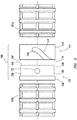
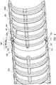
- FIGS. 2-4 depict duct coupler assembly 100 in accordance with embodiments of the present disclosure.
- Duct coupler assembly 100 may include female duct coupler 111 coupled to first duct segment 101a and male duct coupler 131 coupled to second duct segment 101b.
- Female duct coupler 111 and male duct coupler 131 may be separably coupleable, i.e., female duct coupler 111 and male duct coupler 131 may be uncoupled after being coupled.
- female duct coupler 111 and male duct coupler 131 may be coupled to the respective duct segment 101a and 101b, for example and without limitation, press fitting, mechanical welding, chemical welding, friction welding, thermal coupling, thermal welding, a shrink sleeve, an O-ring or diametric seal, or one or more adhesives.
- one or both of female duct coupler 111 or male duct coupler 131 may be formed integrally as the end of the respective duct segment 101a, 101b.
- female duct coupler 111 may be coupled to first duct segment 101a after first concrete element 20a is formed.
- female duct coupler 111 and male duct coupler 131 with respect to duct segments 101a and 101b discussed is merely exemplary and not intended to be limiting.
- Either duct coupler i.e. female duct coupler 111 or male duct coupler 131, may be coupled to either duct segment without deviating from the scope of this disclosure.
- female duct coupler 111 may include female duct coupler body 113.
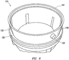
- male duct coupler 131 may include male duct coupler body 133.
- outer surface 139 of male duct coupler body 133 may have an outer diameter smaller than the inner diameter of inner surface 147 of the female duct coupler body 113 such that at least a portion of male duct coupler body 133 may fit within female duct coupler body 113.
- male duct coupler 131 may include male coupler flange 135 positioned to abut female edge 115 of female duct coupler 111, resisting further insertion of male duct coupler body 133 into female duct coupler body 113 as discussed further below.
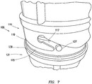
- female duct coupler 111 may include bayonet slot 117.
- Bayonet slot 117 may be formed as a slot in female duct coupler body 113.
- bayonet slot 117 may extend from female edge 115 of female duct coupler 111.
- Bayonet slot 117 may be formed along a generally helical path in female duct coupler body 113.
- male duct coupler 131 may include bayonet post 137.
- Bayonet post 137 may extend from the outer surface 139 of male duct coupler body 133.
- bayonet post 137 may be aligned with bayonet slot 117 as depicted in FIG. 7 and pressed thereinto.
- bayonet post 137 may follow the helical path of bayonet slot 117, drawing male duct coupler body 133 further into female duct coupler body 113 as depicted in FIG. 2 .
- bayonet slot 117 may include a flat or detent 119, shown in detail in FIG. 5 , positioned to retain bayonet post 137 in bayonet slot 117.
- flat or detent 119 may retain bayonet post 137 by elastic tension between female duct coupler body 113 and male duct coupler body 133.
- female duct coupler 111 may further include inner flange 121.
- Inner flange 121 may be positioned within female duct coupler body 113.
- Inner flange 121 may have outer surface 121a having an outer diameter smaller than the inner diameter of inner surface 133a of male duct coupler body 133.
- inner flange 121 may form seal groove 123.
- Male edge 141 of male duct coupler 131 may enter seal groove 123.
- a seal body 125 such as an O-ring or other gasket, may be positioned within seal groove 123 to form a seal against male edge 141 of male duct coupler 131.
- first concrete element 20a may be formed with first duct segment 101a positioned therein.
- first duct end 102 of first duct segment 101a may extend past end 21 of first concrete element end 21 of first concrete element 20a.
- Form 40 may be constructed or positioned next to first concrete element 20a as depicted in FIG. 8B .
- a first duct coupler of duct coupler assembly 100 here depicted as female duct coupler 111 may be provided and coupled to first duct segment 101a as depicted in FIG. 8C .
- a second duct coupler of duct coupler assembly 100 here depicted as male duct coupler 131 may be coupled to second duct segment 101b.
- male duct coupler 131 may be coupled to first duct segment 101a and female duct coupler 111 may be coupled to second duct segment 101b without deviating from the scope of this disclosure.
- male duct coupler 131 may be inserted into female duct coupler 111, and male duct coupler 131 and second duct segment 101b may be rotated as described herein to lock male duct coupler 131 to female duct coupler 111.
- second concrete element 20b may then be formed within form 40 by, for example and without limitation, pouring.
- duct coupler assembly 100 may be used to couple duct segments 101a and 101b in a single concrete element without deviating from the scope of this disclosure.
- female duct coupler 111 and male duct coupler 131 need not be circular without deviating from the scope of this disclosure.
- female duct coupler 111 and male duct coupler 131 may be circular, ellipsoidal, triangular, square, or any other shape in cross section.
Landscapes
- Engineering & Computer Science (AREA)
- General Engineering & Computer Science (AREA)
- Mechanical Engineering (AREA)
- Architecture (AREA)
- Civil Engineering (AREA)
- Structural Engineering (AREA)
- Manufacturing & Machinery (AREA)
- Chemical & Material Sciences (AREA)
- Ceramic Engineering (AREA)
- Quick-Acting Or Multi-Walled Pipe Joints (AREA)
- On-Site Construction Work That Accompanies The Preparation And Application Of Concrete (AREA)
- Lining And Supports For Tunnels (AREA)
Priority Applications (1)
| Application Number | Priority Date | Filing Date | Title |
|---|---|---|---|
| EP22150601.7A EP4001542B1 (de) | 2016-02-04 | 2017-01-12 | Bajonettröhrenkuppleranordnung |
Applications Claiming Priority (2)
| Application Number | Priority Date | Filing Date | Title |
|---|---|---|---|
| US201662291247P | 2016-02-04 | 2016-02-04 | |
| US15/402,826 US10634271B2 (en) | 2016-02-04 | 2017-01-10 | Bayonet duct coupler assembly for post-tensioned concrete member |
Related Child Applications (2)
| Application Number | Title | Priority Date | Filing Date |
|---|---|---|---|
| EP22150601.7A Division-Into EP4001542B1 (de) | 2016-02-04 | 2017-01-12 | Bajonettröhrenkuppleranordnung |
| EP22150601.7A Division EP4001542B1 (de) | 2016-02-04 | 2017-01-12 | Bajonettröhrenkuppleranordnung |
Publications (2)
| Publication Number | Publication Date |
|---|---|
| EP3202994A1 true EP3202994A1 (de) | 2017-08-09 |
| EP3202994B1 EP3202994B1 (de) | 2022-03-16 |
Family
ID=57821815
Family Applications (2)
| Application Number | Title | Priority Date | Filing Date |
|---|---|---|---|
| EP22150601.7A Active EP4001542B1 (de) | 2016-02-04 | 2017-01-12 | Bajonettröhrenkuppleranordnung |
| EP17151184.3A Active EP3202994B1 (de) | 2016-02-04 | 2017-01-12 | System zur schaffung einer nachgespanntes betonstruktur |
Family Applications Before (1)
| Application Number | Title | Priority Date | Filing Date |
|---|---|---|---|
| EP22150601.7A Active EP4001542B1 (de) | 2016-02-04 | 2017-01-12 | Bajonettröhrenkuppleranordnung |
Country Status (4)
| Country | Link |
|---|---|
| US (2) | US10634271B2 (de) |
| EP (2) | EP4001542B1 (de) |
| CA (1) | CA2954818C (de) |
| ES (2) | ES2916222T3 (de) |
Cited By (1)
| Publication number | Priority date | Publication date | Assignee | Title |
|---|---|---|---|---|
| EP3574736A1 (de) * | 2018-06-01 | 2019-12-04 | Deere & Company | Werkzeugfreie kupplungsstruktur in landwirtschaftlichen maschinen |
Families Citing this family (5)
| Publication number | Priority date | Publication date | Assignee | Title |
|---|---|---|---|---|
| US10519659B2 (en) * | 2017-06-13 | 2019-12-31 | Tindall Corporation | Methods and apparatuses for connecting concrete structural elements |
| CN110541817A (zh) * | 2019-09-17 | 2019-12-06 | 苏州沃达园林机械有限公司 | 一种防松脱的快速管接头 |
| US11255096B2 (en) * | 2019-11-25 | 2022-02-22 | Lugo Designs LLC | Sealing connector for post tensioned anchor system |
| US12085210B2 (en) * | 2020-01-17 | 2024-09-10 | Sierra Nevada Company, Llc | Aircraft tail lock |
| CN113294609A (zh) * | 2021-07-06 | 2021-08-24 | 苏州沃达园林机械有限公司 | 一种卡钩式快速接头装置 |
Citations (6)
| Publication number | Priority date | Publication date | Assignee | Title |
|---|---|---|---|---|
| FR1377585A (fr) * | 1963-09-26 | 1964-11-06 | Perfectionnements aux dispositifs de raccordement à baïonnette pour tuyaux souples | |
| US20030034651A1 (en) * | 2001-08-14 | 2003-02-20 | Frankische Rohrwerke Gebr. Kirchner Gmbh + Co Kg | Corrugated plastic pipe arrangement |
| US6764105B1 (en) * | 2002-05-07 | 2004-07-20 | Felix L. Sorkin | Duct coupler apparatus for use with precast concrete segmental construction |
| WO2010025877A1 (de) * | 2008-09-05 | 2010-03-11 | Lactocorder Ag | Schlauchkupplung |
| US20110179590A1 (en) * | 2010-01-28 | 2011-07-28 | David Andrew Klimas | Swimming Pool Cleaners, and Associated Hoses and Connectors for Use with the Same |
| US20150330078A1 (en) * | 2014-05-19 | 2015-11-19 | Felix Sorkin | Cap for Anchor of Post-Tension Anchorage System |
Family Cites Families (42)
| Publication number | Priority date | Publication date | Assignee | Title |
|---|---|---|---|---|
| US3104896A (en) * | 1963-09-24 | Pipe coupling with jistermeshing teeth | ||
| US555733A (en) * | 1896-03-03 | John s | ||
| US551733A (en) * | 1895-12-17 | Pipe-coupling | ||
| US913484A (en) * | 1907-09-05 | 1909-02-23 | James H Dove | Detachable coupling. |
| US2230098A (en) * | 1938-06-30 | 1941-01-28 | Patex Sa | Coupling for tubes and pipes |
| US2591531A (en) * | 1948-07-26 | 1952-04-01 | Edward W Fishback | Pipe coupling |
| US3248129A (en) * | 1963-08-14 | 1966-04-26 | Cicero C Brown | Dual release safety joint |
| CH482143A (de) * | 1969-02-20 | 1969-11-30 | Sebastiani Fa M | Lösbare Leitungskupplung |
| US4140422A (en) * | 1976-10-08 | 1979-02-20 | Crumpler Jr Houston L | Plastic corrugated drainage pipe |
| US4306743A (en) * | 1980-03-24 | 1981-12-22 | Hinshaw William E | Safety connection for breathing tubes |
| US4708370A (en) * | 1985-11-14 | 1987-11-24 | Toddco | Recreational vehicle discharge pipe coupler |
| JPH07199109A (ja) | 1993-10-14 | 1995-08-04 | Xerox Corp | ラスタースキャニングシステム |
| US5474335A (en) | 1994-08-17 | 1995-12-12 | Sorkin; Felix L. | Duct coupler with hinge interconnected locking rings |
| JPH09257175A (ja) * | 1996-03-25 | 1997-09-30 | Tokai Rubber Ind Ltd | 接続管及び管体の接続方法 |
| US5775849A (en) | 1996-04-25 | 1998-07-07 | Sorkin; Felix L. | Coupler for ducts used in post-tension rock anchorage systems |
| JP3372439B2 (ja) | 1996-10-11 | 2003-02-04 | 株式会社不二工機 | 膨張弁 |
| US5954373A (en) | 1998-03-16 | 1999-09-21 | Sorkin; Felix L. | Duct coupler apparatus |
| US6206433B1 (en) * | 1999-06-29 | 2001-03-27 | Siemens Canada Limited | Combustion air conduit coupling |
| US6659135B2 (en) | 2000-12-29 | 2003-12-09 | Felix L. Sorkin | Tendon-receiving duct with longitudinal channels |
| US6889714B1 (en) | 2000-12-29 | 2005-05-10 | Felix L. Sorkin | Tendon receiving duct for a monostrand bonded post-tension system |
| US8773351B2 (en) | 2001-05-21 | 2014-07-08 | Sony Corporation | User input apparatus, computer connected to user input apparatus, method of controlling computer connected to user input apparatus, and storage medium |
| US6550816B1 (en) | 2002-01-25 | 2003-04-22 | Felix L. Sorkin | Grout vent for a tendon-receiving duct |
| US6874821B1 (en) | 2002-05-07 | 2005-04-05 | Felix L. Sorkin | Coupler apparatus for use with angled post-tension cables in precast concrete segmental construction |
| US6752435B1 (en) | 2002-05-07 | 2004-06-22 | Felix L. Sorkin | Symmetrical coupler apparatus for use with precast concrete segmental construction |
| US6834890B2 (en) | 2002-05-07 | 2004-12-28 | Felix L. Sorkin | Coupler apparatus for use with a tendon-receiving duct in a segmental precast concrete structure |
| US6843031B1 (en) | 2003-07-17 | 2005-01-18 | Felix L. Sorkin | Bonded monostrand post-tension system |
| US7267375B1 (en) | 2004-10-25 | 2007-09-11 | Sorkin Felix L | Duct coupler apparatus |
| US7273238B1 (en) | 2004-10-25 | 2007-09-25 | Sorkin Felix L | Duct coupler apparatus with compressible seals |
| US7621103B1 (en) | 2004-11-08 | 2009-11-24 | Sorkin Felix L | Duct system for profiled post-tension construction |
| US20070252389A1 (en) * | 2006-04-27 | 2007-11-01 | Dywidag-Systems International | Duct Coupling Assembly |
| US7695021B1 (en) | 2007-09-25 | 2010-04-13 | Sorkin Felix L | Gasketed coupler apparatus for use with concrete segments |
| US8016326B1 (en) | 2007-09-25 | 2011-09-13 | Sorkin Felix L | Mandrel system for fixing an orientation of a duct in concrete segmental construction |
| US7686347B1 (en) | 2007-09-25 | 2010-03-30 | Sorkin Felix L | Couplers for use with ducts of concrete segmental construction |
| US9423059B1 (en) | 2009-02-17 | 2016-08-23 | Felix L. Sorkin | Duct coupler for segmental construction |
| US8398123B1 (en) | 2010-04-09 | 2013-03-19 | Felix L. Sorkin | Duct coupling system |
| US9803788B1 (en) * | 2011-03-28 | 2017-10-31 | Felix L. Sorkin | Press-on duct coupler assembly |
| US20120298248A1 (en) * | 2011-05-26 | 2012-11-29 | Guido Schwager | Tendon duct, duct connector and duct termination therefor |
| US8640292B1 (en) | 2012-05-21 | 2014-02-04 | Felix L. Sorkin | Deviator system for use in post-tension segmental concrete construction |
| US20150211665A1 (en) * | 2013-07-01 | 2015-07-30 | Felix L. Sorkin | Duct coupler for use with ducts in a wet joint of segmental concrete construction |
| US20150097369A1 (en) * | 2013-10-03 | 2015-04-09 | GM Global Technology Operations LLC | Duct connection system |
| ES2956236T3 (es) | 2014-05-19 | 2023-12-15 | Felix L Sorkin | Acoplador de conductos para elementos de hormigón postensado |
| US9399869B2 (en) | 2014-07-11 | 2016-07-26 | Felix Sorkin | Apparatus and method for connecting a segmental coupler to a steel plate or anchor casting |
-
2017
- 2017-01-10 US US15/402,826 patent/US10634271B2/en active Active
- 2017-01-12 CA CA2954818A patent/CA2954818C/en active Active
- 2017-01-12 ES ES17151184T patent/ES2916222T3/es active Active
- 2017-01-12 EP EP22150601.7A patent/EP4001542B1/de active Active
- 2017-01-12 ES ES22150601T patent/ES2977293T3/es active Active
- 2017-01-12 EP EP17151184.3A patent/EP3202994B1/de active Active
-
2020
- 2020-03-20 US US16/825,804 patent/US11603953B2/en active Active
Patent Citations (6)
| Publication number | Priority date | Publication date | Assignee | Title |
|---|---|---|---|---|
| FR1377585A (fr) * | 1963-09-26 | 1964-11-06 | Perfectionnements aux dispositifs de raccordement à baïonnette pour tuyaux souples | |
| US20030034651A1 (en) * | 2001-08-14 | 2003-02-20 | Frankische Rohrwerke Gebr. Kirchner Gmbh + Co Kg | Corrugated plastic pipe arrangement |
| US6764105B1 (en) * | 2002-05-07 | 2004-07-20 | Felix L. Sorkin | Duct coupler apparatus for use with precast concrete segmental construction |
| WO2010025877A1 (de) * | 2008-09-05 | 2010-03-11 | Lactocorder Ag | Schlauchkupplung |
| US20110179590A1 (en) * | 2010-01-28 | 2011-07-28 | David Andrew Klimas | Swimming Pool Cleaners, and Associated Hoses and Connectors for Use with the Same |
| US20150330078A1 (en) * | 2014-05-19 | 2015-11-19 | Felix Sorkin | Cap for Anchor of Post-Tension Anchorage System |
Cited By (2)
| Publication number | Priority date | Publication date | Assignee | Title |
|---|---|---|---|---|
| EP3574736A1 (de) * | 2018-06-01 | 2019-12-04 | Deere & Company | Werkzeugfreie kupplungsstruktur in landwirtschaftlichen maschinen |
| US11684006B2 (en) | 2018-06-01 | 2023-06-27 | Deere & Company | Tool-free coupling structure in agricultural machines |
Also Published As
| Publication number | Publication date |
|---|---|
| US20170227154A1 (en) | 2017-08-10 |
| US11603953B2 (en) | 2023-03-14 |
| ES2916222T3 (es) | 2022-06-29 |
| ES2977293T3 (es) | 2024-08-21 |
| EP3202994B1 (de) | 2022-03-16 |
| US10634271B2 (en) | 2020-04-28 |
| US20200217439A1 (en) | 2020-07-09 |
| CA2954818A1 (en) | 2017-08-04 |
| EP4001542B1 (de) | 2024-02-28 |
| CA2954818C (en) | 2023-10-17 |
| EP4001542A1 (de) | 2022-05-25 |
Similar Documents
| Publication | Publication Date | Title |
|---|---|---|
| US11603953B2 (en) | Bayonet duct coupler assembly for post-tensioned concrete member | |
| EP3146248B1 (de) | Röhrenkupplung für nachgespanntes betonelement | |
| JP5598783B2 (ja) | 鉄筋カプラー | |
| US9869335B2 (en) | Bar coupler | |
| US7878730B2 (en) | Bar coupling apparatus and methods | |
| US20150322676A1 (en) | Splice sleeve with elliptical or compound curve cross section | |
| KR101498662B1 (ko) | 철근 이음새 커플링 | |
| KR101570867B1 (ko) | 고강도 원터치 철근 커플러 | |
| CN211690320U (zh) | 快速对接组件及快速对接机构 | |
| KR102149032B1 (ko) | 원터치 철근 커플러 | |
| KR101550383B1 (ko) | 원터치 철근 커플러 및 그 제조방법 | |
| CN219508998U (zh) | 钢筋快速连接装置 | |
| KR20220110882A (ko) | 원터치식 철근 커플러 | |
| KR102289809B1 (ko) | 철근 커넥터 | |
| KR20230100448A (ko) | 잔류변형량 최소화를 위한 철근이음용 원터치 커플러의 철근 록킹장치 | |
| KR101018287B1 (ko) | 철근 연결장치 | |
| TWM404865U (en) | Groove-connected buckling-restrained brace device | |
| KR20130062531A (ko) | 관 커플링장치 | |
| CN111206618A (zh) | 一种预制装配式的矩形顶管及其施工方法 |
Legal Events
| Date | Code | Title | Description |
|---|---|---|---|
| PUAI | Public reference made under article 153(3) epc to a published international application that has entered the european phase |
Free format text: ORIGINAL CODE: 0009012 |
|
| STAA | Information on the status of an ep patent application or granted ep patent |
Free format text: STATUS: THE APPLICATION HAS BEEN PUBLISHED |
|
| AK | Designated contracting states |
Kind code of ref document: A1 Designated state(s): AL AT BE BG CH CY CZ DE DK EE ES FI FR GB GR HR HU IE IS IT LI LT LU LV MC MK MT NL NO PL PT RO RS SE SI SK SM TR |
|
| AX | Request for extension of the european patent |
Extension state: BA ME |
|
| STAA | Information on the status of an ep patent application or granted ep patent |
Free format text: STATUS: REQUEST FOR EXAMINATION WAS MADE |
|
| 17P | Request for examination filed |
Effective date: 20180118 |
|
| RBV | Designated contracting states (corrected) |
Designated state(s): AL AT BE BG CH CY CZ DE DK EE ES FI FR GB GR HR HU IE IS IT LI LT LU LV MC MK MT NL NO PL PT RO RS SE SI SK SM TR |
|
| STAA | Information on the status of an ep patent application or granted ep patent |
Free format text: STATUS: EXAMINATION IS IN PROGRESS |
|
| 17Q | First examination report despatched |
Effective date: 20200827 |
|
| GRAP | Despatch of communication of intention to grant a patent |
Free format text: ORIGINAL CODE: EPIDOSNIGR1 |
|
| STAA | Information on the status of an ep patent application or granted ep patent |
Free format text: STATUS: GRANT OF PATENT IS INTENDED |
|
| INTG | Intention to grant announced |
Effective date: 20211001 |
|
| GRAS | Grant fee paid |
Free format text: ORIGINAL CODE: EPIDOSNIGR3 |
|
| GRAA | (expected) grant |
Free format text: ORIGINAL CODE: 0009210 |
|
| STAA | Information on the status of an ep patent application or granted ep patent |
Free format text: STATUS: THE PATENT HAS BEEN GRANTED |
|
| AK | Designated contracting states |
Kind code of ref document: B1 Designated state(s): AL AT BE BG CH CY CZ DE DK EE ES FI FR GB GR HR HU IE IS IT LI LT LU LV MC MK MT NL NO PL PT RO RS SE SI SK SM TR |
|
| REG | Reference to a national code |
Ref country code: GB Ref legal event code: FG4D |
|
| REG | Reference to a national code |
Ref country code: CH Ref legal event code: EP |
|
| REG | Reference to a national code |
Ref country code: DE Ref legal event code: R096 Ref document number: 602017054559 Country of ref document: DE |
|
| REG | Reference to a national code |
Ref country code: IE Ref legal event code: FG4D |
|
| REG | Reference to a national code |
Ref country code: AT Ref legal event code: REF Ref document number: 1475978 Country of ref document: AT Kind code of ref document: T Effective date: 20220415 |
|
| REG | Reference to a national code |
Ref country code: ES Ref legal event code: FG2A Ref document number: 2916222 Country of ref document: ES Kind code of ref document: T3 Effective date: 20220629 |
|
| REG | Reference to a national code |
Ref country code: LT Ref legal event code: MG9D |
|
| REG | Reference to a national code |
Ref country code: NL Ref legal event code: MP Effective date: 20220316 |
|
| PG25 | Lapsed in a contracting state [announced via postgrant information from national office to epo] |
Ref country code: SE Free format text: LAPSE BECAUSE OF FAILURE TO SUBMIT A TRANSLATION OF THE DESCRIPTION OR TO PAY THE FEE WITHIN THE PRESCRIBED TIME-LIMIT Effective date: 20220316 Ref country code: RS Free format text: LAPSE BECAUSE OF FAILURE TO SUBMIT A TRANSLATION OF THE DESCRIPTION OR TO PAY THE FEE WITHIN THE PRESCRIBED TIME-LIMIT Effective date: 20220316 Ref country code: NO Free format text: LAPSE BECAUSE OF FAILURE TO SUBMIT A TRANSLATION OF THE DESCRIPTION OR TO PAY THE FEE WITHIN THE PRESCRIBED TIME-LIMIT Effective date: 20220616 Ref country code: LT Free format text: LAPSE BECAUSE OF FAILURE TO SUBMIT A TRANSLATION OF THE DESCRIPTION OR TO PAY THE FEE WITHIN THE PRESCRIBED TIME-LIMIT Effective date: 20220316 Ref country code: HR Free format text: LAPSE BECAUSE OF FAILURE TO SUBMIT A TRANSLATION OF THE DESCRIPTION OR TO PAY THE FEE WITHIN THE PRESCRIBED TIME-LIMIT Effective date: 20220316 Ref country code: BG Free format text: LAPSE BECAUSE OF FAILURE TO SUBMIT A TRANSLATION OF THE DESCRIPTION OR TO PAY THE FEE WITHIN THE PRESCRIBED TIME-LIMIT Effective date: 20220616 |
|
| REG | Reference to a national code |
Ref country code: AT Ref legal event code: MK05 Ref document number: 1475978 Country of ref document: AT Kind code of ref document: T Effective date: 20220316 |
|
| PG25 | Lapsed in a contracting state [announced via postgrant information from national office to epo] |
Ref country code: LV Free format text: LAPSE BECAUSE OF FAILURE TO SUBMIT A TRANSLATION OF THE DESCRIPTION OR TO PAY THE FEE WITHIN THE PRESCRIBED TIME-LIMIT Effective date: 20220316 Ref country code: GR Free format text: LAPSE BECAUSE OF FAILURE TO SUBMIT A TRANSLATION OF THE DESCRIPTION OR TO PAY THE FEE WITHIN THE PRESCRIBED TIME-LIMIT Effective date: 20220617 Ref country code: FI Free format text: LAPSE BECAUSE OF FAILURE TO SUBMIT A TRANSLATION OF THE DESCRIPTION OR TO PAY THE FEE WITHIN THE PRESCRIBED TIME-LIMIT Effective date: 20220316 |
|
| PG25 | Lapsed in a contracting state [announced via postgrant information from national office to epo] |
Ref country code: NL Free format text: LAPSE BECAUSE OF FAILURE TO SUBMIT A TRANSLATION OF THE DESCRIPTION OR TO PAY THE FEE WITHIN THE PRESCRIBED TIME-LIMIT Effective date: 20220316 |
|
| PG25 | Lapsed in a contracting state [announced via postgrant information from national office to epo] |
Ref country code: SM Free format text: LAPSE BECAUSE OF FAILURE TO SUBMIT A TRANSLATION OF THE DESCRIPTION OR TO PAY THE FEE WITHIN THE PRESCRIBED TIME-LIMIT Effective date: 20220316 Ref country code: SK Free format text: LAPSE BECAUSE OF FAILURE TO SUBMIT A TRANSLATION OF THE DESCRIPTION OR TO PAY THE FEE WITHIN THE PRESCRIBED TIME-LIMIT Effective date: 20220316 Ref country code: RO Free format text: LAPSE BECAUSE OF FAILURE TO SUBMIT A TRANSLATION OF THE DESCRIPTION OR TO PAY THE FEE WITHIN THE PRESCRIBED TIME-LIMIT Effective date: 20220316 Ref country code: PT Free format text: LAPSE BECAUSE OF FAILURE TO SUBMIT A TRANSLATION OF THE DESCRIPTION OR TO PAY THE FEE WITHIN THE PRESCRIBED TIME-LIMIT Effective date: 20220718 Ref country code: EE Free format text: LAPSE BECAUSE OF FAILURE TO SUBMIT A TRANSLATION OF THE DESCRIPTION OR TO PAY THE FEE WITHIN THE PRESCRIBED TIME-LIMIT Effective date: 20220316 Ref country code: CZ Free format text: LAPSE BECAUSE OF FAILURE TO SUBMIT A TRANSLATION OF THE DESCRIPTION OR TO PAY THE FEE WITHIN THE PRESCRIBED TIME-LIMIT Effective date: 20220316 Ref country code: AT Free format text: LAPSE BECAUSE OF FAILURE TO SUBMIT A TRANSLATION OF THE DESCRIPTION OR TO PAY THE FEE WITHIN THE PRESCRIBED TIME-LIMIT Effective date: 20220316 |
|
| PG25 | Lapsed in a contracting state [announced via postgrant information from national office to epo] |
Ref country code: PL Free format text: LAPSE BECAUSE OF FAILURE TO SUBMIT A TRANSLATION OF THE DESCRIPTION OR TO PAY THE FEE WITHIN THE PRESCRIBED TIME-LIMIT Effective date: 20220316 Ref country code: IS Free format text: LAPSE BECAUSE OF FAILURE TO SUBMIT A TRANSLATION OF THE DESCRIPTION OR TO PAY THE FEE WITHIN THE PRESCRIBED TIME-LIMIT Effective date: 20220716 Ref country code: AL Free format text: LAPSE BECAUSE OF FAILURE TO SUBMIT A TRANSLATION OF THE DESCRIPTION OR TO PAY THE FEE WITHIN THE PRESCRIBED TIME-LIMIT Effective date: 20220316 |
|
| REG | Reference to a national code |
Ref country code: DE Ref legal event code: R097 Ref document number: 602017054559 Country of ref document: DE |
|
| PLBE | No opposition filed within time limit |
Free format text: ORIGINAL CODE: 0009261 |
|
| STAA | Information on the status of an ep patent application or granted ep patent |
Free format text: STATUS: NO OPPOSITION FILED WITHIN TIME LIMIT |
|
| PG25 | Lapsed in a contracting state [announced via postgrant information from national office to epo] |
Ref country code: DK Free format text: LAPSE BECAUSE OF FAILURE TO SUBMIT A TRANSLATION OF THE DESCRIPTION OR TO PAY THE FEE WITHIN THE PRESCRIBED TIME-LIMIT Effective date: 20220316 |
|
| 26N | No opposition filed |
Effective date: 20221219 |
|
| PG25 | Lapsed in a contracting state [announced via postgrant information from national office to epo] |
Ref country code: SI Free format text: LAPSE BECAUSE OF FAILURE TO SUBMIT A TRANSLATION OF THE DESCRIPTION OR TO PAY THE FEE WITHIN THE PRESCRIBED TIME-LIMIT Effective date: 20220316 |
|
| P01 | Opt-out of the competence of the unified patent court (upc) registered |
Effective date: 20230613 |
|
| REG | Reference to a national code |
Ref country code: CH Ref legal event code: PL |
|
| PG25 | Lapsed in a contracting state [announced via postgrant information from national office to epo] |
Ref country code: LU Free format text: LAPSE BECAUSE OF NON-PAYMENT OF DUE FEES Effective date: 20230112 |
|
| REG | Reference to a national code |
Ref country code: BE Ref legal event code: MM Effective date: 20230131 |
|
| PG25 | Lapsed in a contracting state [announced via postgrant information from national office to epo] |
Ref country code: LI Free format text: LAPSE BECAUSE OF NON-PAYMENT OF DUE FEES Effective date: 20230131 Ref country code: CH Free format text: LAPSE BECAUSE OF NON-PAYMENT OF DUE FEES Effective date: 20230131 |
|
| PG25 | Lapsed in a contracting state [announced via postgrant information from national office to epo] |
Ref country code: BE Free format text: LAPSE BECAUSE OF NON-PAYMENT OF DUE FEES Effective date: 20230131 |
|
| PG25 | Lapsed in a contracting state [announced via postgrant information from national office to epo] |
Ref country code: IE Free format text: LAPSE BECAUSE OF NON-PAYMENT OF DUE FEES Effective date: 20230112 |
|
| PG25 | Lapsed in a contracting state [announced via postgrant information from national office to epo] |
Ref country code: MC Free format text: LAPSE BECAUSE OF FAILURE TO SUBMIT A TRANSLATION OF THE DESCRIPTION OR TO PAY THE FEE WITHIN THE PRESCRIBED TIME-LIMIT Effective date: 20220316 |
|
| PG25 | Lapsed in a contracting state [announced via postgrant information from national office to epo] |
Ref country code: MC Free format text: LAPSE BECAUSE OF FAILURE TO SUBMIT A TRANSLATION OF THE DESCRIPTION OR TO PAY THE FEE WITHIN THE PRESCRIBED TIME-LIMIT Effective date: 20220316 |
|
| PG25 | Lapsed in a contracting state [announced via postgrant information from national office to epo] |
Ref country code: CY Free format text: LAPSE BECAUSE OF FAILURE TO SUBMIT A TRANSLATION OF THE DESCRIPTION OR TO PAY THE FEE WITHIN THE PRESCRIBED TIME-LIMIT; INVALID AB INITIO Effective date: 20170112 |
|
| PG25 | Lapsed in a contracting state [announced via postgrant information from national office to epo] |
Ref country code: HU Free format text: LAPSE BECAUSE OF FAILURE TO SUBMIT A TRANSLATION OF THE DESCRIPTION OR TO PAY THE FEE WITHIN THE PRESCRIBED TIME-LIMIT; INVALID AB INITIO Effective date: 20170112 |
|
| PG25 | Lapsed in a contracting state [announced via postgrant information from national office to epo] |
Ref country code: TR Free format text: LAPSE BECAUSE OF FAILURE TO SUBMIT A TRANSLATION OF THE DESCRIPTION OR TO PAY THE FEE WITHIN THE PRESCRIBED TIME-LIMIT Effective date: 20220316 |
|
| PGFP | Annual fee paid to national office [announced via postgrant information from national office to epo] |
Ref country code: GB Payment date: 20260129 Year of fee payment: 10 |
|
| PGFP | Annual fee paid to national office [announced via postgrant information from national office to epo] |
Ref country code: ES Payment date: 20260210 Year of fee payment: 10 |
|
| PGFP | Annual fee paid to national office [announced via postgrant information from national office to epo] |
Ref country code: DE Payment date: 20260129 Year of fee payment: 10 |
|
| PGFP | Annual fee paid to national office [announced via postgrant information from national office to epo] |
Ref country code: IT Payment date: 20260128 Year of fee payment: 10 |
|
| PGFP | Annual fee paid to national office [announced via postgrant information from national office to epo] |
Ref country code: FR Payment date: 20260128 Year of fee payment: 10 |