EP3202995A1 - Water drain system with automatically adjustable discharge flow - Google Patents
Water drain system with automatically adjustable discharge flow Download PDFInfo
- Publication number
- EP3202995A1 EP3202995A1 EP16002151.5A EP16002151A EP3202995A1 EP 3202995 A1 EP3202995 A1 EP 3202995A1 EP 16002151 A EP16002151 A EP 16002151A EP 3202995 A1 EP3202995 A1 EP 3202995A1
- Authority
- EP
- European Patent Office
- Prior art keywords
- water
- closure body
- drainage system
- water drainage
- drain
- Prior art date
- Legal status (The legal status is an assumption and is not a legal conclusion. Google has not performed a legal analysis and makes no representation as to the accuracy of the status listed.)
- Granted
Links
Images

Classifications
-
- E—FIXED CONSTRUCTIONS
- E04—BUILDING
- E04D—ROOF COVERINGS; SKY-LIGHTS; GUTTERS; ROOF-WORKING TOOLS
- E04D13/00—Special arrangements or devices in connection with roof coverings; Protection against birds; Roof drainage ; Sky-lights
- E04D13/04—Roof drainage; Drainage fittings in flat roofs, balconies or the like
- E04D13/0404—Drainage on the roof surface
- E04D13/0409—Drainage outlets, e.g. gullies
- E04D2013/0427—Drainage outlets, e.g. gullies with means for controlling the flow in the outlet
Definitions
- the invention relates to a water drainage system, in particular a water drainage system for roof surfaces, and more particularly to such a system which prevents rainwater which falls on a surface from flowing away in a substantially undiminished amount and without a time delay.
- the sealing of the soil, especially in cities, means that the amount of water that falls during heavy rains can not be managed by the sewage system. As a consequence of this, floods of roads, sidewalks, etc. occur. Conventional building roofs drain the rainwater that has settled on them almost completely and without delay from the roof. In contrast, the discharge of rainwater from green roofs takes place with a time lag. The reason for this is that the plants and the substrate on which the plants are planted store rainwater and release it only after a delay. In addition, the amount of discharged water is lower because some of the rainfall evaporates over the bottom surface and another part is consumed by the plants.
- Green roofs therefore have the advantage over conventional, non-planted roofs that the precipitation that is deposited on them is released to the sewage system in a reduced amount and with a delay.
- the structure of the plant substrate for green roofs differs depending on the type of plants that are to be planted on the roof. Both single-layer and multilayer structures are known. Usually, as the plants become more demanding, the number of layers increases. If, for example, perennials, shrubs or trees are to be planted, multilayer constructions are usually required. and to provide the plants with sufficient water, a dewatering is necessary.
- a layer structure for such intensive greening thus comprises a water reservoir from which the plants can be continuously supplied with moisture.
- the water reservoir allows the absorption and retention of even larger amounts of water.
- the discharge coefficients set by the authorities that is, the permissible flow rate of water per time
- a precise adjustment of the discharge from the roof over time is required.
- the water drainage system described therein has concentric pipes which open into a roof drain and can be adjusted to one another in such a way that a limitation of the amount of water draining off is achieved.
- the flow rate is fixed depending on the size of the area to be drained, the type of roof structure and the expected amount of precipitation.
- the discharge coefficient C is based on a heavy precipitation event of 300 liters per second per hectare for a period of 15 minutes. This corresponds to the amount of 27 liters per square meter. According to the (currently) valid norms and precipitation data of the so-called Kostra-Atlas (statistical precipitation events, based on data of the German Weather Service (DWD)), 27 liters correspond in most cities and municipalities to a precipitation event, which varies regionally statistically once in the century or at least once in 50 years.
- the current systems are usually designed to meet the discharge coefficient C - ie ensure the predetermined water flow only for the prescribed period of 15 minutes or slightly beyond. After this period, however, the specified amount of water may then be exceeded again, that is, the amount of water fed into the sewage system increases again. If precipitation continues to fall, the green roof gradually absorbs like a sponge, and when fully saturated, the runoff coefficient increases to 1, which means that any further precipitation runs off the roof unhindered and completely.
- the object of the invention is accordingly to provide a water drainage system that meets these requirements, ensures a high water retention even with prolonged heavy rainfall events and ensures a flexible water balance.
- the invention relates, in a first aspect, to a water drainage system for a water footprint having a drain, in particular a roof surface comprising a closure body arranged inside or above the drain and designed to prevent the entry of water into the drain, an actuating device with which the closure body can be moved to allow the entry of water into the drain, and a control device for controlling the actuating device, which is designed to control the actuating device in dependence on evaluated weather data.
- the water drainage system makes it possible, by means of a control device and an actuating device, to use the closure body for the watertight closing of the drainage individually and as required.
- the closure body can be moved from a first, preventing the entry of water into the drainage position by means of the actuating device in a second position in which water can enter the drain.
- the present invention now also allows the flow rate not only according to the particular circumstances but also to change over time.
- the setting of the discharge amount is based on evaluated weather data.
- the invention not only allows individual planning and adjustment of the water storage amount on the water contact surface and the flow rate per time, but also allows an individual, targeted and continuous adjustment of the water balance over the entire operating time.
- the closure body can be designed such that it can be moved between a position completely closing the drain and a position completely releasing the drain.
- the controllability of the movement of the closure body and thus the flow rate per time also allows an adjustment in real time from an external location and therefore with a much lower cost than before.
- controllability in real time also enables a very rapid response to new environmental conditions such as extreme rainfall, a significant advantage of the invention is the ability to make predictive adjustments over the life of the water drainage system.
- the control device is therefore designed such that it controls the actuating device in dependence on externally received weather data, preferably weather forecast data, and in particular predicted precipitation amounts.
- weather data preferably weather forecast data, and in particular predicted precipitation amounts.
- weather data are available from various providers, for example in the form of so-called weather apps, which can be retrieved specifically for a specific given location.
- This weather data can either be transmitted via cable or, what is preferred, wirelessly to the water drainage system. Particularly preferred is the transmission of weather data by mobile phone.
- the reception device provided for receiving the weather data in the water drainage system is in this case then a mobile radio device, in particular a smartphone.
- a tablet PC or any other suitable receiving device.
- This is arranged at a suitable location in the water drainage system and connected to the control device, so that the weather data received by the receiving device can be transmitted to the control device.
- the transmission of data is preferably done here by means of cable, but also wireless transmission options are conceivable, such as a Bluetooth connection.
- the control is preferably carried out not only on the basis of the weather data for the current day, but taking into account the weather forecast data for at least the following day, preferably for several days in advance. In this way it is possible, for example, to make preparations for expected heavy rain events or longer periods of drought. For example, it can be calculated what memory requirements the precipitation to be expected for the following days need. In order to be able to absorb this expected volume of precipitation, it is optionally possible to clear storage volumes on the water contact area in order to make room for the new precipitation.
- the control of the water drainage system is carried out according to such that the actuator opens the closure body for a calculated period so far and the drain releases that runs from the water contact area as much water as the volume of the expected new precipitation corresponds.
- a margin of safety may also be provided to provide sufficient storage volume even when rainfall is actually greater than previously announced. If weather forecast data is taken into account for several days in advance, the discharge of the stored water from the water contact area can take place in good time so that the permitted drainage volume during discharge of the water to clear the storage volume is not exceeded before the occurrence of the expected heavy rainfall event. After the required amount of water has been drained from the water contact area (the calculated drain opening period has expired), a control signal is transmitted to the actuator by the control device, whereupon the actuator reduces or completely closes the drain by moving the closure body so that the forecast heavy rainfall, as soon as it begins to fall, it is collected and not or only with the allowed delay from the water contact surface is drained into the sewer.
- an irrigation system can be provided, which can also be controlled by the control device. This is set by the control device in operation when the water stored on the water drainage surface is no longer sufficient for irrigating a green roof.
- a water level indicator which either continuously transmits measured values to the control device or forwards a warning when the water level falls below a predetermined value.
- the control device puts the irrigation device into operation in order to ensure a sufficient supply of water to the planting.
- the water level indicator can also be independent of the presence an irrigation device are advantageously used to determine the water level on the water contact surface, so for example, in the above-described case for determining the available free storage volume in preparation for rains.
- Necessary data are, in particular, the data already used in the state of the art for the design of green roofs or gravel roofs with water retention, in particular data for calculating the maximum storage volume, the permissible flow rates, the retention capacity, etc.
- These stored data also include those of the discharge required by the authorities (eg allowable discharge rates in liters / second hectare or similar), the water contact surface (the area that can be used as a retention area), the so-called catchment areas (surrounding areas from which water reaches the water contact area can), the expected precipitation for the respective location (usually prescribed by the authorities precipitation parameters according to DIN standard or Kostra-Atlas for the design frequency of extreme weather events), the emptying time (period within which the calculated amounts of rainwater from the Retenti Ons vom run off), the accumulation height (resulting in the size of the retention surface, the volume of water absorbable), the number of processes in the water drainage area and the flow cross-section.
- the authorities eg allowable discharge rates in liters / second hectare or similar
- the water contact surface the area that can be used as a retention area
- catchment areas surrounding areas from which water reaches the water contact area can
- the expected precipitation for the respective location usually prescribed by the authorities precipitation parameters according to DIN standard or
- each of these outflows with an automatically actuated closure body according to the invention in order to control the outflow quantity of each of these outflows as a function of the evaluated weather data.
- the maximum opening cross section of the outflow opening for each individual outflow of the water drainage system according to the invention can be calculated with the parameters mentioned in addition to the maximum outflow cross section.
- values for the calculated evaporation and, for example, structural-static values can be included in the calculation and stored in the memory. Based on these values, the maximum accumulation volume and the maximum discharge rate per time can be calculated from the water contact surface.
- volume losses such as, for example, due to evaporation, preferably as a function of the outside temperature, can be taken into account.
- the basic design and basic settings of the water drainage system and their calculations correspond in principle to those of the prior art.
- the respective inflow volumes for the respective infeed areas and water contact areas known for the location can be determined by the weather app or other weather forecast predicted rainfall amounts are calculated.
- predicted precipitation values which are given in liters per square meter
- pre-calculated inflow volumes for the respective precipitation amounts for the respective location in the storage of the control unit can be stored in a certain period of time.
- These inflow volumes then again result in the storage volumes that have to be made available to absorb the forecast precipitation amounts.
- the amounts of water per time can be calculated, which must be drained from the water contact patch to make room for the expected rainfall.
- the actuating device is then actuated by the control device, which in turn opens the outflow in whole or in part for the calculated period in accordance with the calculated parameters by moving the closure body in order to discharge the calculated outflow volume.
- the drain is then completely or partially closed again (for example, depending on the given discharge coefficient) in order to be able to absorb the calculated precipitation volume.
- the calculations are calculated on the basis of values and calculation formulas stored in advance in the control device, taking into account the weather data transmitted externally.
- the computing center of an operator can be used for the calculation, which calculates the required control parameters for each location and then transmits the control parameters wired or wireless to the control device of the water drainage system according to the invention.
- the wireless transmission can, as already described above, be carried out by mobile phone, including a mobile device is installed in the water drainage system.
- the water drainage system comprises not only a receiver, but also a transmitter for transmitting messages and / or data to an external receiver.
- This transmitter is again preferably a mobile radio device, expediently the same mobile radio device that already serves as the receiver of the weather data.
- the transmitter specifically the mobile radio device, can serve on the one hand to input measured values of the system transfer external data center, where these measurements are used to calculate control data, which are then sent back to the mobile device of the water drainage system via mobile radio.
- the transmitter can also be used to send status messages and in particular error messages to an external receiver.
- maintenance or repair of the water drainage system can be carried out so quickly. Particularly preferably, this maintenance or repair by remote maintenance, so by external access to the control device and on this to the connected components, which significantly reduces the effort and costs.
- the water drainage system according to the invention is particularly suitable for use on gravel roofs or green roofs, hereinafter referred to briefly as green roofs.
- the water drainage system is in principle also suitable for use on other water footprints on which a certain volume of water for a certain period of time retained and / or delayed in time and controlled the sewer system should be fed.
- the water drainage system according to the invention is further explained below for use on a roof, in particular a green roof.
- the water contact surface is a roof surface that has a drain through which water is introduced into the sewer system. From its basic structure, the water drainage system according to the invention corresponds to those water drainage systems, as they have been used in the prior art, especially those, as shown in the DE 198 52 561 C1 are described.
- the water drainage system usually comprises a shaft which surrounds a cavity with its side walls. This shaft is placed above the drain on the roof surface.
- the shaft may have in its side walls immediately above the water contact surface passage openings, which allow unimpeded entry of located on the water contact surface water into the cavity of the shaft. If a particular water reservoir is to be maintained permanently on the water contact surface, the through-holes may also be located at a certain distance from the water contact surface in the side walls of the shaft, so that water can only enter the cavity when a certain water level is reached.
- the lower edge of the shaft should be placed as waterproof as possible on the roof surface in this case.
- an adhesive bond or seal is preferably arranged between the lower edge of the manhole and the roof surface.
- suitable gaskets include those used for sealing window frames in the soffit, for example, optionally self-adhesive butyl gaskets, compression bands (elastic closed cell foamed plastic tapes), and multi-component curable liquid plastic sealants, or combinations thereof.
- the lower edge of the shaft may be in the form of a flange.
- the seal is then conveniently attached to the side of the flange facing the roof surface.
- the formation of a water reservoir on the water contact surface can also be achieved by having a pipe around the drain or plugged into it, projecting above the water contact surface at a height corresponding to the desired head height of the water on the roof surface (see for example too DE 198 52 561 C1 ).
- the height depends, among other things, on the type of roof greening or gravel bedding chosen, and for green roofs is usually between 2 and 8 cm. From the footprint of the water on the roof surface and the damming height is calculated - possibly less the volume of other structures - the maximum water absorption volume of the roof surface.
- a closure body which prevents the ingress of water into the drain when it is in its closed position within or above the Outflow is arranged.
- it closes the inlet section to the drain completely, either by being plugged into the drain itself and closing it or by closing a pipe or other supply line, which opens into the drain.
- a closure body arranged within the drain it is sufficient if it is at least partially within the drain.
- "disposed within the drain” thus also includes a partial arrangement within the drain. In the simplest form, it may therefore be, for example, a plug which closes the inlet opening in the drain.
- the actuating device is designed to insert the plug for closing the drain in its inlet opening and to lift off from the inlet opening for opening.
- the plug can also be partially lifted from the inlet opening, so that an annular gap with a smaller opening cross section than the inlet opening results in total.
- a closure body arranged above the outflow is to be understood as meaning a closure body which covers the inlet cross-section of the outflow and / or completely circulates without being inserted into the drain.
- it could, for example, be a lid that lies above the inlet cross section of the drain.
- it could also be a arranged above the drain hollow body whose side walls are closed at least up to a certain height and thus prevent the ingress of water into the drain.
- the enclosed by the side walls of the inner surface of the hollow body is above the drain, that is, a cross section of the closure body covers the inlet cross section into the drain.
- the definition "above the drain” therefore does not necessarily mean that the closure body in any case completely above the inlet cross-section must be in the drain.
- the latter is especially the case when the inlet cross-section of the drain is located in the water contact area.
- the closure body suitably lies or stands on the water contact surface and prevents water from entering the drain from the sides.
- a closure body arranged above the drain can also be pulled down laterally around the pipe, for example down to the water start surface.
- the closure body extends over the inlet opening of the tube, which is also the inlet opening in the outflow, upwards and thus prevents the immediate entry of water into the pipe and from there into the drain when the maximum possible accumulation height of Water (according to the height of the tube) is reached.
- the closure body may be pot-shaped, the bottom of the pot extending above the inlet opening into the drain.
- the closure body it is also possible to form the closure body as an upwardly open hollow body, for example as a hollow cylinder. The walls of the hollow body are in the closed position in their height over the inlet opening of the drain before.
- the closure body acts only as long as a closure for the drain until the water level has reached the height of the walls of the hollow body on the water contact surface.
- NB The maximum water level is not the accumulation height of the permanent water reservoir, but a higher, higher water level beyond which, for example, water could pass over the building-side seals and thus damage the building itself could also be dictated by the static of the building.
- an emergency drain can be provided, which can be used for rapid removal of water from the roof structure when the maximum acceptable water level is exceeded.
- the closure body used according to the invention does not necessarily have to prevent the entry of water into the drain for all water levels on the water footprint. In the context of the invention, it is rather sufficient if the closure body prevents certain water levels, that water can pass unhindered into the drain. After exceeding a certain water level, it may even be desirable that the closure body allows an emergency drain, which prevents the further damming of water on the water contact surface.
- the closure body is arranged around a Wasseranstaurohr or the like around, it can be pushed directly onto the Wasseranstaurohr, as basically already in the DE 19852561 C1 is described. However, it is preferred if the closure body is arranged with a lateral distance to the Wasseranstaurohr.
- the closure body is designed as a hollow body and in particular as a hollow cylinder which rests in its closed position with its lower edge on the water contact surface.
- the lower wall portion is preferably folded laterally so as to give an enlarged contact surface.
- this support surface is substantially parallel to the water contact surface.
- the side wall of the hollow body is closed at least in its water contact area facing area and free of openings.
- the height of the side wall corresponds to the desired maximum water level on the water contact surface.
- the side wall extends beyond the maximum water level, but above the latter has at least one inlet opening through which water can enter the interior of the hollow body when the maximum water level is exceeded.
- the actuating device is preferably designed such that it can lift the closure body upwards from the inlet opening of the drain or move it to the side.
- the former is especially preferred.
- the flow rate can be influenced by how far the closure body is removed from the inlet opening and how large the gap between the closure body and the inlet opening is selected. The discharge rate is controlled accordingly over the time for which the closure body releases the drain.
- the actuating device with which the closure body is moved, can in principle be formed in any manner known and suitable from the prior art.
- Suitable components of the actuator include, for example, a cable mechanism, a pivot lever, a push or pull rod and / or a toothed or threaded rod. Suitable combinations of several of these elements are of course also possible.
- the type of drive is also not limited. In principle, any suitable movement device may be used, for example an electric motor, an electromagnetic, hydraulic or pneumatic drive. Because of the low maintenance susceptibility in the wet and strong temperature fluctuations exposed environment, the use of a pneumatic drive is preferred, which also has the advantage of a virtually wear and loss-free power transmission.
- an outer wall arranged on the water contact surface is arranged laterally around the closure body.
- This outer wall which in principle allows the entry of water into its interior and for this purpose has at least one passage opening, can serve, for example, to prevent or at least reduce the entry of impurities.
- the at least one passage opening is expediently provided with a particle filter, for example in the form of a sieve, a filter mat or another filter material.
- the outer wall of the attachment of parts of the actuator for the closure body and / or guide elements which guide and facilitate the movement of the closure body.
- the closure body is connected to at least one pivot lever, which is pivotally mounted on a support strut, which in turn is attached to the outer wall, which is arranged around the closure body.
- the pivoting of the pivot lever and thus the raising and lowering of the closure body is effected by movement of a push rod which acts on an arm of the pivot lever.
- the actuating device - as well as the control device an optionally present receiving or transmitting device, in particular in the form of a mobile device - expediently arranged inside a shaft located on the water contact surface.
- the upper end of the shaft remote from the roof surface, forms a service opening which allows access to the components of the water drainage system present in the cavity and hence their easy maintenance.
- This maintenance opening is conveniently closed with a removable or hinged lid.
- this lid is lockable, so that the components arranged in the shaft are protected not only from the weather, but also against access by unauthorized persons.
- a solar module mounted on the lid or alternatively raised in the vicinity of the shaft, a solar module can be provided, with which the power-consuming components of the water drainage system can be supplied with power.
- a power storage for example in the form of a battery.
- all components ie for Example actuator, control device, receiver and transmitter, supplied with solar power. In this way, a completely self-sufficient operation of the water drainage system is possible.
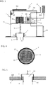
- FIG. 1 and 2 show water drainage systems 1 according to the invention, installed on a gravel roof and a green roof.
- gravel roof K is on the roof surface U which is also the water contact surface, applied a gravel pack k.
- a drain A through which water draining from the roof is supplied to the sewage system and which has a substantially circular inlet opening A1 lying in the plane of the water contact surface U, a shaft 7 is arranged, which encloses a cavity 71 and with a removable cover 70 is closed.
- the side walls of the shaft 7 have in the cross-sectional view not visible passage openings through which water can reach the interior 71 of the shaft 7.
- the shaft surrounded by the gravel corresponds in height to the height of the gravel pile k.
- the cover 70 is not covered with gravel and thus easily removable, whereby the cavity 71 of the shaft 7 is accessible.
- the water drainage system 1 according to the invention is arranged. This will be explained later.
- FIG. 2 Shown again is a cross section of a roof D in the region of a roof drain A. To protect the roof surface, some protective coverings SB are first applied to the roof surface U.
- a shaft 7 is set up with a water drainage system 1 according to the invention.
- the shaft 7 is connected watertight to the roof surface.
- the roof greening that surrounds the shaft is one with a permanent water reservoir WS. This is a cavity that can be filled with water and extends substantially over the entire roof area. This cavity is defined by pallet-like plastic hollow components, which are designed in a conventional manner over a large area on the roof surface.
- a drainage layer DS is applied, which is covered by a filter layer FS, which is to prevent the penetration of plant substrate PS in drainage layer and water storage. Perennials and shrubs are planted in the plant substrate. The water that serves to supply them is sucked upwards by capillary forces through the drainage layer out of the water reservoir and absorbed by the roots of the plants.
- the wall structure of the shaft 7 is such that the lower side wall 72 has no through-holes up to a height which substantially corresponds to the height of the water reservoir WS, so that water is dammed up to this height. At a height which substantially corresponds to the height of the drainage layer DS, the side wall 72 has a passage opening through which water can enter the interior 71 of the shaft.
- the upper part of the side wall, adjacent to the plant substrate PS, is in turn free of passage openings. This construction ensures that water can accumulate at the level of the water reservoir WS, however, an exceeding, unwanted increase in the amount of water in the green roofs on the drainage layer DS enter the interior of the shaft 7 and can be derived from there through the outflow A. , The closed upper part of the side wall 72 prevents the penetration of planting substrate into the shaft 7.
- the water reservoir WS is always sufficiently filled with water, on the other hand, but no waterlogging arises.
- the regulation of the water balance takes place with the aid of the water drainage system 1 according to the invention. This also makes it possible to regulate the water balance in a forward-looking manner, that is, for example, to drain water in advance from the water reservoir and from the roof surface U, if heavy rainfall is to be expected, which would exceed the storage capacity of an already at least partially filled water reservoir. This will be explained below with reference to FIGS. 1 to 3 be explained in more detail.
- the water drainage system 1 is in each case arranged in a shaft 7, which is placed above an outflow A on the water contact surface U.
- a part of the components of the water drainage system is arranged on an intermediate floor 73, which is mounted inside the shaft above the maximum water level.
- an actuating device 3 which moves the closure body 2 up or down.
- it may include a motor 38 that drives a pinion, which in turn moves a rack 33 up and down.
- the raising and lowering of the closure body 2 for example, by means of a push or threaded rod, a cable 31 or the like could take place.
- the control of the actuator 3 by means of a control device 4.
- the control device 4 can be operated either by means of an operating element, not shown here, such as a keyboard or a touch screen to manually send commands to the actuator 3 and / or retrieve information, etc.
- the purpose required programs, data, etc. are stored in a memory 40 of the control unit.
- a particular advantage of the water drainage system according to the invention is that it can also be operated from a remote location.
- a mobile phone / smartphone 5 which functions both as a receiving device and as a transmitter of the water drainage system and is connected by means of a data cable 50 to the control device 4.
- the control device 4 By selecting the mobile phone 5, it is possible to contact the control device 4 and to transmit to these commands or read data and / or messages.
- error messages issued by the control device 4 are transmitted via the mobile telephone 5 to a mobile telephone or another receiver of a user, so that the latter or a service provider can respond to the error message.
- the repair can in turn be done by remote maintenance via the mobile phone 5 to the control device 4, so that only in the rarest cases, a service technician on site must make a repair or maintenance.
- the described embodiment of the water drainage system 1 also makes it possible, in particular, to actuate the actuating device 3 via the control device 4 and thus to move the closure body 2 by manual influence and thus regulate the water balance on the roof from another location.
- a weather app is installed on the mobile phone, with which specific weather data for the location can be transmitted to the mobile phone 5.
- These weather data received by means of the mobile telephone 5 are then transmitted via the data cable 50 to the control device 4 and evaluated there.
- precipitation values stored in the memory 40 are compared with the precipitation values transmitted by the weather app.
- the deposited precipitation values are assigned corresponding total volumes, which must be included in the expected amount of precipitation per time corresponding to the catchment area of the roof in the water tank of the roof. For example, a forecast rainfall of x liters per square meter over the forecast period is associated with a volume of water to be absorbed of y liters over that period.
- These stored values are determined and stored in advance in a manner known per se specifically for the roof structure. Further values stored in the memory can include the retention surface specific to the roof structure, the maximum accumulation volume, specific evaporation values, the maximum drainage volume per time, the given retention values, such as the allowable discharge fee, the predetermined drainage coefficient, the predetermined retention time, etc., if necessary, structural Values or other data required for the water balance include.
- a water level indicator 10 in the area of the water reservoir, which also transmits values to the memory 40 of the control device 4. From these stored values, the parameters which are required for an optimal water balance in the green roof can be calculated by comparison with the expected precipitation values delivered by the weather app. Specifically, by comparing these values, parameters are determined with which by deliberately raising or lowering the closure body 2 so much water is accumulated in or drained from the water storage that on the one hand there is always a sufficient amount to supply the planting and, on the other hand, if heavy rainfall is expected , as much storage space is cleared in the water tank that the then falling rain can be absorbed in the water tank, without it comes to exceeding the maximum allowable or desired water level.
- the control device 4 causes the actuator 3 to lower the closure body 2 and the inlet A1 of the outlet A. close to catch the forecast for the current week rain in the water reservoir WS. The stored precipitate is then during the dry season the plants are available.
- Temperature values supplied by a temperature sensor 11 connected to the control device 4 can serve to take into account the loss of water due to evaporation and possibly increased water requirements of the planting at high temperatures in the calculation of the necessary quantities of water.
- the actuator is promptly before the onset of precipitation, the closure body 2 as long and to raise so far that a quantity of water drains from the roof, which at least corresponds to the expected precipitation.
- a solar module SM is arranged on the cover 70, which is associated with a power storage in the form of a battery AK.
- a power storage in the form of a battery AK.
- the connection between battery and consumers is not shown here for the sake of clarity.
- FIG. 1 shows a closure body 2 in the form of a narrowing on the outflow A peg, which in its closed position, the in FIG. 1 is shown with its lower end inserted into the drain and thus closes the inlet opening A1. Depending on how far the closure body 2 is lifted upwards, it can release the inlet opening A1 completely or partially (releasing an annular gap).
- FIG. 2 shows an alternative embodiment of a closure body 2, whose diameter is greater than the diameter of the inlet opening A1, so that the closure body 2 in its closed position covers the inlet opening A1 and closes in this way.
- the closure body could for example be arranged in lateral guide rails and with a push rod or another suitable movement device, which is controlled in a similar manner as described above by the control device.
- the closure body in FIG. 3 differs from the closure bodies of the Figures 1 and 2 in that it is not a massive body, but a hollow body. Specifically, a hollow cylinder is used here as the closure body, which is arranged above the inlet opening A1 of the outlet A such that its side wall completely encloses the inlet opening.
- FIG. 4 shown which is a cross-sectional view along the line XX of FIG. 3 is.
- the region 22 covered by the closure body 2 and shown here transversely striped is so large that it more than covers the opening cross-section A1 of the outflow A.
- this type of closure body is also called arranged above the drain. In its closed position, as in FIG.
- the hollow cylindrical closure body 2 prevents the entry of water into the drain A as long as the water level does not exceed the height of the side wall of the hollow cylinder.
- the height of the side wall of the hollow cylinder 2 is chosen so that it corresponds to the maximum desired or permissible water level on the water contact surface. If the water level continues to rise above this level, water flows over the edge of the hollow cylinder 2 and from there through the drain A. In this way, an emergency overflow can be realized, which works even if the closure body can no longer be lifted by means of the actuating device 3, which is here connected to a transverse strut of the closure body 2, due to a defect.
- FIG. 5 shows an alternative arrangement of in connection with FIG. 3
- the closure body 2 is used in a roof structure with permanent water storage WS, which is an alternative to that of FIG. 2 represents.indurcultivated openings in the side wall of the shaft 7 are not present here.
- the height of the permanent water reservoir WS is set in a manner known per se by means of a pipe A2, which is inserted with a corresponding projection into the drain A.
- the inlet A1 into the drain A is thus above the water contact surface U. Water can enter the drain A only when the water level exceeds the supernatant height of the tube A2. Also in this case, however, the outflow of water can be prevented by the outflow A is closed with the closure body 2.
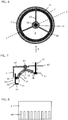
- FIGS. 6 to 8 describe a particularly preferred embodiment of a hollow body closure body 2.
- the arrangement above the outflow A basically corresponds to those associated with FIGS. 3 to 5 was discussed.
- the closure body 2 itself again essentially has a hollow cylindrical shape, in which case, however, the lower edge is folded over towards the interior of the hollow cylinder and forms a contact surface 21 substantially parallel to the water contact surface.
- the footprint 21 is provided over its entire surface with a layer 25 of an elastomeric plastic.
- the closure body 2 is arranged within an annular outer wall 6, which has slot-shaped passage openings 60 in its lower wall area towards the water contact area, through which water can pass into the interior.
- the openings 60 may be covered with a filter material to prevent dirt particles from entering the interior.
- the outer wall 6 serves for fastening parts of the actuating device for moving the closure body 2.
- a push rod 32 is guided, which is coupled to the drive means (for example, a motor) of the actuator 3 and can be moved in the direction of the double arrow up and down.
- a ring plate 37 is fixed, for example, between two screw nuts 36 which are screwed onto a thread at the lower end of the push rod.
- a pivot lever 30 is pivotally mounted on the annular plate 37.
- a fastening tab which projects upwards over the annular plate 37 is used.
- the pivot lever 30 has a curved shape. In about the middle, in the most prominent portion of the curvature, the pivot lever 30 has another hole through which a further bolt 35 is guided, which is attached to a fork-shaped holder 63.
- the fork bracket 63 is attached to one of the support struts 61.
- the outer end of the pivot lever 30 is also perforated, in the hole another pin 35 is inserted, and via this a second pivot lever 34 is pivotally connected to the pivot lever 30.
- pivot lever 34 By a perforation at its opposite end is the second pivot lever 34 movably attached to a fastening tab 24, which in turn is fixedly connected to the side wall 20 of the closure body 2.
- fastening tab 24 By a perforation at its opposite end is the second pivot lever 34 movably attached to a fastening tab 24, which in turn is fixedly connected to the side wall 20 of the closure body 2.
- pivot lever mechanisms On the two other support struts 61 pivot lever mechanisms are mounted in the same way.
- the lifting and lowering of the hollow cylinder closure body 2 is carried out by moving the push rod 32 up and down, which - driven by the control device 4 - is driven by the motor of the actuator. If the push rod 32, for example, pressed down, it follows the inner end of the pivot lever 30 which is mounted on the annular plate 37. The pivot lever 30 therefore pivots about the middle pin 35 which is supported on the fork bracket 63, and its outer end moves upward. As a result, the closure body 2, which is connected via the pivot lever 34 with the pivot lever 30, lifted upwards. When pulling the push rod 32, the pivoting operation is in the opposite direction, and the closure body 2 is lowered.
Landscapes
- Engineering & Computer Science (AREA)
- Architecture (AREA)
- Civil Engineering (AREA)
- Structural Engineering (AREA)
- Sewage (AREA)
Abstract
Die Erfindung betrifft ein Wasserabflusssystem (1) für eine einen Abfluss (A) aufweisende Wasseraufstandsfläche (U), insbesondere eine Dachfläche, umfassend: einen Verschlusskörper (2), welcher innerhalb oder oberhalb des Abflusses (A) angeordnet und ausgebildet ist, den Eintritt von Wasser in den Abfluss (A) zu verhindern, eine Betätigungsvorrichtung (3), mit welcher der Verschlusskörper (2) bewegt werden kann, um den Eintritt von Wasser in den Abfluss (A) zu erlauben, eine Steuervorrichtung (4) zum Steuern der Betätigungsvorrichtung (3), welche ausgebildet ist, die Betätigungsvorrichtung (3) in Abhängigkeit von ausgewerteten Wetterdaten zu steuern. Die Erfindung betrifft weiterhin ein das Wasserabflusssystem umfassendes Kies- oder Gründach sowie ein Verfahren zum Regulieren des Wasserstandes auf einer Wasseraufstandsfläche.The invention relates to a water drainage system (1) for a water contact surface (U) having a drain (A), in particular a roof surface, comprising: a closure body (2) which is arranged inside or above the outflow (A) and designed to prevent the entry of water into the outflow (A), an actuating device (3) with which the closure body (2) can be moved in order to allow the entry of water into the outflow (A), a control device (4) for controlling the actuating device (3), which is designed to control the actuating device (3) in dependence on evaluated weather data. The invention further relates to a gravel or green roof comprising the water drainage system and to a method for regulating the water level on a water contact surface.
Description
Die Erfindung betrifft ein Wasserabflusssystem, insbesondere ein Wasserabflusssystem für Dachflächen, und besonders ein solches System, welches verhindert, dass Regenwasser, welches auf einer Fläche niedergeht, in im Wesentlichen unverminderter Menge und ohne zeitliche Verzögerung abfließt.The invention relates to a water drainage system, in particular a water drainage system for roof surfaces, and more particularly to such a system which prevents rainwater which falls on a surface from flowing away in a substantially undiminished amount and without a time delay.
Die Versiegelung des Bodens führt insbesondere in Städten dazu, dass die bei starken Regenfällen niedergehende Wassermenge von der Kanalisation nicht bewältigt werden kann. Als Folge hiervon kommt es zu Überschwemmungen von Straßen, Bürgersteigen usw. Herkömmliche Gebäudebedachungen leiten das auf ihnen niedergegangene Regenwasser praktisch vollständig und ohne zeitliche Verzögerung vom Dach wieder ab. Dagegen erfolgt die Abgabe des Regenwassers von begrünten Dächern mit zeitlicher Verzögerung. Der Grund hierfür liegt darin, dass die Pflanzen und das Substrat, auf welchem die Pflanzen angepflanzt sind, Regenwasser speichern und nur verzögert abgeben. Zudem ist die Menge des abgegebenen Wassers geringer, da ein Teil der Niederschlagsmenge über die Bodenfläche verdunstet und ein anderer Teil von den Pflanzen verbraucht wird.The sealing of the soil, especially in cities, means that the amount of water that falls during heavy rains can not be managed by the sewage system. As a consequence of this, floods of roads, sidewalks, etc. occur. Conventional building roofs drain the rainwater that has settled on them almost completely and without delay from the roof. In contrast, the discharge of rainwater from green roofs takes place with a time lag. The reason for this is that the plants and the substrate on which the plants are planted store rainwater and release it only after a delay. In addition, the amount of discharged water is lower because some of the rainfall evaporates over the bottom surface and another part is consumed by the plants.
Gegenüber herkömmlichen, nicht bepflanzten Dächern weisen begrünte Dächer also den Vorteil auf, dass der auf ihnen niedergegangene Niederschlag in reduzierter Menge und mit zeitlicher Verzögerung an die Kanalisation abgegeben wird. Der Aufbau des Pflanzsubstrats für die Dachbegrünung unterscheidet sich je nach Art der Pflanzen, welche auf dem Dach angepflanzt werden sollen. Es sind sowohl ein- als auch mehrschichtige Aufbauten bekannt. Üblicherweise gilt, dass die Anzahl der Schichten zunimmt, je anspruchsvoller die Pflanzen werden. Sollen beispielsweise Stauden, Sträucher oder Bäume gepflanzt werden, sind üblicherweise mehrschichtige Aufbauten erforderlich, und um die Pflanzen hinreichend mit Wasser zu versorgen, ist eine Anstaubewässerung notwendig. Ein Schichtaufbau für eine derartige Intensivbegrünung umfasst also ein Wasserreservoir, aus dem die Pflanzen kontinuierlich mit Feuchtigkeit versorgt werden können.Green roofs therefore have the advantage over conventional, non-planted roofs that the precipitation that is deposited on them is released to the sewage system in a reduced amount and with a delay. The structure of the plant substrate for green roofs differs depending on the type of plants that are to be planted on the roof. Both single-layer and multilayer structures are known. Usually, as the plants become more demanding, the number of layers increases. If, for example, perennials, shrubs or trees are to be planted, multilayer constructions are usually required. and to provide the plants with sufficient water, a dewatering is necessary. A layer structure for such intensive greening thus comprises a water reservoir from which the plants can be continuously supplied with moisture.
Das Wasserreservoir ermöglicht die Aufnahme und den Rückhalt auch größerer Mengen Wasser. Um jedoch sicherzustellen, dass die von den Behörden vorgegebenen Abflussbeiwerte, dass heißt, die zulässige Ablaufmenge Wasser pro Zeit, auch bei starken Niederschlägen eingehalten wird, ist eine genaue Einstellung des Abflusses vom Dach über die Zeit erforderlich. In der
In letzter Zeit hat sich jedoch aufgrund des Klimawandels und der zunehmend verdichteten Bebauung die Situation verschlechtert, und die Überlastung der Kanalisationen und Gewässer hat sich verschärft. In der Folge kommt es mit zunehmender Häufigkeit zu Überflutungen und Hochwassern. Städte und Kommunen erhöhen zunehmend die Anforderungen an den Gebäudebesitzer, insbesondere bei Neubauten, einen Beitrag zur Überflutungs- und Hochwasservermeidung zu leisten. Die Grenzwerte für eine zulässige Einleitung von Abwasser in die Kanalisation werden immer weiter verschärft. Entsprechend steigen auch die Anforderungen an die Retentionsfähigkeit von Dachbegrünungen. So gibt es viele (Neu-)Baugebiete, bei denen Dachbegrünungen, zumeist mit einem festgelegten Abflussbeiwert C entsprechend der Forschungsgesellschaft Landschaftsentwicklung Landschaftsbau e. V. (FLL), über den Bebauungsplan vorgeschrieben werden. Zumeist wird hier ein Abflussbeiwert C von 0,5 oder 0,3 als Bemessung vorgesehen, was einem Abfluss von 50 bzw. 30 % im Vergleich zu einer versiegelten Flächen mit dem Abflussbeiwert 1 = 100 % entspricht.Recently, however, the situation has worsened due to climate change and increasingly dense development, and the congestion of the sewers and waterways has worsened. As a result, flooding and floods occur with increasing frequency. Cities and municipalities are increasingly increasing the demands on the building owner, in particular in new buildings, to make a contribution to flood and flood prevention. The limit values for a permissible discharge of wastewater into the sewage system are being further tightened. Accordingly, the requirements for the retention capacity of green roofs increase. So there are many (new) construction areas where green roofs, usually with a fixed discharge coefficient C according to the Research Association Landscape Development Landscaping e. V. (FLL), on the zoning plan. In most cases, a discharge coefficient C of 0.5 or 0.3 is provided as a design, which corresponds to an outflow of 50 or 30% compared to a sealed area with the
Dem Abflussbeiwert C wird ein Starkniederschlagsereignis von 300 Liter pro Sekunde und Hektar für eine Dauer von 15 Minuten zugrunde gelegt. Dieses entspricht der Menge von 27 Litern je Quadratmeter. 27 Liter entsprechen gemäß den (derzeitig) gültigen Normen und Niederschlagsdaten des sogenannten Kostra-Atlas (statistische Niederschlagereignisse, basierend auf Daten des Deutschen Wetterdienstes (DWD)) in den meisten Städten und Kommunen einem Niederschlagereignis, welches regional unterschiedlich statistisch einmal im Jahrhundert oder zumindest einmal in 50 Jahren eintritt. Allerdings kommen solche "jahrhundertereignisse" inzwischen wesentlich öfter vor, und weder die erst kürzlich an den Klimawandel angepasste DIN zur Bemessung der Wassermengen und notwendigen Dimensionierung der Entwässerungseinrichtungen noch der bald erscheinende überarbeitete Kostra-Atlas kommen der Realität wirklich nahe, sondern hinken systembedingt der Realität immer hinterher. Zudem sind die Entwässerungseinrichtungen, Kanalisationen etc. oft noch auf einem Stand von vor einigen Jahrzehnten, also in der Dimensionierung weder dem Klimawandel noch der zunehmenden Flächenversiegelung angepasst.The discharge coefficient C is based on a heavy precipitation event of 300 liters per second per hectare for a period of 15 minutes. This corresponds to the amount of 27 liters per square meter. According to the (currently) valid norms and precipitation data of the so-called Kostra-Atlas (statistical precipitation events, based on data of the German Weather Service (DWD)), 27 liters correspond in most cities and municipalities to a precipitation event, which varies regionally statistically once in the century or at least once in 50 years. However, such "century events" are now much more common, and neither the recently adapted to climate change DIN for the measurement of water volumes and necessary dimensioning of the drainage facilities nor the soon-to-be-reworked Kostra-Atlas really come close to reality, but are always systematically lagging behind reality. In addition, the drainage facilities, sewers, etc. are often still at a level of a few decades ago, so in the dimensioning neither climate change nor the increasing surface sealing adjusted.
Zunehmend werden daher im Auftrag von Städten und Kommunen schärfere Auflagen als bisher gemacht und konkrete Abflussmengen vorgegeben, die wesentlich geringer als die bisherigen Vorgaben nach Abflussbeiwert C sind. Beispielsweise werden Werte gefordert, die bei 1 bis 10 Litern Spitzenabfluss je Sekunde und Hektar liegen, und das über die gesamte Dauer des Abflusses. Hier kommen oft Werte heraus, die eine Ablaufverzögerung über 5 Stunden und mehr, vereinzelt sogar 24 Stunden und mehr ergeben. Gelegentlich werden auch Entleerungszeiten mit zum Beispiel 3, 6, 12 oder 24 Stunden vorgegeben. Wichtig ist hierbei auch, dass nicht nur die Dachflächen in die Berechnungen mit einbezogen werden, sondern das gesamte Grundstück, also auch weitere versiegelte Flächen wie Wege, Straßen und Hofflächen. Dies geht sehr weit über die bisherigen Anforderungen hinaus.Increasingly, on behalf of cities and municipalities, stricter requirements are being made than previously, and concrete discharge volumes have been specified which are significantly lower than the previous specifications according to discharge coefficient C. For example, values ranging from 1 to 10 liters per second per hectare are required over the entire duration of the runoff. Often, values come out that result in a delay of more than 5 hours and more, in some cases even 24 hours or more. Occasionally emptying times of, for example, 3, 6, 12 or 24 hours are given. It is also important that not only the roof surfaces are included in the calculations, but the entire property, including other sealed surfaces such as roads, roads and courtyard areas. This goes far beyond the previous requirements.
Mit den derzeit auf dem Markt befindlichen Dachbegrünungssystemen können die erhöhten Anforderungen bisher nicht befriedigt werden. Besonders die stark verlängerten Retentionszeiten werden üblicherweise nicht erreicht. Der Grund hierfür liegt unter anderem darin, dass die heutigen Systemen in der Regel zur Erfüllung des Abflussbeiwerts C ausgelegt sind - also den vorgegebenen Wasserablauf nur für den vorgeschriebenen Zeitraum von 15 Minuten oder wenig darüber hinaus sicherstellen. Nach Ablauf dieses Zeitraums darf die vorgegebene Wassermenge dann jedoch wieder überschritten werden, das heißt, die in die Kanalisation eingespeiste Wassermenge steigt wieder an. Fällt weiterhin Niederschlag, saugt sich die Dachbegrünung wie ein Schwamm allmählich voll, und bei völliger Sättigung steigt der Abflussbeiwert auf 1, was bedeutet, dass jeder weitere Niederschlag ungehindert und vollständig vom Dach abläuft. Um auch die verschärften Vorschriften eines besseren Wasserrückhalts über einen längeren Zeitraum zu erfüllen, bedarf es einer noch stärkeren Verzögerung, also Drosselung der Ablaufmengen, je nach Vorgaben gegebenenfalls über die gesamte Dauer eines Starkregenereignisses bzw. die gesamte Dauer das Wasserablaufes. Theoretisch wäre es denkbar, dieses Problem durch Erhöhung der Speicherkapazität zu lösen, jedoch stehen dem in der Regel bereits baustatische Beschränkungen im Wege.With the green roof systems currently on the market, the increased requirements can not be met. In particular, the greatly extended retention times are usually not achieved. The reason for this is, among other things, that the current systems are usually designed to meet the discharge coefficient C - ie ensure the predetermined water flow only for the prescribed period of 15 minutes or slightly beyond. After this period, however, the specified amount of water may then be exceeded again, that is, the amount of water fed into the sewage system increases again. If precipitation continues to fall, the green roof gradually absorbs like a sponge, and when fully saturated, the runoff coefficient increases to 1, which means that any further precipitation runs off the roof unhindered and completely. In order to meet the tightened regulations of a better water retention over a longer period, it requires an even stronger delay, so throttling the flow rates, depending on the requirements, if necessary, over the entire duration of a heavy rainfall event or the entire duration of the water flow. Theoretically, it would be conceivable to solve this problem by increasing the storage capacity, but this usually already stands in the way of structural restrictions.
Aufgabe der Erfindung ist es entsprechend, ein Wasserabflusssystem anzugeben, dass diesen Anforderungen entspricht, selbst bei länger andauernden Starkregenereignissen einen hohen Wasserrückhalt sicherstellt und einen flexiblen Wasserhaushalt gewährleistet.The object of the invention is accordingly to provide a water drainage system that meets these requirements, ensures a high water retention even with prolonged heavy rainfall events and ensures a flexible water balance.
Die Lösung dieser Aufgabe gelingt mit dem Wasserabflusssystem nach Anspruch 1, einem dieses System verwendenden Kies- oder Gründach nach Anspruch 12 und dem Verfahren zum Regulieren des Wasserstandes nach Anspruch 13. Bevorzugte Ausführungsformen sind in den abhängigen Ansprüchen beschrieben.The solution of this object is achieved with the water drainage system according to
Die Erfindung betrifft in einem ersten Aspekt ein Wasserabflusssystem für eine einen Abfluss aufweisende Wasseraufstandsfläche, insbesondere eine Dachfläche, umfassend einen Verschlusskörper, welcher innerhalb oder oberhalb des Abflusses angeordnet und ausgebildet ist, den Eintritt von Wasser in den Abfluss zu verhindern, eine Betätigungsvorrichtung, mit welcher der Verschlusskörper bewegt werden kann, um den Eintritt von Wasser in den Abfluss zu erlauben, und eine Steuervorrichtung zum Steuern der Betätigungsvorrichtung, welche ausgebildet ist, die Betätigungsvorrichtung in Abhängigkeit von ausgewerteten Wetterdaten zu steuern.The invention relates, in a first aspect, to a water drainage system for a water footprint having a drain, in particular a roof surface comprising a closure body arranged inside or above the drain and designed to prevent the entry of water into the drain, an actuating device with which the closure body can be moved to allow the entry of water into the drain, and a control device for controlling the actuating device, which is designed to control the actuating device in dependence on evaluated weather data.
Das erfindungsgemäße Wasserabflusssystem erlaubt es, mittels Steuervorrichtung und Betätigungsvorrichtung den Verschlusskörper zum wasserdichten Verschließen des Abflusses individuell und nach Bedarf einzusetzen. Hierfür kann der Verschlusskörper aus einer ersten, den Eintritt von Wasser in den Abfluss verhindernden Position mittels der Betätigungsvorrichtung in eine zweite Position bewegt werden, in der Wasser in den Abfluss eintreten kann. Anders als im eingangs beschriebenen Stand der Technik, bei dem es zwar möglich war, die Öffnungsgröße der Durchflussöffnung und damit die Abflussmenge pro Zeit entsprechend dem jeweiligen Gründach individuell fest vorzugeben, ermöglicht es die vorliegende Erfindung nun zusätzlich, die Abflussmenge nicht nur entsprechend den jeweiligen Gegebenheiten anzupassen, sondern auch über die Zeit zu verändern. Die Einstellung der Abflussmenge erfolgt dabei anhand von ausgewerteten Wetterdaten. Dadurch wird es beispielsweise möglich, bei sehr starken Regenfällen den Abfluss vollständig freizugeben, um so die Abflussmenge zeitlich begrenzt zu erhöhen. Zudem kann bei nachlassendem Niederschlag oder bei Trockenheit der Abfluss verkleinert oder ganz verschlossen werden, um zu verhindern, dass der Wasserspeicher auf der Wasseraufstandsfläche ganz geleert wird und beispielsweise für eine auf der Wasseraufstandsfläche vorhandene Dachbegrünung keine ausreichende Bewässerung mehr vorhanden ist.The water drainage system according to the invention makes it possible, by means of a control device and an actuating device, to use the closure body for the watertight closing of the drainage individually and as required. For this purpose, the closure body can be moved from a first, preventing the entry of water into the drainage position by means of the actuating device in a second position in which water can enter the drain. Unlike in the prior art described above, in which it was indeed possible to specify the opening size of the flow opening and thus the flow rate per time corresponding to the respective green roof individually, the present invention now also allows the flow rate not only according to the particular circumstances but also to change over time. The setting of the discharge amount is based on evaluated weather data. This makes it possible, for example, completely free the drain in very heavy rainfall, so as to increase the flow rate for a limited time. In addition, with decreasing rainfall or dryness of the drain can be reduced or completely closed to prevent the water reservoir is completely emptied on the water contact patch and, for example, for a present on the water contact surface green roof irrigation is no longer adequate.
Zusammengefasst kann also festgehalten werden, dass die Erfindung nicht nur eine individuellen Planung und Einstellung der Wasserspeichermenge auf der Wasseraufstandsfläche und der Ablaufmenge pro Zeit erlaubt, sondern zudem eine individuelle, gezielte und kontinuierliche Anpassung des Wasserhaushalts über die gesamte Betriebszeit ermöglicht. Der Verschlusskörper kann dabei so ausgebildet sein, dass er zwischen einer den Abfluss vollständig verschließenden Position und einer den Abfluss vollständig freigebenden Position bewegt werden kann. Zudem ist es möglich, den Verschlusskörper so auszubilden, dass er Zwischenpositionen einnehmen kann, in denen der Zufluss zum Abfluss teilweise freigegeben wird, so dass eine geringere Abflussmenge als bei vollständig freigegebenem Abfluss eingestellt werden kann. Die Steuerbarkeit der Bewegung des Verschlusskörpers und damit der Abflussmenge pro Zeit erlaubt zudem eine Anpassung praktisch in Echtzeit von einem externen Standort aus und daher mit einem erheblich geringeren Aufwand als bislang. Obwohl die Steuerbarkeit in Echtzeit auch eine sehr schnelle Reaktion auf neue Umgebungsbedingungen wie beispielsweise Extremregenfälle ermöglicht, liegt ein wesentlicher Vorteil der Erfindung in der Möglichkeit, vorausschauende Einstellungen über die Betriebsdauer des Wasserabflusssystems vornehmen zu können.In summary, it can be stated that the invention not only allows individual planning and adjustment of the water storage amount on the water contact surface and the flow rate per time, but also allows an individual, targeted and continuous adjustment of the water balance over the entire operating time. The closure body can be designed such that it can be moved between a position completely closing the drain and a position completely releasing the drain. In addition, it is possible to design the closure body so that it can assume intermediate positions in which the inflow to the outflow is partially released, so that a lower outflow quantity can be set than with completely released outflow. The controllability of the movement of the closure body and thus the flow rate per time also allows an adjustment in real time from an external location and therefore with a much lower cost than before. Although controllability in real time also enables a very rapid response to new environmental conditions such as extreme rainfall, a significant advantage of the invention is the ability to make predictive adjustments over the life of the water drainage system.
In einer bevorzugten Ausführungsform der Erfindung ist die Steuervorrichtung daher so ausgebildet, dass sie die Betätigungsvorrichtung in Abhängigkeit von extern empfangenen Wetterdaten, bevorzugt Wetterprognosedaten, und insbesondere prognostizierten Niederschlagsmengen steuert. - Zweckmäßig werden dabei Wetterdaten eingesetzt, die sich auf den jeweiligen Standort beziehen, an dem sich das erfindungsgemäße Wasserabflusssystem befindet. Solche Wetterdaten sind von verschiedenen Anbietern beispielsweise in Form von sogenannten Wetter-Apps verfügbar, die speziell für einen bestimmten vorgegebenen Standort abgerufen werden können. Diese Wetterdaten können entweder über Kabel oder, was bevorzugt ist, kabellos an des Wasserabflusssystem übertragen werden. Besonders bevorzugt ist die Übertragung der Wetterdaten per Mobilfunk. Das zum Empfang der Wetterdaten im Wasserabflusssystem vorgesehene Empfangsgerät ist in diesem Fall dann ein Mobilfunkgerät, insbesondere ein Smartphone. Es könnte sich jedoch auch um einen Tablet-PC oder jedes andere geeignete Empfangsgerät handeln. Dieses wird an einem geeigneten Ort im Wasserabflusssystem angeordnet und mit der Steuervorrichtung verbunden, so dass die vom Empfangsgerät empfangenen Wetterdaten an die Steuervorrichtung übertragen werden können. Die Übertragung der Daten geschieht hier bevorzugt mittels Kabel, jedoch sind auch kabellose Übertragungsmöglichkeiten denkbar, beispielsweise eine Bluetooth-Verbindung.In a preferred embodiment of the invention, the control device is therefore designed such that it controls the actuating device in dependence on externally received weather data, preferably weather forecast data, and in particular predicted precipitation amounts. - Expediently weather data are used, which refer to the respective location at which the water drainage system according to the invention is located. Such weather data are available from various providers, for example in the form of so-called weather apps, which can be retrieved specifically for a specific given location. This weather data can either be transmitted via cable or, what is preferred, wirelessly to the water drainage system. Particularly preferred is the transmission of weather data by mobile phone. The reception device provided for receiving the weather data in the water drainage system is in this case then a mobile radio device, in particular a smartphone. However, it could also be a tablet PC or any other suitable receiving device. This is arranged at a suitable location in the water drainage system and connected to the control device, so that the weather data received by the receiving device can be transmitted to the control device. The transmission of data is preferably done here by means of cable, but also wireless transmission options are conceivable, such as a Bluetooth connection.
Die Steuerung erfolgt bevorzugt nicht nur anhand der Wetterdaten für den aktuellen Tag, sondern unter Berücksichtigung der Wetterprognosedaten für mindestens den Folgetag, bevorzugt für mehrere Tage im Voraus. Auf diese Weise ist es beispielsweise möglich, Vorbereitungen für zu erwartende Starkregenereignisse oder längere Trockenperioden zu treffen. Beispielsweise kann errechnet werden, welchen Speicherbedarf die für die Folgetage zu erwartenden Niederschläge benötigen. Um dieses erwartete Niederschlagsvolumen aufnehmen zu können, kann gegebenenfalls Speichervolumen auf der Wasseraufstandsfläche freigemacht werden, um so Platz für die neuen Niederschläge zu schaffen. Die Steuerung des Wasserabflusssystems erfolgt entsprechend derart, dass die Betätigungsvorrichtung den Verschlusskörper für einen errechneten Zeitraum soweit öffnet und den Abfluss freigibt, dass von der Wasseraufstandsfläche soviel Wasser abläuft, wie dem Volumen der zu erwartenden neuen Niederschläge entspricht. Falls gewünscht, kann auch eine Sicherheitsmarge eingeplant werden, um für ausreichend Speichervolumen auch dann zu sorgen, wenn die Niederschläge tatsächlich größer werden als angekündigt. Werden Wetterprognosedaten für mehrere Tage im voraus berücksichtigt, kann das Ablassen des gespeicherten Wassers von der Wasseraufstandsfläche so rechtzeitig erfolgen, dass vor Eintritt des zu erwartenden Starkregenereignisses die erlaubte Abflussmenge während des Ablassens des Wassers zur Freimachung von Speichervolumen nicht überschritten wird. Nachdem die erforderliche Wassermenge von der Wasseraufstandsfläche abgelassen wurde (der errechnete Öffnungszeitraum für den Abfluss abgelaufen ist), wird der Betätigungsvorrichtung von der Steuervorrichtung ein Steuersignal übermittelt, worauf die Betätigungsvorrichtung den Abfluss durch Bewegen des Verschlusskörpers verkleinert oder vollständig verschließt, so dass der prognostizierte Starkregen, sobald er zu fallen beginnt, gesammelt wird und nicht oder nur mit der erlaubten Verzögerung von der Wasseraufstandsfläche in die Kanalisation abgeleitet wird.The control is preferably carried out not only on the basis of the weather data for the current day, but taking into account the weather forecast data for at least the following day, preferably for several days in advance. In this way it is possible, for example, to make preparations for expected heavy rain events or longer periods of drought. For example, it can be calculated what memory requirements the precipitation to be expected for the following days need. In order to be able to absorb this expected volume of precipitation, it is optionally possible to clear storage volumes on the water contact area in order to make room for the new precipitation. The control of the water drainage system is carried out according to such that the actuator opens the closure body for a calculated period so far and the drain releases that runs from the water contact area as much water as the volume of the expected new precipitation corresponds. If desired, a margin of safety may also be provided to provide sufficient storage volume even when rainfall is actually greater than previously announced. If weather forecast data is taken into account for several days in advance, the discharge of the stored water from the water contact area can take place in good time so that the permitted drainage volume during discharge of the water to clear the storage volume is not exceeded before the occurrence of the expected heavy rainfall event. After the required amount of water has been drained from the water contact area (the calculated drain opening period has expired), a control signal is transmitted to the actuator by the control device, whereupon the actuator reduces or completely closes the drain by moving the closure body so that the forecast heavy rainfall, as soon as it begins to fall, it is collected and not or only with the allowed delay from the water contact surface is drained into the sewer.
Umgekehrt kann bei einer erwarteten Trockenperiode das Abfließen von Wasser von der Wasseraufstandsfläche unterbrochen werden. Der Abfluss wird also geschlossen, sodass kein Wasser mehr abläuft und eventuell vor der angekündigten Trockenperiode noch fallender Regen gesammelt wird. In einer Weiterbildung der Erfindung kann ein Bewässerungssystem vorgesehen sein, das ebenfalls von der Steuervorrichtung gesteuert werden kann. Dieses wird von der Steuervorrichtung in Betrieb gesetzt, wenn das auf der Wasserablauffläche gespeicherte Wasser für die Bewässerung einer Dachbegrünung nicht mehr ausreicht. In einer bevorzugten Ausbildungsform der Erfindung kann zur Ermittlung der gespeicherten Wassermenge ein Wasserstandsanzeiger vorhanden sein, der entweder kontinuierlich Messwerte an die Steuervorrichtung übermittelt oder eine Warnung weiterleitet, wenn der Wasserstand unter einen vorgegebenen Wert fällt. Dann oder alternativ nach Ablauf einer vorgegebenen Zeit, innerhalb derer der Wasserstand sich nicht auf einen ausreichenden Wert erholt hat, setzt die Steuervorrichtung die Bewässerungsvorrichtung in Betrieb, um eine ausreichende Wasserversorgung der Bepflanzung zu sichern. Der Wasserstandsanzeiger kann auch unabhängig vom Vorhandensein einer Bewässerungsvorrichtung vorteilhaft zur Ermittlung des Wasserstandes auf der Wasseraufstandsfläche eingesetzt werden, also beispielsweise auch im vorgehend beschrieben Fall zur Ermittlung des zur Verfügung stehenden freien Speichervolumens in Vorbereitung auf Regenfälle.Conversely, at an expected dry period, the drainage of water from the water contact patch can be interrupted. The drain is therefore closed so that no more water expires and possibly before the announced dry period still falling rain is collected. In one development of the invention, an irrigation system can be provided, which can also be controlled by the control device. This is set by the control device in operation when the water stored on the water drainage surface is no longer sufficient for irrigating a green roof. In a preferred embodiment of the invention may be present for determining the stored amount of water, a water level indicator which either continuously transmits measured values to the control device or forwards a warning when the water level falls below a predetermined value. Then, or alternatively after a predetermined time has elapsed, within which the water level has not recovered to a sufficient value, the control device puts the irrigation device into operation in order to ensure a sufficient supply of water to the planting. The water level indicator can also be independent of the presence an irrigation device are advantageously used to determine the water level on the water contact surface, so for example, in the above-described case for determining the available free storage volume in preparation for rains.
Die zur Berechnung der Steuervorgänge notwendigen Informationen und Daten sind bevorzugt in der Steuervorrichtung, die hierfür einen geeigneten Speicher aufweist, hinterlegt. Notwendige Daten sind insbesondere die bereits aus dem Stand der Technik für die Auslegung von begrünten Dächern oder Kiesdächer mit Wasserretention verwendeten Daten wie insbesondere Daten zur Berechnung des maximalen Speichervolumens, der zulässigen Ablaufmengen, des Retentionsvermögens usw.. Zu diesen hinterlegten Daten gehören zweckmäßig auch die von den Behörden geforderte Abflussspende (z. B. erlaubte Ablaufmengen in Liter/Sekunde Hektar o. ä.), die Wasseraufstandsfläche (die Fläche, die als Retentionsfläche genutzt werden kann), die sogenannten Einzugsflächen (umliegende Flächen, von denen Wasser auf die Wasseraufstandsfläche gelangen kann), die für den jeweiligen Standort zu erwartenden Niederschläge (üblicherweise von den Behörden vorgegebene Niederschlagsparameter gemäß DIN-Norm oder Kostra-Atlas zur Bemessungshäufigkeit extremer Wetterereignisse), die Entleerungszeit (Zeitraum, innerhalb dessen die errechneten Niederschlagswassermengen von den Retentionsflächen abfließen dürfen), die Anstauhöhe (ergibt mit der Größe der Retentionsfläche das aufnehmbare Wasservolumen), die Anzahl der Abläufe in der Wasserablauffläche und der Ablaufquerschnitt. Befindet sich auf der Wasseraufstandsfläche mehr als ein Abfluss, wird zweckmäßig jeder dieser Abflüsse mit einem erfindungsgemäß automatisch betätigten Verschlusskörper versehen, um die Abflussmenge jedes dieser Abflüsse in Abhängigkeit von den ausgewerteten Wetterdaten zu steuern. In an sich bekannter Weise kann mit den genannten Parametern neben dem maximalen Ablaufquerschnitt auch der maximale Öffnungsquerschnitt der Abflussöffnung für jeden einzelnen Abfluss des erfindungsgemäßen Wasserabflusssystems errechnet werden. Weiterhin können Werte zur berechneten Verdunstung und beispielsweise baustatische Werte in die Berechnung mit einfließen und im Speicher hinterlegt sein. Anhand dieser Werte lassen sich das maximale Anstauvolumen und die maximale Abflussmenge pro Zeit von der Wasseraufstandsfläche errechnen. Weiterhin können Volumenveriuste wie beispielsweise durch Verdunstung, vorzugsweise in Abhängigkeit von der Außentemperatur, berücksichtigt werden. Die Grundauslegung und Grundeinstellungen des Wasserabflusssystems und deren Berechnungen entsprechen prinzipiell denjenigen des Standes der Technik.The information and data necessary for calculating the control processes are preferably stored in the control device, which has a suitable memory for this purpose. Necessary data are, in particular, the data already used in the state of the art for the design of green roofs or gravel roofs with water retention, in particular data for calculating the maximum storage volume, the permissible flow rates, the retention capacity, etc. These stored data also include those of the discharge required by the authorities (eg allowable discharge rates in liters / second hectare or similar), the water contact surface (the area that can be used as a retention area), the so-called catchment areas (surrounding areas from which water reaches the water contact area can), the expected precipitation for the respective location (usually prescribed by the authorities precipitation parameters according to DIN standard or Kostra-Atlas for the design frequency of extreme weather events), the emptying time (period within which the calculated amounts of rainwater from the Retenti Onsflächen run off), the accumulation height (resulting in the size of the retention surface, the volume of water absorbable), the number of processes in the water drainage area and the flow cross-section. If there is more than one outflow on the water contact surface, it is expedient to provide each of these outflows with an automatically actuated closure body according to the invention in order to control the outflow quantity of each of these outflows as a function of the evaluated weather data. In a manner known per se, the maximum opening cross section of the outflow opening for each individual outflow of the water drainage system according to the invention can be calculated with the parameters mentioned in addition to the maximum outflow cross section. Furthermore, values for the calculated evaporation and, for example, structural-static values can be included in the calculation and stored in the memory. Based on these values, the maximum accumulation volume and the maximum discharge rate per time can be calculated from the water contact surface. Furthermore, volume losses, such as, for example, due to evaporation, preferably as a function of the outside temperature, can be taken into account. The basic design and basic settings of the water drainage system and their calculations correspond in principle to those of the prior art.
Um den Speicherbedarf für die prognostizierten Niederschläge im voraus berechnen zu können, können für die jeweils für den Standort bekannten Einzugsflächen und Wasseraufstandsflächen die entsprechenden Zuflussvolumina für die von einer Wetter-App oder sonstigen Wettervorhersage prognostizierten Niederschlagsmengen ausgerechnet werden. Für die prognostizierten Niederschlagswerte, die beispielsweise in Liter pro Quadratmeter angegeben sind, können für den jeweiligen Standort im Speicher der Steuerungseinheit vorab errechnete Zuflussvolumina für die jeweiligen Niederschlagsmengen in einem bestimmten Zeitraum hinterlegt werden. Aus diesen Zuflussvolumina ergeben sich dann wiederum die Speichervolumina, die zur Aufnahme der prognostizierten Niederschlagsmengen zur Verfügung gestellt werden müssen. Anhand dieser Speichervolumina können dann wiederum die Wassermengen pro Zeit berechnet werden, die von der Wasseraufstandsfläche abgelassen werden müssen, um Platz für die zu erwartenden Niederschläge zu schaffen. Entsprechend wird dann berechnet, für wie lange - und gegebenenfalls wie weit, wenn ein nur teilweises Öffnen des Abflusses möglich ist - der wenigstens eine Abfluss geöffnet werden muss, damit das errechnete Abflussvolumen abgelassen werden kann, bevor das prognostizierte Niederschlagsereignis eintritt. Entsprechend diesen errechneten Steuerparametern wird dann durch die Steuervorrichtung die Betätigungsvorrichtung betätigt, die wiederum entsprechend den errechneten Parametern durch Bewegen des Verschlusskörpers den Abfluss ganz oder teilweise für den errechneten Zeitraum öffnet, um das berechnete Abflussvolumen abzulassen. Im Anschluss daran wird der Abfluss dann wieder ganz oder teilweise verschlossen (beispielsweise abhängig vom vorgegebenen Abflussbeiwert), um das errechnete Niederschlagsvolumen aufnehmen zu können.In order to be able to calculate the storage requirements for the predicted rainfall in advance, the respective inflow volumes for the respective infeed areas and water contact areas known for the location can be determined by the weather app or other weather forecast predicted rainfall amounts are calculated. For the predicted precipitation values, which are given in liters per square meter, for example, pre-calculated inflow volumes for the respective precipitation amounts for the respective location in the storage of the control unit can be stored in a certain period of time. These inflow volumes then again result in the storage volumes that have to be made available to absorb the forecast precipitation amounts. On the basis of these storage volumes, in turn, the amounts of water per time can be calculated, which must be drained from the water contact patch to make room for the expected rainfall. Accordingly, it is then calculated for how long - and possibly how far, if only partial opening of the outflow is possible - the at least one outflow must be opened so that the calculated outflow volume can be drained before the predicted precipitation event occurs. In accordance with these calculated control parameters, the actuating device is then actuated by the control device, which in turn opens the outflow in whole or in part for the calculated period in accordance with the calculated parameters by moving the closure body in order to discharge the calculated outflow volume. Following this, the drain is then completely or partially closed again (for example, depending on the given discharge coefficient) in order to be able to absorb the calculated precipitation volume.
In der vorstehend beschriebenen Variante werden die Berechnungen anhand von vorab in der Steuervorrichtung hinterlegten Werten und Berechnungsformeln unter Einbeziehung der von extern übermittelten Wetterdaten berechnet. In einer alternativen Variante ist es jedoch ebenfalls möglich, diese Berechnungen auf Basis der Wetterdaten an einem externen Standort, außerhalb des Wasserabflusssystems, vorzunehmen. Beispielsweise kann für die Berechnung das Rechenzentrum eines Betreibers verwendet werden, der die benötigten Steuerparameter für den jeweiligen Standort berechnet und die Steuerparameter dann kabelgebunden oder kabellos an die Steuervorrichtung des erfindungsgemäßen Wasserabflusssystems übermittelt. Auch auf diese Weise ist also eine Steuerung der Betätigungsvorrichtung auf der Basis ausgewerteter Wetterdaten möglich. Die kabellose Übermittlung kann, wie schon vorstehend beschrieben, mittels Mobilfunk erfolgen, wozu im Wasserabflusssystem ein Mobilfunkgerät installiert ist.In the variant described above, the calculations are calculated on the basis of values and calculation formulas stored in advance in the control device, taking into account the weather data transmitted externally. In an alternative variant, however, it is also possible to make these calculations based on the weather data at an external location, outside the water drainage system. For example, the computing center of an operator can be used for the calculation, which calculates the required control parameters for each location and then transmits the control parameters wired or wireless to the control device of the water drainage system according to the invention. Also in this way, a control of the actuator on the basis of evaluated weather data is possible. The wireless transmission can, as already described above, be carried out by mobile phone, including a mobile device is installed in the water drainage system.
In einer weiteren bevorzugten Ausführungsform umfasst das Wasserabflusssystem nicht nur einen Empfänger, sondern auch einen Sender zum Übertragen von Meldungen und/oder Daten an einen externen Empfänger. Bevorzugt handelt es sich bei diesem Sender erneut um ein Mobilfunkgerät, zweckmäßig um dasselbe Mobilfunkgerät, das bereits als Empfänger der Wetterdaten dient. Der Sender, konkret das Mobilfunkgerät, kann einerseits dazu dienen, Messwerte des Systems an ein externes Rechenzentrum zu übertragen, wo mit diesen Messwerten Berechnungen vorgenommen werden, um Steuerdaten zu ermitteln, die dann erneut mittels Mobilfunk an das Mobilfunkgerät des Wasserabflusssystems zurückgesendet werden. Alternativ oder zusätzlich zu dieser Funktion kann der Sender auch dazu verwendet werden, Zustandsmeldungen und insbesondere Fehleranzeigen an einen externen Empfänger abzusenden. Im Falle einer Störung kann so sehr schnell eine Wartung oder Reparatur des Wasserabflusssystems durchgeführt werden. Besonders bevorzugt erfolgt diese Wartung oder Reparatur per Fernwartung, also durch externen Zugriff auf die Steuervorrichtung und über diese auf die angeschlossenen Komponenten, was den Aufwand und die Kosten erheblich reduziert.In a further preferred embodiment, the water drainage system comprises not only a receiver, but also a transmitter for transmitting messages and / or data to an external receiver. This transmitter is again preferably a mobile radio device, expediently the same mobile radio device that already serves as the receiver of the weather data. The transmitter, specifically the mobile radio device, can serve on the one hand to input measured values of the system transfer external data center, where these measurements are used to calculate control data, which are then sent back to the mobile device of the water drainage system via mobile radio. Alternatively or in addition to this function, the transmitter can also be used to send status messages and in particular error messages to an external receiver. In the event of a malfunction, maintenance or repair of the water drainage system can be carried out so quickly. Particularly preferably, this maintenance or repair by remote maintenance, so by external access to the control device and on this to the connected components, which significantly reduces the effort and costs.
Das erfindungsgemäße Wasserabflusssystem eignet sich besonders für die Verwendung auf Kiesdächern oder begrünten Dächern, nachfolgend kurz als Gründächer bezeichnet. Das Wasserabflusssystem eignet sich grundsätzlich jedoch auch für die Verwendung auf anderen Wasseraufstandsflächen, auf denen ein bestimmtes Wasservolumen eine bestimmte Zeit lang zurückgehalten und/oder zeitlich verzögert und kontrolliert der Kanalisation zugeleitet werden soll. Das erfindungsgemäße Wasserabflusssystem wird im Folgenden für die Verwendung auf einem Dach, insbesondere einem Gründach, weiter erläutert. Bei der Wasseraufstandsfläche handelt es sich in diesem Fall um eine Dachfläche, die einen Abfluss aufweist, durch den hindurch Wasser in die Kanalisation eingeleitet wird. Von seinem Grundaufbau entspricht das erfindungsgemäße Wasserabflusssystem solchen Wasserabflusssystemen, wie sie bereits bisher im Stand der Technik verwendet wurden, insbesondere solchen, wie sie in der
Um zu verhindern, dass auf der Wasseraufstandsfläche stehendes Wasser, gegebenenfalls nach Überschreiten der maximal vorgesehenen Anstauhöhe, ungehindert in den Abfluss gelangt, ist erfindungsgemäß ein Verschlusskörper vorgesehen, welcher den Eintritt von Wasser in den Abfluss verhindert, wenn er in seiner Schließposition innerhalb oder oberhalb des Abflusses angeordnet ist. Bei einer Anordnung innerhalb des Abflusses verschließt er den Eintrittsquerschnitt zum Abfluss vollständig, entweder indem er in den Abfluss selbst eingesteckt ist und diesen verschließt oder indem er ein Rohr oder eine sonstige Zuleitung verschließt, die in den Abfluss einmündet. Nachfolgend soll, wenn von "innerhalb (oder "oberhalb") des Abflusses" die Rede ist, der Einfachheit halber immer auch die Variante "innerhalb (oberhalb) eines in den Abfluss einmündenden oder diesen umgebenden Rohres oder einer sonstigen Zuleitung" mit umfasst sein. Entsprechendes gilt für Wendungen, welche sich auf die Eintrittsöffnung in den Abfluss, den Abflussquerschnitt oder Ähnliches beziehen. Auch hier ist, ohne dass dies ausdrücklich erwähnt wird, immer auch die Eintrittsöffnung des in den Abfluss einmündenden Rohres (oder einer entsprechenden Zuleitung), deren Abflussquerschnitt usw. als Alternative angesprochen. Die Alternative mit Rohr oder Zuleitung bezieht sich, wie bereits beschrieben, üblicherweise auf Systeme, in denen auf der Wasseraufstandsfläche ein permanenter Wasserspeicher vorgehalten wird. Im Rahmen der Erfindung ist es möglich, den Grundaufbau dieser Systeme mit dem erfindungsgemäß automatisch betätigten Verschlusskörper zu kombinieren. Bevorzugt ist es allerdings, in solchen Systemen den permanenten Wasserspeicher ebenfalls über entsprechende Betätigung des Verschlusskörpers bereitzustellen. Es sind daher keine Abflussbarrieren wie Rohre vorhanden, welche den vollständigen Abfluss von Wasser vom Dach verhindern können, sondern es wird mit einem Abfluss gearbeitet, dessen Eintrittsöffnung im Wesentlichen in einer Ebene mit der Wasseraufstandsfläche liegt. Das Verhindern des vollständigen Abflusses von Wasser von der Wasseraufstandsfläche sowie das Aufstaunen bis zur gewünschten Anstauhöhe des permanenten Wasserspeicher werden also ausschließlich durch entsprechende Betätigung des Verschlusskörpers erreicht, wobei der Wasserstand in an sich bekannter Weise mittels eines Wasserstandsmessers festgestellt wird. Das beschriebene Vorgehen hat den Vorteil, dass auch das Stauvolumen des permanenten Wasserspeichers notfalls für die Aufnahme von zu erwartenden Starkregenfällen zur Verfügung steht. In diesem Fall kann die Steuervorrichtung also die Betätigungsvorrichtung veranlassen, den Verschlusskörper vom Abfluss zu entfernen, sodass der permanente Wasserspeicher ganz oder teilweise gelehrt wird, damit hinreichend Aufnahmekapazität für die erwarteten Regenfälle zur Verfügung steht.In order to prevent standing on the water contact surface water, possibly after exceeding the maximum planned accumulation height, freely enters the drain, a closure body is provided according to the invention, which prevents the ingress of water into the drain when it is in its closed position within or above the Outflow is arranged. In an arrangement within the drain, it closes the inlet section to the drain completely, either by being plugged into the drain itself and closing it or by closing a pipe or other supply line, which opens into the drain. In the following, if "from within (or" above ") the drain" is mentioned, for the sake of simplicity, the variant "within (above) one of the outflows or surrounding pipe or other supply line" should also be included. The same applies to turns that refer to the inlet opening in the drain, the drainage cross section or the like. Again, without explicitly mentioning this, the inlet opening of the pipe (or a corresponding supply line) which opens into the drain always has its outlet cross-section, etc., as an alternative. The alternative with pipe or feed line, as already described, usually refers to systems in which a permanent water reservoir is kept on the water contact surface. In the context of the invention, it is possible to combine the basic structure of these systems with the invention automatically actuated closure body. Is preferred However, in such systems to provide the permanent water storage also via appropriate actuation of the closure body. There are therefore no drainage barriers such as pipes present, which can prevent the complete outflow of water from the roof, but it is worked with a drain whose inlet opening is located substantially in a plane with the water contact surface. Preventing the complete outflow of water from the water contact surface and the amazement to the desired accumulation height of the permanent water reservoir are thus achieved exclusively by appropriate actuation of the closure body, wherein the water level is determined in a conventional manner by means of a water level meter. The procedure described has the advantage that the storage volume of the permanent water storage is also available for the absorption of expected heavy rainfalls if necessary. In this case, the control device can thus cause the actuator to remove the closure body from the drain, so that the permanent water storage is taught in whole or in part, so that sufficient capacity for the expected rains is available.
Bei einem innerhalb des Abflusses angeordneten Verschlusskörper ist es ausreichend, wenn dieser sich zumindest teilweise innerhalb des Abflusses befindet. Im Rahmen der Erfindung umfasst "innerhalb des Abflusses angeordnet" also auch eine teilweise Anordnung innerhalb des Abflusses. In der einfachsten Form kann es sich also beispielsweise um einen Stopfen handeln, welcher die Eintrittsöffnung in den Abfluss verschließt. Die Betätigungsvorrichtung ist entsprechend ausgebildet, den Stopfen zum Verschließen des Abflusses in dessen Eintrittsöffnung einzuschieben und zum Öffnen von der Eintrittsöffnung abzuheben. Der Stopfen kann auch teilweise von der Eintrittsöffnung abgehoben werden, so dass sich ein ringförmiger Spalt mit geringerem Öffnungsquerschnitt als die Eintrittsöffnung insgesamt ergibt.In a closure body arranged within the drain, it is sufficient if it is at least partially within the drain. In the context of the invention, "disposed within the drain" thus also includes a partial arrangement within the drain. In the simplest form, it may therefore be, for example, a plug which closes the inlet opening in the drain. The actuating device is designed to insert the plug for closing the drain in its inlet opening and to lift off from the inlet opening for opening. The plug can also be partially lifted from the inlet opening, so that an annular gap with a smaller opening cross section than the inlet opening results in total.
Unter einem oberhalb des Abflusses angeordneten Verschlusskörper soll ein Verschlusskörper verstanden werden, der den Eintrittsquerschnitt des Abflusses überdeckt und/oder vollständig umläuft, ohne in den Abfluss eingesteckt zu sein. Im einfachsten Fall könnte es sich beispielsweise um einen Deckel handeln, der über dem Eintrittsquerschnitt des Abflusses liegt. Es könnte sich jedoch auch um einen über dem Abfluss angeordneten Hohlkörper handeln, dessen Seitenwände zumindest bis zu einer bestimmten Höhe geschlossen sind und so den Eintritt von Wasser in den Abfluss verhindern. In diesem Fall befindet sich die von den Seitenwänden eingeschlossene Innenfläche des Hohlkörpers oberhalb des Abflusses, d.h., ein Querschnitt des Verschlusskörpers überdeckt den Eintrittsquerschnitt in den Abfluss. Die Definition "oberhalb des Abflusses" besagt deshalb auch nicht zwingend, dass sich der Verschlusskörper in jedem Fall vollständig oberhalb des Eintrittsquerschnittes in den Abfluss befinden muss. Letzteres ist vor allem dann der Fall, wenn der Eintrittsquerschnitt des Abflusses in der Wasseraufstandsfläche liegt. In diesem Fall liegt oder steht der Verschlusskörper zweckmäßig auf der Wasseraufstandsfläche und verhindert, dass Wasser von den Seiten in den Abfluss eintreten kann. Ist jedoch ein Rohr oder Ähnliches in oder um den Abfluss vorhanden, um ein Wasserreservoir erzeugen zu können, kann ein oberhalb des Abflusses angeordneter Verschlusskörper auch seitlich um das Rohr heruntergezogen sein, beispielsweise bis auf die Wasseraufstartdsfläche herunter. Entscheidend ist jedoch, dass der Verschlusskörper sich über die Eintrittsöffnung des Rohres, welche gleichzeitig die Eintrittsöffnung in den Abfluss ist, nach oben erstreckt und so den unmittelbaren Eintritt von Wasser in das Rohr und von dort in den Abfluss verhindert, wenn die maximal mögliche Anstauhöhe des Wassers (entsprechend der Höhe des Rohres) erreicht ist. In einer Variante kann der Verschlusskörper dabei topfartig ausgebildet sein, wobei der Boden des Topfes oberhalb der Eintrittsöffnung in den Abfluss verläuft. Es ist jedoch ebenfalls möglich, den Verschlusskörper als nach oben offenen Hohlkörper, beispielsweise als Hohlzylinder, auszubilden. Die Wände des Hohlkörpers stehen dabei in der Schließposition in ihrer Höhe über die Eintrittsöffnung des Abflusses vor. Da der Verschlusskörper in diesem Fall nach oben offen ist, wirkt der Verschlusskörper nur so lange als Verschluss für den Abfluss, bis der Wasserstand auf der Wasseraufstandsfläche die Höhe der Wände des Hohlkörpers erreicht hat. Dies ist allerdings durchaus gewollt, da bestimmte Dachaufbauten nur eine maximale Wasserstandshöhe verkraften. (NB: Bei der maximalen Wasserstandshöhe handelt es sich nicht um die Anstauhöhe des permanenten Wasserspeichers, sondern einen darüber hinausgehenden, höheren Wasserstand, dessen Überschreitung beispielsweise Wasser über die gebäudeseitigen Abdichtungen treten lässt und damit zu einer Beschädigung des Gebäudes selbst führen könnte. Ein maximaler Wasserstand könnte auch durch die Statik des Gebäudes vorgegeben sein.) Durch geeignete Wahl der Wandhöhe des Hohlkörper-Verschlusskörpers kann ein Notablauf bereitgestellt werden, der zu einer raschen Abfuhr des Wassers vom Dachaufbau genutzt werden kann, wenn die maximal verkraftbare Wasserstandshöhe überschritten ist.A closure body arranged above the outflow is to be understood as meaning a closure body which covers the inlet cross-section of the outflow and / or completely circulates without being inserted into the drain. In the simplest case, it could, for example, be a lid that lies above the inlet cross section of the drain. However, it could also be a arranged above the drain hollow body whose side walls are closed at least up to a certain height and thus prevent the ingress of water into the drain. In this case, the enclosed by the side walls of the inner surface of the hollow body is above the drain, that is, a cross section of the closure body covers the inlet cross section into the drain. The definition "above the drain" therefore does not necessarily mean that the closure body in any case completely above the inlet cross-section must be in the drain. The latter is especially the case when the inlet cross-section of the drain is located in the water contact area. In this case, the closure body suitably lies or stands on the water contact surface and prevents water from entering the drain from the sides. However, if a pipe or the like is present in or around the drain to be able to produce a water reservoir, a closure body arranged above the drain can also be pulled down laterally around the pipe, for example down to the water start surface. It is crucial, however, that the closure body extends over the inlet opening of the tube, which is also the inlet opening in the outflow, upwards and thus prevents the immediate entry of water into the pipe and from there into the drain when the maximum possible accumulation height of Water (according to the height of the tube) is reached. In one variant, the closure body may be pot-shaped, the bottom of the pot extending above the inlet opening into the drain. However, it is also possible to form the closure body as an upwardly open hollow body, for example as a hollow cylinder. The walls of the hollow body are in the closed position in their height over the inlet opening of the drain before. Since the closure body in this case is open at the top, the closure body acts only as long as a closure for the drain until the water level has reached the height of the walls of the hollow body on the water contact surface. However, this is quite deliberate, as certain roof structures only cope with a maximum water level. (NB: The maximum water level is not the accumulation height of the permanent water reservoir, but a higher, higher water level beyond which, for example, water could pass over the building-side seals and thus damage the building itself could also be dictated by the static of the building.) By appropriate choice of the wall height of the hollow body closure body, an emergency drain can be provided, which can be used for rapid removal of water from the roof structure when the maximum acceptable water level is exceeded.
Aus dem oben Gesagten ergibt sich, dass der erfindungsgemäß verwendete Verschlusskörper den Eintritt von Wasser in den Abfluss also nicht zwingend für alle Wasserstände auf der Wasseraufstandsfläche verhindern muss. Im Rahmen der Erfindung ist es vielmehr ausreichend, wenn der Verschlusskörper für bestimmte Wasserstandshöhen unterbindet, dass Wasser ungehindert in den Abfluss gelangen kann. Nach Überschreiten eines bestimmten Wasserstandes kann es sogar erwünscht sein, dass der Verschlusskörper einen Notablauf ermöglicht, der das weitere Aufstauen von Wasser auf der Wasseraufstandsfläche verhindert.It follows from the above that the closure body used according to the invention does not necessarily have to prevent the entry of water into the drain for all water levels on the water footprint. In the context of the invention, it is rather sufficient if the closure body prevents certain water levels, that water can pass unhindered into the drain. After exceeding a certain water level, it may even be desirable that the closure body allows an emergency drain, which prevents the further damming of water on the water contact surface.
Ist der Verschlusskörper um ein Wasseranstaurohr oder Ähnliches herum angeordnet, kann er unmittelbar auf das Wasseranstaurohr aufgeschoben sein, wie dies grundsätzlich bereits in der
Für einen oberhalb des Abflusses angeordneten Verschlusskörper ist die Betätigungsvorrichtung bevorzugt so ausgebildet, dass sie den Verschlusskörper von der Eintrittsöffnung des Abflusses nach oben abheben oder zur Seite verschieben kann. Ersteres ist besonders bevorzugt. Die Abflussgeschwindigkeit kann dadurch beeinflusst werden, wie weit der Verschlusskörper von der Eintrittsöffnung entfernt wird und wie groß der Spalt zwischen Verschlusskörper und Eintrittsöffnung gewählt wird. Die Abflussmenge wird entsprechend über die Zeit gesteuert, für welche der Verschlusskörper den Abfluss freigibt.For a closure body arranged above the drain, the actuating device is preferably designed such that it can lift the closure body upwards from the inlet opening of the drain or move it to the side. The former is especially preferred. The flow rate can be influenced by how far the closure body is removed from the inlet opening and how large the gap between the closure body and the inlet opening is selected. The discharge rate is controlled accordingly over the time for which the closure body releases the drain.
Die Betätigungsvorrichtung, mit welcher der Verschlusskörper bewegt wird, kann grundsätzlich auf jede aus dem Stand der Technik bekannte und geeignete Art und Weise ausgebildet sein. Geeignete Bestandteile der Betätigungsvorrichtung umfassen beispielsweise einen Seilzugmechanismus, einen Schwenkhebel, ein Schub- oder Zuggestänge und/oder eine Zahn- oder Gewindestange. Geeignete Kombinationen mehrerer dieser Elemente sind selbstverständlich ebenfalls möglich. Die Art des Antriebs ist ebenfalls nicht weiter beschränkt. Es kann grundsätzlich jede geeignete Bewegungsvorrichtung verwendet werden, beispielsweise ein Elektromotor, ein elektromagnetischer, hydraulischer oder pneumatischer Antrieb. Wegen der geringen Wartungsanfälligkeit in der feuchten und starken Temperaturschwankungen ausgesetzten Umgebung ist der Einsatz eines pneumatischen Antriebes bevorzugt, der zudem den Vorteil einer nahezu verschleiß- und verlustfreien Kraftübertragung besitzt.The actuating device, with which the closure body is moved, can in principle be formed in any manner known and suitable from the prior art. Suitable components of the actuator include, for example, a cable mechanism, a pivot lever, a push or pull rod and / or a toothed or threaded rod. Suitable combinations of several of these elements are of course also possible. The type of drive is also not limited. In principle, any suitable movement device may be used, for example an electric motor, an electromagnetic, hydraulic or pneumatic drive. Because of the low maintenance susceptibility in the wet and strong temperature fluctuations exposed environment, the use of a pneumatic drive is preferred, which also has the advantage of a virtually wear and loss-free power transmission.
In einer Weiterbildung des erfindungsgemäßen Wasserabflusssystems ist seitlich um den Verschlusskörper herum eine auf der Wasseraufstandsfläche angeordnete Außenwandung angeordnet. Diese Außenwandung, welche grundsätzlich den Eintritt von Wasser in ihr Inneres ermöglicht und zu diesem Zweck wenigstens eine Durchgangsöffnung aufweist, kann beispielsweise dazu dienen, den Eintritt von Verunreinigungen zu verhindern oder wenigstens zu reduzieren. Zweckmäßig ist die wenigstens eine Durchgangsöffnung dazu mit einem Partikelfilter, beispielsweise in Form eines Siebes, einer Filtermatte oder eines sonstigen Filtermaterials versehen. Alternativ oder ergänzend dient die Außenwandung der Befestigung von Teilen der Betätigungsvorrichtung für den Verschlusskörper und/oder von Führungselementen, welche die Bewegungsabläufe des Verschlusskörpers führen und erleichtern.In a development of the water drainage system according to the invention, an outer wall arranged on the water contact surface is arranged laterally around the closure body. This outer wall, which in principle allows the entry of water into its interior and for this purpose has at least one passage opening, can serve, for example, to prevent or at least reduce the entry of impurities. For this purpose, the at least one passage opening is expediently provided with a particle filter, for example in the form of a sieve, a filter mat or another filter material. Alternatively or additionally, the outer wall of the attachment of parts of the actuator for the closure body and / or guide elements, which guide and facilitate the movement of the closure body.
In einer bevorzugten Ausführungsform ist der Verschlusskörper mit mindestens einem Schwenkhebel verbunden, der schwenkbar gelagert ist an einer Tragstrebe, welche wiederum an der Außenwandung befestigt ist, welche um den Verschlusskörper herum angeordnet ist. Das Schwenken des Schwenkhebels und damit das Anheben und Absenken des Verschlusskörpers erfolgt durch Bewegung einer Schubstange, welche auf einen Arm des Schwenkhebels wirkt.In a preferred embodiment, the closure body is connected to at least one pivot lever, which is pivotally mounted on a support strut, which in turn is attached to the outer wall, which is arranged around the closure body. The pivoting of the pivot lever and thus the raising and lowering of the closure body is effected by movement of a push rod which acts on an arm of the pivot lever.
Wie bereits erwähnt, ist die Betätigungsvorrichtung - ebenso wie die Steuervorrichtung, ein gegebenenfalls vorhandenes Empfangs- oder Sendegerät, insbesondere in Form eines Mobilfunkgeräts - zweckmäßig im Inneren eines auf der Wasseraufstandsfläche befindlichen Schachtes angeordnet. Das obere, von der Dachfläche abgelegene Ende des Schachtes bildet eine Wartungsöffnung, welche den Zugriff auf die im Hohlraum vorhandenen Komponenten des Wasserabflusssystems und damit ihre leichte Wartung ermöglicht. Diese Wartungsöffnung wird zweckmäßig mit einem abnehmbaren oder aufklappbaren Deckel verschlossen. Bevorzugt ist dieser Deckel abschließbar, so dass die im Schacht angeordneten Komponenten nicht nur vor Witterungseinflüssen, sondern auch vor Zugriffen durch Unbefugte geschützt sind. Auf dem Deckel befestigt oder alternativ in der Nähe des Schachtes aufgeständert kann ein Solarmodul vorgesehen sein, mit dem die stromverbrauchenden Komponenten des Wasserabflusssystems mit Strom versorgt werden können. Zur Speicherung des durch das Solarmodul erzeugten Stroms ist zudem zweckmäßig ein Stromspeicher, beispielsweise in Form eines Akkus, vorgesehen. Besonders zweckmäßig werden sämtliche Komponenten, also zum Beispiel Betätigungsvorrichtung, Steuervorrichtung, Empfangsgerät und Sender, mit Solarstrom versorgt. Auf diese Weise ist ein vollkommen autarker Betrieb des Wasserabflusssystems möglich.As already mentioned, the actuating device - as well as the control device, an optionally present receiving or transmitting device, in particular in the form of a mobile device - expediently arranged inside a shaft located on the water contact surface. The upper end of the shaft, remote from the roof surface, forms a service opening which allows access to the components of the water drainage system present in the cavity and hence their easy maintenance. This maintenance opening is conveniently closed with a removable or hinged lid. Preferably, this lid is lockable, so that the components arranged in the shaft are protected not only from the weather, but also against access by unauthorized persons. Mounted on the lid or alternatively raised in the vicinity of the shaft, a solar module can be provided, with which the power-consuming components of the water drainage system can be supplied with power. For storing the current generated by the solar module also expedient a power storage, for example in the form of a battery, is provided. Especially useful are all components, ie for Example actuator, control device, receiver and transmitter, supplied with solar power. In this way, a completely self-sufficient operation of the water drainage system is possible.
Die Erfindung soll nachfolgend anhand von Zeichnungen näher erläutert werden. Die Zeichnungen sind rein schematisch und dienen lediglich der Verdeutlichung bevorzugter Ausführungsformen der Erfindung, ohne dass diese darauf beschränkt wäre. In den Figuren bezeichnen gleiche Bezugszeichen gleiche Teile. Im Einzelnen zeigen:
- Fig. 1
- einen Querschnitt durch ein Kiesdach mit einem erfindungsgemäßen Wasserabflusssystem;
- Fig. 2
- einen Querschnitt durch ein Gründach mit einem erfindungsgemäßen Wasserabflusssystem;
- Fig. 3
- eine weitere Querschnittsdarstellung eines erfindungsgemäßen Wasserabflusssystems;
- Fig. 4
- eine Schnittansicht entlang der Linie X-X der
Figur 3 ; - Fig. 5
- eine Teil-Schnittansicht eines alternativen Ausführungsbeispiels im Bereich oberhalb eines Abflusses;
- Fig. 6
- eine Draufsicht auf ein Verschlusselement ähnlich demjenigen in
Figur 3 - Fig. 7
- eine Teil-Schnittansicht entlang der Linie Y-Y der
Figur 5 und - Fig. 8
- eine Draufsicht auf die
Außenwandung 6 in Richtung des Pfeils Z derFigur 5.
- Fig. 1
- a cross section through a gravel roof with a Wasserabflusssystem invention;
- Fig. 2
- a cross section through a green roof with a water drainage system according to the invention;
- Fig. 3
- a further cross-sectional view of a Wasserabflusssystems invention;
- Fig. 4
- a sectional view taken along the line XX of
FIG. 3 ; - Fig. 5
- a partial sectional view of an alternative embodiment in the region above a drainage;
- Fig. 6
- a plan view of a closure element similar to that in
FIG. 3 ; - Fig. 7
- a partial sectional view taken along the line YY of
FIG. 5 and - Fig. 8
- a plan view of the
outer wall 6 in the direction of arrow Z of Figure 5.
Zuvor soll jedoch noch der Aufbau eines Gründaches G beschrieben werden, wie es schematisch in
Für eine ausreichende Versorgung der Bepflanzung der Dachbegrünung ist es einerseits erforderlich, dass der Wasserspeicher WS immer ausreichend mit Wasser gefüllt ist, andererseits aber keine Staunässe entsteht. Die Regulierung des Wasserhaushalts erfolgt mithilfe des erfindungsgemäßen Wasserabflusssystems 1. Dieses erlaubt es auch, den Wasserhaushalt vorausschauend zu regulieren, also zum Beispiel, Wasser im voraus aus dem Wasserspeicher und von der Dachfläche U abzulassen, wenn starke Niederschläge zu erwarten sind, die die Speicherkapazität eines bereits zumindest teilweise gefüllten Wasserspeichers überschreiten würden. Dies soll nachfolgend anhand der
In den gezeigten Beispielen ist das erfindungsgemäße Wasserabflusssystem 1 jeweils in einem Schacht 7 angeordnet, der oberhalb eines Abflusses A auf der Wasseraufstandsfläche U aufgestellt ist. Ein Teil der Komponenten des Wasserabflusssystems ist auf einem Zwischenboden 73 angeordnet, der im Inneren des Schachtes oberhalb des maximalen Wasserstandes angebracht ist. Auf dem Zwischenboden 73 befindet sich eine Betätigungsvorrichtung 3, welche den Verschlusskörper 2 nach oben oder unten bewegt. Beispielsweise kann sie einen Motor 38 umfassen, der ein Ritzel antreibt, welches wiederum eine Zahnstange 33 auf und ab bewegt. Alternativ könnte das Heben und Senken des Verschlusskörpers 2 beispielsweise auch mittels einer Schub- oder Gewindestange, eines Seilzuges 31 oder ähnlichem erfolgen. Die Steuerung der Betätigungsvorrichtung 3 erfolgt mittels einer Steuervorrichtung 4. Die Steuervorrichtung 4 kann entweder mithilfe eines hier nicht dargestellten Bedienelementes wie beispielsweise einer Tastatur oder eines Touchscreens bedient werden, um der Betätigungsvorrichtung 3 manuell Befehle zukommen zu lassen und/oder Informationen abzufragen usw. Die hierfür erforderlichen Programme, Daten usw. sind in einem Speicher 40 der Steuerungseinheit hinterlegt.In the examples shown, the
Ein besonderer Vorteil des erfindungsgemäßen Wasserabflusssystems besteht darin, dass es auch von einem entfernt gelegenen Standort aus bedient werden kann. Dies ermöglicht ein Mobiltelefon/Smartphone 5, welches sowohl als Empfangsgerät als auch als Sender des Wasserabflusssystems fungiert und mittels eines Datenkabels 50 mit der Steuervorrichtung 4 verbunden ist. Durch Anwählen des Mobiltelefons 5 ist es möglich, mit der Steuervorrichtung 4 in Kontakt zu treten und an diese Befehle zu übermitteln oder Daten und/oder Meldungen auszulesen. Auf diese Weise ist es beispielsweise möglich, dass von der Steuervorrichtung 4 ausgegebene Fehlermeldungen über das Mobiltelefon 5 an ein Mobiltelefon oder einen sonstigen Empfänger eines Benutzers übermittelt werden, so dass dieser oder ein Servicedienstleister auf die Fehlermeldung reagieren können. Die Reparatur kann dann wiederum per Fernwartung über das Mobiltelefon 5 an die Steuervorrichtung 4 erfolgen, so dass nur noch in den seltensten Fällen ein Servicetechniker vor Ort eine Reparatur oder Wartungsarbeiten vornehmen muss. Die beschriebene Ausgestaltung des Wasserabflusssystems 1 ermöglicht es zudem speziell auch, über die Steuervorrichtung 4 die Betätigungsvorrichtung 3 anzusteuern und so per manueller Einflussnahme den Verschlusskörper 2 zu bewegen und so von einem anderen Standort aus den Wasserhaushalt auf dem Dach zu regulieren.A particular advantage of the water drainage system according to the invention is that it can also be operated from a remote location. This allows a mobile phone /
Von besonderem Vorteil ist es jedoch, wenn auf dem Mobiltelefon eine Wetter-App installiert ist, mit welcher für den Standort spezifische Wetterdaten auf das Mobiltelefon 5 übertragen werden können. Diese mittels des Mobiltelefons 5 empfangenen Wetterdaten werden dann über das Datenkabel 50 an die Steuervorrichtung 4 übertragen und dort ausgewertet. Für die Auswertung werden in dem Speicher 40 hinterlegte Niederschlagswerte mit den von der Wetter-App übermittelten Niederschlagswerten verglichen. Den hinterlegten Niederschlagswerten sind entsprechende Gesamtvolumina zugeordnet, die bei der erwarteten Niederschlagsmenge pro Zeit entsprechend der Einzugsfläche des Daches im Wasserspeicher des Daches aufgenommen werden müssen. Zum Beispiel ist einer prognostizierten Niederschlagsmenge von x Litern pro Quadratmeter über den Prognose-Zeitraum ein aufzunehmendes Wasservolumen von y Litern in diesem Zeitraum zugeordnet. Diese hinterlegten Werte werden in an sich bekannter Weise spezifisch für den Dachaufbau vorab ermittelt und abgespeichert. Weiter im Speicher hinterlegte Werte können unter anderem die für den Dachaufbau spezifische Retentionsfläche, das maximale Anstauvolumen, spezifische Verdunstungswerte, das maximale Ablaufvolumen pro Zeit, die vorgegebenen Retentionswerte, wie beispielsweise die zulässige Abflussspende, der vorgegebene Abflussbeiwert, die vorgegebenen Rückhaltezeit etc., gegebenenfalls baustatische Werte oder sonstige für den Wasserhaushalt erforderliche Daten beinhalten.However, it is particularly advantageous if a weather app is installed on the mobile phone, with which specific weather data for the location can be transmitted to the
Weiterhin ist es möglich, im Bereich des Wasserspeichers einen Wasserstandsanzeiger 10 anzubringen, der ebenfalls Werte an den Speicher 40 der Steuervorrichtung 4 übermittelt. Aus diesen hinterlegten Werten lassen sich durch Vergleich mit den von der Wetter-App gelieferten zu erwartenden Niederschlagswerten die Parameter errechnen, die für einen optimalen Wasserhaushalt in der Dachbegrünung erforderlich sind. Konkret werden durch Vergleich dieser Werte Parameter ermittelt, mit denen durch gezieltes Heben oder Senken des Verschlusskörpers 2 soviel Wasser im Wasserspeicher angestaut oder aus diesem abgelassen wird, dass einerseits stets eine ausreichende Menge zur Versorgung der Bepflanzung vorhanden ist und andererseits, falls starke Niederschläge erwartet werden, soviel Speicherplatz im Wasserspeicher freigemacht wird, dass der dann niedergehende Regen im Wasserspeicher aufgenommen werden kann, ohne dass es zu einem Überschreiten des maximal zulässigen oder erwünschten Wasserstandes kommt.Furthermore, it is possible to install a
Übermittelt zum Beispiel das Mobiltelefon 5 Daten der Wetter-App, die für die Folgewoche trockene Tage vorhersagt, veranlasst die Steuervorrichtung 4 nach Vergleich der Daten mit den hinterlegten Werten und Szenarien die Betätigungsvorrichtung 3, den Verschlusskörper 2 abzusenken und die Eintrittsöffnung A1 des Abflusses A zu verschließen, um den für die aktuelle Woche prognostizierten Regen im Wasserspeicher WS aufzufangen. Der gespeicherte Niederschlag steht dann während der Trockenperiode den Pflanzen zur Verfügung. Temperaturwerte, die von einem mit der Steuervorrichtung 4 verbundenen Temperaturfühler 11 geliefert werden, können dazu dienen, den Wasserverlust durch Verdunstung sowie einen eventuell erhöhten Wasserbedarf der Bepflanzung bei hohen Temperaturen bei der Berechnung der nötigen Wassermengen mit zu berücksichtigen.If, for example, the
Meldet der Wasserstandsanzeiger 10 im Verlauf der Trockenperiode einen unter einen vorgegebenen Wert gesunkenen Wasserspiegel und lassen die Prognosedaten kein unmittelbar bevorstehendes Ende der Trockenperiode erwarten, veranlasst die Steuervorrichtung 4 eine auf dem Dach installierte Bewässerungsvorrichtung BW, dem Dach Wasser zuzuführen. Dies kann entweder für einen vorgegebenen Zeitraum erfolgen oder bis der Wasserspeicher wieder auf den vorgegebenen Mindestwert aufgefüllt ist.Reports the
Prognostiziert die Wetter-App dagegen heftige Niederschläge für die kommenden Tage und ergibt die Auswertung in der Steuervorrichtung 4, dass der Wasserspeicher bereits soweit gefüllt ist, dass diese Niederschlagsmengen nicht mehr aufgenommen werden können, wird die Betätigungsvorrichtung rechtzeitig vor Beginn der Niederschläge veranlasst, den Verschlusskörper 2 solange und soweit zu heben, dass eine Wassermenge vom Dach abläuft, die dem erwarteten Niederschlag zumindest entspricht.If the weather app, on the other hand, forecasts heavy precipitation for the coming days and results in the evaluation in the
Zur Versorgung der stromverbrauchenden Komponenten mit Strom ist auf dem Deckel 70 ein Solarmodul SM angeordnet, dem ein Stromspeicher in Form eines Akkus AK zugeordnet ist. Die Verbindung zwischen Akku und Verbrauchern ist der Übersichtlichkeit halber hier nicht gezeigt.To supply the power-consuming components with electricity, a solar module SM is arranged on the
Die Ausführungsform der
Der Verschlusskörper in
Zur Befestigung der Teile der Betätigungsvorrichtung dienen drei Querstreben 61, die von einem zentralen Befestigungsring 62 zum oberen Rand der Außenwandung 6 verlaufen und mit diesem verbunden sind. Durch die zentrale Öffnung des Befestigungsringes 62 ist eine Schubstange 32 geführt, die mit der Antriebseinrichtung (beispielsweise einem Motor) der Betätigungsvorrichtung 3 gekoppelt ist und in Richtung des Doppelpfeils nach oben und unten bewegt werden kann. An einem unteren Ende der Schubstange ist eine Ringplatte 37 befestigt, beispielsweise zwischen zwei Schraubmuttern 36, die auf ein Gewinde am unteren Ende der Schubstange geschraubt sind. An der Ringplatte 37 wiederum ist ein Schwenkhebel 30 schwenkbar gelagert. Hierzu dient beispielsweise eine Befestigungslasche, die nach oben über die Ringplatte 37 vorsteht. Sie ist hier nur gestrichelt eingezeichnet, da sie nicht innerhalb der Schnittebene liegt. Ein an der Befestigungslasche angebrachter Bolzen 35 ist durch ein Loch am innen liegenden Ende des Schwenkhebels geführt, so dass der Schwenkhebel 30 um diesen Bolzen gedreht werden kann. Der Schwenkhebel 30 besitzt eine gekrümmte Form. In etwa mittig, im am weitesten vorstehenden Bereich der Krümmung, besitzt der Schwenkhebel 30 ein weiteres Loch, durch das ein weiterer Bolzen 35 geführt ist, der an einer gabelförmigen Halterung 63 befestigt ist. Die Gabel-Halterung 63 ist an einer der Tragstreben 61 befestigt. Das außen liegende Ende des Schwenkhebels 30 ist ebenfalls gelocht, in die Lochung ist ein weiterer Bolzen 35 eingesteckt, und über diesen ist ein zweiter Schwenkhebel 34 schwenkbar mit dem Schwenkhebel 30 verbunden. Durch eine Lochung an seinem gegenüberliegenden Ende ist der zweite Schwenkhebel 34 beweglich an einer Befestigungslasche 24 angebracht, welche wiederum fest mit der Seitenwandung 20 des Verschlusskörpers 2 verbunden ist. An den beiden anderen Tragstreben 61 sind Schwenkhebel-Mechanismen in der gleichen Weise angebracht.To fasten the parts of the actuator serve three
Das Heben und Senken des Hohlzylinder-Verschlusskörpers 2 erfolgt durch Auf- und Abbewegen der Schubstange 32, welche - gesteuert von der Steuervorrichtung 4 - durch den Motor der Betätigungsvorrichtung angetrieben wird. Wird die Schubstange 32 beispielsweise nach unten gedrückt, folgt ihr das innen liegende Ende des Schwenkhebels 30, das an der Ringplatte 37 gelagert ist. Der Schwenkhebel 30 schwenkt daher um den mittleren Bolzen 35, der an der Gabel-Halterung 63 gelagert ist, und sein außen liegendes Ende bewegt sich nach oben. Dadurch wird der Verschlusskörper 2, der über den Schwenkhebel 34 mit dem Schwenkhebel 30 verbunden ist, nach oben angehoben. Beim Heraufziehen der Schubstange 32 erfolgt der Schwenkvorgang in umgekehrter Richtung, und der Verschlusskörper 2 wird abgesenkt.The lifting and lowering of the hollow
Claims (13)
Applications Claiming Priority (1)
| Application Number | Priority Date | Filing Date | Title |
|---|---|---|---|
| DE102016001187.4A DE102016001187A1 (en) | 2016-02-03 | 2016-02-03 | Water drainage system with automatically adjustable drainage |
Publications (2)
| Publication Number | Publication Date |
|---|---|
| EP3202995A1 true EP3202995A1 (en) | 2017-08-09 |
| EP3202995B1 EP3202995B1 (en) | 2021-12-15 |
Family
ID=57144705
Family Applications (1)
| Application Number | Title | Priority Date | Filing Date |
|---|---|---|---|
| EP16002151.5A Active EP3202995B1 (en) | 2016-02-03 | 2016-10-05 | Water drain system with automatically adjustable discharge flow |
Country Status (2)
| Country | Link |
|---|---|
| EP (1) | EP3202995B1 (en) |
| DE (1) | DE102016001187A1 (en) |
Cited By (7)
| Publication number | Priority date | Publication date | Assignee | Title |
|---|---|---|---|---|
| DE102019004445A1 (en) * | 2019-06-24 | 2020-12-24 | Optigrün international AG | Water balance control system and procedure for its operation |
| EP3974597A1 (en) | 2020-09-28 | 2022-03-30 | Optigrün international AG | Roof mounting system, roof mounting and method for constructing a roof mounting |
| EP4211322B1 (en) | 2020-09-07 | 2024-03-27 | Climagrün GmbH/Srl | System for retaining, storing and reusing water, for roofs |
| WO2024168371A1 (en) | 2023-02-17 | 2024-08-22 | Johann Trummer | Device and method for controlling a water level on a flat roof |
| EP4624693A1 (en) | 2024-03-28 | 2025-10-01 | Optigrün international AG | Kontrollschacht für ein dach mit wasserführender schicht und dachaufbau mit kontrollschacht |
| EP4624682A1 (en) | 2024-03-28 | 2025-10-01 | Optigrün international AG | Precipitation management system |
| EP4623671A1 (en) | 2024-03-28 | 2025-10-01 | Optigrün international AG | Precipitation management system and method |
Families Citing this family (3)
| Publication number | Priority date | Publication date | Assignee | Title |
|---|---|---|---|---|
| CN113006243B (en) * | 2021-01-27 | 2022-11-25 | 广东智铭设计有限公司 | Rainwater well for municipal drainage |
| CN113293845B (en) * | 2021-07-06 | 2022-08-16 | 郑州市交通规划勘察设计研究院 | Road construction drainage system |
| CN115928779B (en) * | 2022-12-30 | 2025-10-21 | 福建嘉宜建筑工程有限公司 | A drainage system for a building construction site |
Citations (3)
| Publication number | Priority date | Publication date | Assignee | Title |
|---|---|---|---|---|
| NL7216175A (en) * | 1971-12-14 | 1973-06-18 | ||
| DE19852561C1 (en) | 1998-11-13 | 2000-07-06 | Harzmann Optima Marketing Und | Drainage system for roof areas |
| US20150218785A1 (en) * | 2013-12-20 | 2015-08-06 | Rainbank, Inc. | Automated roof runoff management system |
-
2016
- 2016-02-03 DE DE102016001187.4A patent/DE102016001187A1/en not_active Withdrawn
- 2016-10-05 EP EP16002151.5A patent/EP3202995B1/en active Active
Patent Citations (3)
| Publication number | Priority date | Publication date | Assignee | Title |
|---|---|---|---|---|
| NL7216175A (en) * | 1971-12-14 | 1973-06-18 | ||
| DE19852561C1 (en) | 1998-11-13 | 2000-07-06 | Harzmann Optima Marketing Und | Drainage system for roof areas |
| US20150218785A1 (en) * | 2013-12-20 | 2015-08-06 | Rainbank, Inc. | Automated roof runoff management system |
Cited By (12)
| Publication number | Priority date | Publication date | Assignee | Title |
|---|---|---|---|---|
| DE102019004445A1 (en) * | 2019-06-24 | 2020-12-24 | Optigrün international AG | Water balance control system and procedure for its operation |
| EP3757300A1 (en) | 2019-06-24 | 2020-12-30 | Optigrün international AG | Water balance control system and method for operating the same |
| EP4211322B1 (en) | 2020-09-07 | 2024-03-27 | Climagrün GmbH/Srl | System for retaining, storing and reusing water, for roofs |
| EP3974597A1 (en) | 2020-09-28 | 2022-03-30 | Optigrün international AG | Roof mounting system, roof mounting and method for constructing a roof mounting |
| DE102020005908A1 (en) | 2020-09-28 | 2022-03-31 | Optigrün international AG | ROOF LIFT SYSTEM, ROOF LIFT AND ROOF LIFT INSTALLATION PROCEDURE |
| WO2024168371A1 (en) | 2023-02-17 | 2024-08-22 | Johann Trummer | Device and method for controlling a water level on a flat roof |
| EP4624693A1 (en) | 2024-03-28 | 2025-10-01 | Optigrün international AG | Kontrollschacht für ein dach mit wasserführender schicht und dachaufbau mit kontrollschacht |
| EP4624682A1 (en) | 2024-03-28 | 2025-10-01 | Optigrün international AG | Precipitation management system |
| EP4623671A1 (en) | 2024-03-28 | 2025-10-01 | Optigrün international AG | Precipitation management system and method |
| DE102024108978A1 (en) * | 2024-03-28 | 2025-10-02 | Optigrün international AG | PRECIPITATION MANAGEMENT SYSTEM |
| DE102024108980A1 (en) * | 2024-03-28 | 2025-10-02 | Optigrün international AG | Rainfall management system and procedures |
| DE102024108979A1 (en) * | 2024-03-28 | 2025-10-02 | Optigrün international AG | Inspection chamber for a roof with a water-bearing layer and roof structure with inspection chamber |
Also Published As
| Publication number | Publication date |
|---|---|
| DE102016001187A1 (en) | 2017-08-03 |
| EP3202995B1 (en) | 2021-12-15 |
Similar Documents
| Publication | Publication Date | Title |
|---|---|---|
| EP3202995B1 (en) | Water drain system with automatically adjustable discharge flow | |
| EP2982810B1 (en) | Water drain system with automatically adjustable discharge flows | |
| EP3757300B1 (en) | Water balance control system and method for operating the same | |
| EP2085527B1 (en) | Facility for rainwater management | |
| DE102007030305B4 (en) | Water management system for urban and / or agricultural land and its provision | |
| WO2022053667A1 (en) | Irrigation and drainage device and/or water storage device, preferably for managing water, in particular irrigation of (green) spaces and/or plants | |
| DE102017114887B4 (en) | Building area planting system and cultivating pot for plants | |
| DE19852561C1 (en) | Drainage system for roof areas | |
| US10053829B2 (en) | Flashboard riser system and method for water management | |
| DE10330318B4 (en) | Drain retardant storage element and drainage device for green roofs | |
| DE3418813A1 (en) | Drainage system | |
| EP4706380A2 (en) | Shaft for ground water regulation | |
| DE19655159C2 (en) | Prefabricated filter to purify rain water | |
| DE19610743C2 (en) | Soil filter for rain and waste water | |
| AT524209A4 (en) | SYSTEM FOR INCREASE OF PRECIPITATION WATER | |
| EP4506518A1 (en) | Device for draining surface water | |
| DE19700985A1 (en) | Infiltration device | |
| AT527001B1 (en) | Device and method for controlling a water level on a flat roof | |
| DE202025105906U1 (en) | Facade arrangement, and kit for the production of a facade arrangement | |
| DE102021128859A1 (en) | RAINWATER TANK FOR STORAGE OF RAINWATER AND ITS USE TO AVOID OVERLOADING SEWERS AND WATERS AFTER A HEAVY RAIN EVENT | |
| EP4623671A1 (en) | Precipitation management system and method | |
| DE19830192B4 (en) | Hydraulic structure and method for water discharge of a sewage plant | |
| EP4624682A1 (en) | Precipitation management system | |
| DE202024102417U1 (en) | Filter arrangement | |
| DE29807337U1 (en) | Drainage control device for rainwater retention basins |
Legal Events
| Date | Code | Title | Description |
|---|---|---|---|
| PUAI | Public reference made under article 153(3) epc to a published international application that has entered the european phase |
Free format text: ORIGINAL CODE: 0009012 |
|
| STAA | Information on the status of an ep patent application or granted ep patent |
Free format text: STATUS: THE APPLICATION HAS BEEN PUBLISHED |
|
| STAA | Information on the status of an ep patent application or granted ep patent |
Free format text: STATUS: REQUEST FOR EXAMINATION WAS MADE |
|
| AK | Designated contracting states |
Kind code of ref document: A1 Designated state(s): AL AT BE BG CH CY CZ DE DK EE ES FI FR GB GR HR HU IE IS IT LI LT LU LV MC MK MT NL NO PL PT RO RS SE SI SK SM TR |
|
| AX | Request for extension of the european patent |
Extension state: BA ME |
|
| 17P | Request for examination filed |
Effective date: 20170718 |
|
| RBV | Designated contracting states (corrected) |
Designated state(s): AL AT BE BG CH CY CZ DE DK EE ES FI FR GB GR HR HU IE IS IT LI LT LU LV MC MK MT NL NO PL PT RO RS SE SI SK SM TR |
|
| STAA | Information on the status of an ep patent application or granted ep patent |
Free format text: STATUS: EXAMINATION IS IN PROGRESS |
|
| 17Q | First examination report despatched |
Effective date: 20200930 |
|
| GRAP | Despatch of communication of intention to grant a patent |
Free format text: ORIGINAL CODE: EPIDOSNIGR1 |
|
| STAA | Information on the status of an ep patent application or granted ep patent |
Free format text: STATUS: GRANT OF PATENT IS INTENDED |
|
| INTG | Intention to grant announced |
Effective date: 20210831 |
|
| GRAS | Grant fee paid |
Free format text: ORIGINAL CODE: EPIDOSNIGR3 |
|
| GRAA | (expected) grant |
Free format text: ORIGINAL CODE: 0009210 |
|
| STAA | Information on the status of an ep patent application or granted ep patent |
Free format text: STATUS: THE PATENT HAS BEEN GRANTED |
|
| AK | Designated contracting states |
Kind code of ref document: B1 Designated state(s): AL AT BE BG CH CY CZ DE DK EE ES FI FR GB GR HR HU IE IS IT LI LT LU LV MC MK MT NL NO PL PT RO RS SE SI SK SM TR |
|
| REG | Reference to a national code |
Ref country code: GB Ref legal event code: FG4D Free format text: NOT ENGLISH Ref country code: CH Ref legal event code: EP |
|
| REG | Reference to a national code |
Ref country code: IE Ref legal event code: FG4D Free format text: LANGUAGE OF EP DOCUMENT: GERMAN Ref country code: DE Ref legal event code: R096 Ref document number: 502016014260 Country of ref document: DE |
|
| REG | Reference to a national code |
Ref country code: AT Ref legal event code: REF Ref document number: 1455608 Country of ref document: AT Kind code of ref document: T Effective date: 20220115 |
|
| REG | Reference to a national code |
Ref country code: NL Ref legal event code: FP |
|
| REG | Reference to a national code |
Ref country code: LT Ref legal event code: MG9D |
|
| PG25 | Lapsed in a contracting state [announced via postgrant information from national office to epo] |
Ref country code: RS Free format text: LAPSE BECAUSE OF FAILURE TO SUBMIT A TRANSLATION OF THE DESCRIPTION OR TO PAY THE FEE WITHIN THE PRESCRIBED TIME-LIMIT Effective date: 20211215 Ref country code: LT Free format text: LAPSE BECAUSE OF FAILURE TO SUBMIT A TRANSLATION OF THE DESCRIPTION OR TO PAY THE FEE WITHIN THE PRESCRIBED TIME-LIMIT Effective date: 20211215 Ref country code: FI Free format text: LAPSE BECAUSE OF FAILURE TO SUBMIT A TRANSLATION OF THE DESCRIPTION OR TO PAY THE FEE WITHIN THE PRESCRIBED TIME-LIMIT Effective date: 20211215 Ref country code: BG Free format text: LAPSE BECAUSE OF FAILURE TO SUBMIT A TRANSLATION OF THE DESCRIPTION OR TO PAY THE FEE WITHIN THE PRESCRIBED TIME-LIMIT Effective date: 20220315 |
|
| PG25 | Lapsed in a contracting state [announced via postgrant information from national office to epo] |
Ref country code: SE Free format text: LAPSE BECAUSE OF FAILURE TO SUBMIT A TRANSLATION OF THE DESCRIPTION OR TO PAY THE FEE WITHIN THE PRESCRIBED TIME-LIMIT Effective date: 20211215 Ref country code: NO Free format text: LAPSE BECAUSE OF FAILURE TO SUBMIT A TRANSLATION OF THE DESCRIPTION OR TO PAY THE FEE WITHIN THE PRESCRIBED TIME-LIMIT Effective date: 20220315 Ref country code: LV Free format text: LAPSE BECAUSE OF FAILURE TO SUBMIT A TRANSLATION OF THE DESCRIPTION OR TO PAY THE FEE WITHIN THE PRESCRIBED TIME-LIMIT Effective date: 20211215 Ref country code: HR Free format text: LAPSE BECAUSE OF FAILURE TO SUBMIT A TRANSLATION OF THE DESCRIPTION OR TO PAY THE FEE WITHIN THE PRESCRIBED TIME-LIMIT Effective date: 20211215 Ref country code: GR Free format text: LAPSE BECAUSE OF FAILURE TO SUBMIT A TRANSLATION OF THE DESCRIPTION OR TO PAY THE FEE WITHIN THE PRESCRIBED TIME-LIMIT Effective date: 20220316 |
|
| PG25 | Lapsed in a contracting state [announced via postgrant information from national office to epo] |
Ref country code: SM Free format text: LAPSE BECAUSE OF FAILURE TO SUBMIT A TRANSLATION OF THE DESCRIPTION OR TO PAY THE FEE WITHIN THE PRESCRIBED TIME-LIMIT Effective date: 20211215 Ref country code: SK Free format text: LAPSE BECAUSE OF FAILURE TO SUBMIT A TRANSLATION OF THE DESCRIPTION OR TO PAY THE FEE WITHIN THE PRESCRIBED TIME-LIMIT Effective date: 20211215 Ref country code: RO Free format text: LAPSE BECAUSE OF FAILURE TO SUBMIT A TRANSLATION OF THE DESCRIPTION OR TO PAY THE FEE WITHIN THE PRESCRIBED TIME-LIMIT Effective date: 20211215 Ref country code: PT Free format text: LAPSE BECAUSE OF FAILURE TO SUBMIT A TRANSLATION OF THE DESCRIPTION OR TO PAY THE FEE WITHIN THE PRESCRIBED TIME-LIMIT Effective date: 20220418 Ref country code: ES Free format text: LAPSE BECAUSE OF FAILURE TO SUBMIT A TRANSLATION OF THE DESCRIPTION OR TO PAY THE FEE WITHIN THE PRESCRIBED TIME-LIMIT Effective date: 20211215 Ref country code: EE Free format text: LAPSE BECAUSE OF FAILURE TO SUBMIT A TRANSLATION OF THE DESCRIPTION OR TO PAY THE FEE WITHIN THE PRESCRIBED TIME-LIMIT Effective date: 20211215 Ref country code: CZ Free format text: LAPSE BECAUSE OF FAILURE TO SUBMIT A TRANSLATION OF THE DESCRIPTION OR TO PAY THE FEE WITHIN THE PRESCRIBED TIME-LIMIT Effective date: 20211215 |
|
| PG25 | Lapsed in a contracting state [announced via postgrant information from national office to epo] |
Ref country code: PL Free format text: LAPSE BECAUSE OF FAILURE TO SUBMIT A TRANSLATION OF THE DESCRIPTION OR TO PAY THE FEE WITHIN THE PRESCRIBED TIME-LIMIT Effective date: 20211215 |
|
| REG | Reference to a national code |
Ref country code: DE Ref legal event code: R097 Ref document number: 502016014260 Country of ref document: DE |
|
| PG25 | Lapsed in a contracting state [announced via postgrant information from national office to epo] |
Ref country code: IS Free format text: LAPSE BECAUSE OF FAILURE TO SUBMIT A TRANSLATION OF THE DESCRIPTION OR TO PAY THE FEE WITHIN THE PRESCRIBED TIME-LIMIT Effective date: 20220415 |
|
| PLBE | No opposition filed within time limit |
Free format text: ORIGINAL CODE: 0009261 |
|
| STAA | Information on the status of an ep patent application or granted ep patent |
Free format text: STATUS: NO OPPOSITION FILED WITHIN TIME LIMIT |
|
| PG25 | Lapsed in a contracting state [announced via postgrant information from national office to epo] |
Ref country code: DK Free format text: LAPSE BECAUSE OF FAILURE TO SUBMIT A TRANSLATION OF THE DESCRIPTION OR TO PAY THE FEE WITHIN THE PRESCRIBED TIME-LIMIT Effective date: 20211215 Ref country code: AL Free format text: LAPSE BECAUSE OF FAILURE TO SUBMIT A TRANSLATION OF THE DESCRIPTION OR TO PAY THE FEE WITHIN THE PRESCRIBED TIME-LIMIT Effective date: 20211215 |
|
| 26N | No opposition filed |
Effective date: 20220916 |
|
| PG25 | Lapsed in a contracting state [announced via postgrant information from national office to epo] |
Ref country code: SI Free format text: LAPSE BECAUSE OF FAILURE TO SUBMIT A TRANSLATION OF THE DESCRIPTION OR TO PAY THE FEE WITHIN THE PRESCRIBED TIME-LIMIT Effective date: 20211215 |
|
| PG25 | Lapsed in a contracting state [announced via postgrant information from national office to epo] |
Ref country code: MC Free format text: LAPSE BECAUSE OF FAILURE TO SUBMIT A TRANSLATION OF THE DESCRIPTION OR TO PAY THE FEE WITHIN THE PRESCRIBED TIME-LIMIT Effective date: 20211215 Ref country code: IT Free format text: LAPSE BECAUSE OF FAILURE TO SUBMIT A TRANSLATION OF THE DESCRIPTION OR TO PAY THE FEE WITHIN THE PRESCRIBED TIME-LIMIT Effective date: 20211215 |
|
| P01 | Opt-out of the competence of the unified patent court (upc) registered |
Effective date: 20230515 |
|
| PG25 | Lapsed in a contracting state [announced via postgrant information from national office to epo] |
Ref country code: LU Free format text: LAPSE BECAUSE OF NON-PAYMENT OF DUE FEES Effective date: 20221005 |
|
| REG | Reference to a national code |
Ref country code: DE Ref legal event code: R082 Ref document number: 502016014260 Country of ref document: DE Representative=s name: MAIWALD GMBH, DE |
|
| PG25 | Lapsed in a contracting state [announced via postgrant information from national office to epo] |
Ref country code: IE Free format text: LAPSE BECAUSE OF NON-PAYMENT OF DUE FEES Effective date: 20221005 |
|
| PG25 | Lapsed in a contracting state [announced via postgrant information from national office to epo] |
Ref country code: HU Free format text: LAPSE BECAUSE OF FAILURE TO SUBMIT A TRANSLATION OF THE DESCRIPTION OR TO PAY THE FEE WITHIN THE PRESCRIBED TIME-LIMIT; INVALID AB INITIO Effective date: 20161005 |
|
| PG25 | Lapsed in a contracting state [announced via postgrant information from national office to epo] |
Ref country code: CY Free format text: LAPSE BECAUSE OF FAILURE TO SUBMIT A TRANSLATION OF THE DESCRIPTION OR TO PAY THE FEE WITHIN THE PRESCRIBED TIME-LIMIT Effective date: 20211215 |
|
| PG25 | Lapsed in a contracting state [announced via postgrant information from national office to epo] |
Ref country code: MK Free format text: LAPSE BECAUSE OF FAILURE TO SUBMIT A TRANSLATION OF THE DESCRIPTION OR TO PAY THE FEE WITHIN THE PRESCRIBED TIME-LIMIT Effective date: 20211215 |
|
| PG25 | Lapsed in a contracting state [announced via postgrant information from national office to epo] |
Ref country code: TR Free format text: LAPSE BECAUSE OF FAILURE TO SUBMIT A TRANSLATION OF THE DESCRIPTION OR TO PAY THE FEE WITHIN THE PRESCRIBED TIME-LIMIT Effective date: 20211215 |
|
| PG25 | Lapsed in a contracting state [announced via postgrant information from national office to epo] |
Ref country code: MT Free format text: LAPSE BECAUSE OF FAILURE TO SUBMIT A TRANSLATION OF THE DESCRIPTION OR TO PAY THE FEE WITHIN THE PRESCRIBED TIME-LIMIT Effective date: 20211215 |
|
| REG | Reference to a national code |
Ref country code: CH Ref legal event code: U11 Free format text: ST27 STATUS EVENT CODE: U-0-0-U10-U11 (AS PROVIDED BY THE NATIONAL OFFICE) Effective date: 20251101 |
|
| PGFP | Annual fee paid to national office [announced via postgrant information from national office to epo] |
Ref country code: NL Payment date: 20251023 Year of fee payment: 10 |
|
| PGFP | Annual fee paid to national office [announced via postgrant information from national office to epo] |
Ref country code: DE Payment date: 20251029 Year of fee payment: 10 |
|
| PGFP | Annual fee paid to national office [announced via postgrant information from national office to epo] |
Ref country code: GB Payment date: 20251024 Year of fee payment: 10 |
|
| PGFP | Annual fee paid to national office [announced via postgrant information from national office to epo] |
Ref country code: AT Payment date: 20251021 Year of fee payment: 10 |
|
| PGFP | Annual fee paid to national office [announced via postgrant information from national office to epo] |
Ref country code: FR Payment date: 20251029 Year of fee payment: 10 |
|
| PGFP | Annual fee paid to national office [announced via postgrant information from national office to epo] |
Ref country code: BE Payment date: 20251022 Year of fee payment: 10 |
|
| PGFP | Annual fee paid to national office [announced via postgrant information from national office to epo] |
Ref country code: CH Payment date: 20251101 Year of fee payment: 10 |