EP3202995A1 - Système d'évacuation d'eau à réglage automatique du débit - Google Patents
Système d'évacuation d'eau à réglage automatique du débit Download PDFInfo
- Publication number
- EP3202995A1 EP3202995A1 EP16002151.5A EP16002151A EP3202995A1 EP 3202995 A1 EP3202995 A1 EP 3202995A1 EP 16002151 A EP16002151 A EP 16002151A EP 3202995 A1 EP3202995 A1 EP 3202995A1
- Authority
- EP
- European Patent Office
- Prior art keywords
- water
- closure body
- drainage system
- water drainage
- drain
- Prior art date
- Legal status (The legal status is an assumption and is not a legal conclusion. Google has not performed a legal analysis and makes no representation as to the accuracy of the status listed.)
- Granted
Links
Images

Classifications
-
- E—FIXED CONSTRUCTIONS
- E04—BUILDING
- E04D—ROOF COVERINGS; SKY-LIGHTS; GUTTERS; ROOF-WORKING TOOLS
- E04D13/00—Special arrangements or devices in connection with roof coverings; Protection against birds; Roof drainage ; Sky-lights
- E04D13/04—Roof drainage; Drainage fittings in flat roofs, balconies or the like
- E04D13/0404—Drainage on the roof surface
- E04D13/0409—Drainage outlets, e.g. gullies
- E04D2013/0427—Drainage outlets, e.g. gullies with means for controlling the flow in the outlet
Definitions
- the invention relates to a water drainage system, in particular a water drainage system for roof surfaces, and more particularly to such a system which prevents rainwater which falls on a surface from flowing away in a substantially undiminished amount and without a time delay.
- the sealing of the soil, especially in cities, means that the amount of water that falls during heavy rains can not be managed by the sewage system. As a consequence of this, floods of roads, sidewalks, etc. occur. Conventional building roofs drain the rainwater that has settled on them almost completely and without delay from the roof. In contrast, the discharge of rainwater from green roofs takes place with a time lag. The reason for this is that the plants and the substrate on which the plants are planted store rainwater and release it only after a delay. In addition, the amount of discharged water is lower because some of the rainfall evaporates over the bottom surface and another part is consumed by the plants.
- Green roofs therefore have the advantage over conventional, non-planted roofs that the precipitation that is deposited on them is released to the sewage system in a reduced amount and with a delay.
- the structure of the plant substrate for green roofs differs depending on the type of plants that are to be planted on the roof. Both single-layer and multilayer structures are known. Usually, as the plants become more demanding, the number of layers increases. If, for example, perennials, shrubs or trees are to be planted, multilayer constructions are usually required. and to provide the plants with sufficient water, a dewatering is necessary.
- a layer structure for such intensive greening thus comprises a water reservoir from which the plants can be continuously supplied with moisture.
- the water reservoir allows the absorption and retention of even larger amounts of water.
- the discharge coefficients set by the authorities that is, the permissible flow rate of water per time
- a precise adjustment of the discharge from the roof over time is required.
- the water drainage system described therein has concentric pipes which open into a roof drain and can be adjusted to one another in such a way that a limitation of the amount of water draining off is achieved.
- the flow rate is fixed depending on the size of the area to be drained, the type of roof structure and the expected amount of precipitation.
- the discharge coefficient C is based on a heavy precipitation event of 300 liters per second per hectare for a period of 15 minutes. This corresponds to the amount of 27 liters per square meter. According to the (currently) valid norms and precipitation data of the so-called Kostra-Atlas (statistical precipitation events, based on data of the German Weather Service (DWD)), 27 liters correspond in most cities and municipalities to a precipitation event, which varies regionally statistically once in the century or at least once in 50 years.
- the current systems are usually designed to meet the discharge coefficient C - ie ensure the predetermined water flow only for the prescribed period of 15 minutes or slightly beyond. After this period, however, the specified amount of water may then be exceeded again, that is, the amount of water fed into the sewage system increases again. If precipitation continues to fall, the green roof gradually absorbs like a sponge, and when fully saturated, the runoff coefficient increases to 1, which means that any further precipitation runs off the roof unhindered and completely.
- the object of the invention is accordingly to provide a water drainage system that meets these requirements, ensures a high water retention even with prolonged heavy rainfall events and ensures a flexible water balance.
- the invention relates, in a first aspect, to a water drainage system for a water footprint having a drain, in particular a roof surface comprising a closure body arranged inside or above the drain and designed to prevent the entry of water into the drain, an actuating device with which the closure body can be moved to allow the entry of water into the drain, and a control device for controlling the actuating device, which is designed to control the actuating device in dependence on evaluated weather data.
- the water drainage system makes it possible, by means of a control device and an actuating device, to use the closure body for the watertight closing of the drainage individually and as required.
- the closure body can be moved from a first, preventing the entry of water into the drainage position by means of the actuating device in a second position in which water can enter the drain.
- the present invention now also allows the flow rate not only according to the particular circumstances but also to change over time.
- the setting of the discharge amount is based on evaluated weather data.
- the invention not only allows individual planning and adjustment of the water storage amount on the water contact surface and the flow rate per time, but also allows an individual, targeted and continuous adjustment of the water balance over the entire operating time.
- the closure body can be designed such that it can be moved between a position completely closing the drain and a position completely releasing the drain.
- the controllability of the movement of the closure body and thus the flow rate per time also allows an adjustment in real time from an external location and therefore with a much lower cost than before.
- controllability in real time also enables a very rapid response to new environmental conditions such as extreme rainfall, a significant advantage of the invention is the ability to make predictive adjustments over the life of the water drainage system.
- the control device is therefore designed such that it controls the actuating device in dependence on externally received weather data, preferably weather forecast data, and in particular predicted precipitation amounts.
- weather data preferably weather forecast data, and in particular predicted precipitation amounts.
- weather data are available from various providers, for example in the form of so-called weather apps, which can be retrieved specifically for a specific given location.
- This weather data can either be transmitted via cable or, what is preferred, wirelessly to the water drainage system. Particularly preferred is the transmission of weather data by mobile phone.
- the reception device provided for receiving the weather data in the water drainage system is in this case then a mobile radio device, in particular a smartphone.
- a tablet PC or any other suitable receiving device.
- This is arranged at a suitable location in the water drainage system and connected to the control device, so that the weather data received by the receiving device can be transmitted to the control device.
- the transmission of data is preferably done here by means of cable, but also wireless transmission options are conceivable, such as a Bluetooth connection.
- the control is preferably carried out not only on the basis of the weather data for the current day, but taking into account the weather forecast data for at least the following day, preferably for several days in advance. In this way it is possible, for example, to make preparations for expected heavy rain events or longer periods of drought. For example, it can be calculated what memory requirements the precipitation to be expected for the following days need. In order to be able to absorb this expected volume of precipitation, it is optionally possible to clear storage volumes on the water contact area in order to make room for the new precipitation.
- the control of the water drainage system is carried out according to such that the actuator opens the closure body for a calculated period so far and the drain releases that runs from the water contact area as much water as the volume of the expected new precipitation corresponds.
- a margin of safety may also be provided to provide sufficient storage volume even when rainfall is actually greater than previously announced. If weather forecast data is taken into account for several days in advance, the discharge of the stored water from the water contact area can take place in good time so that the permitted drainage volume during discharge of the water to clear the storage volume is not exceeded before the occurrence of the expected heavy rainfall event. After the required amount of water has been drained from the water contact area (the calculated drain opening period has expired), a control signal is transmitted to the actuator by the control device, whereupon the actuator reduces or completely closes the drain by moving the closure body so that the forecast heavy rainfall, as soon as it begins to fall, it is collected and not or only with the allowed delay from the water contact surface is drained into the sewer.
- an irrigation system can be provided, which can also be controlled by the control device. This is set by the control device in operation when the water stored on the water drainage surface is no longer sufficient for irrigating a green roof.
- a water level indicator which either continuously transmits measured values to the control device or forwards a warning when the water level falls below a predetermined value.
- the control device puts the irrigation device into operation in order to ensure a sufficient supply of water to the planting.
- the water level indicator can also be independent of the presence an irrigation device are advantageously used to determine the water level on the water contact surface, so for example, in the above-described case for determining the available free storage volume in preparation for rains.
- Necessary data are, in particular, the data already used in the state of the art for the design of green roofs or gravel roofs with water retention, in particular data for calculating the maximum storage volume, the permissible flow rates, the retention capacity, etc.
- These stored data also include those of the discharge required by the authorities (eg allowable discharge rates in liters / second hectare or similar), the water contact surface (the area that can be used as a retention area), the so-called catchment areas (surrounding areas from which water reaches the water contact area can), the expected precipitation for the respective location (usually prescribed by the authorities precipitation parameters according to DIN standard or Kostra-Atlas for the design frequency of extreme weather events), the emptying time (period within which the calculated amounts of rainwater from the Retenti Ons vom run off), the accumulation height (resulting in the size of the retention surface, the volume of water absorbable), the number of processes in the water drainage area and the flow cross-section.
- the authorities eg allowable discharge rates in liters / second hectare or similar
- the water contact surface the area that can be used as a retention area
- catchment areas surrounding areas from which water reaches the water contact area can
- the expected precipitation for the respective location usually prescribed by the authorities precipitation parameters according to DIN standard or
- each of these outflows with an automatically actuated closure body according to the invention in order to control the outflow quantity of each of these outflows as a function of the evaluated weather data.
- the maximum opening cross section of the outflow opening for each individual outflow of the water drainage system according to the invention can be calculated with the parameters mentioned in addition to the maximum outflow cross section.
- values for the calculated evaporation and, for example, structural-static values can be included in the calculation and stored in the memory. Based on these values, the maximum accumulation volume and the maximum discharge rate per time can be calculated from the water contact surface.
- volume losses such as, for example, due to evaporation, preferably as a function of the outside temperature, can be taken into account.
- the basic design and basic settings of the water drainage system and their calculations correspond in principle to those of the prior art.
- the respective inflow volumes for the respective infeed areas and water contact areas known for the location can be determined by the weather app or other weather forecast predicted rainfall amounts are calculated.
- predicted precipitation values which are given in liters per square meter
- pre-calculated inflow volumes for the respective precipitation amounts for the respective location in the storage of the control unit can be stored in a certain period of time.
- These inflow volumes then again result in the storage volumes that have to be made available to absorb the forecast precipitation amounts.
- the amounts of water per time can be calculated, which must be drained from the water contact patch to make room for the expected rainfall.
- the actuating device is then actuated by the control device, which in turn opens the outflow in whole or in part for the calculated period in accordance with the calculated parameters by moving the closure body in order to discharge the calculated outflow volume.
- the drain is then completely or partially closed again (for example, depending on the given discharge coefficient) in order to be able to absorb the calculated precipitation volume.
- the calculations are calculated on the basis of values and calculation formulas stored in advance in the control device, taking into account the weather data transmitted externally.
- the computing center of an operator can be used for the calculation, which calculates the required control parameters for each location and then transmits the control parameters wired or wireless to the control device of the water drainage system according to the invention.
- the wireless transmission can, as already described above, be carried out by mobile phone, including a mobile device is installed in the water drainage system.
- the water drainage system comprises not only a receiver, but also a transmitter for transmitting messages and / or data to an external receiver.
- This transmitter is again preferably a mobile radio device, expediently the same mobile radio device that already serves as the receiver of the weather data.
- the transmitter specifically the mobile radio device, can serve on the one hand to input measured values of the system transfer external data center, where these measurements are used to calculate control data, which are then sent back to the mobile device of the water drainage system via mobile radio.
- the transmitter can also be used to send status messages and in particular error messages to an external receiver.
- maintenance or repair of the water drainage system can be carried out so quickly. Particularly preferably, this maintenance or repair by remote maintenance, so by external access to the control device and on this to the connected components, which significantly reduces the effort and costs.
- the water drainage system according to the invention is particularly suitable for use on gravel roofs or green roofs, hereinafter referred to briefly as green roofs.
- the water drainage system is in principle also suitable for use on other water footprints on which a certain volume of water for a certain period of time retained and / or delayed in time and controlled the sewer system should be fed.
- the water drainage system according to the invention is further explained below for use on a roof, in particular a green roof.
- the water contact surface is a roof surface that has a drain through which water is introduced into the sewer system. From its basic structure, the water drainage system according to the invention corresponds to those water drainage systems, as they have been used in the prior art, especially those, as shown in the DE 198 52 561 C1 are described.
- the water drainage system usually comprises a shaft which surrounds a cavity with its side walls. This shaft is placed above the drain on the roof surface.
- the shaft may have in its side walls immediately above the water contact surface passage openings, which allow unimpeded entry of located on the water contact surface water into the cavity of the shaft. If a particular water reservoir is to be maintained permanently on the water contact surface, the through-holes may also be located at a certain distance from the water contact surface in the side walls of the shaft, so that water can only enter the cavity when a certain water level is reached.
- the lower edge of the shaft should be placed as waterproof as possible on the roof surface in this case.
- an adhesive bond or seal is preferably arranged between the lower edge of the manhole and the roof surface.
- suitable gaskets include those used for sealing window frames in the soffit, for example, optionally self-adhesive butyl gaskets, compression bands (elastic closed cell foamed plastic tapes), and multi-component curable liquid plastic sealants, or combinations thereof.
- the lower edge of the shaft may be in the form of a flange.
- the seal is then conveniently attached to the side of the flange facing the roof surface.
- the formation of a water reservoir on the water contact surface can also be achieved by having a pipe around the drain or plugged into it, projecting above the water contact surface at a height corresponding to the desired head height of the water on the roof surface (see for example too DE 198 52 561 C1 ).
- the height depends, among other things, on the type of roof greening or gravel bedding chosen, and for green roofs is usually between 2 and 8 cm. From the footprint of the water on the roof surface and the damming height is calculated - possibly less the volume of other structures - the maximum water absorption volume of the roof surface.
- a closure body which prevents the ingress of water into the drain when it is in its closed position within or above the Outflow is arranged.
- it closes the inlet section to the drain completely, either by being plugged into the drain itself and closing it or by closing a pipe or other supply line, which opens into the drain.
- a closure body arranged within the drain it is sufficient if it is at least partially within the drain.
- "disposed within the drain” thus also includes a partial arrangement within the drain. In the simplest form, it may therefore be, for example, a plug which closes the inlet opening in the drain.
- the actuating device is designed to insert the plug for closing the drain in its inlet opening and to lift off from the inlet opening for opening.
- the plug can also be partially lifted from the inlet opening, so that an annular gap with a smaller opening cross section than the inlet opening results in total.
- a closure body arranged above the outflow is to be understood as meaning a closure body which covers the inlet cross-section of the outflow and / or completely circulates without being inserted into the drain.
- it could, for example, be a lid that lies above the inlet cross section of the drain.
- it could also be a arranged above the drain hollow body whose side walls are closed at least up to a certain height and thus prevent the ingress of water into the drain.
- the enclosed by the side walls of the inner surface of the hollow body is above the drain, that is, a cross section of the closure body covers the inlet cross section into the drain.
- the definition "above the drain” therefore does not necessarily mean that the closure body in any case completely above the inlet cross-section must be in the drain.
- the latter is especially the case when the inlet cross-section of the drain is located in the water contact area.
- the closure body suitably lies or stands on the water contact surface and prevents water from entering the drain from the sides.
- a closure body arranged above the drain can also be pulled down laterally around the pipe, for example down to the water start surface.
- the closure body extends over the inlet opening of the tube, which is also the inlet opening in the outflow, upwards and thus prevents the immediate entry of water into the pipe and from there into the drain when the maximum possible accumulation height of Water (according to the height of the tube) is reached.
- the closure body may be pot-shaped, the bottom of the pot extending above the inlet opening into the drain.
- the closure body it is also possible to form the closure body as an upwardly open hollow body, for example as a hollow cylinder. The walls of the hollow body are in the closed position in their height over the inlet opening of the drain before.
- the closure body acts only as long as a closure for the drain until the water level has reached the height of the walls of the hollow body on the water contact surface.
- NB The maximum water level is not the accumulation height of the permanent water reservoir, but a higher, higher water level beyond which, for example, water could pass over the building-side seals and thus damage the building itself could also be dictated by the static of the building.
- an emergency drain can be provided, which can be used for rapid removal of water from the roof structure when the maximum acceptable water level is exceeded.
- the closure body used according to the invention does not necessarily have to prevent the entry of water into the drain for all water levels on the water footprint. In the context of the invention, it is rather sufficient if the closure body prevents certain water levels, that water can pass unhindered into the drain. After exceeding a certain water level, it may even be desirable that the closure body allows an emergency drain, which prevents the further damming of water on the water contact surface.
- the closure body is arranged around a Wasseranstaurohr or the like around, it can be pushed directly onto the Wasseranstaurohr, as basically already in the DE 19852561 C1 is described. However, it is preferred if the closure body is arranged with a lateral distance to the Wasseranstaurohr.
- the closure body is designed as a hollow body and in particular as a hollow cylinder which rests in its closed position with its lower edge on the water contact surface.
- the lower wall portion is preferably folded laterally so as to give an enlarged contact surface.
- this support surface is substantially parallel to the water contact surface.
- the side wall of the hollow body is closed at least in its water contact area facing area and free of openings.
- the height of the side wall corresponds to the desired maximum water level on the water contact surface.
- the side wall extends beyond the maximum water level, but above the latter has at least one inlet opening through which water can enter the interior of the hollow body when the maximum water level is exceeded.
- the actuating device is preferably designed such that it can lift the closure body upwards from the inlet opening of the drain or move it to the side.
- the former is especially preferred.
- the flow rate can be influenced by how far the closure body is removed from the inlet opening and how large the gap between the closure body and the inlet opening is selected. The discharge rate is controlled accordingly over the time for which the closure body releases the drain.
- the actuating device with which the closure body is moved, can in principle be formed in any manner known and suitable from the prior art.
- Suitable components of the actuator include, for example, a cable mechanism, a pivot lever, a push or pull rod and / or a toothed or threaded rod. Suitable combinations of several of these elements are of course also possible.
- the type of drive is also not limited. In principle, any suitable movement device may be used, for example an electric motor, an electromagnetic, hydraulic or pneumatic drive. Because of the low maintenance susceptibility in the wet and strong temperature fluctuations exposed environment, the use of a pneumatic drive is preferred, which also has the advantage of a virtually wear and loss-free power transmission.
- an outer wall arranged on the water contact surface is arranged laterally around the closure body.
- This outer wall which in principle allows the entry of water into its interior and for this purpose has at least one passage opening, can serve, for example, to prevent or at least reduce the entry of impurities.
- the at least one passage opening is expediently provided with a particle filter, for example in the form of a sieve, a filter mat or another filter material.
- the outer wall of the attachment of parts of the actuator for the closure body and / or guide elements which guide and facilitate the movement of the closure body.
- the closure body is connected to at least one pivot lever, which is pivotally mounted on a support strut, which in turn is attached to the outer wall, which is arranged around the closure body.
- the pivoting of the pivot lever and thus the raising and lowering of the closure body is effected by movement of a push rod which acts on an arm of the pivot lever.
- the actuating device - as well as the control device an optionally present receiving or transmitting device, in particular in the form of a mobile device - expediently arranged inside a shaft located on the water contact surface.
- the upper end of the shaft remote from the roof surface, forms a service opening which allows access to the components of the water drainage system present in the cavity and hence their easy maintenance.
- This maintenance opening is conveniently closed with a removable or hinged lid.
- this lid is lockable, so that the components arranged in the shaft are protected not only from the weather, but also against access by unauthorized persons.
- a solar module mounted on the lid or alternatively raised in the vicinity of the shaft, a solar module can be provided, with which the power-consuming components of the water drainage system can be supplied with power.
- a power storage for example in the form of a battery.
- all components ie for Example actuator, control device, receiver and transmitter, supplied with solar power. In this way, a completely self-sufficient operation of the water drainage system is possible.
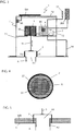
- FIG. 1 and 2 show water drainage systems 1 according to the invention, installed on a gravel roof and a green roof.
- gravel roof K is on the roof surface U which is also the water contact surface, applied a gravel pack k.
- a drain A through which water draining from the roof is supplied to the sewage system and which has a substantially circular inlet opening A1 lying in the plane of the water contact surface U, a shaft 7 is arranged, which encloses a cavity 71 and with a removable cover 70 is closed.
- the side walls of the shaft 7 have in the cross-sectional view not visible passage openings through which water can reach the interior 71 of the shaft 7.
- the shaft surrounded by the gravel corresponds in height to the height of the gravel pile k.
- the cover 70 is not covered with gravel and thus easily removable, whereby the cavity 71 of the shaft 7 is accessible.
- the water drainage system 1 according to the invention is arranged. This will be explained later.
- FIG. 2 Shown again is a cross section of a roof D in the region of a roof drain A. To protect the roof surface, some protective coverings SB are first applied to the roof surface U.
- a shaft 7 is set up with a water drainage system 1 according to the invention.
- the shaft 7 is connected watertight to the roof surface.
- the roof greening that surrounds the shaft is one with a permanent water reservoir WS. This is a cavity that can be filled with water and extends substantially over the entire roof area. This cavity is defined by pallet-like plastic hollow components, which are designed in a conventional manner over a large area on the roof surface.
- a drainage layer DS is applied, which is covered by a filter layer FS, which is to prevent the penetration of plant substrate PS in drainage layer and water storage. Perennials and shrubs are planted in the plant substrate. The water that serves to supply them is sucked upwards by capillary forces through the drainage layer out of the water reservoir and absorbed by the roots of the plants.
- the wall structure of the shaft 7 is such that the lower side wall 72 has no through-holes up to a height which substantially corresponds to the height of the water reservoir WS, so that water is dammed up to this height. At a height which substantially corresponds to the height of the drainage layer DS, the side wall 72 has a passage opening through which water can enter the interior 71 of the shaft.
- the upper part of the side wall, adjacent to the plant substrate PS, is in turn free of passage openings. This construction ensures that water can accumulate at the level of the water reservoir WS, however, an exceeding, unwanted increase in the amount of water in the green roofs on the drainage layer DS enter the interior of the shaft 7 and can be derived from there through the outflow A. , The closed upper part of the side wall 72 prevents the penetration of planting substrate into the shaft 7.
- the water reservoir WS is always sufficiently filled with water, on the other hand, but no waterlogging arises.
- the regulation of the water balance takes place with the aid of the water drainage system 1 according to the invention. This also makes it possible to regulate the water balance in a forward-looking manner, that is, for example, to drain water in advance from the water reservoir and from the roof surface U, if heavy rainfall is to be expected, which would exceed the storage capacity of an already at least partially filled water reservoir. This will be explained below with reference to FIGS. 1 to 3 be explained in more detail.
- the water drainage system 1 is in each case arranged in a shaft 7, which is placed above an outflow A on the water contact surface U.
- a part of the components of the water drainage system is arranged on an intermediate floor 73, which is mounted inside the shaft above the maximum water level.
- an actuating device 3 which moves the closure body 2 up or down.
- it may include a motor 38 that drives a pinion, which in turn moves a rack 33 up and down.
- the raising and lowering of the closure body 2 for example, by means of a push or threaded rod, a cable 31 or the like could take place.
- the control of the actuator 3 by means of a control device 4.
- the control device 4 can be operated either by means of an operating element, not shown here, such as a keyboard or a touch screen to manually send commands to the actuator 3 and / or retrieve information, etc.
- the purpose required programs, data, etc. are stored in a memory 40 of the control unit.
- a particular advantage of the water drainage system according to the invention is that it can also be operated from a remote location.
- a mobile phone / smartphone 5 which functions both as a receiving device and as a transmitter of the water drainage system and is connected by means of a data cable 50 to the control device 4.
- the control device 4 By selecting the mobile phone 5, it is possible to contact the control device 4 and to transmit to these commands or read data and / or messages.
- error messages issued by the control device 4 are transmitted via the mobile telephone 5 to a mobile telephone or another receiver of a user, so that the latter or a service provider can respond to the error message.
- the repair can in turn be done by remote maintenance via the mobile phone 5 to the control device 4, so that only in the rarest cases, a service technician on site must make a repair or maintenance.
- the described embodiment of the water drainage system 1 also makes it possible, in particular, to actuate the actuating device 3 via the control device 4 and thus to move the closure body 2 by manual influence and thus regulate the water balance on the roof from another location.
- a weather app is installed on the mobile phone, with which specific weather data for the location can be transmitted to the mobile phone 5.
- These weather data received by means of the mobile telephone 5 are then transmitted via the data cable 50 to the control device 4 and evaluated there.
- precipitation values stored in the memory 40 are compared with the precipitation values transmitted by the weather app.
- the deposited precipitation values are assigned corresponding total volumes, which must be included in the expected amount of precipitation per time corresponding to the catchment area of the roof in the water tank of the roof. For example, a forecast rainfall of x liters per square meter over the forecast period is associated with a volume of water to be absorbed of y liters over that period.
- These stored values are determined and stored in advance in a manner known per se specifically for the roof structure. Further values stored in the memory can include the retention surface specific to the roof structure, the maximum accumulation volume, specific evaporation values, the maximum drainage volume per time, the given retention values, such as the allowable discharge fee, the predetermined drainage coefficient, the predetermined retention time, etc., if necessary, structural Values or other data required for the water balance include.
- a water level indicator 10 in the area of the water reservoir, which also transmits values to the memory 40 of the control device 4. From these stored values, the parameters which are required for an optimal water balance in the green roof can be calculated by comparison with the expected precipitation values delivered by the weather app. Specifically, by comparing these values, parameters are determined with which by deliberately raising or lowering the closure body 2 so much water is accumulated in or drained from the water storage that on the one hand there is always a sufficient amount to supply the planting and, on the other hand, if heavy rainfall is expected , as much storage space is cleared in the water tank that the then falling rain can be absorbed in the water tank, without it comes to exceeding the maximum allowable or desired water level.
- the control device 4 causes the actuator 3 to lower the closure body 2 and the inlet A1 of the outlet A. close to catch the forecast for the current week rain in the water reservoir WS. The stored precipitate is then during the dry season the plants are available.
- Temperature values supplied by a temperature sensor 11 connected to the control device 4 can serve to take into account the loss of water due to evaporation and possibly increased water requirements of the planting at high temperatures in the calculation of the necessary quantities of water.
- the actuator is promptly before the onset of precipitation, the closure body 2 as long and to raise so far that a quantity of water drains from the roof, which at least corresponds to the expected precipitation.
- a solar module SM is arranged on the cover 70, which is associated with a power storage in the form of a battery AK.
- a power storage in the form of a battery AK.
- the connection between battery and consumers is not shown here for the sake of clarity.
- FIG. 1 shows a closure body 2 in the form of a narrowing on the outflow A peg, which in its closed position, the in FIG. 1 is shown with its lower end inserted into the drain and thus closes the inlet opening A1. Depending on how far the closure body 2 is lifted upwards, it can release the inlet opening A1 completely or partially (releasing an annular gap).
- FIG. 2 shows an alternative embodiment of a closure body 2, whose diameter is greater than the diameter of the inlet opening A1, so that the closure body 2 in its closed position covers the inlet opening A1 and closes in this way.
- the closure body could for example be arranged in lateral guide rails and with a push rod or another suitable movement device, which is controlled in a similar manner as described above by the control device.
- the closure body in FIG. 3 differs from the closure bodies of the Figures 1 and 2 in that it is not a massive body, but a hollow body. Specifically, a hollow cylinder is used here as the closure body, which is arranged above the inlet opening A1 of the outlet A such that its side wall completely encloses the inlet opening.
- FIG. 4 shown which is a cross-sectional view along the line XX of FIG. 3 is.
- the region 22 covered by the closure body 2 and shown here transversely striped is so large that it more than covers the opening cross-section A1 of the outflow A.
- this type of closure body is also called arranged above the drain. In its closed position, as in FIG.
- the hollow cylindrical closure body 2 prevents the entry of water into the drain A as long as the water level does not exceed the height of the side wall of the hollow cylinder.
- the height of the side wall of the hollow cylinder 2 is chosen so that it corresponds to the maximum desired or permissible water level on the water contact surface. If the water level continues to rise above this level, water flows over the edge of the hollow cylinder 2 and from there through the drain A. In this way, an emergency overflow can be realized, which works even if the closure body can no longer be lifted by means of the actuating device 3, which is here connected to a transverse strut of the closure body 2, due to a defect.
- FIG. 5 shows an alternative arrangement of in connection with FIG. 3
- the closure body 2 is used in a roof structure with permanent water storage WS, which is an alternative to that of FIG. 2 represents.indurcultivated openings in the side wall of the shaft 7 are not present here.
- the height of the permanent water reservoir WS is set in a manner known per se by means of a pipe A2, which is inserted with a corresponding projection into the drain A.
- the inlet A1 into the drain A is thus above the water contact surface U. Water can enter the drain A only when the water level exceeds the supernatant height of the tube A2. Also in this case, however, the outflow of water can be prevented by the outflow A is closed with the closure body 2.
- FIGS. 6 to 8 describe a particularly preferred embodiment of a hollow body closure body 2.
- the arrangement above the outflow A basically corresponds to those associated with FIGS. 3 to 5 was discussed.
- the closure body 2 itself again essentially has a hollow cylindrical shape, in which case, however, the lower edge is folded over towards the interior of the hollow cylinder and forms a contact surface 21 substantially parallel to the water contact surface.
- the footprint 21 is provided over its entire surface with a layer 25 of an elastomeric plastic.
- the closure body 2 is arranged within an annular outer wall 6, which has slot-shaped passage openings 60 in its lower wall area towards the water contact area, through which water can pass into the interior.
- the openings 60 may be covered with a filter material to prevent dirt particles from entering the interior.
- the outer wall 6 serves for fastening parts of the actuating device for moving the closure body 2.
- a push rod 32 is guided, which is coupled to the drive means (for example, a motor) of the actuator 3 and can be moved in the direction of the double arrow up and down.
- a ring plate 37 is fixed, for example, between two screw nuts 36 which are screwed onto a thread at the lower end of the push rod.
- a pivot lever 30 is pivotally mounted on the annular plate 37.
- a fastening tab which projects upwards over the annular plate 37 is used.
- the pivot lever 30 has a curved shape. In about the middle, in the most prominent portion of the curvature, the pivot lever 30 has another hole through which a further bolt 35 is guided, which is attached to a fork-shaped holder 63.
- the fork bracket 63 is attached to one of the support struts 61.
- the outer end of the pivot lever 30 is also perforated, in the hole another pin 35 is inserted, and via this a second pivot lever 34 is pivotally connected to the pivot lever 30.
- pivot lever 34 By a perforation at its opposite end is the second pivot lever 34 movably attached to a fastening tab 24, which in turn is fixedly connected to the side wall 20 of the closure body 2.
- fastening tab 24 By a perforation at its opposite end is the second pivot lever 34 movably attached to a fastening tab 24, which in turn is fixedly connected to the side wall 20 of the closure body 2.
- pivot lever mechanisms On the two other support struts 61 pivot lever mechanisms are mounted in the same way.
- the lifting and lowering of the hollow cylinder closure body 2 is carried out by moving the push rod 32 up and down, which - driven by the control device 4 - is driven by the motor of the actuator. If the push rod 32, for example, pressed down, it follows the inner end of the pivot lever 30 which is mounted on the annular plate 37. The pivot lever 30 therefore pivots about the middle pin 35 which is supported on the fork bracket 63, and its outer end moves upward. As a result, the closure body 2, which is connected via the pivot lever 34 with the pivot lever 30, lifted upwards. When pulling the push rod 32, the pivoting operation is in the opposite direction, and the closure body 2 is lowered.
Landscapes
- Engineering & Computer Science (AREA)
- Architecture (AREA)
- Civil Engineering (AREA)
- Structural Engineering (AREA)
- Sewage (AREA)
Applications Claiming Priority (1)
| Application Number | Priority Date | Filing Date | Title |
|---|---|---|---|
| DE102016001187.4A DE102016001187A1 (de) | 2016-02-03 | 2016-02-03 | Wasserabflusssystem mit automatisch regelbarer Abflussmenge |
Publications (2)
| Publication Number | Publication Date |
|---|---|
| EP3202995A1 true EP3202995A1 (fr) | 2017-08-09 |
| EP3202995B1 EP3202995B1 (fr) | 2021-12-15 |
Family
ID=57144705
Family Applications (1)
| Application Number | Title | Priority Date | Filing Date |
|---|---|---|---|
| EP16002151.5A Active EP3202995B1 (fr) | 2016-02-03 | 2016-10-05 | Système d'évacuation d'eau à réglage automatique du débit |
Country Status (2)
| Country | Link |
|---|---|
| EP (1) | EP3202995B1 (fr) |
| DE (1) | DE102016001187A1 (fr) |
Cited By (7)
| Publication number | Priority date | Publication date | Assignee | Title |
|---|---|---|---|---|
| DE102019004445A1 (de) * | 2019-06-24 | 2020-12-24 | Optigrün international AG | Wasserbilanzsteuerungssystem und Verfahren zu dessen Betrieb |
| EP3974597A1 (fr) | 2020-09-28 | 2022-03-30 | Optigrün international AG | Système de montage de toit, dispositif de montage de toit et procédé de construction d'un dispositif de montage de toit |
| EP4211322B1 (fr) | 2020-09-07 | 2024-03-27 | Climagrün GmbH/Srl | Système de retenue, de stockage et de réutilisation d'eau, destiné aux toits |
| WO2024168371A1 (fr) | 2023-02-17 | 2024-08-22 | Johann Trummer | Dispositif et procédé de commande du niveau d'eau sur un toit plat |
| EP4624693A1 (fr) | 2024-03-28 | 2025-10-01 | Optigrün international AG | Konlotschacht für ein dach mit wasserführender schicht et dachaufbau mit kontrelschacht |
| EP4624682A1 (fr) | 2024-03-28 | 2025-10-01 | Optigrün international AG | Système de gestion de précipitations |
| EP4623671A1 (fr) | 2024-03-28 | 2025-10-01 | Optigrün international AG | Système et procédé de gestion de précipitations |
Families Citing this family (3)
| Publication number | Priority date | Publication date | Assignee | Title |
|---|---|---|---|---|
| CN113006243B (zh) * | 2021-01-27 | 2022-11-25 | 广东智铭设计有限公司 | 一种市政排水用的雨水井 |
| CN113293845B (zh) * | 2021-07-06 | 2022-08-16 | 郑州市交通规划勘察设计研究院 | 道路施工排水系统 |
| CN115928779B (zh) * | 2022-12-30 | 2025-10-21 | 福建嘉宜建筑工程有限公司 | 一种房建施工工地排水系统 |
Citations (3)
| Publication number | Priority date | Publication date | Assignee | Title |
|---|---|---|---|---|
| NL7216175A (fr) * | 1971-12-14 | 1973-06-18 | ||
| DE19852561C1 (de) | 1998-11-13 | 2000-07-06 | Harzmann Optima Marketing Und | Wasserabflußsystem für Dachflächen |
| US20150218785A1 (en) * | 2013-12-20 | 2015-08-06 | Rainbank, Inc. | Automated roof runoff management system |
-
2016
- 2016-02-03 DE DE102016001187.4A patent/DE102016001187A1/de not_active Withdrawn
- 2016-10-05 EP EP16002151.5A patent/EP3202995B1/fr active Active
Patent Citations (3)
| Publication number | Priority date | Publication date | Assignee | Title |
|---|---|---|---|---|
| NL7216175A (fr) * | 1971-12-14 | 1973-06-18 | ||
| DE19852561C1 (de) | 1998-11-13 | 2000-07-06 | Harzmann Optima Marketing Und | Wasserabflußsystem für Dachflächen |
| US20150218785A1 (en) * | 2013-12-20 | 2015-08-06 | Rainbank, Inc. | Automated roof runoff management system |
Cited By (12)
| Publication number | Priority date | Publication date | Assignee | Title |
|---|---|---|---|---|
| DE102019004445A1 (de) * | 2019-06-24 | 2020-12-24 | Optigrün international AG | Wasserbilanzsteuerungssystem und Verfahren zu dessen Betrieb |
| EP3757300A1 (fr) | 2019-06-24 | 2020-12-30 | Optigrün international AG | Système de commande du bilan hydrique et son procédé de fonctionnement |
| EP4211322B1 (fr) | 2020-09-07 | 2024-03-27 | Climagrün GmbH/Srl | Système de retenue, de stockage et de réutilisation d'eau, destiné aux toits |
| EP3974597A1 (fr) | 2020-09-28 | 2022-03-30 | Optigrün international AG | Système de montage de toit, dispositif de montage de toit et procédé de construction d'un dispositif de montage de toit |
| DE102020005908A1 (de) | 2020-09-28 | 2022-03-31 | Optigrün international AG | Dachaufständerungssystem, dachaufständerung und verfahren zum aufbau einer dachaufständerung |
| WO2024168371A1 (fr) | 2023-02-17 | 2024-08-22 | Johann Trummer | Dispositif et procédé de commande du niveau d'eau sur un toit plat |
| EP4624693A1 (fr) | 2024-03-28 | 2025-10-01 | Optigrün international AG | Konlotschacht für ein dach mit wasserführender schicht et dachaufbau mit kontrelschacht |
| EP4624682A1 (fr) | 2024-03-28 | 2025-10-01 | Optigrün international AG | Système de gestion de précipitations |
| EP4623671A1 (fr) | 2024-03-28 | 2025-10-01 | Optigrün international AG | Système et procédé de gestion de précipitations |
| DE102024108978A1 (de) * | 2024-03-28 | 2025-10-02 | Optigrün international AG | Niederschlagsmanagement-system |
| DE102024108980A1 (de) * | 2024-03-28 | 2025-10-02 | Optigrün international AG | Niederschlagsmanagement-system und -verfahren |
| DE102024108979A1 (de) * | 2024-03-28 | 2025-10-02 | Optigrün international AG | Kontrollschacht für ein dach mit wasserführender schicht und dachaufbau mit kontrollschacht |
Also Published As
| Publication number | Publication date |
|---|---|
| DE102016001187A1 (de) | 2017-08-03 |
| EP3202995B1 (fr) | 2021-12-15 |
Similar Documents
| Publication | Publication Date | Title |
|---|---|---|
| EP3202995B1 (fr) | Système d'évacuation d'eau à réglage automatique du débit | |
| EP2982810B1 (fr) | Systeme d'evacuation d'eau a reglage automatique du debit | |
| EP3757300B1 (fr) | Système de commande du bilan hydrique et son procédé de fonctionnement | |
| EP2085527B1 (fr) | Installation d'exploitation d'eau de pluie | |
| DE102007030305B4 (de) | Wasserbewirtschaftungssystem für urbane und/oder landwirtschaftlich genutzte Flächen und Verfahren zu seiner Bereitstellung | |
| WO2022053667A1 (fr) | Dispositif d'irrigation et de drainage et/ou dispositif de stockage d'eau, de préférence pour la gestion de l'eau, en particulier pour l'irrigation d'espaces (verts) et/ou de plantes | |
| DE102017114887B4 (de) | Gebäudeflächen-Pflanzsystem und Kulturtopf für Pflanzen | |
| DE19852561C1 (de) | Wasserabflußsystem für Dachflächen | |
| US10053829B2 (en) | Flashboard riser system and method for water management | |
| DE10330318B4 (de) | Abflussverzögerndes Speicherelement und Drainagevorrichtung für Gründächer | |
| DE3418813A1 (de) | Entwaesserungssystem | |
| EP4706380A2 (fr) | Puits pour la régulation de l'eau souterraine | |
| DE19655159C2 (de) | Bodenfilter für Regen- und Abwasser mit Dichtbahn | |
| DE19610743C2 (de) | Bodenfilter für Regen- und Abwasser | |
| AT524209A4 (de) | System zur versickerung von niederschlagswasser | |
| EP4506518A1 (fr) | Dispositif d'évacuation d'eau de surface | |
| DE19700985A1 (de) | Versickerungseinrichtung | |
| AT527001B1 (de) | Vorrichtung und Verfahren zur Steuerung eines Wasserpegels auf einem Flachdach | |
| DE202025105906U1 (de) | Fassadenanordnung, und Bausatz zur Herstellung einer Fassadenanordnung | |
| DE102021128859A1 (de) | Regenwasserspeicher zum zwischenspeichern von regenwasser sowie dessen verwendung zur vermeidung von überlastungen von kanalisation und gewässern in folge eines starkregenereignisses | |
| EP4623671A1 (fr) | Système et procédé de gestion de précipitations | |
| DE19830192B4 (de) | Wasserbauwerk und Verfahren zur Wasserentlastung einer Abwasseranlage | |
| EP4624682A1 (fr) | Système de gestion de précipitations | |
| DE202024102417U1 (de) | Filteranordnung | |
| DE29807337U1 (de) | Abflußmengenregelvorrichtung für Regenrückhaltebecken |
Legal Events
| Date | Code | Title | Description |
|---|---|---|---|
| PUAI | Public reference made under article 153(3) epc to a published international application that has entered the european phase |
Free format text: ORIGINAL CODE: 0009012 |
|
| STAA | Information on the status of an ep patent application or granted ep patent |
Free format text: STATUS: THE APPLICATION HAS BEEN PUBLISHED |
|
| STAA | Information on the status of an ep patent application or granted ep patent |
Free format text: STATUS: REQUEST FOR EXAMINATION WAS MADE |
|
| AK | Designated contracting states |
Kind code of ref document: A1 Designated state(s): AL AT BE BG CH CY CZ DE DK EE ES FI FR GB GR HR HU IE IS IT LI LT LU LV MC MK MT NL NO PL PT RO RS SE SI SK SM TR |
|
| AX | Request for extension of the european patent |
Extension state: BA ME |
|
| 17P | Request for examination filed |
Effective date: 20170718 |
|
| RBV | Designated contracting states (corrected) |
Designated state(s): AL AT BE BG CH CY CZ DE DK EE ES FI FR GB GR HR HU IE IS IT LI LT LU LV MC MK MT NL NO PL PT RO RS SE SI SK SM TR |
|
| STAA | Information on the status of an ep patent application or granted ep patent |
Free format text: STATUS: EXAMINATION IS IN PROGRESS |
|
| 17Q | First examination report despatched |
Effective date: 20200930 |
|
| GRAP | Despatch of communication of intention to grant a patent |
Free format text: ORIGINAL CODE: EPIDOSNIGR1 |
|
| STAA | Information on the status of an ep patent application or granted ep patent |
Free format text: STATUS: GRANT OF PATENT IS INTENDED |
|
| INTG | Intention to grant announced |
Effective date: 20210831 |
|
| GRAS | Grant fee paid |
Free format text: ORIGINAL CODE: EPIDOSNIGR3 |
|
| GRAA | (expected) grant |
Free format text: ORIGINAL CODE: 0009210 |
|
| STAA | Information on the status of an ep patent application or granted ep patent |
Free format text: STATUS: THE PATENT HAS BEEN GRANTED |
|
| AK | Designated contracting states |
Kind code of ref document: B1 Designated state(s): AL AT BE BG CH CY CZ DE DK EE ES FI FR GB GR HR HU IE IS IT LI LT LU LV MC MK MT NL NO PL PT RO RS SE SI SK SM TR |
|
| REG | Reference to a national code |
Ref country code: GB Ref legal event code: FG4D Free format text: NOT ENGLISH Ref country code: CH Ref legal event code: EP |
|
| REG | Reference to a national code |
Ref country code: IE Ref legal event code: FG4D Free format text: LANGUAGE OF EP DOCUMENT: GERMAN Ref country code: DE Ref legal event code: R096 Ref document number: 502016014260 Country of ref document: DE |
|
| REG | Reference to a national code |
Ref country code: AT Ref legal event code: REF Ref document number: 1455608 Country of ref document: AT Kind code of ref document: T Effective date: 20220115 |
|
| REG | Reference to a national code |
Ref country code: NL Ref legal event code: FP |
|
| REG | Reference to a national code |
Ref country code: LT Ref legal event code: MG9D |
|
| PG25 | Lapsed in a contracting state [announced via postgrant information from national office to epo] |
Ref country code: RS Free format text: LAPSE BECAUSE OF FAILURE TO SUBMIT A TRANSLATION OF THE DESCRIPTION OR TO PAY THE FEE WITHIN THE PRESCRIBED TIME-LIMIT Effective date: 20211215 Ref country code: LT Free format text: LAPSE BECAUSE OF FAILURE TO SUBMIT A TRANSLATION OF THE DESCRIPTION OR TO PAY THE FEE WITHIN THE PRESCRIBED TIME-LIMIT Effective date: 20211215 Ref country code: FI Free format text: LAPSE BECAUSE OF FAILURE TO SUBMIT A TRANSLATION OF THE DESCRIPTION OR TO PAY THE FEE WITHIN THE PRESCRIBED TIME-LIMIT Effective date: 20211215 Ref country code: BG Free format text: LAPSE BECAUSE OF FAILURE TO SUBMIT A TRANSLATION OF THE DESCRIPTION OR TO PAY THE FEE WITHIN THE PRESCRIBED TIME-LIMIT Effective date: 20220315 |
|
| PG25 | Lapsed in a contracting state [announced via postgrant information from national office to epo] |
Ref country code: SE Free format text: LAPSE BECAUSE OF FAILURE TO SUBMIT A TRANSLATION OF THE DESCRIPTION OR TO PAY THE FEE WITHIN THE PRESCRIBED TIME-LIMIT Effective date: 20211215 Ref country code: NO Free format text: LAPSE BECAUSE OF FAILURE TO SUBMIT A TRANSLATION OF THE DESCRIPTION OR TO PAY THE FEE WITHIN THE PRESCRIBED TIME-LIMIT Effective date: 20220315 Ref country code: LV Free format text: LAPSE BECAUSE OF FAILURE TO SUBMIT A TRANSLATION OF THE DESCRIPTION OR TO PAY THE FEE WITHIN THE PRESCRIBED TIME-LIMIT Effective date: 20211215 Ref country code: HR Free format text: LAPSE BECAUSE OF FAILURE TO SUBMIT A TRANSLATION OF THE DESCRIPTION OR TO PAY THE FEE WITHIN THE PRESCRIBED TIME-LIMIT Effective date: 20211215 Ref country code: GR Free format text: LAPSE BECAUSE OF FAILURE TO SUBMIT A TRANSLATION OF THE DESCRIPTION OR TO PAY THE FEE WITHIN THE PRESCRIBED TIME-LIMIT Effective date: 20220316 |
|
| PG25 | Lapsed in a contracting state [announced via postgrant information from national office to epo] |
Ref country code: SM Free format text: LAPSE BECAUSE OF FAILURE TO SUBMIT A TRANSLATION OF THE DESCRIPTION OR TO PAY THE FEE WITHIN THE PRESCRIBED TIME-LIMIT Effective date: 20211215 Ref country code: SK Free format text: LAPSE BECAUSE OF FAILURE TO SUBMIT A TRANSLATION OF THE DESCRIPTION OR TO PAY THE FEE WITHIN THE PRESCRIBED TIME-LIMIT Effective date: 20211215 Ref country code: RO Free format text: LAPSE BECAUSE OF FAILURE TO SUBMIT A TRANSLATION OF THE DESCRIPTION OR TO PAY THE FEE WITHIN THE PRESCRIBED TIME-LIMIT Effective date: 20211215 Ref country code: PT Free format text: LAPSE BECAUSE OF FAILURE TO SUBMIT A TRANSLATION OF THE DESCRIPTION OR TO PAY THE FEE WITHIN THE PRESCRIBED TIME-LIMIT Effective date: 20220418 Ref country code: ES Free format text: LAPSE BECAUSE OF FAILURE TO SUBMIT A TRANSLATION OF THE DESCRIPTION OR TO PAY THE FEE WITHIN THE PRESCRIBED TIME-LIMIT Effective date: 20211215 Ref country code: EE Free format text: LAPSE BECAUSE OF FAILURE TO SUBMIT A TRANSLATION OF THE DESCRIPTION OR TO PAY THE FEE WITHIN THE PRESCRIBED TIME-LIMIT Effective date: 20211215 Ref country code: CZ Free format text: LAPSE BECAUSE OF FAILURE TO SUBMIT A TRANSLATION OF THE DESCRIPTION OR TO PAY THE FEE WITHIN THE PRESCRIBED TIME-LIMIT Effective date: 20211215 |
|
| PG25 | Lapsed in a contracting state [announced via postgrant information from national office to epo] |
Ref country code: PL Free format text: LAPSE BECAUSE OF FAILURE TO SUBMIT A TRANSLATION OF THE DESCRIPTION OR TO PAY THE FEE WITHIN THE PRESCRIBED TIME-LIMIT Effective date: 20211215 |
|
| REG | Reference to a national code |
Ref country code: DE Ref legal event code: R097 Ref document number: 502016014260 Country of ref document: DE |
|
| PG25 | Lapsed in a contracting state [announced via postgrant information from national office to epo] |
Ref country code: IS Free format text: LAPSE BECAUSE OF FAILURE TO SUBMIT A TRANSLATION OF THE DESCRIPTION OR TO PAY THE FEE WITHIN THE PRESCRIBED TIME-LIMIT Effective date: 20220415 |
|
| PLBE | No opposition filed within time limit |
Free format text: ORIGINAL CODE: 0009261 |
|
| STAA | Information on the status of an ep patent application or granted ep patent |
Free format text: STATUS: NO OPPOSITION FILED WITHIN TIME LIMIT |
|
| PG25 | Lapsed in a contracting state [announced via postgrant information from national office to epo] |
Ref country code: DK Free format text: LAPSE BECAUSE OF FAILURE TO SUBMIT A TRANSLATION OF THE DESCRIPTION OR TO PAY THE FEE WITHIN THE PRESCRIBED TIME-LIMIT Effective date: 20211215 Ref country code: AL Free format text: LAPSE BECAUSE OF FAILURE TO SUBMIT A TRANSLATION OF THE DESCRIPTION OR TO PAY THE FEE WITHIN THE PRESCRIBED TIME-LIMIT Effective date: 20211215 |
|
| 26N | No opposition filed |
Effective date: 20220916 |
|
| PG25 | Lapsed in a contracting state [announced via postgrant information from national office to epo] |
Ref country code: SI Free format text: LAPSE BECAUSE OF FAILURE TO SUBMIT A TRANSLATION OF THE DESCRIPTION OR TO PAY THE FEE WITHIN THE PRESCRIBED TIME-LIMIT Effective date: 20211215 |
|
| PG25 | Lapsed in a contracting state [announced via postgrant information from national office to epo] |
Ref country code: MC Free format text: LAPSE BECAUSE OF FAILURE TO SUBMIT A TRANSLATION OF THE DESCRIPTION OR TO PAY THE FEE WITHIN THE PRESCRIBED TIME-LIMIT Effective date: 20211215 Ref country code: IT Free format text: LAPSE BECAUSE OF FAILURE TO SUBMIT A TRANSLATION OF THE DESCRIPTION OR TO PAY THE FEE WITHIN THE PRESCRIBED TIME-LIMIT Effective date: 20211215 |
|
| P01 | Opt-out of the competence of the unified patent court (upc) registered |
Effective date: 20230515 |
|
| PG25 | Lapsed in a contracting state [announced via postgrant information from national office to epo] |
Ref country code: LU Free format text: LAPSE BECAUSE OF NON-PAYMENT OF DUE FEES Effective date: 20221005 |
|
| REG | Reference to a national code |
Ref country code: DE Ref legal event code: R082 Ref document number: 502016014260 Country of ref document: DE Representative=s name: MAIWALD GMBH, DE |
|
| PG25 | Lapsed in a contracting state [announced via postgrant information from national office to epo] |
Ref country code: IE Free format text: LAPSE BECAUSE OF NON-PAYMENT OF DUE FEES Effective date: 20221005 |
|
| PG25 | Lapsed in a contracting state [announced via postgrant information from national office to epo] |
Ref country code: HU Free format text: LAPSE BECAUSE OF FAILURE TO SUBMIT A TRANSLATION OF THE DESCRIPTION OR TO PAY THE FEE WITHIN THE PRESCRIBED TIME-LIMIT; INVALID AB INITIO Effective date: 20161005 |
|
| PG25 | Lapsed in a contracting state [announced via postgrant information from national office to epo] |
Ref country code: CY Free format text: LAPSE BECAUSE OF FAILURE TO SUBMIT A TRANSLATION OF THE DESCRIPTION OR TO PAY THE FEE WITHIN THE PRESCRIBED TIME-LIMIT Effective date: 20211215 |
|
| PG25 | Lapsed in a contracting state [announced via postgrant information from national office to epo] |
Ref country code: MK Free format text: LAPSE BECAUSE OF FAILURE TO SUBMIT A TRANSLATION OF THE DESCRIPTION OR TO PAY THE FEE WITHIN THE PRESCRIBED TIME-LIMIT Effective date: 20211215 |
|
| PG25 | Lapsed in a contracting state [announced via postgrant information from national office to epo] |
Ref country code: TR Free format text: LAPSE BECAUSE OF FAILURE TO SUBMIT A TRANSLATION OF THE DESCRIPTION OR TO PAY THE FEE WITHIN THE PRESCRIBED TIME-LIMIT Effective date: 20211215 |
|
| PG25 | Lapsed in a contracting state [announced via postgrant information from national office to epo] |
Ref country code: MT Free format text: LAPSE BECAUSE OF FAILURE TO SUBMIT A TRANSLATION OF THE DESCRIPTION OR TO PAY THE FEE WITHIN THE PRESCRIBED TIME-LIMIT Effective date: 20211215 |
|
| REG | Reference to a national code |
Ref country code: CH Ref legal event code: U11 Free format text: ST27 STATUS EVENT CODE: U-0-0-U10-U11 (AS PROVIDED BY THE NATIONAL OFFICE) Effective date: 20251101 |
|
| PGFP | Annual fee paid to national office [announced via postgrant information from national office to epo] |
Ref country code: NL Payment date: 20251023 Year of fee payment: 10 |
|
| PGFP | Annual fee paid to national office [announced via postgrant information from national office to epo] |
Ref country code: DE Payment date: 20251029 Year of fee payment: 10 |
|
| PGFP | Annual fee paid to national office [announced via postgrant information from national office to epo] |
Ref country code: GB Payment date: 20251024 Year of fee payment: 10 |
|
| PGFP | Annual fee paid to national office [announced via postgrant information from national office to epo] |
Ref country code: AT Payment date: 20251021 Year of fee payment: 10 |
|
| PGFP | Annual fee paid to national office [announced via postgrant information from national office to epo] |
Ref country code: FR Payment date: 20251029 Year of fee payment: 10 |
|
| PGFP | Annual fee paid to national office [announced via postgrant information from national office to epo] |
Ref country code: BE Payment date: 20251022 Year of fee payment: 10 |
|
| PGFP | Annual fee paid to national office [announced via postgrant information from national office to epo] |
Ref country code: CH Payment date: 20251101 Year of fee payment: 10 |