EP3202995B1 - Système d'évacuation d'eau à réglage automatique du débit - Google Patents
Système d'évacuation d'eau à réglage automatique du débit Download PDFInfo
- Publication number
- EP3202995B1 EP3202995B1 EP16002151.5A EP16002151A EP3202995B1 EP 3202995 B1 EP3202995 B1 EP 3202995B1 EP 16002151 A EP16002151 A EP 16002151A EP 3202995 B1 EP3202995 B1 EP 3202995B1
- Authority
- EP
- European Patent Office
- Prior art keywords
- water
- drain
- contact surface
- actuator
- closing body
- Prior art date
- Legal status (The legal status is an assumption and is not a legal conclusion. Google has not performed a legal analysis and makes no representation as to the accuracy of the status listed.)
- Active
Links
Images


Classifications
-
- E—FIXED CONSTRUCTIONS
- E04—BUILDING
- E04D—ROOF COVERINGS; SKY-LIGHTS; GUTTERS; ROOF-WORKING TOOLS
- E04D13/00—Special arrangements or devices in connection with roof coverings; Protection against birds; Roof drainage ; Sky-lights
- E04D13/04—Roof drainage; Drainage fittings in flat roofs, balconies or the like
- E04D13/0404—Drainage on the roof surface
- E04D13/0409—Drainage outlets, e.g. gullies
- E04D2013/0427—Drainage outlets, e.g. gullies with means for controlling the flow in the outlet
Definitions
- the invention relates to a method for regulating the water level on the surface of a green roof and a water drainage system for carrying out the method, in particular such a system which prevents rainwater that falls on a surface from flowing off in an essentially unreduced amount and without a time delay.
- the valve is closed when a rain detector or the weather data report heavy rain, in order to prevent the rainwater from immediately draining off the roof in the event of heavy rain.
- the rainwater is left to stand for a while on the roof surface and, after a specified period of time, is completely drained from the roof into the sewer system.
- rainwater is released from green roofs with a time lag.
- the reason for this is that the plants and the substrate on which the plants are planted store rainwater and only release it after a delay.
- the amount of water released is lower, as part of the amount of precipitation evaporates through the surface of the ground and another part is consumed by the plants.
- green roofs Compared to conventional, non-planted roofs, green roofs have the advantage that the precipitation that has fallen on them is released into the sewer system in a reduced amount and with a time delay.
- the structure of the plant substrate for the green roof differs depending on the type of plants that are to be planted on the roof. Both single-layer and multilayer structures are known. Usually, the more demanding the plants become, the greater the number of layers. If, for example, perennials, shrubs or trees are to be planted, multilayer structures are usually required, and backwater irrigation is necessary in order to provide the plants with sufficient water.
- a layer structure for such an intensive green roof thus comprises a water reservoir from which the plants can be continuously supplied with moisture.
- the water reservoir enables the uptake and retention of larger amounts of water.
- the runoff coefficients specified by the authorities i.e. the permissible runoff amount of water per time
- the water drainage system described there has concentric pipes opening into a roof drain, which can be adjusted in relation to one another in such a way that the amount of water running off is limited.
- the flow rate is predefined, among other things, depending on the size of the area to be drained, the type of roof structure and the amount of precipitation to be expected.
- the runoff coefficient C is based on a heavy precipitation event of 300 liters per second and hectare for a duration of 15 minutes. This corresponds to the amount of 27 liters per square meter. 27 liters correspond to the (currently) valid standards and precipitation data the so-called Kostra Atlas (statistical precipitation events, based on data from the German Weather Service (DWD)) in most cities and municipalities, a precipitation event that occurs once a century or at least once every 50 years, depending on the region.
- Kostra Atlas statistical precipitation events, based on data from the German Weather Service (DWD) in most cities and municipalities, a precipitation event that occurs once a century or at least once every 50 years, depending on the region.
- the green roof systems currently on the market have not yet been able to meet the increased requirements. In particular, the greatly extended retention times are usually not achieved. The reason for this is, among other things, that today's systems are usually designed to meet the discharge coefficient C - i.e. only ensure the specified water drainage for the prescribed period of 15 minutes or a little longer. After this period, however, the specified amount of water may then be exceeded again, that is, the amount of water fed into the sewer system increases again. If precipitation continues to fall, the green roof gradually soaks up like a sponge, and when it is completely saturated, the runoff coefficient rises to 1, which means that any further precipitation runs off the roof unhindered and completely.
- the object of the invention is accordingly to specify a method and a water drainage system which meet these requirements, ensure a high level of water retention even in the case of prolonged heavy rain events and ensure a flexible water balance.
- the invention relates in one aspect to a water drainage system according to claim 11 for carrying out the method according to the invention, and the method according to the invention according to claim 1 uses a water drainage system for a water contact surface having a drain, which is a roof surface of a green roof, comprising a closure body which is inside or is arranged above the drain and designed to prevent the entry of water into the drain, an actuating device with which the closure body can be moved in order to allow the entry of water into the drain, and a control device for controlling the actuating device, which is formed is to control the actuating device as a function of evaluated weather data.
- the water drainage system makes it possible, by means of a control device and actuating device, to use the closure body for watertight closure of the drain individually and as required.
- the closure body can be moved by means of the actuating device from a first position preventing water from entering the drain into a second position in which water can enter the drain.
- the present invention now also enables the amount of drainage not only to be determined according to the respective circumstances adapt, but also change over time.
- the flow rate is set on the basis of evaluated weather data.
- the drain can be reduced or completely closed in order to prevent the water reservoir on the water contact area from being completely emptied and, for example, insufficient irrigation for a green roof on the water contact area.
- the invention not only allows individual planning and setting of the water storage amount on the water contact surface and the amount drained per time, but also enables an individual, targeted and continuous adjustment of the water balance over the entire operating time.
- the closure body can be designed in such a way that it can be moved between a position that completely closes the drain and a position that completely releases the drain.
- the controllability of the movement of the closure body and thus the flow rate per time also allows an adjustment practically in real time from an external location and therefore with significantly less effort than before.
- the controllability in real time also enables a very quick reaction to new environmental conditions such as extreme rainfall, a major advantage of the invention is the ability to make predictive settings over the operating time of the water drainage system.
- the control device is designed in such a way that it controls the actuation device as a function of evaluated weather data, including externally received and evaluated weather forecast data, including forecast amounts of precipitation.
- weather data are expediently used which relate to the respective location at which the water drainage system according to the invention is located.
- Such weather data are available from various providers, for example in the form of so-called weather apps, which can be called up specifically for a specific predetermined location.
- This weather data can either be transmitted via cable or, what is preferred, wirelessly to the water drainage system. It is particularly preferred to transmit the weather data by mobile radio.
- the receiving device provided for receiving the weather data in the water drainage system is then a mobile radio device, in particular a smartphone, in this case.
- a tablet PC or any other suitable receiving device.
- This is arranged at a suitable location in the water drainage system and connected to the control device so that the weather data received by the receiving device can be transmitted to the control device.
- the data is preferably transmitted here by means of a cable, but wireless transmission options are also conceivable, for example a Bluetooth connection.
- the control is preferably carried out not only on the basis of the weather data for the current day, but also taking into account the weather forecast data for at least the following day, preferably for several days in advance. In this way it is possible to make preparations for expected heavy rain events or longer dry periods. For example, it is possible to calculate the storage requirements for the precipitation to be expected for the following days. In order to be able to absorb this expected volume of precipitation, storage space on the water contact surface can be cleared, if necessary, in order to create space for the new precipitation.
- the control of the water drainage system takes place in such a way that the actuating device opens the closure body for a calculated period of time and releases the drain so that as much water runs off the water contact surface as corresponds to the volume of the new precipitation to be expected.
- a safety margin can also be planned in order to ensure sufficient storage volume even if the precipitation is actually greater than announced. If weather forecast data for several days in advance are taken into account, the stored water can be drained from the water contact area in good time so that the permitted flow rate is not exceeded during the draining of the water to clear storage volumes before the expected heavy rain event occurs.
- the control device After the required amount of water has been drained from the water contact surface (the calculated opening period for the drain has expired), the control device transmits a control signal to the actuating device, whereupon the actuating device reduces or completely closes the drain by moving the closure body, so that the forecast heavy rain, as soon as it begins to fall, it is collected and is not diverted from the water contact surface into the sewerage system, or only with the permitted delay.
- an irrigation system can be provided which can also be controlled by the control device. This is put into operation by the control device when the water stored on the drainage surface is no longer sufficient to irrigate a green roof.
- a water level indicator can be provided to determine the stored amount of water, which either continuously transmits measured values to the control device or forwards a warning if the water level falls below a predetermined value.
- the control device activates the irrigation device in order to ensure an adequate supply of water to the plants.
- the water level indicator can also be used regardless of its presence an irrigation device can advantageously be used to determine the water level on the water contact surface, so for example also in the case described above to determine the available free storage volume in preparation for rainfall.
- the information and data required for calculating the control processes are preferably stored in the control device, which has a suitable memory for this purpose.
- Necessary data are, in particular, the data already used from the state of the art for the design of green roofs or gravel roofs with water retention, such as in particular data for calculating the maximum storage volume, the permissible runoff quantities, the retention capacity, etc. Drainage donation required by the authorities (e.g. permitted runoff quantities in liters / second.
- the water contact area (the area that can be used as a retention area), the so-called catchment areas (surrounding areas from which water hits the water contact area can reach), the precipitation to be expected for the respective location (usually the precipitation parameters specified by the authorities in accordance with the DIN standard or Kostra Atlas for the measurement frequency of extreme weather events), the emptying time (period within which the calculated amounts of precipitation water flow away from the retention areas d ürfen), the accumulation height (results in the absorbable water volume with the size of the retention area), the number of drains in the water drainage area and the drainage cross-section.
- each of these drains is expediently provided with an automatically actuated closure body according to the invention in order to control the flow rate of each of these drains as a function of the evaluated weather data.
- the parameters mentioned can be used to calculate not only the maximum drainage cross-section but also the maximum opening cross-section of the drainage opening for each individual drainage of the water drainage system according to the invention.
- values for the calculated evaporation and, for example, structural values can be included in the calculation and stored in the memory. Based on these values, the maximum accumulation volume and the maximum flow rate per time from the water contact area can be calculated.
- volume losses for example due to evaporation, preferably depending on the outside temperature, can be taken into account.
- the basic design and basic settings of the water drainage system and their calculations correspond in principle to those of the state of the art.
- the corresponding inflow volumes for the respective catchment areas and water contact areas known for the location are determined by a weather app or other weather forecast forecast precipitation amounts calculated.
- predicted precipitation values which are specified in liters per square meter, for example, inflow volumes calculated in advance for the respective amounts of precipitation in a certain period of time are stored for the respective location in the memory of the control unit.
- These inflow volumes then in turn result in the storage volumes that have to be made available to accommodate the predicted amounts of precipitation.
- the amounts of water per time that have to be drained from the water contact surface in order to create space for the expected precipitation are then calculated.
- the control device actuates the actuating device, which in turn opens the drain completely or partially for the calculated period of time by moving the closure body in accordance with the calculated parameters in order to drain the calculated drain volume.
- the runoff is then completely or partially closed again (for example depending on the specified runoff coefficient) in order to be able to absorb the calculated precipitation volume.
- the calculations are calculated on the basis of values and calculation formulas previously stored in the control device, taking into account the externally transmitted weather data.
- the computer center of an operator can be used for the calculation, which calculates the required control parameters for the respective location and then transmits the control parameters to the control device of the water drainage system according to the invention in a wired or wireless manner.
- the wireless transmission can, as already described above, take place by means of mobile radio, for which purpose a mobile radio device is installed in the water drainage system.
- the water drainage system comprises not only a receiver, but also a transmitter for transmitting messages and / or data to an external receiver.
- This transmitter is preferably again a mobile radio device, expediently the same mobile radio device that is already used as the receiver of the weather data.
- the transmitter specifically the mobile radio device, can on the one hand serve to send measured values from the system to a to transfer to an external data center, where these measured values are used to carry out calculations in order to determine control data, which are then sent back to the mobile radio device of the water drainage system again via mobile radio.
- the transmitter can also be used to send status messages and, in particular, error messages to an external receiver.
- maintenance or repair of the water drainage system can be carried out very quickly.
- This maintenance or repair is particularly preferably carried out by remote maintenance, that is to say by external access to the control device and via this to the connected components, which considerably reduces the effort and the costs.
- the water drainage system according to the invention and the method according to the invention are designed for use on green roofs, hereinafter referred to as green roofs for short, on which a certain volume of water is to be retained for a certain period of time and / or fed to the sewer system with a time delay and in a controlled manner.
- the water contact area is a roof area that has a drain through which water is discharged into the sewer system.
- the water drainage system according to the invention corresponds to such water drainage systems as have already been used in the prior art, in particular those such as those shown in FIG DE 198 52 561 C1 are described.
- the water drainage system usually comprises a shaft, which surrounds a cavity with its side walls. This shaft is set up above the drain on the roof surface.
- the closure body, the actuating device with which it is moved, and preferably also the control device are expediently located within this shaft.
- the shaft can have through openings in its side walls directly above the water contact surface, which allow unhindered entry of water located on the water contact surface into the cavity of the shaft. If a certain water reservoir is to be permanently retained on the water contact surface, the through openings can also be located at a certain distance from the water contact surface in the side walls of the shaft, so that water can only enter the cavity when a certain water level is reached.
- the lower edge of the shaft should in this case be placed on the roof surface as watertight as possible self-adhesive butyl seals, compression tapes (elastic closed-cell foamed plastic tapes) and multi-component curable liquid plastic sealants or combinations thereof.
- the lower edge of the shaft can be issued in the form of a flange. The seal is then expediently attached to the side of the flange facing in the direction of the roof surface.
- the formation of a water reservoir on the water contact surface can also be achieved in that a pipe is located around or inserted into the drain, which protrudes over the water contact surface at a height that corresponds to the desired accumulation height of the water on the roof surface (cf. for example too DE 198 52 561 C1 ).
- the height depends, among other things, on the type of green roof or gravel fill chosen and is usually between 2 and 8 cm for green roofs.
- the maximum water absorption volume of the roof surface is calculated from the contact area of the water on the roof surface and the accumulation height - if necessary minus the volume of other structures.
- a closure body which prevents the entry of water into the drain when it is in its closed position within or above the Drain is arranged.
- it completely closes the inlet cross-section to the drain, either by being plugged into the drain itself and closing it, or by closing a pipe or other supply line that opens into the drain.
- the inlet opening of the pipe opening into the drain (or a corresponding supply line), its drain cross-section, etc., is also addressed as an alternative.
- the alternative with a pipe or supply line usually relates to systems in which a permanent water reservoir is kept on the water contact surface.
- the locking body automatically actuated according to the invention.
- arranged within the drain also includes a partial arrangement within the drain.
- it can be a plug, for example, which closes the inlet opening into the drain.
- the actuating device is designed accordingly to push the stopper into the inlet opening to close the drain and to lift it off from the inlet opening to open it.
- the stopper can also be partially lifted from the inlet opening, so that an annular gap with a smaller opening cross-section than the inlet opening as a whole results.
- a closure body arranged above the drain should be understood to mean a closure body which covers the inlet cross section of the drain and / or completely surrounds it without being inserted into the drain.
- it could be, for example, a cover that lies over the inlet cross-section of the drain.
- it could also be a hollow body arranged above the drain, the side walls of which are closed at least up to a certain height and thus prevent the entry of water into the drain.
- the inner surface of the hollow body enclosed by the side walls is located above the drain, that is, a cross section of the closure body covers the inlet cross section into the drain.
- the definition “above the outlet” therefore does not necessarily mean that the closure body is in any case completely above the inlet cross-section down the drain.
- the closure body expediently lies or stands on the water contact surface and prevents water from entering the drain from the sides.
- a closure body arranged above the drain can also be pulled down laterally around the pipe, for example down to the water contact surface. It is crucial, however, that the closure body extends upwards via the inlet opening of the pipe, which is also the inlet opening into the drain, and thus prevents the direct entry of water into the pipe and from there into the drain if the maximum possible accumulation height of the Water (according to the height of the pipe) is reached.
- the closure body can be designed like a pot, the bottom of the pot running above the inlet opening into the drain.
- the closure body it is also possible to design the closure body as a hollow body open at the top, for example as a hollow cylinder. In the closed position, the height of the walls of the hollow body protrudes above the inlet opening of the drain. Since the closure body is open at the top in this case, the closure body only acts as a closure for the drain until the water level on the water contact surface has reached the height of the walls of the hollow body. However, this is quite intentional, as certain roof structures can only cope with a maximum water level.
- NB The maximum water level is not the accumulation height of the permanent water storage tank, but a higher water level which, if exceeded, allows water to pass over the sealing on the building side and thus damage the building itself.
- a maximum water level could also be predetermined by the statics of the building.
- the closure body used according to the invention does not necessarily have to prevent the entry of water into the drain for all water levels on the water contact surface. In the context of the invention, it is rather sufficient if the closure body prevents water from reaching the drain unhindered for certain water levels. After a certain water level has been exceeded, it may even be desirable for the closure body to enable an emergency drain that prevents further accumulation of water on the water contact surface.
- the closure body is arranged around a water accumulation pipe or the like, it can be pushed directly onto the water accumulation pipe, as is basically already the case in FIG DE 19852561 C1 is described. However, it is preferred if the closure body is arranged at a lateral distance from the water accumulation pipe.
- the closure body is designed as a hollow body and in particular as a hollow cylinder which, in its closed position, rests with its lower edge on the water contact surface.
- the lower wall area is preferably folded over to the side in order to produce an enlarged contact surface. This support surface expediently runs essentially parallel to the water contact surface.
- the contact surface facing the water contact surface can be covered with an elastically deformable material.
- This can be, for example, a coating made of an elastomeric plastic or the sealing materials already described in connection with the contact surfaces of the shaft, such as sealing tapes, for example.
- the side wall of the hollow body is self-contained and free of openings, at least in its area facing the water contact surface.
- the height of the side wall corresponds to the desired maximum water level on the water contact surface.
- the side wall extends beyond the maximum water level, but above the latter has at least one inlet opening through which water can enter the interior of the hollow body when the maximum water level is exceeded.
- the actuating device is preferably designed in such a way that it can lift the closure body upwards from the inlet opening of the drain or move it to the side.
- the former is particularly preferred.
- the outflow speed can be influenced by how far the closure body is removed from the inlet opening and how large the gap is selected between the closure body and the inlet opening. The amount of outflow is controlled accordingly via the time for which the closure body releases the outflow.
- the actuation device with which the closure body is moved can in principle be designed in any suitable manner known from the prior art. Suitable components of the actuating device include, for example, a cable mechanism, a pivot lever, a push or pull rod and / or a toothed or threaded rod. Suitable combinations of several of these elements are of course also possible.
- the type of drive is also not restricted further. In principle, any suitable movement device can be used, for example an electric motor, an electromagnetic, hydraulic or pneumatic drive. The use of a pneumatic drive is preferred because of the low maintenance requirement in the humid and strong temperature fluctuations environment, which also has the advantage of an almost wear-free and loss-free power transmission.
- an outer wall arranged on the water contact surface is arranged laterally around the closure body.
- This outer wall which basically allows water to enter its interior and for this purpose has at least one passage opening, can serve, for example, to prevent or at least reduce the entry of contaminants.
- the at least one passage opening is expediently provided with a particle filter, for example in the form of a sieve, a filter mat or some other filter material.
- the outer wall serves to fasten parts of the actuating device for the closure body and / or guide elements which guide and facilitate the movement sequences of the closure body.
- the closure body is connected to at least one pivot lever which is pivotably mounted on a support strut, which in turn is attached to the outer wall which is arranged around the closure body.
- the pivoting of the pivoting lever and thus the raising and lowering of the closure body takes place by moving a push rod which acts on an arm of the pivoting lever.
- the actuating device - like the control device, the receiving device and an optionally present transmitting device, in particular in the form of a mobile radio device - is expediently arranged in the interior of a well located on the water contact surface.
- the upper end of the shaft remote from the roof surface forms a maintenance opening which enables access to the components of the water drainage system present in the cavity and thus their easy maintenance.
- This maintenance opening is expediently closed with a removable or hinged cover.
- This cover is preferably lockable, so that the components arranged in the shaft are protected not only from the effects of the weather, but also from access by unauthorized persons.
- a solar module with which the power-consuming components of the water drainage system can be supplied with power, can be provided on the cover or, alternatively, raised in the vicinity of the shaft.
- an electricity storage device for example in the form of a rechargeable battery, is also expediently provided. All components are particularly useful For example, actuating device, control device, receiving device and transmitter, supplied with solar power. In this way, a completely self-sufficient operation of the water drainage system is possible.
- FIGS 1 and 2 show water drainage systems 1, installed on a gravel roof and a green roof.
- gravel roof K shown is applied to the roof surface U, which is at the same time the water contact surface, a bed of gravel k.
- a shaft 7 is set up, which encloses a cavity 71 and has a removable cover 70 is locked.
- the side walls of the shaft 7 have through openings, which are not visible in the cross-sectional view, through which water can get into the interior 71 of the shaft 7.
- the shaft surrounded by the gravel corresponds in height to the height of the gravel fill k.
- the cover 70 is not covered with gravel and is therefore easily removable, so that the cavity 71 of the shaft 7 is accessible.
- the water drainage system 1 according to the invention is arranged in the interior of the shaft 7. This will be explained in more detail later.
- a green roof G Shown again is a cross section of a roof D in the area of a roof drain A. To protect the roof surface, some protective coverings SB are first applied to the roof surface U.
- a shaft 7 with a water drainage system 1 according to the invention is set up.
- the shaft 7 is connected to the roof surface in a watertight manner.
- the green roof surrounding the shaft is one with a permanent water reservoir WS. This is a cavity that can be filled with water and extends essentially over the entire roof surface. This cavity is defined by pallet-like plastic hollow components, which are laid out over a large area on the roof surface in a manner known per se.
- a drainage layer DS is applied, which is covered by a filter layer FS, which is intended to prevent the penetration of plant substrate PS into the drainage layer and water reservoir. Perennials and shrubs are planted in the substrate. The water that is used to supply them is sucked up through the drainage layer from the water reservoir by means of capillary forces and taken up by the roots of the plants.
- the wall structure of the shaft 7 is such that the lower side wall 72 does not have any through openings up to a height which essentially corresponds to the height of the water reservoir WS, so that water is dammed up to this height.
- the side wall 72 has a passage opening through which water can enter the interior 71 of the shaft.
- the upper part of the side wall, adjoining the plant substrate PS, is then again free of through openings.
- This structure ensures that water can accumulate at the level of the water storage tank WS, but an additional, undesired increase in the amount of water in the green roof can enter the interior of the shaft 7 via the drainage layer DS and can be drained from there through the drain A. .
- the closed upper part of the side wall 72 prevents plant substrate from penetrating into the shaft 7.
- the water storage tank WS is always sufficiently filled with water, but on the other hand, there is no waterlogging.
- the water balance is regulated with the aid of the water drainage system 1 according to the invention. This also allows the water balance to be regulated in advance, So, for example, to drain water in advance from the water reservoir and from the roof surface U, if heavy precipitation is to be expected, which would exceed the storage capacity of an already at least partially filled water reservoir. This is to be done in the following on the basis of the Figures 1 to 3 are explained in more detail.
- the water drainage system 1 is in each case arranged in a shaft 7 which is set up above a drain A on the water contact surface U.
- Some of the components of the water drainage system are arranged on an intermediate floor 73 which is attached inside the shaft above the maximum water level.
- an actuating device 3 which moves the closure body 2 upwards or downwards.
- it can include a motor 38 that drives a pinion, which in turn moves a rack 33 up and down.
- the closing body 2 could also be raised and lowered, for example, by means of a push rod or threaded rod, a cable 31 or the like.
- the actuation device 3 is controlled by means of a control device 4.
- the control device 4 can either be operated using an operating element, not shown here, such as a keyboard or a touchscreen, in order to manually send commands to the actuation device 3 and / or request information, etc. required programs, data, etc. are stored in a memory 40 of the control unit.
- an operating element not shown here, such as a keyboard or a touchscreen
- a particular advantage of the water drainage system according to the invention is that it can also be operated from a remote location.
- a mobile phone / smartphone 5 which functions both as a receiving device and as a transmitter of the water drainage system and is connected to the control device 4 by means of a data cable 50.
- the cell phone 5 By selecting the cell phone 5, it is possible to get in contact with the control device 4 and to transmit commands to it or to read out data and / or messages.
- error messages output by the control device 4 to be transmitted via the mobile phone 5 to a mobile phone or another recipient of a user so that the user or a service provider can react to the error message.
- the repair can then in turn be carried out by remote maintenance via the mobile phone 5 to the control device 4, so that only in the rarest of cases does a service technician have to carry out a repair or maintenance work on site.
- the described configuration of the water drainage system 1 also makes it possible, in particular, to control the actuating device 3 via the control device 4 and thus to move the closure body 2 by manual intervention and thus to regulate the water balance on the roof from a different location.
- a weather app is installed on the mobile phone, with which weather data specific to the location can be transmitted to the mobile phone 5.
- These weather data received by means of the mobile phone 5 are then transmitted via the data cable 50 to the control device 4 and evaluated there.
- the precipitation values stored in the memory 40 are compared with the precipitation values transmitted by the weather app.
- Corresponding total volumes are assigned to the stored precipitation values, which have to be absorbed in the roof's water reservoir for the expected amount of precipitation per time corresponding to the catchment area of the roof. For example, a predicted amount of precipitation of x liters per square meter over the prediction period is assigned a volume of water of y liters to be absorbed in this period.
- These stored values are determined in advance and stored specifically for the roof structure in a manner known per se.
- Other values stored in the memory can include the retention area specific for the roof structure, the maximum accumulation volume, specific evaporation values, the maximum drainage volume per time, the specified retention values, such as the permissible discharge rate, the specified discharge coefficient, the specified retention time, etc. Contain values or other data required for the water balance.
- a water level indicator 10 in the area of the water reservoir, which also transmits values to the memory 40 of the control device 4.
- the parameters required for an optimal water balance in the green roof can be calculated from these stored values by comparing them with the expected precipitation values provided by the weather app. Specifically, by comparing these values, parameters are determined with which, through targeted lifting or lowering of the closure body 2, enough water is accumulated in the water reservoir or drained from it that, on the one hand, there is always a sufficient amount to supply the vegetation and, on the other hand, if heavy rainfall is expected , so much storage space is freed up in the water storage tank that the then falling rain can be absorbed in the water storage tank without exceeding the maximum permissible or desired water level.
- the control device 4 If, for example, the mobile phone 5 transmits data from the weather app that predicts dry days for the following week, the control device 4, after comparing the data with the stored values and scenarios, causes the actuating device 3 to lower the closure body 2 and to close the inlet opening A1 of the drain A. to catch the rain forecast for the current week in the water storage tank WS. The stored precipitation is then available available to the plants during the dry season. Temperature values that are supplied by a temperature sensor 11 connected to the control device 4 can be used to take into account the water loss due to evaporation as well as a possibly increased water requirement of the plants at high temperatures when calculating the necessary amounts of water.
- the control device 4 causes an irrigation device BW installed on the roof to supply water to the roof. This can either be done for a predetermined period of time or until the water storage tank has been refilled to the predetermined minimum value.
- the actuating device is prompted to remove the closure body in good time before the start of the rainfall 2 to be raised so long and so far that an amount of water runs off the roof that at least corresponds to the expected precipitation.
- a solar module SM is arranged on the cover 70, to which a power storage device in the form of a rechargeable battery AK is assigned.
- a power storage device in the form of a rechargeable battery AK is assigned.
- the connection between the battery and consumers is not shown here for the sake of clarity.
- the embodiment of the Figure 1 shows a closure body 2 in the form of a plug which narrows towards the drain A, which in its closed position, shown in FIG Figure 1 is shown, is inserted with its lower end into the drain and thus closes the inlet opening A1. Depending on how far the closure body 2 is raised upwards, it can fully or partially open the inlet opening A1 (with the release of an annular gap).
- Figure 2 shows an alternative embodiment of a closure body 2, the diameter of which is larger than the diameter of the inlet opening A1, so that the closure body 2 covers the inlet opening A1 in its closed position and closes it in this way.
- the inlet opening could alternatively also be completely or partially released in that the closure body 2 is shifted to the side.
- the closure body could for example be arranged in lateral guide rails and with a push rod or another suitable movement device are connected, which is controlled in an analogous manner as described above by the control device.
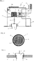
- the closure body in Figure 3 differs from the closure bodies of the Figures 1 and 2 in that it is not a solid body, but a hollow body. Specifically, a hollow cylinder is used here as the closure body, which is arranged above the inlet opening A1 of the drain A in such a way that its side wall completely encloses the inlet opening.
- Figure 4 which is a cross-sectional view taken along line XX of FIG Figure 3 is.
- the area 22 covered by the closure body 2 and shown here with transverse stripes is so large that it more than covers the opening cross section A1 of the drain A.
- this type of closure body is also referred to as being arranged above the drain.
- the hollow cylindrical closure body 2 In its closed position, as in Figure 3 shown, lowered to the water contact surface, the hollow cylindrical closure body 2 prevents the entry of water into the drain A as long as the water level does not exceed the height of the side wall of the hollow cylinder.
- the height of the side wall of the hollow cylinder 2 is selected so that it corresponds to the maximum desired or permissible water level on the water contact surface. If the water level continues to rise above this height, water flows over the edge of the hollow cylinder 2 and from there through the drain A. In this way, an emergency overflow can be implemented that works even if the closure body can no longer be lifted due to a defect by means of the actuating device 3, which is here connected to a cross strut of the closure body 2.
- FIG 5 shows an alternative arrangement of the in connection with Figure 3 discussed hollow cylinder closure body 2.
- the closure body 2 is used in a roof structure with permanent water storage WS, which is an alternative to that of Figure 2 represents.
- the height of the permanent water reservoir WS is set in a manner known per se by means of a pipe A2 which is inserted into the drain A with a corresponding protrusion.
- the inlet opening A1 into the drain A is thus above the water contact surface U. Water can only enter the drain A when the water level exceeds the protruding height of the pipe A2. In this case too, however, the drainage of water can be prevented by closing the drain A with the closure body 2.
- this is slipped over the pipe A2 so that water can only get into the drain when the water level is higher than the height of the side wall of the closure body.
- Figures 6 to 8 describe a particularly preferred embodiment of a hollow body closure body 2.
- the arrangement above the drain A basically corresponds to that in connection with Figures 3 to 5 was discussed.
- the closure body 2 itself again essentially has a hollow cylindrical shape, but in this case the lower edge is folded over towards the interior of the hollow cylinder and forms a contact surface 21 which is essentially parallel to the water contact surface. In order to achieve a better seal with respect to the water contact surface, the contact surface 21 is provided over the whole area with a layer 25 of an elastomeric plastic.
- the closure body 2 is arranged within an annular outer wall 6 which, in its lower wall area towards the water contact surface, has slot-shaped passage openings 60 through which water can pass into the interior.
- the openings 60 can be covered with a filter material in order to prevent dirt particles from entering the interior.
- the outer wall 6 serves to fasten parts of the actuating device for moving the closure body 2.
- a push rod 32 is guided through the central opening of the fastening ring 62 and is coupled to the drive device (for example a motor) of the actuating device 3 and can be moved up and down in the direction of the double arrow.
- An annular plate 37 is attached to a lower end of the push rod, for example between two screw nuts 36 which are screwed onto a thread at the lower end of the push rod.
- a pivot lever 30 is pivotably mounted on the ring plate 37.
- a fastening tab is used, for example, which protrudes upwards over the ring plate 37. It is shown here only with dashed lines because it does not lie within the cutting plane.
- a bolt 35 attached to the fastening strap is passed through a hole at the inner end of the pivot lever, so that the pivot lever 30 can be rotated about this bolt.
- the swing lever 30 has a curved shape. Approximately in the middle, in the most protruding area of the curvature, the pivot lever 30 has a further hole through which a further bolt 35, which is attached to a fork-shaped holder 63, is guided.
- the fork bracket 63 is attached to one of the support struts 61.
- pivot lever 30 The outer end of the pivot lever 30 is also perforated, a further bolt 35 is inserted into the perforation, and via this a second pivot lever 34 is pivotably connected to the pivot lever 30.
- a perforation at its opposite end is the second pivot lever 34 movably attached to a fastening tab 24, which in turn is firmly connected to the side wall 20 of the closure body 2.
- Swivel lever mechanisms are attached to the other two support struts 61 in the same way.
- the lifting and lowering of the hollow cylinder closure body 2 takes place by moving the push rod 32 up and down, which - controlled by the control device 4 - is driven by the motor of the actuating device. If the push rod 32 is pressed down, for example, it is followed by the inner end of the pivot lever 30, which is mounted on the ring plate 37. The pivot lever 30 therefore pivots about the central pin 35, which is mounted on the fork bracket 63, and its outer end moves upwards. As a result, the closure body 2, which is connected to the pivot lever 30 via the pivot lever 34, is raised upwards. When the push rod 32 is pulled up, the pivoting process takes place in the opposite direction, and the closure body 2 is lowered.
Landscapes
- Engineering & Computer Science (AREA)
- Architecture (AREA)
- Civil Engineering (AREA)
- Structural Engineering (AREA)
- Sewage (AREA)
Claims (11)
- Procédé de régulation du niveau d'eau sur une surface (U) de contact avec de l'eau ayant au moins une évacuation (A) et adoptant la forme d'une surface de toit ayant un système d'évacuation des eaux, comprenant :- un élément de fermeture (2) disposé à l'intérieur ou sur ladite au moins une évacuation (A) et configuré pour empêcher l'eau d'entrer dans ladite au moins une évacuation (A),- un dispositif d'actionnement (3) grâce auquel ledit élément de fermeture (2) peut être déplacé pour permettre à l'eau d'entrer dans ladite au moins une évacuation (A),- un dispositif de commande (4) pour commander le dispositif d'actionnement (3), et qui est configuré pour commander le dispositif d'actionnement (3) en fonction de données de météo évaluées/analysées, comprenant des données de prévisions météo reçues de manière extérieure et évaluées/analysées, comprenant des hauteurs de précipitation prévues, et- un dispositif récepteur (5) pour recevoir les données de prévisions météo, qui est connecté au dispositif de commande (4) à des fins de transmission des données météo reçues, comprenant les étapes de :caractérisé en ce que- réception des données météo au moyen du dispositif récepteur (5)- transmission des données météo du dispositif récepteur (5) au dispositif de commande (4),- comparaison des données de prévisions météo avec des valeurs de référence stockées dans une mémoire du dispositif de commande (4),- sélection des paramètres de commande en fonction des valeurs de référence déterminées et transmission des paramètres de commande au dispositif d'actionnement (3),- si nécessaire, actionnement du dispositif d'actionnement (3) et déplacement de l'élément de fermeture (2) pour ajuster le niveau de l'eau sur la surface (U) de contact avec l'eaula surface (U) de contact avec l'eau est la surface de toiture d'un toit végétalisé,les volumes d'afflux sont calculés pour les hauteurs de précipitation prévues par une application météo ou autre prévisions météorologiques prenant en compte les données de prévisions météorologiques,les volumes de stockage qui doivent être prévus pour absorber les hauteurs de précipitations prévues sont calculées sur la base de ces volumes d'afflux,les volumes de stockage sont utilisés pour calculer les quantités d'eau par unité de temps qui doivent être drainées de la surface (U) de contact avec l'eau pour fournir un espace pour les précipitations attendues,il est calculé pour combien de temps et, éventuellement, de combien ladite au moins une évacuation (A) a besoin d'être ouverte de manière à évacuer le volume d'écoulement calculé avant que l'événement de précipitation prévu ne se produise, etle dispositif de commande (4) actionne le dispositif d'actionnement (3) qui, à son tour, en fonction des paramètres calculés, ouvre totalement ou partiellement l'évacuation (A) pour la période de temps calculée par déplacement de l'élément de fermeture (2) de manière à évacuer le volume d'écoulement calculé.
- Procédé selon la revendication 1, dans lequel le dispositif récepteur (5) est un dispositif de communication mobile, et en particulier un smartphone.
- Procédé selon l'une quelconque des revendications 1 ou 2, dans lequel un émetteur connecté au dispositif de commande (4) est prévu pour transmettre des messages et/ou des données à un récepteur externe, et dans lequel en particulier le dispositif de communication mobile sert d'émetteur.
- Procédé selon l'une quelconque des revendications 1 à 3, dans lequel l'élément de fermeture (2) est configuré pour fermer l'ouverture d'entrée (A1) dans l'évacuation (A), et le dispositif d'actionnement (3) est configuré pour dégager l'élément de fermeture (2) de l'ouverture d'entrée (A1) en direction du haut ou pour le déplacer latéralement.
- Procédé selon l'une quelconque des revendications 1 à 3, dans lequel l'élément de fermeture (2) présente une paroi (20) qui entoure complètement l'ouverture d'entrée (A1) dans l'évacuation (A), et est configuré en particulier sous forme d'un corps creux, de manière préférée un cylindre creux, et dans lequel le dispositif d'actionnement (3) est configuré pour dégager l'élément de fermeture (2) de l'ouverture d'entrée (A1) en direction du haut ou pour le déplacer latéralement.
- Procédé selon la revendication 5, dans lequel la paroi (20) présente au moins l'une des caractéristiques suivantes :- elle ne possède pas d'ouvertures, au moins dans sa zone faisant face à la surface (U) de contact avec l'eau,- elle est repliée latéralement dans sa zone faisant face à la surface (U) de contact avec l'eau, la zone repliée formant une surface de contact (21) s'étendant de manière essentiellement parallèle à la surface (U) de contact avec l'eau, la surface de contact (21) étant de manière préférée recouverte d'un matériau élastiquement déformable.
- Procédé selon l'une quelconque des revendications 4 à 6, dans lequel l'élément de fermeture (2) est entouré d'une paroi extérieure (6) qui présente une ouverture de passage (60) au moins dans sa zone faisant face à la surface (U) de contact avec l'eau, l'élément de fermeture étant monté de manière à être mobile dans le sens de la hauteur de la paroi extérieure (6).
- Procédé selon l'une quelconque des revendications 1 à 6, dans lequel le dispositif d'actionnement (3) comprend un bras articulé (30), un système (31) de traction par câble, une tige de poussée ou de tirage (32), et/ou une tige crantée ou filetée (33).
- Procédé selon la revendication 7 ou 8, dans lequel l'élément de fermeture est relié à au moins un bras articulé (30) monté pivotant sur une entretoise de support (61) fixée à la paroi extérieure (6) et dans lequel une tige de poussée (32) est prévue pour actionner le bras articulé (30).
- Procédé selon l'une quelconque des revendications 1 à 9, comprenant au moins un module solaire (9) pour alimenter en électricité au moins l'un des dispositifs suivants :- le dispositif d'actionnement (3),- le dispositif de commande (4)- le dispositif récepteur (5)- l'émetteur.
- Système (1) d'évacuation des eaux pour une surface (U) de contact avec de l'eau ayant une évacuation (A) et adoptant la forme d'une surface de toit d'un toit végétalisé, comprenant :- un élément de fermeture (2) disposé à l'intérieur ou sur l'évacuation (A) et configuré pour empêcher l'eau d'entrer dans l'évacuation (A),- un dispositif d'actionnement (3) grâce auquel l'élément de fermeture (2) peut être déplacé pour permettre à l'eau d'entrer dans l'évacuation (A),- un dispositif de commande (4) pour commander le dispositif d'actionnement (3), et qui est configuré pour commander le dispositif d'actionnement (3) en fonction de données de prévisions météo reçues de manière extérieure et évaluées/analysées, comprenant des hauteurs de précipitation prévues, et- un dispositif récepteur (5) pour recevoir les données de prévisions météo, qui est connecté au dispositif de commande (4) à des fins de transmission des données météo reçues, configuré pour mettre en œuvre le procédé selon l'une quelconque des revendications 1 à 10.
Applications Claiming Priority (1)
| Application Number | Priority Date | Filing Date | Title |
|---|---|---|---|
| DE102016001187.4A DE102016001187A1 (de) | 2016-02-03 | 2016-02-03 | Wasserabflusssystem mit automatisch regelbarer Abflussmenge |
Publications (2)
| Publication Number | Publication Date |
|---|---|
| EP3202995A1 EP3202995A1 (fr) | 2017-08-09 |
| EP3202995B1 true EP3202995B1 (fr) | 2021-12-15 |
Family
ID=57144705
Family Applications (1)
| Application Number | Title | Priority Date | Filing Date |
|---|---|---|---|
| EP16002151.5A Active EP3202995B1 (fr) | 2016-02-03 | 2016-10-05 | Système d'évacuation d'eau à réglage automatique du débit |
Country Status (2)
| Country | Link |
|---|---|
| EP (1) | EP3202995B1 (fr) |
| DE (1) | DE102016001187A1 (fr) |
Families Citing this family (10)
| Publication number | Priority date | Publication date | Assignee | Title |
|---|---|---|---|---|
| DE102019004445A1 (de) * | 2019-06-24 | 2020-12-24 | Optigrün international AG | Wasserbilanzsteuerungssystem und Verfahren zu dessen Betrieb |
| IT202000021106A1 (it) | 2020-09-07 | 2022-03-07 | Climagruen Gmbh / Srl | Sistema per la ritenzione, accumulo e riciclo di acqua per tetti |
| DE102020005908A1 (de) | 2020-09-28 | 2022-03-31 | Optigrün international AG | Dachaufständerungssystem, dachaufständerung und verfahren zum aufbau einer dachaufständerung |
| CN113006243B (zh) * | 2021-01-27 | 2022-11-25 | 广东智铭设计有限公司 | 一种市政排水用的雨水井 |
| CN113293845B (zh) * | 2021-07-06 | 2022-08-16 | 郑州市交通规划勘察设计研究院 | 道路施工排水系统 |
| CN115928779B (zh) * | 2022-12-30 | 2025-10-21 | 福建嘉宜建筑工程有限公司 | 一种房建施工工地排水系统 |
| AT527001B1 (de) | 2023-02-17 | 2024-11-15 | Johann Trummer | Vorrichtung und Verfahren zur Steuerung eines Wasserpegels auf einem Flachdach |
| DE102024108980A1 (de) * | 2024-03-28 | 2025-10-02 | Optigrün international AG | Niederschlagsmanagement-system und -verfahren |
| DE102024108978A1 (de) * | 2024-03-28 | 2025-10-02 | Optigrün international AG | Niederschlagsmanagement-system |
| DE102024108979A1 (de) * | 2024-03-28 | 2025-10-02 | Optigrün international AG | Kontrollschacht für ein dach mit wasserführender schicht und dachaufbau mit kontrollschacht |
Family Cites Families (3)
| Publication number | Priority date | Publication date | Assignee | Title |
|---|---|---|---|---|
| BE791137A (fr) * | 1971-12-14 | 1973-03-01 | Esser Kg Klaus | Dispositif pour le dosage de la quantite d'eau qui passe au niveau d'ecoulements de toit |
| DE19852561C1 (de) | 1998-11-13 | 2000-07-06 | Harzmann Optima Marketing Und | Wasserabflußsystem für Dachflächen |
| US20150218785A1 (en) * | 2013-12-20 | 2015-08-06 | Rainbank, Inc. | Automated roof runoff management system |
-
2016
- 2016-02-03 DE DE102016001187.4A patent/DE102016001187A1/de not_active Withdrawn
- 2016-10-05 EP EP16002151.5A patent/EP3202995B1/fr active Active
Non-Patent Citations (1)
| Title |
|---|
| None * |
Also Published As
| Publication number | Publication date |
|---|---|
| DE102016001187A1 (de) | 2017-08-03 |
| EP3202995A1 (fr) | 2017-08-09 |
Similar Documents
| Publication | Publication Date | Title |
|---|---|---|
| EP3202995B1 (fr) | Système d'évacuation d'eau à réglage automatique du débit | |
| EP2982810B1 (fr) | Systeme d'evacuation d'eau a reglage automatique du debit | |
| DE102007030305B4 (de) | Wasserbewirtschaftungssystem für urbane und/oder landwirtschaftlich genutzte Flächen und Verfahren zu seiner Bereitstellung | |
| EP2085527B1 (fr) | Installation d'exploitation d'eau de pluie | |
| EP3757300B1 (fr) | Système de commande du bilan hydrique et son procédé de fonctionnement | |
| EP4210473A1 (fr) | Dispositif d'irrigation et de drainage et/ou dispositif de stockage d'eau, de préférence pour la gestion de l'eau, en particulier pour l'irrigation d'espaces (verts) et/ou de plantes | |
| DE19852561C1 (de) | Wasserabflußsystem für Dachflächen | |
| AT524209B1 (de) | System zur versickerung von niederschlagswasser | |
| DE3418813A1 (de) | Entwaesserungssystem | |
| EP4706380A2 (fr) | Puits pour la régulation de l'eau souterraine | |
| DE19655159C2 (de) | Bodenfilter für Regen- und Abwasser mit Dichtbahn | |
| DE19610743C2 (de) | Bodenfilter für Regen- und Abwasser | |
| DE19700985A1 (de) | Versickerungseinrichtung | |
| AT527517B1 (de) | Anordnung zur begrünten Retention von Niederschlagswasser | |
| AT527001B1 (de) | Vorrichtung und Verfahren zur Steuerung eines Wasserpegels auf einem Flachdach | |
| DE102021128859A1 (de) | Regenwasserspeicher zum zwischenspeichern von regenwasser sowie dessen verwendung zur vermeidung von überlastungen von kanalisation und gewässern in folge eines starkregenereignisses | |
| EP4623671A1 (fr) | Système et procédé de gestion de précipitations | |
| EP4506518A1 (fr) | Dispositif d'évacuation d'eau de surface | |
| EP2517551A2 (fr) | Grille de protection d'arbre à rainures et dispositif de nettoyage pour le drainage et l'infiltration | |
| DE202025105906U1 (de) | Fassadenanordnung, und Bausatz zur Herstellung einer Fassadenanordnung | |
| DE19830192B4 (de) | Wasserbauwerk und Verfahren zur Wasserentlastung einer Abwasseranlage | |
| EP4624682A1 (fr) | Système de gestion de précipitations | |
| DE202024102417U1 (de) | Filteranordnung | |
| DE29807337U1 (de) | Abflußmengenregelvorrichtung für Regenrückhaltebecken | |
| DE202006006098U1 (de) | Schachtanordnung |
Legal Events
| Date | Code | Title | Description |
|---|---|---|---|
| PUAI | Public reference made under article 153(3) epc to a published international application that has entered the european phase |
Free format text: ORIGINAL CODE: 0009012 |
|
| STAA | Information on the status of an ep patent application or granted ep patent |
Free format text: STATUS: THE APPLICATION HAS BEEN PUBLISHED |
|
| STAA | Information on the status of an ep patent application or granted ep patent |
Free format text: STATUS: REQUEST FOR EXAMINATION WAS MADE |
|
| AK | Designated contracting states |
Kind code of ref document: A1 Designated state(s): AL AT BE BG CH CY CZ DE DK EE ES FI FR GB GR HR HU IE IS IT LI LT LU LV MC MK MT NL NO PL PT RO RS SE SI SK SM TR |
|
| AX | Request for extension of the european patent |
Extension state: BA ME |
|
| 17P | Request for examination filed |
Effective date: 20170718 |
|
| RBV | Designated contracting states (corrected) |
Designated state(s): AL AT BE BG CH CY CZ DE DK EE ES FI FR GB GR HR HU IE IS IT LI LT LU LV MC MK MT NL NO PL PT RO RS SE SI SK SM TR |
|
| STAA | Information on the status of an ep patent application or granted ep patent |
Free format text: STATUS: EXAMINATION IS IN PROGRESS |
|
| 17Q | First examination report despatched |
Effective date: 20200930 |
|
| GRAP | Despatch of communication of intention to grant a patent |
Free format text: ORIGINAL CODE: EPIDOSNIGR1 |
|
| STAA | Information on the status of an ep patent application or granted ep patent |
Free format text: STATUS: GRANT OF PATENT IS INTENDED |
|
| INTG | Intention to grant announced |
Effective date: 20210831 |
|
| GRAS | Grant fee paid |
Free format text: ORIGINAL CODE: EPIDOSNIGR3 |
|
| GRAA | (expected) grant |
Free format text: ORIGINAL CODE: 0009210 |
|
| STAA | Information on the status of an ep patent application or granted ep patent |
Free format text: STATUS: THE PATENT HAS BEEN GRANTED |
|
| AK | Designated contracting states |
Kind code of ref document: B1 Designated state(s): AL AT BE BG CH CY CZ DE DK EE ES FI FR GB GR HR HU IE IS IT LI LT LU LV MC MK MT NL NO PL PT RO RS SE SI SK SM TR |
|
| REG | Reference to a national code |
Ref country code: GB Ref legal event code: FG4D Free format text: NOT ENGLISH Ref country code: CH Ref legal event code: EP |
|
| REG | Reference to a national code |
Ref country code: IE Ref legal event code: FG4D Free format text: LANGUAGE OF EP DOCUMENT: GERMAN Ref country code: DE Ref legal event code: R096 Ref document number: 502016014260 Country of ref document: DE |
|
| REG | Reference to a national code |
Ref country code: AT Ref legal event code: REF Ref document number: 1455608 Country of ref document: AT Kind code of ref document: T Effective date: 20220115 |
|
| REG | Reference to a national code |
Ref country code: NL Ref legal event code: FP |
|
| REG | Reference to a national code |
Ref country code: LT Ref legal event code: MG9D |
|
| PG25 | Lapsed in a contracting state [announced via postgrant information from national office to epo] |
Ref country code: RS Free format text: LAPSE BECAUSE OF FAILURE TO SUBMIT A TRANSLATION OF THE DESCRIPTION OR TO PAY THE FEE WITHIN THE PRESCRIBED TIME-LIMIT Effective date: 20211215 Ref country code: LT Free format text: LAPSE BECAUSE OF FAILURE TO SUBMIT A TRANSLATION OF THE DESCRIPTION OR TO PAY THE FEE WITHIN THE PRESCRIBED TIME-LIMIT Effective date: 20211215 Ref country code: FI Free format text: LAPSE BECAUSE OF FAILURE TO SUBMIT A TRANSLATION OF THE DESCRIPTION OR TO PAY THE FEE WITHIN THE PRESCRIBED TIME-LIMIT Effective date: 20211215 Ref country code: BG Free format text: LAPSE BECAUSE OF FAILURE TO SUBMIT A TRANSLATION OF THE DESCRIPTION OR TO PAY THE FEE WITHIN THE PRESCRIBED TIME-LIMIT Effective date: 20220315 |
|
| PG25 | Lapsed in a contracting state [announced via postgrant information from national office to epo] |
Ref country code: SE Free format text: LAPSE BECAUSE OF FAILURE TO SUBMIT A TRANSLATION OF THE DESCRIPTION OR TO PAY THE FEE WITHIN THE PRESCRIBED TIME-LIMIT Effective date: 20211215 Ref country code: NO Free format text: LAPSE BECAUSE OF FAILURE TO SUBMIT A TRANSLATION OF THE DESCRIPTION OR TO PAY THE FEE WITHIN THE PRESCRIBED TIME-LIMIT Effective date: 20220315 Ref country code: LV Free format text: LAPSE BECAUSE OF FAILURE TO SUBMIT A TRANSLATION OF THE DESCRIPTION OR TO PAY THE FEE WITHIN THE PRESCRIBED TIME-LIMIT Effective date: 20211215 Ref country code: HR Free format text: LAPSE BECAUSE OF FAILURE TO SUBMIT A TRANSLATION OF THE DESCRIPTION OR TO PAY THE FEE WITHIN THE PRESCRIBED TIME-LIMIT Effective date: 20211215 Ref country code: GR Free format text: LAPSE BECAUSE OF FAILURE TO SUBMIT A TRANSLATION OF THE DESCRIPTION OR TO PAY THE FEE WITHIN THE PRESCRIBED TIME-LIMIT Effective date: 20220316 |
|
| PG25 | Lapsed in a contracting state [announced via postgrant information from national office to epo] |
Ref country code: SM Free format text: LAPSE BECAUSE OF FAILURE TO SUBMIT A TRANSLATION OF THE DESCRIPTION OR TO PAY THE FEE WITHIN THE PRESCRIBED TIME-LIMIT Effective date: 20211215 Ref country code: SK Free format text: LAPSE BECAUSE OF FAILURE TO SUBMIT A TRANSLATION OF THE DESCRIPTION OR TO PAY THE FEE WITHIN THE PRESCRIBED TIME-LIMIT Effective date: 20211215 Ref country code: RO Free format text: LAPSE BECAUSE OF FAILURE TO SUBMIT A TRANSLATION OF THE DESCRIPTION OR TO PAY THE FEE WITHIN THE PRESCRIBED TIME-LIMIT Effective date: 20211215 Ref country code: PT Free format text: LAPSE BECAUSE OF FAILURE TO SUBMIT A TRANSLATION OF THE DESCRIPTION OR TO PAY THE FEE WITHIN THE PRESCRIBED TIME-LIMIT Effective date: 20220418 Ref country code: ES Free format text: LAPSE BECAUSE OF FAILURE TO SUBMIT A TRANSLATION OF THE DESCRIPTION OR TO PAY THE FEE WITHIN THE PRESCRIBED TIME-LIMIT Effective date: 20211215 Ref country code: EE Free format text: LAPSE BECAUSE OF FAILURE TO SUBMIT A TRANSLATION OF THE DESCRIPTION OR TO PAY THE FEE WITHIN THE PRESCRIBED TIME-LIMIT Effective date: 20211215 Ref country code: CZ Free format text: LAPSE BECAUSE OF FAILURE TO SUBMIT A TRANSLATION OF THE DESCRIPTION OR TO PAY THE FEE WITHIN THE PRESCRIBED TIME-LIMIT Effective date: 20211215 |
|
| PG25 | Lapsed in a contracting state [announced via postgrant information from national office to epo] |
Ref country code: PL Free format text: LAPSE BECAUSE OF FAILURE TO SUBMIT A TRANSLATION OF THE DESCRIPTION OR TO PAY THE FEE WITHIN THE PRESCRIBED TIME-LIMIT Effective date: 20211215 |
|
| REG | Reference to a national code |
Ref country code: DE Ref legal event code: R097 Ref document number: 502016014260 Country of ref document: DE |
|
| PG25 | Lapsed in a contracting state [announced via postgrant information from national office to epo] |
Ref country code: IS Free format text: LAPSE BECAUSE OF FAILURE TO SUBMIT A TRANSLATION OF THE DESCRIPTION OR TO PAY THE FEE WITHIN THE PRESCRIBED TIME-LIMIT Effective date: 20220415 |
|
| PLBE | No opposition filed within time limit |
Free format text: ORIGINAL CODE: 0009261 |
|
| STAA | Information on the status of an ep patent application or granted ep patent |
Free format text: STATUS: NO OPPOSITION FILED WITHIN TIME LIMIT |
|
| PG25 | Lapsed in a contracting state [announced via postgrant information from national office to epo] |
Ref country code: DK Free format text: LAPSE BECAUSE OF FAILURE TO SUBMIT A TRANSLATION OF THE DESCRIPTION OR TO PAY THE FEE WITHIN THE PRESCRIBED TIME-LIMIT Effective date: 20211215 Ref country code: AL Free format text: LAPSE BECAUSE OF FAILURE TO SUBMIT A TRANSLATION OF THE DESCRIPTION OR TO PAY THE FEE WITHIN THE PRESCRIBED TIME-LIMIT Effective date: 20211215 |
|
| 26N | No opposition filed |
Effective date: 20220916 |
|
| PG25 | Lapsed in a contracting state [announced via postgrant information from national office to epo] |
Ref country code: SI Free format text: LAPSE BECAUSE OF FAILURE TO SUBMIT A TRANSLATION OF THE DESCRIPTION OR TO PAY THE FEE WITHIN THE PRESCRIBED TIME-LIMIT Effective date: 20211215 |
|
| PG25 | Lapsed in a contracting state [announced via postgrant information from national office to epo] |
Ref country code: MC Free format text: LAPSE BECAUSE OF FAILURE TO SUBMIT A TRANSLATION OF THE DESCRIPTION OR TO PAY THE FEE WITHIN THE PRESCRIBED TIME-LIMIT Effective date: 20211215 Ref country code: IT Free format text: LAPSE BECAUSE OF FAILURE TO SUBMIT A TRANSLATION OF THE DESCRIPTION OR TO PAY THE FEE WITHIN THE PRESCRIBED TIME-LIMIT Effective date: 20211215 |
|
| P01 | Opt-out of the competence of the unified patent court (upc) registered |
Effective date: 20230515 |
|
| PG25 | Lapsed in a contracting state [announced via postgrant information from national office to epo] |
Ref country code: LU Free format text: LAPSE BECAUSE OF NON-PAYMENT OF DUE FEES Effective date: 20221005 |
|
| REG | Reference to a national code |
Ref country code: DE Ref legal event code: R082 Ref document number: 502016014260 Country of ref document: DE Representative=s name: MAIWALD GMBH, DE |
|
| PG25 | Lapsed in a contracting state [announced via postgrant information from national office to epo] |
Ref country code: IE Free format text: LAPSE BECAUSE OF NON-PAYMENT OF DUE FEES Effective date: 20221005 |
|
| PG25 | Lapsed in a contracting state [announced via postgrant information from national office to epo] |
Ref country code: HU Free format text: LAPSE BECAUSE OF FAILURE TO SUBMIT A TRANSLATION OF THE DESCRIPTION OR TO PAY THE FEE WITHIN THE PRESCRIBED TIME-LIMIT; INVALID AB INITIO Effective date: 20161005 |
|
| PG25 | Lapsed in a contracting state [announced via postgrant information from national office to epo] |
Ref country code: CY Free format text: LAPSE BECAUSE OF FAILURE TO SUBMIT A TRANSLATION OF THE DESCRIPTION OR TO PAY THE FEE WITHIN THE PRESCRIBED TIME-LIMIT Effective date: 20211215 |
|
| PG25 | Lapsed in a contracting state [announced via postgrant information from national office to epo] |
Ref country code: MK Free format text: LAPSE BECAUSE OF FAILURE TO SUBMIT A TRANSLATION OF THE DESCRIPTION OR TO PAY THE FEE WITHIN THE PRESCRIBED TIME-LIMIT Effective date: 20211215 |
|
| PG25 | Lapsed in a contracting state [announced via postgrant information from national office to epo] |
Ref country code: TR Free format text: LAPSE BECAUSE OF FAILURE TO SUBMIT A TRANSLATION OF THE DESCRIPTION OR TO PAY THE FEE WITHIN THE PRESCRIBED TIME-LIMIT Effective date: 20211215 |
|
| PG25 | Lapsed in a contracting state [announced via postgrant information from national office to epo] |
Ref country code: MT Free format text: LAPSE BECAUSE OF FAILURE TO SUBMIT A TRANSLATION OF THE DESCRIPTION OR TO PAY THE FEE WITHIN THE PRESCRIBED TIME-LIMIT Effective date: 20211215 |
|
| REG | Reference to a national code |
Ref country code: CH Ref legal event code: U11 Free format text: ST27 STATUS EVENT CODE: U-0-0-U10-U11 (AS PROVIDED BY THE NATIONAL OFFICE) Effective date: 20251101 |
|
| PGFP | Annual fee paid to national office [announced via postgrant information from national office to epo] |
Ref country code: NL Payment date: 20251023 Year of fee payment: 10 |
|
| PGFP | Annual fee paid to national office [announced via postgrant information from national office to epo] |
Ref country code: DE Payment date: 20251029 Year of fee payment: 10 |
|
| PGFP | Annual fee paid to national office [announced via postgrant information from national office to epo] |
Ref country code: GB Payment date: 20251024 Year of fee payment: 10 |
|
| PGFP | Annual fee paid to national office [announced via postgrant information from national office to epo] |
Ref country code: AT Payment date: 20251021 Year of fee payment: 10 |
|
| PGFP | Annual fee paid to national office [announced via postgrant information from national office to epo] |
Ref country code: FR Payment date: 20251029 Year of fee payment: 10 |
|
| PGFP | Annual fee paid to national office [announced via postgrant information from national office to epo] |
Ref country code: BE Payment date: 20251022 Year of fee payment: 10 |
|
| PGFP | Annual fee paid to national office [announced via postgrant information from national office to epo] |
Ref country code: CH Payment date: 20251101 Year of fee payment: 10 |