EP3202999B1 - Betätigungshandhabe und einsatzkörper für eine betätigungshandhabe - Google Patents
Betätigungshandhabe und einsatzkörper für eine betätigungshandhabe Download PDFInfo
- Publication number
- EP3202999B1 EP3202999B1 EP17152823.5A EP17152823A EP3202999B1 EP 3202999 B1 EP3202999 B1 EP 3202999B1 EP 17152823 A EP17152823 A EP 17152823A EP 3202999 B1 EP3202999 B1 EP 3202999B1
- Authority
- EP
- European Patent Office
- Prior art keywords
- handle
- contact area
- locking
- wear protection
- protection means
- Prior art date
- Legal status (The legal status is an assumption and is not a legal conclusion. Google has not performed a legal analysis and makes no representation as to the accuracy of the status listed.)
- Active
Links
Images


Classifications
-
- E—FIXED CONSTRUCTIONS
- E05—LOCKS; KEYS; WINDOW OR DOOR FITTINGS; SAFES
- E05B—LOCKS; ACCESSORIES THEREFOR; HANDCUFFS
- E05B15/00—Other details of locks; Parts for engagement by bolts of fastening devices
- E05B15/16—Use of special materials for parts of locks
- E05B15/1614—Use of special materials for parts of locks of hard materials, to prevent drilling
-
- E—FIXED CONSTRUCTIONS
- E05—LOCKS; KEYS; WINDOW OR DOOR FITTINGS; SAFES
- E05B—LOCKS; ACCESSORIES THEREFOR; HANDCUFFS
- E05B3/00—Fastening knobs or handles to lock or latch parts
-
- E—FIXED CONSTRUCTIONS
- E05—LOCKS; KEYS; WINDOW OR DOOR FITTINGS; SAFES
- E05B—LOCKS; ACCESSORIES THEREFOR; HANDCUFFS
- E05B3/00—Fastening knobs or handles to lock or latch parts
- E05B3/04—Fastening the knob or the handle shank to the spindle by screws, springs or snap bolts
-
- E—FIXED CONSTRUCTIONS
- E05—LOCKS; KEYS; WINDOW OR DOOR FITTINGS; SAFES
- E05B—LOCKS; ACCESSORIES THEREFOR; HANDCUFFS
- E05B3/00—Fastening knobs or handles to lock or latch parts
- E05B2003/006—Fastening knobs or handles to the spindle by means of tilt-plates
Definitions
- the invention relates to an operating handle according to the preamble of claim 1. Furthermore, the invention relates to an insert body for an operating handle according to the preamble of claim 13.
- Actuating handles are known in numerous configurations. They are used, for example, to open and close a window, a door or the like, with a handle mostly via a driver, e.g. a square pin is designed for the rotary entrainment of an actuating device in the window or door sash, such as a window gear or a lock nut.
- a driver e.g. a square pin is designed for the rotary entrainment of an actuating device in the window or door sash, such as a window gear or a lock nut.
- the driver In addition to the torque, the driver usually also has to transmit axial tensile forces, e.g. in the case of door fittings.
- the connection between the handle and the driver must be designed so that both are axially and non-rotatably anchored to one another after assembly, whereby - depending on the design of the window or the door - an adaptation of the pin connection to the respective thickness of the window frame or the door leaf must be possible.
- an actuating handle in which a device is provided between the handle and the driver element which allows a relative movement between the handle and the driver element in a first axial direction and blocks it in the opposite axial direction. This makes it possible to simply slide the handle onto the driver element which is inserted laterally into the door leaf and protrudes through a lock nut until the desired insertion depth is reached.
- a device is provided in the handle which has a locking or clamping element which is acted upon by a spring force and which can be brought into force, positive and / or frictional engagement with the driver element.
- the locking element can be designed as a locking frame which has an angular recess in the center through which the driver element can be guided, so that the locking frame encloses the driver element at least in sections.
- the locking effect is achieved in that the spring force presses the locking or clamping elements against a contact surface, so that the locking or clamping elements are tilted into an inclined position and the edges of the recess of the locking or clamping elements press against the driver element and thus an axial movement of the Lock the driver element in one direction.
- Similar devices are from the EP 2 241 704 A1 and the JP 2001 254538 A known.
- the disadvantage here is that the pivotably mounted locking or clamping elements are pressed directly onto the contact area by the spring force. If forces act on the locking device after installation and prolonged, intended use of the operating handle, ie the opening and closing of a door or window, the contact area of the locking or clamping elements can be severely worn. The cause of this wear and tear is that when tensile or compressive forces act, the locking or clamping elements move and rub on the contact area. The resulting wear can lead to a deterioration in the locking function. In particular, abrasion can lead to a change in the geometry of the contact area, so that the function of a stop, which enables the inclined position of the locking or clamping elements required for the locking effect, can no longer be fulfilled.
- the aim of the invention is to overcome these and other disadvantages of the prior art and to create an actuating handle that enables a tool-free and permanently reliable connection between the driver and the handle, with the locking effect being maintained even with prolonged and frequently repeated use of the actuating handle remains.
- a locking device being provided between the handle and the driver element, which is designed such that the introduction of the driver element into the handle can be brought about in a first direction and locked in the opposite direction, the locking device having at least one locking element which is acted upon by a spring force and which can be brought into force, positive and / or frictional engagement with the driver element is, wherein the locking element is designed as a locking frame that encloses the driver element at least in sections, and wherein the locking element is pivotably mounted and is supported on a contact area in the area of the handle, the invention provides that a coating or a separate body in the contact area a v wear-resistant and / or hardened material is arranged or designed as wear protection means, wherein the wear protection means has a different material than the contact area, and wherein the locking element is supported essentially on or on the wear protection means.
- the wear protection agent can be selected from higher quality materials with better wear protection properties.
- wear-resistant hard materials can also be used as material for the wear protection agent according to the invention.
- metallic hard materials such as carbides, nitrides, carbonitrides, borides and silicides of the transition metals, hard material mixed crystals (e.g. TiC-WC, TiC-TaC-WC, TiC-TiN), double carbides and complex carbides (e.g. Co 3 W 3 C, Ni 3 W 3 C) and intermetallic compounds (e.g. W-Co, W-Os, W-Re, W-Ir, Mo-Be).
- metallic hard materials such as carbides, nitrides, carbonitrides, borides and silicides of the transition metals
- hard material mixed crystals e.g. TiC-WC, TiC-TaC-WC, TiC-TiN
- double carbides and complex carbides e.g. Co 3 W 3 C, Ni 3 W 3 C
- intermetallic compounds e.g. W-Co, W-Os,
- the non-metallic hard materials are carbides, nitrides and oxides of main group elements and some modifications of the pure elements, such as natural and synthetic diamond, corundum (Al 2 O 3 ), natural and synthetic precious and semi-precious stones (e.g. sapphire, ruby, zircon), boron, Boron carbide (B 4 C), cubic boron nitride (BN, "Borazon”), beryllium carbide, silicon carbide (SiC), silicon nitride (Si 3 N 4 ) and aluminum nitride (AlN) are possible.
- Composite materials with high wear resistance that consist of more than just one material are also conceivable.
- a coating for the use of a coating as a wear protection agent, among other things, metal alloys are known as wear-resistant coatings. These alloys are applied to the base body by spraying or welding and adhere to it Fusion, adhesion or the formation of an intermediate layer. Applying the coating by painting is also conceivable.
- the advantage of the coating is that the coating can extend over the entire contact surface and thus its wear protection property is extended to the entire stressed surface. In addition, in the case of a coating, no additional spatial body has to be introduced into the device, which simplifies production and assembly.
- the blocking element When using a separate body as a wear protection means, the blocking element is essentially supported on this separate body, so that direct contact between the blocking element and the contact area is avoided and the contact area cannot be worn out.
- the body can be connected to the contact area, in particular by gluing or welding, so that a load-bearing connection can be achieved between the body and the wear protection means.
- the wear protection means is a separate body which is at least partially received in a bore in the contact area.
- the arrangement of the wear protection means can be determined by the arrangement of the bore. In this way, the installation of the wear protection means can be carried out relatively easily, and damaged wear protection means can be replaced in a simple manner. If the wear protection agent is to be permanently attached, this could be achieved, for example, by means of hot isostatic pressing with the contact area.
- the wear protection means is designed as a separate, rotationally symmetrical, in particular roller-shaped or spherically symmetrical body.
- the locking element thus has little or no contact with the contact area, which is usually made of zamak alloy in the zinc die-casting process and is therefore not very wear-resistant, so that wear on the contact surface is avoided.
- a spherical body as a wear protection means has the advantage that it offers only a small contact area for the locking element.
- the locking device is formed in the handle neck.
- the handle has a main handle part and a handle neck, the handle neck having a recess at the end and the locking device being formed in the recess. It is particularly advantageous if an insert body is inserted into the front side of the recess, the locking element being pressed by the spring force of a spring which is supported in the handle neck against the wear protection means which is arranged on the contact area. It is particularly advantageous if the contact area is formed on the insert body.
- the insert body is designed as a socket which is inserted in the recess in the handle neck, the locking element being arranged in the socket and the locking element being acted upon by the spring force of a spring which is arranged in the socket.
- the insert body with the locking device can be designed as a preassembled unit. This unit can then simply be screwed, glued or pressed into the handle neck of the handle. This not only simplifies warehousing but can also be installed in any door or window handle at the factory, depending on the customer's requirements.
- the contact area is formed by an inclined surface of the insert body. It is particularly advantageous if the direction of inclination of the inclined surface runs diagonally to the cross section of the driver element.
- the inclined surface ensures that the locking element always forms a maximally large lever arm.
- no separate support edge is required as an axis of rotation, so that the blocking element can be produced quickly and inexpensively, in particular by punching.
- the locking element is inclined to the axial direction and is at least on the edge of the wear protection means. In this way, the contact area between the wear protection means and the locking element can be additionally reduced while the locking effect remains the same.
- the abrasive forces only act on a particularly small, almost punctiform area of the wear protection agent.
- the invention relates to an insert body for an actuating handle which is fixed or fixable in a handle neck of the actuating handle, the insert body being designed as a socket which can be inserted at the end into the handle neck of an actuating handle, a locking device being formed in the insert body which has at least one locking element which is acted upon by a spring force and wherein the The locking element is designed as a locking frame and the locking element is pivotably mounted and is supported on a contact area in the interior of the socket, wherein according to the invention a wear protection agent is arranged in the contact area, the locking element being supported essentially on or on the wear protection agent.
- the wear protection agent forms part of the contact area on which the blocking element rests.
- the wear protection agent prevents direct contact between the blocking element and the contact area, so that wear and tear on the contact area can be prevented effectively and precisely. This leads to a longer service life of the plant area and to the preservation of its functionality. The durability of the locking effect is thus guaranteed even with prolonged and frequently repeated use of the actuating handle.
- the insert body can be prefabricated as a pre-encapsulated unit.
- An insert body designed as a socket in this way can be manufactured as an independent component and easily combined with handles to form an actuating handle. The unit can then simply be screwed, glued or pressed into the handle neck of the handle.
- Such an insert not only simplifies storage but can also be provided at the factory in any door or window handle, depending on the customer's requirements.
- the wear protection agent has a different material than the contact area. This allows the advantages of two different materials to be optimally used. While the contact area and the parts that form this contact area can be produced inexpensively and quickly by die casting from metal, in particular by zinc die casting, the wear protection agent can be selected from higher quality materials with better wear protection properties.
- the wear protection means can particularly advantageously consist of a hardened material and / or wear-resistant material.
- a targeted change and transformation of its structure increases the strength. This increase in strength brings with it a higher wear resistance, so that such a material, in particular a hardened metal such as hardened steel, can be used particularly effectively as a wear protection agent.
- wear-resistant hard materials can also be used as material for the wear protection agent according to the invention.
- metallic hard materials such as carbides, nitrides, carbonitrides, borides and silicides of transition metals, hard mixed crystals (e.g. TiC-WC, TiC-TaC-WC, TiC-TiN), double carbides and complex carbides (e.g. Co3W3C, Ni3W3C) and intermetallic compounds (e.g. W-Co, W-Os, W-Re, W -Ir, Mo-Be).
- metallic hard materials such as carbides, nitrides, carbonitrides, borides and silicides of transition metals, hard mixed crystals (e.g. TiC-WC, TiC-TaC-WC, TiC-TiN), double carbides and complex carbides (e.g. Co3W3C, Ni3W3C) and intermetallic compounds (e.g. W-Co, W-Os, W-Re, W
- the non-metallic hard materials are carbides, nitrides and oxides of main group elements and some modifications of the pure elements, such as natural and synthetic diamond, corundum (AI2O3), natural and synthetic precious and semi-precious stones (e.g. sapphire, ruby, zircon), boron, boron carbide (B4C ), cubic boron nitride (BN, "Borazon”), beryllium carbide, silicon carbide (SiC), silicon nitride (Si3N4) and aluminum nitride (AIN).
- Composite materials with high wear resistance that consist of more than just one material are also conceivable.
- the wear protection agent is a coating.
- Metal alloys are known as wear-resistant coatings. These alloys are applied to the base body by spraying or welding and adhere to it by fusing, by adhesion or by forming an intermediate layer. Applying the coating by painting is also conceivable.
- the advantage of the coating is that the coating can extend over the entire contact surface and thus its wear protection property is extended to the entire stressed surface. In addition, in the case of a coating, no additional spatial body has to be introduced into the device, which simplifies production and assembly.
- the wear protection means is a separate body.
- the blocking element is essentially supported on this separate body, so that direct contact between the blocking element and the contact area is avoided and the contact area cannot be worn down.
- the body can be connected to the contact area, in particular by gluing or welding, so that a load-bearing connection can be achieved between the body and the wear protection means.
- the wear protection means is a separate body which is at least partially received in a bore in the contact area.
- the arrangement of the wear protection means can be determined by the arrangement of the bore. In this way, the installation of the wear protection means can be carried out relatively easily, and damaged wear protection means can be replaced in a simple manner. If the wear protection agent is to be permanently attached, this could be achieved, for example, by means of hot isostatic pressing with the contact area. It has proven to be advantageous if the wear protection means is designed as a separate, rotationally symmetrical, in particular roller-shaped or spherically symmetrical body.
- the locking element thus has little or no contact with the contact area, which is usually made of zamak alloy in the zinc die-casting process and is therefore not very wear-resistant, so that wear on the contact surface is avoided.
- a spherical body as a wear protection means has the advantage that it offers only a small contact area for the locking element.
- the locking element is arranged in the socket and the locking element is acted upon by the spring force of a spring which is arranged in the socket. It is particularly advantageous if the contact area is formed by an inclined surface in the interior of the socket.
- the locking element is inclined to the axial direction and is at least on the edge of the wear protection means. In this way, the contact area between the wear protection means and the locking element can be additionally reduced while the locking effect remains the same.
- the abrasive forces only act on a particularly small, almost punctiform area of the wear protection agent.
- Fig. 1 shows a schematic representation of an operating handle 10, as it is used, for example, as a door handle for opening and closing doors.
- the actuating handle 10 essentially consists of a main handle part 22 which, for example, when used as a door set or door fitting, can be connected to an opposite handle on the opposite side of a door leaf via a driver element 30.
- the driver element 30 is rectangular or square in cross section and can be inserted into a corresponding receptacle in the main handle part 22, so that when the main handle part 22 is actuated on one side of the door leaf, the opposite main handle part 22 is on the opposite side of the door leaf moved synchronously.
- the driver element also called a square pin, usually penetrates a lock nut in a door lock, which is inserted into the front of the door leaf.
- the handle main part 22 is - like Fig. 1 shows - in the handle 20, which is usually gripped by the hand of the operator when the handle is operated, and a handle neck divided.
- the handle neck 23 is arranged at right angles to the handle 20.
- the driver element 30 is first inserted into a corresponding receptacle in the handle neck along a first displacement direction R1. The driver element 30 is then guided through a corresponding recess out of the door leaf or the window frame and, on the opposite side, likewise introduced into the handle neck 23 of a counterpart handle main part.
- the driver element 30 is inserted into the handle neck 23 of the main handle part along a first direction R1, but cannot then be removed again from the handle neck 23 without using appropriate tools along a direction R2 opposite to the first direction R1 .
- a locking device 40 is provided according to the invention, which is arranged in an insert body 70.
- the insert body 70 is in turn inserted into a corresponding recess in the handle neck 23 and is permanently fastened in the handle neck 23, for example by being pressed.
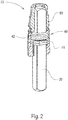
- the Fig. 2 shows a longitudinal section through such an insert body 70, which can be produced from die-cast zinc in a die-casting process, for example.
- the insert body 70 is designed as a bushing 80 which can be inserted into a corresponding recess 24 of the handle neck 23.
- the inner region of the bushing 80 forms a guide into which the driver element 30 can be inserted when the main handle part 22 is assembled.
- a recess is provided within the socket 80 in which the locking device 40 is provided.
- the locking device 40 is composed of a locking element 41 and a restoring element or a spring 42.
- the spring 42 is arranged on a stop of the bushing 80 in such a way that the spring 42 exerts a force F on the locking element 41 in the direction R2 when it is compressed.
- the locking element 41 is in turn designed as a disk-shaped element with a recess, the shape of the recess corresponding to the cross-sectional shape of the driver element 30. It is provided that the dimensions of the recess are designed so that when the driver element 30 is inserted into the recess, an air gap remains between the driver element 30 and the walls of the recess, so that a transverse play of the driver element 30 with respect to the locking element 41 remains.
- the Fig. 3 shows the insert body of the Fig. 2 without a locking element 41, driver element 30 inserted into the insert body 70 and without the spring 42 in a longitudinal section.
- the recess into which the driver element 30 can be inserted, as well as the recess (hereinafter referred to as interior 81), which is designed to accommodate the locking device 40, can again be seen clearly.
- the interior space 81 is limited in the axial direction of the insert body 70 on the one hand by the support surface 53, which is provided for mounting the spring 42.
- the interior space 81 is delimited in the opposite axial direction by an inclined surface 52 which is tilted by an angle ⁇ with respect to a plane perpendicular to the longitudinal axis L of the insert body 70.
- the direction of the tilting preferably extends along a diagonal of the cross section of the recess for the driver element 30.
- the spring 42 causes a force F on the discs of the Locking element 41, so that the locking element 41 is pressed onto the inclined surface 52.
- the angle ⁇ by which the inclined surface 52 is tilted is preferably selected such that the projection of the opening of the locking element 41 in the plane perpendicular to the longitudinal direction L of the insert body 70 is smaller in at least one direction than the cross section of the driver element 30.
- the driver element 30 exerts a force against the direction of the spring force F on the locking element 41 until the locking element 41 has been tilted so far that the driver element 30 through the opening of the locking element 41 can be passed through.
- the blocking element usually only rests on the area of the inclined surface 52 designated as the contact area 50.
- the driver element 30 If, after the driver element 30 has been inserted into the opening of the locking element 41, the driver element 30 is moved in a direction R2 opposite to the direction R1 along the direction R1, the spring 42 causes the locking element 41 to tilt about an axis that passes through the contact point of the locking element 41 is defined on the contact area 50 of the interior space 81. As a result, the locking element 41 tilts with the driver element 30, so that the driver element 30 is effectively prevented from being pulled out of the insert body 70.
- a lateral opening 54 is provided on the insert body 70. Using a suitable tool, it is thus possible to exert a force on the locking element 41 through the opening 54 against the direction of the spring force F, so that the locking element 41 is tilted so far that the locking element 41 is no longer tilted with the driver element 30.
- a Wear protection means 60 are provided.
- the wear protection means 60 can be, for example, a coating with a wear-resistant hard material, or an additional element made of a wear-resistant material such as hardened steel and attached to the corresponding surface of the insert body 70.
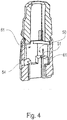
- the Fig. 4 shows a further embodiment of an insert body according to the invention with a wear protection means 60.
- an opening for example a bore 51
- a separate body 61 is mounted in the contact area 50, in which a separate body 61 is mounted.
- the position of the bore 51 and the shape and size of the separate body 61 are preferably selected such that the locking element 41 rests exclusively on the separate body 61 when the driver element 30 is inserted.
- the separate body 61 can be designed as a ball, for example, which is made of a wear-resistant material or coated with a wear-resistant material.
- an actuating handle 10 for components such as windows, doors, etc. has at least one handle 20 and a driver element 30 which can be engaged with the handle 20 in a rotationally fixed manner, with a locking device between the handle 20 and the driver element 30 40 is provided, which is designed such that the introduction of the driver element 30 into the handle 20 can be brought about in a first direction R1 and is blocked in the opposite direction R2.
- the locking device 40 has at least one locking element 41 which is acted upon by a spring force F and which can be brought into non-positive, positive and / or frictional engagement with the driver element 30, wherein the locking element 41 is designed as a locking frame that supports the driver element 30 at least in sections, and wherein the locking element 41 is pivotably mounted and is supported on a contact area 50 in the area of the handle 20.
- a wear protection means 60 is arranged or formed in the contact area 50, the blocking element 41 being supported essentially on or on the wear protection means 60 and the wear protection means 60 comprises a different material than the contact area 50.
- the wear protection means 60 consists of a wear-resistant and / or hardened material, wherein the wear protection means 60 can be a coating or a separate body 61. The latter is preferably at least partially received in a bore 51 or a recess in the contact area 50.
- the locking device 40 is designed as a preassembled structural unit in the handle 20, preferably in a handle neck 23 which has a recess 24 on the front side for receiving the locking device 40. The latter is pressed or caulked in the recess 24 in a rotationally fixed manner.
- the locking device 40 has an insert body 70, which is preferably designed as a socket 80, the locking element 41 being arranged in the socket 80 and being acted upon by the spring force F of a spring 42 which is arranged in the socket 80.
- the blocking element 41 is pressed against the wear protection means 60, which is arranged on the contact area 50, the contact area 50 being formed on the insert body 70.
- the contact area 50 is formed by an inclined surface 52 in the insert body 70, which - in a further design - is also inclined diagonally to the cross section of the driver element 30.
- the blocking element 41 rests obliquely to an axial direction A and at least at the edge on the wear protection means 50.
Landscapes
- Engineering & Computer Science (AREA)
- Mechanical Engineering (AREA)
- Lock And Its Accessories (AREA)
- Multiple-Way Valves (AREA)
- Purses, Travelling Bags, Baskets, Or Suitcases (AREA)
Description
- Die Erfindung betrifft eine Betätigungshandhabe gemäß dem Oberbegriff von Anspruch 1. Ferner betrifft die Erfindung einen Einsatzkörper für eine Betätigungshandhabe gemäß dem Oberbegriff von Anspruch 13.
- Betätigungshandhaben sind in zahlreichen Ausgestaltungen bekannt. Sie dienen beispielsweise zum Öffnen und Schließen eines Fensters, einer Tür oder dergleichen, wobei ein Handgriff meist über einen Mitnehmer, z.B. einen Vierkantstift, zur Dreh-Mitnahme einer Betätigungseinrichtung im Fenster- oder Türflügel ausgebildet ist, etwa eines Fenstergetriebes oder einer Schlossnuss.
- Neben dem Drehmoment muss der Mitnehmer gewöhnlich auch axiale Zugkräfte übertragen, z.B. bei Türbeschlägen. Die Verbindung zwischen Handgriff und Mitnehmer muss dabei so ausgebildet sein, dass beide nach der Montage axial und drehfest miteinander verankert sind, wobei - je nach Ausbildung des Fensters oder der Tür - eine Anpassung der Stiftverbindung an die jeweilige Dicke des Fensterrahmens oder des Türblatts möglich sein muss.
- Aus
EP 1 683 933 A2 ist eine Betätigungshandhabe bekannt, bei der zwischen dem Handgriff und dem Mitnehmerelement eine Vorrichtung vorgesehen ist, die eine Relativbewegung zwischen dem Handgriff und dem Mitnehmerelement in einer ersten Axialrichtung zulässt und in entgegengesetzter Axialrichtung sperrt. Dadurch ist es möglich, den Handgriff einfach auf das in das Türblatt seitlich eingesteckte und eine Schlossnuss durchragende Mitnehmerelement aufzuschieben, bis die gewünschte Einsetztiefe erreicht ist. Für die axiale Fixierung des Handgriffs entgegen der Einsteckrichtung ist in dem Handgriff eine Vorrichtung vorgesehen, die ein Sperr- oder Klemmelement aufweist, welches von einer Federkraft beaufschlagt ist und mit dem Mitnehmerelement kraft-, form- und/oder reibschlüssig in Eingriff bringbar ist. Das Sperrelement kann als Sperrrahmen ausgebildet sein, der zentrisch eine eckige Ausnehmung aufweist durch die das Mitnehmerelement geführt werden kann, sodass der Sperrrahmen das Mitnehmerelement zumindest abschnittsweise umschließt. Die Sperrwirkung wird dadurch erreicht, dass die Federkraft die Sperr-oder Klemmelemente gegen eine Anlagefläche drückt, sodass die Sperr- oder Klemmelemente in eine Schräglage gekippt werden und die Kanten der Ausnehmung der Sperr- oder Klemmelemente gegen das Mitnehmerelement drücken und damit eine axiale Bewegung des Mitnehmerelements in eine Richtung sperren. Vergleichbare Vorrichtungen sind aus derEP 2 241 704 A1 und derJP 2001 254538 A - Von Nachteil hierbei ist, dass die schwenkbar gelagerten Sperr- oder Klemmelemente direkt von der Federkraft an den Anlagebereich gedrückt werden. Wirken nach dem Einbau und einer länger andauernden, bestimmungsgemäßen Verwendung der Betätigungshandhabe, d.h. dem Öffnen und Schließen einer Tür oder eines Fensters, Kräfte auf die Sperrvorrichtung ein, kann es zu starken Abnutzungen an dem Anlagebereich der Sperr- oder Klemmelemente kommen. Die Ursache dieser Abnutzungen liegt darin, dass sich bei Einwirkung von Zug- oder Druckkräften, die Sperr- oder Klemmelemente bewegen und auf dem Anlagebereich reiben. Der daraus resultierende Verschleiß kann zu einer Verschlechterung der Sperrfunktion führen. Insbesondere kann es durch Abrieb zu einer Veränderung der Geometrie des Anlagebereichs kommen, sodass die Funktion eines Anschlags, der die für die Sperrwirkung erforderliche Schräglage der Sperr- oder Klemmelemente erst ermöglicht, nicht mehr erfüllt werden kann. Dies kann nach intensivem Gebrauch der Betätigungshandhabe zum vollständigen Versagen der Sperrverbindung zwischen dem Sperr- oder Klemmelemente und Mitnehmerelement führen. Ziel der Erfindung ist es, diese und weitere Nachteile des Standes der Technik zu überwinden und eine Betätigungshandhabe zu schaffen, die eine werkzeuglose und dauerhaft zuverlässige Verbindung zwischen Mitnehmer und Handgriff ermöglicht, wobei die Sperrwirkung auch bei längerem und sich häufig wiederholenden Gebrauch der Betätigungshandhabe dauerhaft erhalten bleibt.
- Die voranstehende Aufgabe wird gelöst durch eine Betätigungshandhabe mit den Merkmalen des unabhängigen Anspruchs 1 sowie einem Einsteckkörper für eine Betätigungshandhabe mit den Merkmalen des unabhängigen Anspruchs 13. Ausgestaltungen sind Gegenstand der Unteransprüche.
- Bei einer Betätigungshandhabe für Bauelemente wie Fenster, Türen u.dgl., mit wenigstens einem Handgriff und einem Mitnehmerelement, das drehfest mit dem Handgriff in Eingriff bringbar ist, wobei zwischen dem Handgriff und dem Mitnehmerelement eine Sperrvorrichtung vorgesehen ist, welche derart ausgebildet ist, dass das Einführen des Mitnehmerelements in den Handgriff in einer ersten Richtung bewirkbar und in entgegengesetzter Richtung gesperrt ist, wobei die Sperrvorrichtung wenigstens ein Sperrelement aufweist, welches von einer Federkraft beaufschlagt ist und das mit dem Mitnehmerelement kraft-, form- und/oder reibschlüssig in Eingriff bringbar ist, wobei das Sperrelement als Sperrrahmen ausgebildet ist, der das Mitnehmerelement zumindest abschnittsweise umschließt, und wobei das Sperrelement schwenkbar gelagert ist und sich an einem Anlagebereich im Bereich des Handgriffs abstützt, sieht die Erfindung vor, dass im Anlagebereich eine Beschichtung oder ein separater Körper aus einem verschleißfesten und/oder gehärteten Material als Verschleißschutzmittel angeordnet oder ausgebildet ist, wobei das Verschleißschutzmittel ein anderes Material als der Anlagebereich aufweist, und wobei sich das Sperrelement im Wesentlichen an oder auf dem Verschleißschutzmittel abstützt.
- Dadurch wird auf überraschend einfache und effektive Weise der Verschleiß zwischen dem wenigstens einen Sperrelement und dem Anlagebereich verhindert, weil sich das Sperrelement im Wesentlichen an oder auf dem Verschleißschutzmittel abstützen, d,h, das Sperrelement liegt zumindest teilweise oder abschnittsweise auf dem Verschleißschutzmittel auf. Letzteres bildet mithin einen Teil des Anlagebereichs, an dem das Sperrelement anliegt, und es verhindert den direkten Kontakt zwischen Sperrelement und Anlagebereich, sodass der Verschleiß des Anlagebereichs effektiv und punktgenau verhindert werden kann. Dies führt zu einer längeren Lebensdauer des Anlagebereichs sowie zum Erhalt von dessen Funktionalität und Geometrie. Die Dauerhaftigkeit der Sperrwirkung ist somit auch bei längerem und sich häufig wiederholendem Gebrauch der Betätigungshandhabe gewährleistet. Die Vorteile der einfachen und werkzeuglosen Montage sowie der einfachen Anpassbarkeit an unterschiedliche Rahmen- und Flügelstärken wird bei der erfindungsgemäßen Ausgestaltung unverändert beibehalten.
- Durch Verwendung eines von dem Material des Anlagebereichs verschiedenen verschleißfesten und/oder gehärteten Materials für das Verschleißschutzmittel können die Vorzüge zweier unterschiedlicher Materialien optimal genutzt werden. Während der Anlagebereich und die Teile, die diesen Anlagebereich bilden, kostengünstig und schnell durch Druckguss aus Metall, insbesondere durch Zinkdruckguss herstellbar sind, kann das Verschleißschutzmittel aus hochwertigeren Materialien mit besseren Verschleißschutzeigenschaften gewählt werden.
- Bei gehärteten Materialien wird dabei durch gezielte Änderung und Umwandlung seines Gefüges eine Festigkeitssteigerung erreicht. Diese Festigkeitssteigerung bringt eine höhere Verschleißbeständigkeit mit sich, sodass ein solches Material, insbesondere ein gehärtes Metall, wie beispielsweise gehärteter Stahl, besonders effektiv als Verschleißschutzmittel eingesetzt werden kann.
- Grundsätzlich kommen aber auch andere verschleißfeste Hartstoffe als Material für das erfindungsgemäße Verschleißschutzmittel in Frage. Hierzu gehören metallische Hartstoffe wie Carbide, Nitride, Carbonitride, Boride und Silicide der Übergangsmetalle, Hartstoff-Mischkristalle (z. B. TiC-WC, TiC-TaC-WC, TiC-TiN), Doppelcarbide und Komplexcarbide (z. B. Co3W3C, Ni3W3C) und intermetallische Verbindungen (z.B. W-Co, W-Os, W-Re, W-Ir, Mo-Be). Als nichtmetallische Hartstoffe kommen Carbide, Nitride und Oxide von Hauptgruppenelementen und einige Modifikationen der reinen Elemente, wie natürlicher und synthetischer Diamant, Korund (Al2O3), natürliche und synthetische Edel- und Halbedelsteine (z.B. Saphir, Rubin, Zirkon), Bor, Borcarbid (B4C), kubisches Bornitrid (BN, "Borazon"), Berylliumcarbid, Siliciumcarbid (SiC), Siliciumnitrid (Si3N4) sowie Aluminiumnitrid (AIN) in Frage.
Auch denkbar sind Kompositmaterialien mit hoher Verschleißfestigkeit, die aus mehr als nur einem Material bestehen. - Für die Verwendung einer Beschichtung als Verschleißschutzmittel sind als verschleißfeste Beschichtungen unter anderem Metall-Legierungen bekannt. Diese Legierungen werden durch Spritzen oder Schweißen auf den Basiskörper aufgetragen und haften auf diesem durch Verschmelzen, durch Adhäsion oder durch Bildung einer Zwischenschicht. Auch ein Aufbringen der Beschichtung durch Lackieren ist denkbar. Der Vorteil der Beschichtung liegt darin, dass sich die Beschichtung über die ganze Anlagefläche erstrecken kann und somit seine Verschleißschutzeigenschaft auf die gesamte beanspruchte Fläche ausgedehnt wird. Außerdem muss im Falle einer Beschichtung kein zusätzlicher räumlicher Körper in die Vorrichtung eingebracht werden, was die Fertigung und Montage erleichtert.
- Bei Verwendung eines separaten Körpers als Verschleißschutzmittel, stützt sich das Sperrelement im Wesentlichen an diesem separaten Körper ab, sodass der direkte Kontakt zwischen dem Sperrelement und dem Anlagebereich vermieden wird und keine Abnutzung des Anlagebereichs erfolgen kann. Der Körper kann mit dem Anlagebereich, insbesondere durch kleben oder schweißen verbunden sein, sodass eine belastbare Verbindung zwischen dem Körper und dem Verschleißschutzmittel erreicht werden kann.
- Gemäß einer anderen Ausführungsform ist das Verschleißschutzmittel ein separater Körper, welcher in einer Bohrung im Anlagebereich zumindest teilweise aufgenommen ist. Durch die Anordnung der Bohrung lässt sich die Anordnung des Verschleißschutzmittels festlegen. Hierdurch lässt sich der Einbau des Verschleißschutzmittels relativ leicht durchführen, gleichermaßen können beschädigte Verschleißschutzmittel auf einfache Art und Weise ausgetauscht werden. Soll das Verschleißschutzmittel unlösbar befestigt werden, könnte dies beispielsweise mittels heiß-isostatischen Pressen mit dem Anlagebereich erreicht werden.
- Dabei hat es sich als vorteilhaft erwiesen, wenn das Verschleißschutzmittel als ein separater, rotationssymmetrischer, insbesondere walzenförmiger oder kugelsymmetrischer Körper ausgebildet ist. Das Sperrelement hat somit keinen oder nur einen geringen Kontakt zu dem meist aus Zamak-Legierung im Zinkdruckgussverfahren hergestellten und somit wenig verschleißfesten Anlagebereich, sodass eine Abnutzung der Anlagefläche vermieden wird. Zudem hat ein kugelförmiger Körper als Verschleißschutzmittel den Vorteil, dass dieser nur eine geringe Berührungsfläche für das Sperrelement bietet.
- Gemäß einer weiteren Ausgestaltung ist die Sperrvorrichtung im Griffhals ausgebildet. Durch eine solche Ausgestaltung reduziert sich die Zahl der unterschiedlichen Bauteile, da keine zusätzlichen Führungselemente vorgesehen werden müssen. Dies reduziert den Montageaufwand und die Herstellungskosten für die Betätigungshandhabe. Des Weiteren hat es sich als vorteilhaft erwiesen, wenn der Handgriff einen Griff-Hauptteil und einen Griffhals aufweist, wobei der Griffhals stirnseitig eine Ausnehmung aufweist und die Sperrvorrichtung in der Ausnehmung ausgebildet ist. Besonders vorteilhaft, ist in die Ausnehmung stirnseitig ein Einsatzkörper eingesetzt, wobei das Sperrelement von der Federkraft einer Feder, die sich im Griffhals abstützt, gegen das Verschleißschutzmittel, welches am Anlagebereich angeordnet ist, gedrückt wird. Besonders vorteilhaft ist es wenn der Anlagebereich am Einsatzkörper ausgebildet ist.
- In einer speziellen Ausführungsvariante ist der Einsatzkörper als Buchse ausgebildet, die in der Ausnehmung im Griffhals eingesetzt ist, wobei das Sperrelement in der Buchse angeordnet ist und das Sperrelement von der Federkraft einer Feder, die in der Buchse angeordnet ist beaufschlagt wird. Der Einsatzköper mit der Sperrvorrichtung kann hierdurch als vormontierte Einheit ausgebildet werden. Diese Einheit kann dann einfach in den Griffhals des Handgriffs eingeschraubt, eingeklebt oder eingepresst werden. Dies vereinfacht nicht nur die Lagerhaltung sondern kann je nach Kundenwunsch werkseitig in jedem beliebigen Tür- oder Fenstergriff vorgesehen werden.
- Gemäß einer weiteren Ausgestaltung wird der Anlagebereich von einer Schrägfläche des Einsatzkörpers gebildet. Dabei ist es besonders vorteilhaft, wenn die Neigungsrichtung der Schrägfläche diagonal zum Querschnitt des Mitnehmerelements verläuft. Die schräge Fläche sorgt dafür, dass das Sperrelement stets einen maximal großen Hebelarm bildet. Zudem wird in diesem Fall keine gesonderte Stützkante als Drehachse benötigt, sodass die Herstellung des Sperrelements schnell und kostengünstig, insbesondere durch Stanzen erfolgen kann.
- In einer weiteren Ausführungsform liegt das Sperrelement schräg zur Axialrichtung und liegt zumindest randseitig am Verschleißschutzmittel an. Auf diese Weise lässt sich bei gleichbleibender Sperrwirkung die Kontaktfläche zwischen Verschleißschutzmittel und Sperrelement zusätzlich verringern. Die Abriebkräfte wirken so nur auf eine besonders kleine, nahezu punktförmige Fläche des Verschleißschutzmittels ein.
- Des Weiteren betrifft die Erfindung einen Einsatzkörper für eine Betätigungshandhabe, die in einem Griffhals der Betätigungshandhabe fixiert oder fixierbar ist, wobei der Einsatzkörper als Buchse ausgebildet ist, die stirnseitig in den Griffhals einer Betätigungshandhabe einsteckbar ist, wobei in dem Einsatzkörper eine Sperrvorrichtung ausgebildet ist, die wenigstens ein Sperrelement aufweist, welches von einer Federkraft beaufschlagt ist und wobei das Sperrelement als Sperrrahmen ausgebildet ist und das Sperrelement schwenkbar gelagert ist und sich an einem Anlagebereich im Innenraum der Buchse abstützt, wobei erfindungsgemäß im Anlagebereich ein Verschleißschutzmittel angeordnet ist, wobei sich das Sperrelement im Wesentlichen an oder auf dem Verschleißschutzmittel abstützt.
- Das Verschleißschutzmittel bildet einen Teil des Anlagebereichs an dem das Sperrelement anliegt. Das Verschleißschutzmittel verhindert den direkten Kontakt zwischen Sperrelement und Anlagebereich, sodass ein Verschleiß des Anlagebereichs effektiv und punktgenau verhindert werden kann. Dies führt zu einer längeren Lebensdauer des Anlagebereichs sowie zum Erhalt dessen Funktionalität. Die Dauerhaftigkeit der Sperrwirkung ist somit auch bei längerem und sich häufig wiederholendem Gebrauch der Betätigungshandhabe gewährleistet. Gleichzeitig kann der Einsatzkörper als vorgekapselte Einheit vorgefertigt werden. Ein derartig als Buchse ausgebildete Einsatzkörper kann als eigenständiges Bauteil hergestellt und problemlos mit Handgriffen kombiniert werden, um eine Betätigungshandhabe zu bilden. Die Einheit kann dann einfach in den Griffhals des Handgriffs eingeschraubt, eingeklebt oder eingepresst werden. Ein solcher Einsatzkörper vereinfacht nicht nur die Lagerhaltung sondern kann je nach Kundenwunsch werkseitig in jedem beliebigen Tür- oder Fenstergriff vorgesehen werden.
- In einer vorteilhaften Ausgestaltung, weist das Verschleißschutzmittel ein anderes Material als der Anlagebereich auf. Hierdurch können die Vorzüge zweier unterschiedlicher Materialien optimal genutzt werden. Während der Anlagebereich und die Teile, die diesen Anlagebereich bilden, kostengünstig und schnell durch Druckguss aus Metall, insbesondere durch Zinkdruckguss herstellbar sind, kann das Verschleißschutzmittel aus hochwertigeren Materialien mit besseren Verschleißschutzeigenschaften gewählt werden.
- Hierbei kann das Verschleißschutzmittel besonders vorteilhaft aus einem gehärteten Material und/oder verschleißfesten Material bestehen. Bei gehärteten Materialien wird durch gezielte Änderung und Umwandlung seines Gefüges eine Festigkeitssteigerung erreicht. Diese Festigkeitssteigerung bringt eine höhere Verschleißbeständigkeit mit sich, sodass ein solches Material, insbesondere ein gehärtes Metall, wie beispielsweise gehärteter Stahl, besonders effektiv als Verschleißschutzmittel eingesetzt werden kann.
- Grundsätzlich kommen aber auch andere verschleißfeste Hartstoffe als Material für das erfindungsgemäße Verschleißschutzmittel in Frage. Hierzu gehören metallische Hartstoffe wie Carbide, Nitride, Carbonitride, Boride und Silicide der Übergangsmetalle, Hartstoff-Mischkristalle (z. B. TiC-WC, TiC-TaC-WC, TiC-TiN), Doppelcarbide und Komplexcarbide (z. B. Co3W3C, Ni3W3C) und intermetallische Verbindungen (z.B. W-Co, W-Os, W-Re, W-Ir, Mo-Be). Als nichtmetallische Hartstoffe kommen Carbide, Nitride und Oxide von Hauptgruppenelementen und einige Modifikationen der reinen Elemente, wie natürlicher und synthetischer Diamant, Korund (AI2O3), natürliche und synthetische Edel- und Halbedelsteine (z.B. Saphir, Rubin, Zirkon), Bor, Borcarbid (B4C), kubisches Bornitrid (BN, "Borazon"), Berylliumcarbid, Siliciumcarbid (SiC), Siliciumnitrid (Si3N4) sowie Aluminiumnitrid (AIN) in Frage.
Auch denkbar sind Kompositmaterialien mit hoher Verschleißfestigkeit, die aus mehr als nur einem Material bestehen. - Gemäß einer weiteren Ausführungsform ist das Verschleißschutzmittel eine Beschichtung. Als verschleißfeste Beschichtungen sind unter anderem Metall-Legierungen bekannt. Diese Legierungen werden durch Spritzen oder Schweißen auf den Basiskörper aufgetragen und haften auf diesem durch ein Verschmelzen, durch Adhäsion oder durch Bildung einer Zwischenschicht. Auch ein Auftragen der Beschichtung durch Lackieren ist denkbar. Der Vorteil der Beschichtung liegt darin, dass sich die Beschichtung über die ganze Anlagefläche erstrecken kann und somit seine Verschleißschutzeigenschaft auf die gesamte beanspruchte Fläche ausgedehnt wird. Außerdem muss im Falle einer Beschichtung kein zusätzlicher räumlicher Körper in die Vorrichtung eingebracht werden, was die Fertigung und Montage erleichtert.
- In einer Ausführungsform ist das Verschleißschutzmittel ein separater Körper. Das Sperrelement stützt sich im Wesentlichen an diesem separaten Körper ab, sodass der direkte Kontakt zwischen dem Sperrelement und dem Anlagebereich vermieden wird und keine Abnutzung des Anlagebereichs erfolgen kann. Der Körper kann mit dem Anlagebereich, insbesondere durch kleben oder schweißen verbunden sein, sodass eine belastbare Verbindung zwischen dem Körper und dem Verschleißschutzmittel erreicht werden kann.
- Gemäß einer anderen Ausführungsform ist das Verschleißschutzmittel ein separater Körper, welcher in einer Bohrung im Anlagebereich zumindest teilweise aufgenommen ist. Durch die Anordnung der Bohrung lässt sich die Anordnung des Verschleißschutzmittels festlegen. Hierdurch lässt sich der Einbau des Verschleißschutzmittels relativ leicht durchführen, gleichermaßen können beschädigte Verschleißschutzmittel auf einfache Art und Weise ausgetauscht werden. Soll das Verschleißschutzmittel unlösbar befestigt werden, könnte dies beispielsweise mittels heiß-isostatischen Pressen mit dem Anlagebereich erreicht werden. Dabei hat es sich als vorteilhaft erwiesen, wenn das Verschleißschutzmittel als ein separater, rotationssymmetrischer, insbesondere walzenförmiger oder kugelsymmetrischer Körper ausgebildet ist. Das Sperrelement hat somit keinen oder nur einen geringen Kontakt zu dem meist aus Zamak-Legierung im Zinkdruckgussverfahren hergestellten und somit wenig verschleißfesten Anlagebereich, sodass eine Abnutzung der Anlagefläche vermieden wird. Zudem hat ein kugelförmiger Körper als Verschleißschutzmittel den Vorteil, dass dieser nur eine geringe Berührungsfläche für das Sperrelement bietet.
- Gemäß einer weiteren Ausgestaltung ist das Sperrelement in der Buchse angeordnet und das Sperrelement wird von der Federkraft einer Feder, die in der Buchse angeordnet ist, beaufschlagt. Dabei ist es insbesondere von Vorteil, wenn der Anlagebereich von einer Schrägfläche im Innenraum der Buchse gebildet wird.
- In einer weiteren Ausführungsform liegt das Sperrelement schräg zur Axialrichtung und liegt zumindest randseitig am Verschleißschutzmittel an. Auf diese Weise lässt sich bei gleichbleibender Sperrwirkung die Kontaktfläche zwischen Verschleißschutzmittel und Sperrelement zusätzlich verringern. Die Abriebkräfte wirken so nur auf eine besonders kleine, nahezu punktförmige Fläche des Verschleißschutzmittels ein.
- Weitere Merkmale, Einzelheiten und Vorteile der Erfindung ergeben sich aus dem Wortlaut der Ansprüche sowie aus der folgenden Beschreibung von Ausführungsbeispielen anhand der Zeichnungen. Es zeigen:
- Fig. 1
- eine schematische Darstellung einer Betätigungshandhabe mit einer eingesetzten Sperrvorrichtung;
- Fig. 2
- einen Längsschnitt eines Einsatzkörpers mit einer Sperrvorrichtung und eingesetztem Mitnehmerelement;
- Fig. 3
- einen Längsschnitt durch einen Einsatzkörper ohne Sperrvorrichtung und Mitnehmerelement; und
- Fig. 4
- einen Längsschnitt durch einen Einsatzkörper mit einem separaten Körper zur einseitigen Lagerung des Sperrelements.
- Im Folgenden werden einander ähnliche oder identische Elemente mit den gleichen Bezugszeichen gekennzeichnet.
-
Fig. 1 zeigt eine schematische Darstellung einer Betätigungshandhabe 10, wie sie beispielsweise als Türgriff zum Öffnen und Schließen von Türen Verwendung findet. Im Wesentlichen besteht die Betätigungshandhabe 10 aus einem Griff-Hauptteil 22, welcher beispielsweise bei einer Verwendung als Türgarnitur oder Türbeschlag mit einer gegengleichen Handhabe auf der gegenüberliegenden Seite eines Türblattes über ein Mitnehmerelement 30 verbunden werden kann. Das Mitnehmerelement 30 ist dabei in seinem Querschnitt rechteckig oder quadratisch ausgeführt und in eine entsprechende Aufnahme im Griff-Hauptteil 22 einsetzbar, sodass sich bei Betätigung des Griff-Hauptteils 22 auf einer Seite des Türblattes der gegengleiche Griff-Hauptteil 22 auf der gegenüberliegenden Seite des Türblattes synchron mitbewegt. Das Mitnehmerelement, auch Vierkantstift genannt, durchsetzt üblicherweise eine Schlossnuss in einem Türschloss, das stirnseitig in das Türblatt eingesetzt ist. - Der Griff-Hauptteil 22 ist - wie
Fig. 1 zeigt - in den Handgriff 20, welcher bei einer Betätigung der Handhabe gewöhnlich von der Hand des Bedieners gegriffen wird, und einen Griffhals unterteilt. In der inFig. 1 dargestellten Ausführungsform ist der Griffhals 23 rechtwinklig zu dem Handgriff 20 angeordnet. Zur Montage der dargestellten Betätigungshandhabe 10 in einer Tür oder einem Fenster wird zunächst das Mitnehmerelement 30 in eine entsprechende Aufnahme des Griffhalses entlang einer ersten Verschiebungsrichtung R1 eingeführt. Anschließend wird das Mitnehmerelement 30 durch eine entsprechende Ausnehmung aus dem Türblatt oder dem Fensterrahmen geführt und auf der gegenüberliegenden Seite ebenfalls in den Griffhals 23 eines gegenstückigen Griff-Hauptteils eingeführt. - Erfindungsgemäß ist dabei vorgesehen, dass das Mitnehmerelement 30 zwar entlang einer ersten Richtung R1 in den Griffhals 23 des Griff-Hauptteils eingeführt, jedoch anschließend nicht ohne Einsatz von entsprechenden Werkzeugen entlang einer der ersten Richtung R1 entgegengesetzten Richtung R2 wieder aus dem Griffhals 23 entfernt werden kann. Hierzu ist erfindungsgemäß eine Sperrvorrichtung 40 vorgesehen, welche in einem Einsatzkörper 70 angeordnet ist. Der Einsatzkörper 70 ist wiederum in eine entsprechende Ausnehmung aus dem Griffhals 23 eingesetzt und beispielsweise durch einpressen in dem Griffhals 23 dauerhaft befestigt.
- Die
Fig. 2 zeigt einen Längsschnitt durch einen solchen Einsatzkörper 70, welcher beispielsweise in einem Druckgussverfahren aus Zinkdruckguss hergestellt werden kann. Wie in derFig. 2 zu erkennen ist, ist der Einsatzkörper 70 als Buchse 80 ausgeführt, welche in eine entsprechende Ausnehmung 24 des Griffhalses 23 eingesetzt werden kann. Durch den Innenbereich der Buchse 80 wird eine Führung gebildet, in welche das Mitnehmerelement 30 bei einer Montage des Griff-Hauptteils 22 eingeführt werden kann. Ferner ist innerhalb der Buchse 80 eine Ausnehmung vorgesehen, in der die Sperrvorrichtung 40 vorgesehen ist. Die Sperrvorrichtung 40 setzt sich dabei aus einem Sperrelement 41 und einem Rückstellelement, bzw. einer Feder 42 zusammen. Die Feder 42 ist dabei an einem Anschlag der Buchse 80 derart angeordnet, dass die Feder 42 bei einer Kompression eine Kraft F auf das Sperrelement 41 in Richtung R2 ausübt. Das Sperrelement 41 ist wiederum als scheibenförmiges Element mit einer Ausnehmung ausgeführt, wobei die Form der Ausnehmung der Querschnittsform des Mitnehmerelements 30 entspricht. Dabei ist vorgesehen, dass die Ausnehmung in ihren Dimensionen so gestaltet ist, dass bei einem Einführen des Mitnehmerelements 30 in die Ausnehmung zwischen dem Mitnehmerelement 30 und den Wandungen der Ausnehmung ein Luftspalt verbleibt, sodass ein transversales Spiel des Mitnehmerelements 30 gegenüber dem Sperrelement 41 verbleibt. - Die sperrende Wirkung eines solchen Sperrelements in Verbindung mit der Feder 42 und der speziellen Ausgestaltung der Ausnehmung innerhalb des als Buchse 80 ausgeführten Einsatzkörpers wird aus der Zusammenschau der
Fig. 2 und3 ersichtlich. - Die
Fig. 3 zeigt den Einsatzkörper derFig. 2 ohne ein in den Einsatzkörper 70 eingesetztes Sperrelement 41, Mitnehmerelement 30 und ohne die Feder 42 in einem Längsschnitt. Gut erkennbar ist erneut die Ausnehmung in welche das Mitnehmerelement 30 eingeführt werden kann, sowie die Aussparung (im Folgenden als Innenraum 81 bezeichnet), welche zur Aufnahme der Sperrvorrichtung 40 ausgebildet ist. Der Innenraum 81 wird in axialer Richtung des Einsatzkörpers 70 einerseits durch die Auflagefläche 53 begrenzt, welche zur Lagerung der Feder 42 vorgesehen ist. Andererseits wird der Innenraum 81 in der entgegengesetzten axialen Richtung durch eine Schrägfläche 52 begrenzt, welche gegenüber einer zur Längsachse L des Einsatzkörpers 70 senkrechten Ebene um einen Winkel α verkippt ist. Dabei erstreckt sich die Richtung der Verkippung vorzugsweise entlang einer Diagonalen des Querschnitts der Ausnehmung für das Mitnehmerelement 30. Nach einsetzen der Feder 42 und dem Sperrelement 41, welches in der inFig. 2 dargestellten Ausführungsform aus zwei separaten Scheiben zusammengesetzt ist, bewirkt die Feder 42 eine Kraft F auf die Scheiben des Sperrelements 41, sodass das Sperrelement 41 auf die Schrägfläche 52 gedrückt wird. Dabei ist der Winkel α um den die Schrägfläche 52 gekippt ist vorzugsweise so gewählt, dass die Projektion der Öffnung des Sperrelements 41 in der Ebene senkrecht zur Längsrichtung L des Einsatzkörpers 70 in zumindest einer Richtung kleiner ist, als der Querschnitt des Mitnehmerelements 30. - Wird nun das Mitnehmerelement 30 entlang der in
Fig. 1 dargestellten Richtung R1 in die entsprechende Ausnehmung des Einsatzkörpers 70 eingeführt, übt das Mitnehmerelement 30 so lange eine Kraft gegen die Richtung der Federkraft F auf das Sperrelement 41 aus, bis das Sperrelement 41 soweit verkippt wurde, dass das Mitnehmerelement 30 durch die Öffnung des Sperrelements 41 hindurchgeführt werden kann. Dabei liegt das Sperrelement üblicherweise nur noch an dem als Anlagebereich 50 bezeichneten Bereich der Schrägfläche 52 auf. Wird nun nach dem Einführen des Mitnehmerelements 30 in die Öffnung des Sperrelements 41 entlang der Richtung R1 das Mitnehmerelement 30 in eine der Richtung R1 entgegengesetzte Richtung R2 bewegt, bewirkt die Feder 42 ein Verkippen des Sperrelements 41 um eine Achse, welche durch den Auflagepunkt des Sperrelements 41 auf dem Anlagebereich 50 des Innenraums 81 definiert ist. Hierdurch verkantet sich das Sperrelement 41 mit dem Mitnehmerelement 30, sodass ein herausziehen des Mitnehmerelements 30 aus dem Einsatzkörper 70 effektiv verhindert wird. - Um das Mitnehmerelement 30 dennoch aus dem Einsatzkörper 70 herausziehen zu können, ist an dem Einsatzkörper 70 eine seitliche Öffnung 54 vorgesehen. Mittels eines geeigneten Werkzeugs ist es damit möglich durch die Öffnung 54 eine Kraft auf das Sperrelement 41 entgegen der Richtung der Federkraft F auszuüben, sodass das Sperrelement 41 so weit verkippt wird, dass das Sperrelement 41 nicht mehr mit dem Mitnehmerelement 30 verkantet ist.
- Wie zuvor bereits beschrieben wurde, liegt das Sperrelement 41 bei einem eingesetzten Mitnehmerelement 30 im Wesentlichen auf dem Anlagebereich 50 des Innenraums 81 auf. Dabei bewirkt die Feder 42 dauerhaft eine Kraft auf das Sperrelement 41, welche das Sperrelement 41 auf die Fläche des Anlagebereichs 50 presst. Da es während des Einführens eines Mitnehmerelements 30 in den Einsatzkörper 70, wie auch im Betrieb der Betätigungshandhabe 10 mit einem eingesetzten Einsatzkörper 70 fortwährend zu leichten Lageveränderungen des Sperrelements 41 auf dem Anlagebereich 50 kommt, bewirkt die hierbei entstehende Reibung eine Abnutzung des Materials des Anlagebereichs 50. Um dem Verschleiß des Anlagebereichs 50 entgegenzuwirken ist erfindungsgemäß ein Verschleißschutzmittel 60 vorgesehen. Bei dem Verschleißschutzmittel 60 kann es sich beispielsweise um eine Beschichtung mit einem verschleißfesten Hartstoff, oder um ein zusätzliches auf der entsprechenden Oberfläche des Einsatzkörpers 70 angebrachtes Element aus einem verschleißfesten Werkstoff wie beispielsweise gehärtetem Stahl handeln.
- Durch die Verwendung eines solchen Verschleißschutzmittels 60 könnten Abnutzungserscheinung im Bereich des Anlagebereichs des Sperrelements 41 effektiv vermieden werden.
- Die
Fig. 4 zeigt eine weitere Ausführungsform eines erfindungsgemäßen Einsatzkörpers mit einem Verschleißschutzmittel 60. Dabei ist in dem Anlagebereich 50 eine Öffnung, beispielsweise eine Bohrung 51 vorgesehen, in welcher ein separater Körper 61 gelagert ist. Dabei ist die Position der Bohrung 51, sowie die Form und Größe des separaten Körpers 61vorzugsweise so gewählt, dass das Sperrelement 41 bei einem eingesetzten Mitnehmerelement 30 ausschließlich auf dem separaten Körper 61 aufliegt. Dabei kann der separate Körper 61 beispielsweise als Kugel ausgeführt sein, welche aus einem verschleißfesten Material gefertigt oder mit einem verschleißfesten Material beschichtet ist. - Die Erfindung ist nicht auf eine der vorbeschriebenen Ausführungsformen beschränkt, sondern in vielfältiger Weise abwandelbar. Man erkennt, dass eine Betätigungshandhabe 10 für Bauelemente wie Fenster, Türen u.dgl., wenigstens einem Handgriff 20 und ein Mitnehmerelement 30 hat, das drehfest mit dem Handgriff 20 in Eingriff bringbar ist, wobei zwischen dem Handgriff 20 und dem Mitnehmerelement 30 eine Sperrvorrichtung 40 vorgesehen ist, welche derart ausgebildet ist, dass das Einführen des Mitnehmerelements 30 in den Handgriff 20 in einer ersten Richtung R1 bewirkbar und in entgegengesetzter Richtung R2 gesperrt ist. Die Sperrvorrichtung 40 hat hierzu wenigstens ein Sperrelement 41, welches von einer Federkraft F beaufschlagt ist und das mit dem Mitnehmerelement 30 kraft-, form- und/oder reibschlüssig in Eingriff bringbar ist, wobei das Sperrelement 41 als Sperrrahmen ausgebildet ist, der das Mitnehmerelement 30 zumindest abschnittsweise umschließt, und wobei das Sperrelement 41 schwenkbar gelagert ist und sich an einem Anlagebereich 50 im Bereich des Handgriffs 20 abstützt. Um den Verschleiß zwischen dem Sperrelement 41 und dem Anlagebereich 50 zu vermindern, sieht die Erfindung vor, dass im Anlagebereich 50 ein Verschleißschutzmittel 60 angeordnet oder ausgebildet ist, wobei sich das Sperrelement 41 im Wesentlichen an oder auf dem Verschleißschutzmittel 60 abstützt und wobei das Verschleißschutzmittel 60 ein anderes Material aufweist als der Anlagebereich 50. Bevorzugt besteht das Verschleißschutzmittel 60 aus einem verschleißfesten und/oder gehärteten Material, wobei das Verschleißschutzmittel 60 eine Beschichtung oder ein separater Körper 61 sein kann. Letzterer ist bevorzugt in einer Bohrung 51 oder einer Ausnehmung im Anlagebereich 50 zumindest teilweise aufgenommen.
- Die Sperrvorrichtung 40 ist als vormontierte Baueinheit im Handgriff 20 ausgebildet, vorzugsweise in einem Griffhals 23, der stirnseitig eine Ausnehmung 24 für die Aufnahme der Sperrvorrichtung 40 aufweist. Letztere ist in der Ausnehmung 24 drehfest verpresst oder verstemmt. Die Sperrvorrichtung 40 hat dazu einen Einsatzkörper 70, der vorzugsweise als Buchse 80 ausgebildet ist, wobei das Sperrelement 41 in der Buchse 80 angeordnet ist und von der Federkraft F einer Feder 42, die in der Buchse 80 angeordnet ist, beaufschlagt wird. Dadurch wird das Sperrelement 41 gegen das Verschleißschutzmittel 60, welches am Anlagebereich 50 angeordnet ist, gepresst, wobei der Anlagebereich 50 am Einsatzkörper 70 ausgebildet ist. Um die Klemmkraft der Sperrvorrichtung 40 zu erhöhen, ist der Anlagebereich 50 von einer Schrägfläche 52 im Einsatzkörper 70 gebildet, die - in einer weiteren Bauform - zudem diagonal zum Querschnitt des Mitnehmerelements 30 geneigt ist. Dabei liegt das Sperrelement 41 schräg zu einer Axialrichtung A und zumindest randseitig am Verschleißschutzmittel 50 an.
-
- F
- Federkraft
- R1
- erste Richtung
- R2
- zweite Richtung
- L
- Längsachse
- A
- Axialrichtung
- 10
- Betätigungshandhabe
- 20
- Handgriff
- 22
- Griff-Hauptteil
- 23
- Griffhals
- 24
- Ausnehmung
- 30
- Mitnehmerelement
- 40
- Sperrvorrichtung
- 41
- Sperrelement
- 42
- Feder
- 50
- Anlagebereich
- 51
- Bohrung
- 52
- Schrägfläche
- 53
- Auflagefläche
- 54
- Öffnung
- 60
- Verschleißschutzmittel
- 61
- Körper
- 70
- Einsatzkörper
- 80
- Buchse
- 81
- Innenraum
Claims (10)
- Betätigungshandhabe (10) für Bauelemente wie Fenster, Türen u.dgl., mit wenigstens einem Handgriff (20) und einem Mitnehmerelement (30), das drehfest mit dem Handgriff (20) in Eingriff bringbar ist, wobei zwischen dem Handgriff (20) und dem Mitnehmerelement (30) eine Sperrvorrichtung (40) vorgesehen ist, welche derart ausgebildet ist, dass das Einführen des Mitnehmerelements (30) in den Handgriff (20) in einer ersten Richtung (R1) bewirkbar und in entgegengesetzter Richtung (R2) gesperrt ist, wobei die Sperrvorrichtung (40) wenigstens ein Sperrelement (41) aufweist, welches von einer Federkraft (F) beaufschlagt ist und das mit dem Mitnehmerelement (30) kraft-, form- und/oder reibschlüssig in Eingriff bringbar ist, wobei das Sperrelement (41) als Sperrrahmen ausgebildet ist, der das Mitnehmerelement (30) zumindest abschnittsweise umschließt, und wobei das Sperrelement schwenkbar gelagert ist und sich an einem Anlagebereich (50) im Bereich des Handgriffs (20) abstützt, dadurch gekennzeichnet, dass im Anlagebereich (50) eine Beschichtung oder ein separater Körper (61) aus einem verschleißfesten und/oder gehärteten Material als Verschleißschutzmittel (60) angeordnet oder ausgebildet ist, wobei das Verschleißschutzmittel (60) ein anderes Material als der Anlagebereich (50) aufweist, und wobei sich das Sperrelement (41) im Wesentlichen an oder auf dem Verschleißschutzmittel (60) abstützt.
- Betätigungshandhabe (10) nach Anspruch 1, dadurch gekennzeichnet, dass das Verschleißschutzmittel (60) ein separater Körper (61) ist, welcher in einer Bohrung (51) im Anlagebereich (50) zumindest teilweise aufgenommen ist.
- Betätigungshandhabe (10) nach einem der vorhergehenden Ansprüche, dadurch gekennzeichnet, dass die Sperrvorrichtung (40) im Handgriff (20) ausgebildet ist.
- Betätigungshandhabe (10) nach einem der vorhergehenden Ansprüche, dadurch gekennzeichnet, dass der Handgriff (20) einen Griff-Hauptteil (22) und einen Griffhals (23) aufweist, wobei der Griffhals (23) stirnseitig eine Ausnehmung (24) aufweist und die Sperrvorrichtung (40) in der Ausnehmung (24) ausgebildet ist.
- Betätigungshandhabe (10) nach Anspruch 4, dadurch gekennzeichnet, dass in die Ausnehmung (24) stirnseitig ein Einsatzkörper (70) eingesetzt ist, wobei das Sperrelement (41) von der Federkraft (F) einer Feder (42), die sich im Griffhals (23) abstützt, gegen das Verschleißschutzmittel (60), welches am Anlagebereich (50) angeordnet ist, gedrückt wird, wobei der Anlagebereich (50) am Einsatzkörper (70) ausgebildet ist.
- Betätigungshandhabe (10) nach Anspruch 5, dadurch gekennzeichnet, dass der Einsatzkörper (70) als Buchse (80) ausgebildet ist, die in der Ausnehmung (24) im Griffhals (23) eingesetzt ist, wobei das Sperrelement (41) in der Buchse (80) angeordnet ist und von der Federkraft (F) einer Feder (42), die in der Buchse (80) angeordnet ist, beaufschlagt wird.
- Betätigungshandhabe (10) nach einem der Ansprüche 4 bis 6, dadurch gekennzeichnet, dass der Anlagebereich (50) von einer Schrägfläche (52) des Einsatzkörpers (70) gebildet wird.
- Betätigungshandhabe (10) nach Anspruch 7, dadurch gekennzeichnet, dass eine Neigungsrichtung der Schrägfläche (52) diagonal zum Querschnitt des Mitnehmerelements (30) verläuft.
- Betätigungshandhabe (10) nach einem der vorhergehenden Ansprüche, dadurch gekennzeichnet, dass das Sperrelement (41) schräg zu einer Axialrichtung (A) liegt und zumindest randseitig am Verschleißschutzmittel (50) anliegt.
- Einsatzkörper (70) für eine Betätigungshandhabe (10), die in einem Griffhals (23) der Betätigungshandhabe (10) fixiert oder fixierbar ist, wobei der Einsatzkörper (70) als Buchse (80) ausgebildet ist, die stirnseitig in den Griffhals(23) einer Betätigungshandhabe (10) einsteckbar ist, wobei in dem Einsatzkörper (70) eine Sperrvorrichtung (40) ausgebildet ist, für ein Mitnehmerelement (30), das drehfest mit dem Betätigungshandhabe in Eingriff bringbar ist, welche derart ausgebildet ist, dass das Einführen des Mitnehmerelements (30) in die Betätigungshandhabe in einer ersten Richtung (R1) bewirkbar und in entgegengesetzter Richtung (R2) gesperrt ist, wobei die Sperrvorrichtung wenigstens ein Sperrelement (41) aufweist, welches von einer Federkraft (F) beaufschlagt ist, wobei das Sperrelement (41) als Sperrrahmen ausgebildet ist, und wobei das Sperrelement (41) schwenkbar gelagert ist und sich an einem Anlagebereich (50) im Innenraum (81) der Buchse (80) abstützt, dadurch gekennzeichnet, dass im Anlagebereich (50) eine Beschichtung oder ein separater Körper (61) aus einem verschleißfesten und/oder gehärteten Material als Verschleißschutzmittel (60) angeordnet ist, das ein anderes Material als der Anlagebereich (50) aufweist, wobei sich das Sperrelement (41) im Wesentlichen an oder auf dem Verschleißschutzmittel (60) abstützt.
Priority Applications (1)
| Application Number | Priority Date | Filing Date | Title |
|---|---|---|---|
| PL17152823T PL3202999T3 (pl) | 2016-02-04 | 2017-01-24 | Uchwyt uruchamiający oraz wkładka do uchwytu uruchamiającego |
Applications Claiming Priority (1)
| Application Number | Priority Date | Filing Date | Title |
|---|---|---|---|
| DE102016102013.3A DE102016102013A1 (de) | 2016-02-04 | 2016-02-04 | Betätigungshandhabe und Einsatzkörper für eine Betätigungshandhabe |
Publications (2)
| Publication Number | Publication Date |
|---|---|
| EP3202999A1 EP3202999A1 (de) | 2017-08-09 |
| EP3202999B1 true EP3202999B1 (de) | 2020-08-26 |
Family
ID=57890692
Family Applications (1)
| Application Number | Title | Priority Date | Filing Date |
|---|---|---|---|
| EP17152823.5A Active EP3202999B1 (de) | 2016-02-04 | 2017-01-24 | Betätigungshandhabe und einsatzkörper für eine betätigungshandhabe |
Country Status (7)
| Country | Link |
|---|---|
| EP (1) | EP3202999B1 (de) |
| CN (1) | CN107035228A (de) |
| DE (1) | DE102016102013A1 (de) |
| ES (1) | ES2822834T3 (de) |
| PL (1) | PL3202999T3 (de) |
| PT (1) | PT3202999T (de) |
| RU (1) | RU2721044C2 (de) |
Families Citing this family (2)
| Publication number | Priority date | Publication date | Assignee | Title |
|---|---|---|---|---|
| ES2973973T3 (es) * | 2021-01-13 | 2024-06-25 | Hoppe Ag | Manija de accionamiento para ventanas y puertas sin rosetas |
| DE102021107252A1 (de) * | 2021-03-23 | 2022-09-29 | Griffwerk GmbH | Betätigungshandhabe |
Family Cites Families (11)
| Publication number | Priority date | Publication date | Assignee | Title |
|---|---|---|---|---|
| US556587A (en) * | 1896-03-17 | Knob attachment | ||
| US1549060A (en) * | 1923-11-05 | 1925-08-11 | Edward Stephens | Doorknob |
| GB2268965B (en) * | 1992-07-24 | 1995-07-19 | Regent Lock Co Ltd | A keeper |
| DE29602822U1 (de) * | 1996-02-17 | 1996-05-15 | Bks Gmbh, 42549 Velbert | Lageranordnung mit Gleitlagerung für einen Türdrücker |
| JP4477187B2 (ja) * | 2000-03-14 | 2010-06-09 | 株式会社西製作所 | ドアハンドルの接続構造 |
| EP1683933B1 (de) | 2005-01-17 | 2012-07-25 | Hoppe Ag | Betätigungshandhabe |
| ITBS20090072A1 (it) * | 2009-04-17 | 2010-10-18 | Zamet Italia S R L | Dispositivo di interconnessione meccanica con uno stelo per maniglie di porte |
| EP2998484B1 (de) * | 2014-09-22 | 2018-12-26 | dormakaba Deutschland GmbH | Beschlag für eine gebäudetür |
| CN204492344U (zh) * | 2015-02-17 | 2015-07-22 | 刘毅 | 一种门锁执手面板 |
| CN204728814U (zh) * | 2015-05-14 | 2015-10-28 | 北京安恒利通科技股份公司 | 门把手 |
| DE202015104725U1 (de) * | 2015-09-04 | 2015-10-08 | Assa Abloy Sicherheitstechnik Gmbh | Türöffner mit Gehäusedeckel mit Schlossfallenführungsfläche |
-
2016
- 2016-02-04 DE DE102016102013.3A patent/DE102016102013A1/de not_active Ceased
-
2017
- 2017-01-24 PL PL17152823T patent/PL3202999T3/pl unknown
- 2017-01-24 ES ES17152823T patent/ES2822834T3/es active Active
- 2017-01-24 PT PT171528235T patent/PT3202999T/pt unknown
- 2017-01-24 EP EP17152823.5A patent/EP3202999B1/de active Active
- 2017-01-26 RU RU2017102470A patent/RU2721044C2/ru active
- 2017-02-03 CN CN201710063163.8A patent/CN107035228A/zh active Pending
Non-Patent Citations (1)
| Title |
|---|
| None * |
Also Published As
| Publication number | Publication date |
|---|---|
| CN107035228A (zh) | 2017-08-11 |
| ES2822834T3 (es) | 2021-05-05 |
| EP3202999A1 (de) | 2017-08-09 |
| DE102016102013A1 (de) | 2017-08-10 |
| PL3202999T3 (pl) | 2020-12-28 |
| PT3202999T (pt) | 2020-10-08 |
| RU2017102470A (ru) | 2018-07-26 |
| RU2721044C2 (ru) | 2020-05-15 |
| RU2017102470A3 (de) | 2020-02-10 |
Similar Documents
| Publication | Publication Date | Title |
|---|---|---|
| EP3019244B1 (de) | Spreizerspitze für ein bergegerät | |
| DE102005004000A1 (de) | Mitnehmer | |
| DE10260597A1 (de) | Bremsmechanismus für eine Scheibenbremse | |
| EP3202999B1 (de) | Betätigungshandhabe und einsatzkörper für eine betätigungshandhabe | |
| DE10250960A1 (de) | Fenster-/Türgriff | |
| DE4317564A1 (de) | Türöffner mit einer verriegelbaren, schwenkbaren Falle | |
| DE202013100325U1 (de) | Drückerlagerung eines Tür- oder Fensterdrückers | |
| DE102007015199A1 (de) | Beschlag zur Verriegelung von Fenstern oder Türen | |
| DE102008058419B4 (de) | Schlosseinlauflippe mit eingelegtem Metallstreifen | |
| WO2022200421A1 (de) | Betätigungshandhabe | |
| EP1457638A1 (de) | Insektenschutzgitter mit einem Rahmen | |
| DE102022120478A1 (de) | Betätigungshandhabe | |
| DE10213024B4 (de) | Handwerkzeug und Messer zum Entgraten | |
| EP3553260B1 (de) | Falleneinsatz mit tagstellung zur bedingten freigabe einer schlossfalle eines türschlossmechanismus | |
| WO2003014500A1 (de) | Beschlag | |
| DE102016123468B3 (de) | Schnell-dreh-antriebswerkzeug | |
| EP1116838A1 (de) | Schutzbeschlag | |
| EP1757759B1 (de) | Beschlagteil für einen Treibstangenbeschlag | |
| EP2818619A1 (de) | Vorrichtung zur Regelung der Schließfolge einer zweiflügeligen Drehtüranlage | |
| DE102008064970B4 (de) | Schlosseinlauflippe mit eingeletem Metallstreifen | |
| EP1455041B1 (de) | Mehrriegelschloss mit Schubstange und mit einer Haltevorrichtung | |
| DE8913973U1 (de) | Griff-Dorn-Befestigungseinrichtung für die Betätigung eines Blattes eines Tores o.dgl. | |
| EP1818229A1 (de) | Handbremseinrichtung | |
| DE10136019C1 (de) | Handwerkzeug mit auswechselbaren Werkzeugen | |
| EP3450664B1 (de) | Verriegelungsanordnung für einen flügel |
Legal Events
| Date | Code | Title | Description |
|---|---|---|---|
| PUAI | Public reference made under article 153(3) epc to a published international application that has entered the european phase |
Free format text: ORIGINAL CODE: 0009012 |
|
| STAA | Information on the status of an ep patent application or granted ep patent |
Free format text: STATUS: THE APPLICATION HAS BEEN PUBLISHED |
|
| AK | Designated contracting states |
Kind code of ref document: A1 Designated state(s): AL AT BE BG CH CY CZ DE DK EE ES FI FR GB GR HR HU IE IS IT LI LT LU LV MC MK MT NL NO PL PT RO RS SE SI SK SM TR |
|
| AX | Request for extension of the european patent |
Extension state: BA ME |
|
| STAA | Information on the status of an ep patent application or granted ep patent |
Free format text: STATUS: REQUEST FOR EXAMINATION WAS MADE |
|
| 17P | Request for examination filed |
Effective date: 20180202 |
|
| RBV | Designated contracting states (corrected) |
Designated state(s): AL AT BE BG CH CY CZ DE DK EE ES FI FR GB GR HR HU IE IS IT LI LT LU LV MC MK MT NL NO PL PT RO RS SE SI SK SM TR |
|
| GRAP | Despatch of communication of intention to grant a patent |
Free format text: ORIGINAL CODE: EPIDOSNIGR1 |
|
| STAA | Information on the status of an ep patent application or granted ep patent |
Free format text: STATUS: GRANT OF PATENT IS INTENDED |
|
| INTG | Intention to grant announced |
Effective date: 20200323 |
|
| GRAS | Grant fee paid |
Free format text: ORIGINAL CODE: EPIDOSNIGR3 |
|
| GRAA | (expected) grant |
Free format text: ORIGINAL CODE: 0009210 |
|
| STAA | Information on the status of an ep patent application or granted ep patent |
Free format text: STATUS: THE PATENT HAS BEEN GRANTED |
|
| AK | Designated contracting states |
Kind code of ref document: B1 Designated state(s): AL AT BE BG CH CY CZ DE DK EE ES FI FR GB GR HR HU IE IS IT LI LT LU LV MC MK MT NL NO PL PT RO RS SE SI SK SM TR |
|
| REG | Reference to a national code |
Ref country code: GB Ref legal event code: FG4D Free format text: NOT ENGLISH |
|
| REG | Reference to a national code |
Ref country code: CH Ref legal event code: EP |
|
| REG | Reference to a national code |
Ref country code: DE Ref legal event code: R096 Ref document number: 502017006879 Country of ref document: DE |
|
| REG | Reference to a national code |
Ref country code: AT Ref legal event code: REF Ref document number: 1306517 Country of ref document: AT Kind code of ref document: T Effective date: 20200915 |
|
| REG | Reference to a national code |
Ref country code: IE Ref legal event code: FG4D Free format text: LANGUAGE OF EP DOCUMENT: GERMAN |
|
| REG | Reference to a national code |
Ref country code: CH Ref legal event code: NV Representative=s name: VALIPAT S.A. C/O BOVARD SA NEUCHATEL, CH |
|
| REG | Reference to a national code |
Ref country code: DK Ref legal event code: T3 Effective date: 20201002 |
|
| REG | Reference to a national code |
Ref country code: FI Ref legal event code: FGE |
|
| REG | Reference to a national code |
Ref country code: PT Ref legal event code: SC4A Ref document number: 3202999 Country of ref document: PT Date of ref document: 20201008 Kind code of ref document: T Free format text: AVAILABILITY OF NATIONAL TRANSLATION Effective date: 20201001 |
|
| REG | Reference to a national code |
Ref country code: SE Ref legal event code: TRGR |
|
| REG | Reference to a national code |
Ref country code: NL Ref legal event code: FP |
|
| REG | Reference to a national code |
Ref country code: NO Ref legal event code: T2 Effective date: 20200826 |
|
| REG | Reference to a national code |
Ref country code: GR Ref legal event code: EP Ref document number: 20200402749 Country of ref document: GR Effective date: 20201116 |
|
| REG | Reference to a national code |
Ref country code: LT Ref legal event code: MG4D |
|
| PG25 | Lapsed in a contracting state [announced via postgrant information from national office to epo] |
Ref country code: LT Free format text: LAPSE BECAUSE OF FAILURE TO SUBMIT A TRANSLATION OF THE DESCRIPTION OR TO PAY THE FEE WITHIN THE PRESCRIBED TIME-LIMIT Effective date: 20200826 Ref country code: BG Free format text: LAPSE BECAUSE OF FAILURE TO SUBMIT A TRANSLATION OF THE DESCRIPTION OR TO PAY THE FEE WITHIN THE PRESCRIBED TIME-LIMIT Effective date: 20201126 Ref country code: HR Free format text: LAPSE BECAUSE OF FAILURE TO SUBMIT A TRANSLATION OF THE DESCRIPTION OR TO PAY THE FEE WITHIN THE PRESCRIBED TIME-LIMIT Effective date: 20200826 |
|
| PG25 | Lapsed in a contracting state [announced via postgrant information from national office to epo] |
Ref country code: IS Free format text: LAPSE BECAUSE OF FAILURE TO SUBMIT A TRANSLATION OF THE DESCRIPTION OR TO PAY THE FEE WITHIN THE PRESCRIBED TIME-LIMIT Effective date: 20201226 Ref country code: LV Free format text: LAPSE BECAUSE OF FAILURE TO SUBMIT A TRANSLATION OF THE DESCRIPTION OR TO PAY THE FEE WITHIN THE PRESCRIBED TIME-LIMIT Effective date: 20200826 Ref country code: RS Free format text: LAPSE BECAUSE OF FAILURE TO SUBMIT A TRANSLATION OF THE DESCRIPTION OR TO PAY THE FEE WITHIN THE PRESCRIBED TIME-LIMIT Effective date: 20200826 |
|
| PG25 | Lapsed in a contracting state [announced via postgrant information from national office to epo] |
Ref country code: SM Free format text: LAPSE BECAUSE OF FAILURE TO SUBMIT A TRANSLATION OF THE DESCRIPTION OR TO PAY THE FEE WITHIN THE PRESCRIBED TIME-LIMIT Effective date: 20200826 Ref country code: RO Free format text: LAPSE BECAUSE OF FAILURE TO SUBMIT A TRANSLATION OF THE DESCRIPTION OR TO PAY THE FEE WITHIN THE PRESCRIBED TIME-LIMIT Effective date: 20200826 Ref country code: EE Free format text: LAPSE BECAUSE OF FAILURE TO SUBMIT A TRANSLATION OF THE DESCRIPTION OR TO PAY THE FEE WITHIN THE PRESCRIBED TIME-LIMIT Effective date: 20200826 |
|
| REG | Reference to a national code |
Ref country code: ES Ref legal event code: FG2A Ref document number: 2822834 Country of ref document: ES Kind code of ref document: T3 Effective date: 20210505 |
|
| REG | Reference to a national code |
Ref country code: DE Ref legal event code: R097 Ref document number: 502017006879 Country of ref document: DE |
|
| PG25 | Lapsed in a contracting state [announced via postgrant information from national office to epo] |
Ref country code: AL Free format text: LAPSE BECAUSE OF FAILURE TO SUBMIT A TRANSLATION OF THE DESCRIPTION OR TO PAY THE FEE WITHIN THE PRESCRIBED TIME-LIMIT Effective date: 20200826 |
|
| PG25 | Lapsed in a contracting state [announced via postgrant information from national office to epo] |
Ref country code: SK Free format text: LAPSE BECAUSE OF FAILURE TO SUBMIT A TRANSLATION OF THE DESCRIPTION OR TO PAY THE FEE WITHIN THE PRESCRIBED TIME-LIMIT Effective date: 20200826 |
|
| PLBE | No opposition filed within time limit |
Free format text: ORIGINAL CODE: 0009261 |
|
| STAA | Information on the status of an ep patent application or granted ep patent |
Free format text: STATUS: NO OPPOSITION FILED WITHIN TIME LIMIT |
|
| 26N | No opposition filed |
Effective date: 20210527 |
|
| PG25 | Lapsed in a contracting state [announced via postgrant information from national office to epo] |
Ref country code: MC Free format text: LAPSE BECAUSE OF FAILURE TO SUBMIT A TRANSLATION OF THE DESCRIPTION OR TO PAY THE FEE WITHIN THE PRESCRIBED TIME-LIMIT Effective date: 20200826 Ref country code: SI Free format text: LAPSE BECAUSE OF FAILURE TO SUBMIT A TRANSLATION OF THE DESCRIPTION OR TO PAY THE FEE WITHIN THE PRESCRIBED TIME-LIMIT Effective date: 20200826 |
|
| PG25 | Lapsed in a contracting state [announced via postgrant information from national office to epo] |
Ref country code: LU Free format text: LAPSE BECAUSE OF NON-PAYMENT OF DUE FEES Effective date: 20210124 |
|
| PG25 | Lapsed in a contracting state [announced via postgrant information from national office to epo] |
Ref country code: HU Free format text: LAPSE BECAUSE OF FAILURE TO SUBMIT A TRANSLATION OF THE DESCRIPTION OR TO PAY THE FEE WITHIN THE PRESCRIBED TIME-LIMIT; INVALID AB INITIO Effective date: 20170124 |
|
| PG25 | Lapsed in a contracting state [announced via postgrant information from national office to epo] |
Ref country code: CY Free format text: LAPSE BECAUSE OF FAILURE TO SUBMIT A TRANSLATION OF THE DESCRIPTION OR TO PAY THE FEE WITHIN THE PRESCRIBED TIME-LIMIT Effective date: 20200826 |
|
| PG25 | Lapsed in a contracting state [announced via postgrant information from national office to epo] |
Ref country code: MK Free format text: LAPSE BECAUSE OF FAILURE TO SUBMIT A TRANSLATION OF THE DESCRIPTION OR TO PAY THE FEE WITHIN THE PRESCRIBED TIME-LIMIT Effective date: 20200826 |
|
| PG25 | Lapsed in a contracting state [announced via postgrant information from national office to epo] |
Ref country code: MT Free format text: LAPSE BECAUSE OF FAILURE TO SUBMIT A TRANSLATION OF THE DESCRIPTION OR TO PAY THE FEE WITHIN THE PRESCRIBED TIME-LIMIT Effective date: 20200826 |
|
| REG | Reference to a national code |
Ref country code: CH Ref legal event code: U11 Free format text: ST27 STATUS EVENT CODE: U-0-0-U10-U11 (AS PROVIDED BY THE NATIONAL OFFICE) Effective date: 20260201 |
|
| PGFP | Annual fee paid to national office [announced via postgrant information from national office to epo] |
Ref country code: NL Payment date: 20260121 Year of fee payment: 10 |
|
| PGFP | Annual fee paid to national office [announced via postgrant information from national office to epo] |
Ref country code: SE Payment date: 20260121 Year of fee payment: 10 |
|
| PGFP | Annual fee paid to national office [announced via postgrant information from national office to epo] |
Ref country code: GB Payment date: 20260123 Year of fee payment: 10 |
|
| PGFP | Annual fee paid to national office [announced via postgrant information from national office to epo] |
Ref country code: ES Payment date: 20260227 Year of fee payment: 10 |
|
| PGFP | Annual fee paid to national office [announced via postgrant information from national office to epo] |
Ref country code: DE Payment date: 20260131 Year of fee payment: 10 Ref country code: NO Payment date: 20260123 Year of fee payment: 10 Ref country code: DK Payment date: 20260126 Year of fee payment: 10 Ref country code: IE Payment date: 20260122 Year of fee payment: 10 |
|
| PGFP | Annual fee paid to national office [announced via postgrant information from national office to epo] |
Ref country code: AT Payment date: 20260122 Year of fee payment: 10 |
|
| PGFP | Annual fee paid to national office [announced via postgrant information from national office to epo] |
Ref country code: BE Payment date: 20260121 Year of fee payment: 10 Ref country code: FI Payment date: 20260129 Year of fee payment: 10 Ref country code: IT Payment date: 20260126 Year of fee payment: 10 |
|
| PGFP | Annual fee paid to national office [announced via postgrant information from national office to epo] |
Ref country code: FR Payment date: 20260123 Year of fee payment: 10 |
|
| PGFP | Annual fee paid to national office [announced via postgrant information from national office to epo] |
Ref country code: TR Payment date: 20260120 Year of fee payment: 10 |
|
| PGFP | Annual fee paid to national office [announced via postgrant information from national office to epo] |
Ref country code: PT Payment date: 20260120 Year of fee payment: 10 Ref country code: CZ Payment date: 20260121 Year of fee payment: 10 Ref country code: CH Payment date: 20260201 Year of fee payment: 10 |
|
| PGFP | Annual fee paid to national office [announced via postgrant information from national office to epo] |
Ref country code: GR Payment date: 20260122 Year of fee payment: 10 Ref country code: PL Payment date: 20260121 Year of fee payment: 10 |