EP3203002A1 - Logique d'un ensemble de serrure - Google Patents
Logique d'un ensemble de serrure Download PDFInfo
- Publication number
- EP3203002A1 EP3203002A1 EP17154460.4A EP17154460A EP3203002A1 EP 3203002 A1 EP3203002 A1 EP 3203002A1 EP 17154460 A EP17154460 A EP 17154460A EP 3203002 A1 EP3203002 A1 EP 3203002A1
- Authority
- EP
- European Patent Office
- Prior art keywords
- lock
- door handle
- mechanical
- emergency
- locking mechanism
- Prior art date
- Legal status (The legal status is an assumption and is not a legal conclusion. Google has not performed a legal analysis and makes no representation as to the accuracy of the status listed.)
- Pending
Links
Images


Classifications
-
- E—FIXED CONSTRUCTIONS
- E05—LOCKS; KEYS; WINDOW OR DOOR FITTINGS; SAFES
- E05B—LOCKS; ACCESSORIES THEREFOR; HANDCUFFS
- E05B81/00—Power-actuated vehicle locks
- E05B81/54—Electrical circuits
- E05B81/64—Monitoring or sensing, e.g. by using switches or sensors
- E05B81/76—Detection of handle operation; Detection of a user approaching a handle; Electrical switching actions performed by door handles
-
- E—FIXED CONSTRUCTIONS
- E05—LOCKS; KEYS; WINDOW OR DOOR FITTINGS; SAFES
- E05B—LOCKS; ACCESSORIES THEREFOR; HANDCUFFS
- E05B77/00—Vehicle locks characterised by special functions or purposes
- E05B77/02—Vehicle locks characterised by special functions or purposes for accident situations
- E05B77/12—Automatic locking or unlocking at the moment of collision
-
- E—FIXED CONSTRUCTIONS
- E05—LOCKS; KEYS; WINDOW OR DOOR FITTINGS; SAFES
- E05B—LOCKS; ACCESSORIES THEREFOR; HANDCUFFS
- E05B79/00—Mounting or connecting vehicle locks or parts thereof
- E05B79/10—Connections between movable lock parts
- E05B79/20—Connections between movable lock parts using flexible connections, e.g. Bowden cables
-
- E—FIXED CONSTRUCTIONS
- E05—LOCKS; KEYS; WINDOW OR DOOR FITTINGS; SAFES
- E05B—LOCKS; ACCESSORIES THEREFOR; HANDCUFFS
- E05B81/00—Power-actuated vehicle locks
- E05B81/02—Power-actuated vehicle locks characterised by the type of actuators used
- E05B81/04—Electrical
- E05B81/06—Electrical using rotary motors
-
- E—FIXED CONSTRUCTIONS
- E05—LOCKS; KEYS; WINDOW OR DOOR FITTINGS; SAFES
- E05B—LOCKS; ACCESSORIES THEREFOR; HANDCUFFS
- E05B81/00—Power-actuated vehicle locks
- E05B81/12—Power-actuated vehicle locks characterised by the function or purpose of the powered actuators
- E05B81/16—Power-actuated vehicle locks characterised by the function or purpose of the powered actuators operating on locking elements for locking or unlocking action
-
- E—FIXED CONSTRUCTIONS
- E05—LOCKS; KEYS; WINDOW OR DOOR FITTINGS; SAFES
- E05B—LOCKS; ACCESSORIES THEREFOR; HANDCUFFS
- E05B81/00—Power-actuated vehicle locks
- E05B81/24—Power-actuated vehicle locks characterised by constructional features of the actuator or the power transmission
- E05B81/25—Actuators mounted separately from the lock and controlling the lock functions through mechanical connections
-
- E—FIXED CONSTRUCTIONS
- E05—LOCKS; KEYS; WINDOW OR DOOR FITTINGS; SAFES
- E05B—LOCKS; ACCESSORIES THEREFOR; HANDCUFFS
- E05B81/00—Power-actuated vehicle locks
- E05B81/24—Power-actuated vehicle locks characterised by constructional features of the actuator or the power transmission
- E05B81/48—Actuators being driven in a single direction
-
- E—FIXED CONSTRUCTIONS
- E05—LOCKS; KEYS; WINDOW OR DOOR FITTINGS; SAFES
- E05B—LOCKS; ACCESSORIES THEREFOR; HANDCUFFS
- E05B81/00—Power-actuated vehicle locks
- E05B81/54—Electrical circuits
- E05B81/90—Manual override in case of power failure
-
- E—FIXED CONSTRUCTIONS
- E05—LOCKS; KEYS; WINDOW OR DOOR FITTINGS; SAFES
- E05B—LOCKS; ACCESSORIES THEREFOR; HANDCUFFS
- E05B77/00—Vehicle locks characterised by special functions or purposes
- E05B77/22—Functions related to actuation of locks from the passenger compartment of the vehicle
- E05B77/24—Functions related to actuation of locks from the passenger compartment of the vehicle preventing use of an inner door handle, sill button, lock knob or the like
- E05B77/26—Functions related to actuation of locks from the passenger compartment of the vehicle preventing use of an inner door handle, sill button, lock knob or the like specially adapted for child safety
-
- E—FIXED CONSTRUCTIONS
- E05—LOCKS; KEYS; WINDOW OR DOOR FITTINGS; SAFES
- E05B—LOCKS; ACCESSORIES THEREFOR; HANDCUFFS
- E05B77/00—Vehicle locks characterised by special functions or purposes
- E05B77/22—Functions related to actuation of locks from the passenger compartment of the vehicle
- E05B77/24—Functions related to actuation of locks from the passenger compartment of the vehicle preventing use of an inner door handle, sill button, lock knob or the like
- E05B77/28—Functions related to actuation of locks from the passenger compartment of the vehicle preventing use of an inner door handle, sill button, lock knob or the like for anti-theft purposes, e.g. double-locking or super-locking
-
- E—FIXED CONSTRUCTIONS
- E05—LOCKS; KEYS; WINDOW OR DOOR FITTINGS; SAFES
- E05B—LOCKS; ACCESSORIES THEREFOR; HANDCUFFS
- E05B85/00—Details of vehicle locks not provided for in groups E05B77/00 - E05B83/00
- E05B85/10—Handles
- E05B85/12—Inner door handles
-
- E—FIXED CONSTRUCTIONS
- E05—LOCKS; KEYS; WINDOW OR DOOR FITTINGS; SAFES
- E05B—LOCKS; ACCESSORIES THEREFOR; HANDCUFFS
- E05B85/00—Details of vehicle locks not provided for in groups E05B77/00 - E05B83/00
- E05B85/10—Handles
- E05B85/14—Handles pivoted about an axis parallel to the wing
- E05B85/16—Handles pivoted about an axis parallel to the wing a longitudinal grip part being pivoted at one end about an axis perpendicular to the longitudinal axis of the grip part
-
- E—FIXED CONSTRUCTIONS
- E05—LOCKS; KEYS; WINDOW OR DOOR FITTINGS; SAFES
- E05B—LOCKS; ACCESSORIES THEREFOR; HANDCUFFS
- E05B85/00—Details of vehicle locks not provided for in groups E05B77/00 - E05B83/00
- E05B85/20—Bolts or detents
- E05B85/24—Bolts rotating about an axis
- E05B85/243—Bolts rotating about an axis with a bifurcated bolt
Definitions
- the invention relates to a lock logic arrangement of a motor vehicle lock arrangement according to the preamble of claim 1, such a motor vehicle lock arrangement according to the preamble of claim 14, an actuating arrangement with such a motor vehicle lock arrangement according to claim 15 and a motor vehicle lock arrangement according to the preamble of claim 16.
- motor vehicle lock arrangement encompasses all types of door, hood or flap lock arrangements.
- the motor vehicle lock arrangement in question is equipped with a lock logic arrangement on the one hand and a locking mechanism on the other hand.
- a lock logic arrangement on the one hand
- a locking mechanism on the other hand.
- the possibility of electrically opening the barrier is becoming increasingly important.
- the blocking mechanism not only be able to be opened by motor, but also purely manually. This is also called "mechanical redundancy”.
- the known lock logic arrangement of a motor vehicle lock arrangement ( DE 196 31 869 A1 ), from which the invention proceeds, is equipped with a lock control for control-technical, ie electrical implementation of lock settings such as “unlocked”, “locked”, “child-proof” and “theft-proof”.
- a lock control for control-technical, ie electrical implementation of lock settings such as “unlocked”, “locked”, “child-proof” and “theft-proof”.
- On the sensory detectable operation of an outside door handle and an inside door handle controls the lock control in response to the lock settings on an opening drive of the barrier. This is done in such a way that the lock in the lock setting "unlocked” both from the outside and inside, in the lock setting "locked” from the inside, but not from the outside, in the lock setting "child-proof” not from the inside, but from the outside and in the lock setting "theft-proof” can not be opened either from the inside or from the outside.
- lock settings are not only control technology, ie electrically, but also mechanically implemented, so that in case of failure of the supply voltage of the electrical system the respective lock settings are always mechanically provided.
- the mechanical lock settings are regularly tracked one-to-one with the electrical lock settings.
- the mechanical redundancy encompassing all electrical lock settings is structurally relatively complex.
- the actuator for producing the mechanical lock settings simultaneously serves as an opening drive for the locking mechanism, which often complicates the structural design of the motor vehicle lock assembly.
- the invention is based on the problem of designing and further developing the known lock logic arrangement such that a structural simplification of the overall structure of the motor vehicle lock arrangement results overall.
- the invention is based on the finding that a lock logic arrangement which can be used with a blocking mechanism with an opening drive can provide a reduced mechanical redundancy with respect to the outside door handle without jeopardizing the operational safety of the motor vehicle lock arrangement. As a result, the structural design of the lock logic arrangement as such can be simplified.
- the lock mechanism indeed provides the mechanical lock setting "emergency off” and the mechanical lock setting “emergency on” and that the lock mechanism by means of the associated actuator from the mechanical lock setting "emergency off” in the mechanical lock setting "emergency on” adjustable is.
- a return effected by the actuator resetting the lock mechanism from the mechanical lock setting "emergency on” in the mechanical lock setting "emergency off” mechanically and / or control technology excluded. This simplifies the structural design of the lock logic arrangement insofar as drive engineering measures for the return of the lock mechanism are not provided.
- the adjustment of the lock mechanism into the lock setting "emergency on” can be triggered by a sensor, in particular a crash sensor.
- a provision in the lock setting "emergency off” can be provided according to claim 2 via a manually operated return mechanism.
- the lock mechanism according to claim 3 in addition to the mechanical lock settings "internally secured” and “innenentêtt” can be brought. This allows the inside door handle to be mechanically deactivated or activated.
- the lock setting "emergency on” can be produced by a motorized adjustment of an actuating element of the actuator in a first direction of movement.
- the alternate production of the lock setting "internally secured” or “internally locked” can be produced by a provision of the actuating element from a central position out in a second, the first direction of movement opposite direction of movement.
- the outside door handle has an activation unit, which allows the forwarding of a manual operation of the outside door handle to the locking mechanism only in the activated state.
- the mechanical redundancy is at least partially laid in the outside door handle, which further simplifies the structural design of the lock logic assembly.
- the lock logic assembly on an electric lock control for controlling the opening drive of the barrier.
- the lock control can also be part of a superordinate, in particular central, motor vehicle control system.
- the motor vehicle lock arrangement is claimed as such with a proposed lock logic arrangement. All versions of the lock logic arrangement may be referred to.
- a motor vehicle lock assembly is claimed with a lock logic assembly and a barrier, wherein the motor vehicle lock assembly is mechanically coupled in the assembled state with an outside door handle and a door inside handle.
- the lock logic arrangement has a lock mechanism with an actuator, wherein the lock mechanism by means of the actuator in mechanical, at least partially combinable lock settings can be brought, wherein the locking mechanism in the assembled state depending on the mechanical lock settings by a manual operation of the inside door handle and the outside door handle can be opened manually, wherein the locking mechanism has an opening drive, by means of which the locking mechanism can be opened.
- the term “manual actuation” always stands for an actuation, which directs a user movement via a mechanical connection to the relevant component and triggers a mechanical adjusting movement there.
- sensor detected actuation means that an actuation action of the user is detected by sensors and is electrically forwarded to a control component that triggers a corresponding control-technical reaction.
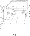
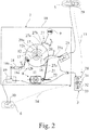
- the lock logic arrangement 1 of a motor vehicle lock arrangement 2 is in the foreground, which for the two embodiments in FIG Fig. 2 or in Fig. 4 is shown.
- the structural configuration of the motor vehicle lock assembly 2 is for the two embodiments in Fig. 1 respectively.
- the motor vehicle lock assembly 2 is mechanically coupled in the illustrated, assembled state with an outside door handle 5 and a door inner handle 6, via which here and preferably a manual and electrical or sensory detected actuation can be performed.
- the lock logic assembly 1 has a lock mechanism 7, which is equipped with an actuator 8.
- the lock mechanism 7 can be brought into mechanical, at least partially combinable lock settings by means of the actuator 8.
- the locking mechanism 3 can be manually opened depending on the mechanical lock settings by a manual operation of the outside door handle 5 and the inside door handle 6.
- the illustrated lock logic assembly 1 is particularly advantageous application in a motor vehicle lock lock assembly 2, in which a motorized opening of the locking mechanism 3 is provided in normal operation and in which an above-mentioned mechanical redundancy is provided in an emergency, for example in the event of a crash, a manual opening of the locking mechanism 3 allows.
- the mechanical redundancy is realized by the proposed lock logic assembly 1, in particular by the lock mechanism 7. Due to the special design of the lock logic arrangement 1, the structural advantages mentioned above, in particular in such an electrical motor vehicle lock arrangement 2 with mechanical redundancy, are evident.
- the lock mechanism 7 by means of the actuator 8 in a mechanical lock setting "emergency off” in which a manual operation of the outside door handle 5 is freewheeled or blocked, and in a mechanical lock setting "emergency on” in the manual operation the outside door handle 5 the locking mechanism 3 opens manually, is adjustable. That's it it is possible to activate the mechanical redundancy relating to the outside door handle 5 when an emergency occurs.
- a return mechanism 9 is preferably provided, which can be actuated by the user or by workshop personnel.
- the return mechanism 9 is key-operated, so that the provision is easily possible and at the same time there is a protection against abuse.
- a housing 10 of the lock mechanism 7 has an opening through which, possibly with a tool such as a screwdriver o. The like., A provision of the lock mechanism 7 can take place.
- the lock mechanism 7 can be "internally secured” in the mechanical lock setting, in which a manual actuation of the inside door handle 6 is freewheeled or blocked, and in the mechanical lock setting “inside unlocked”, in FIG the manual operation of the door inner handle 6, the locking mechanism 3 opens manually bring.
- the lock settings "internally secured” and “internally locked” are required if the above-mentioned lock settings “child-proof” and “theft-proof", as far as the inside door handle 6 is concerned, should be realized.
- the actuator 8 has a drive motor 11 and an actuating element 12 arranged downstream of the drive motor 11, wherein the lock mechanism 7 can be brought into at least part of the mechanical lock settings by adjusting the actuating element 12.
- the adjusting element 12 is designed here and preferably pivotable about an actuating element axis 12a. In principle, this can also be a linearly adjustable adjusting element.
- the adjusting element 12 has an actuating element pin 12b, which can be brought into engagement with other components of the lock mechanism 7 in a manner yet to be explained.
- the outside door handle 5 acts manually on the locking mechanism 3 as a function of the lock settings via a first operating line 13, while the inside door handle 6 acts manually on the blocking mechanism 3 as a function of the lock settings via a second actuating line 14.
- the actuator 8 By means of the actuator 8, the two actuating strands 13, 14 can be separated and / or blocked by also still to be explained coupling measures targeted.
- a provision of the actuating element 12 is in a second, the first direction of movement opposite direction of movement, here in the counterclockwise direction, alternately with the production of the lock setting "internally secured” and the manufacture of the lock setting "inside unlocked".
- the center position 17, as the drawing can be seen, located between the starting position 15 and the emergency position 16.
- the starting position 15, the emergency position 16 and the center position 17 each need not be a single position, but rather areas that represent the position in question may be defined.
- a switching mechanism 18 is provided, which is coupled to the actuator 12 or coupled and which, here and preferably exclusively, switches at a above-mentioned provision of the actuating element 12 between at least two mechanical switching states.
- a switching mechanism 18 is generally referred to as a ballpoint pen mechanism or as a toggle mechanism.
- a clutch 19 for switchable in the assembled state mechanical connection of the door inner handle 6 with the locking mechanism 3, by means of the actuating element 12, here and preferably via the Switching mechanism 18, is switchable.
- the clutch 19 is, as in the Fig. 2 and 4 indicated, so made that it produces a mechanical connection of the door inner handle 6 with the locking mechanism 3 or not in dependence on the switching state of the switching mechanism 18 and thus the switching state "internally protected” or “internally secured” produces.
- the switching mechanism 18 is the Fig. 2 and 4 equipped with a control lever 18a and an output lever 18b.
- the control lever 18a can be resilient in Fig. 2 deflect in the clockwise direction, whereby with each deflection of the control lever 18a of the output lever 18b in the other in Fig. 2 upper or lower position changes. This corresponds to the two above-mentioned, mechanical switching states of the switching mechanism 18.
- the clutch 19 changes into a connection to the door inner handle 6 producing or non-producing state.
- control lever 18a The shape of the control lever 18a is made such that an adjustment of the actuating element 12 out of the starting position 15 out in the first direction of movement causes no change in the switching state of the switching mechanism 18, a provision from the center position 17 out in the second direction of movement, however, a change of switching state the switching mechanism 18 and thus the change of the lock setting between "internally secured” and "innenentêtt” causes.
- the drive train between the drive motor 11 and the actuator 12 is not designed to be self-locking, so that the actuator 12 is adjustable when the drive motor 11 is switched off.
- the actuator 12 is spring-biased in the biasing direction 20a such that the actuator 12, driven by its spring bias, is adjustable.
- the actuating element 12 in the second direction of movement, in the Fig. 2 and 4 counterclockwise, biased so that the actuator 12, driven by its spring bias, is resettable.
- the spring bias of the actuating element 12 is so strong that the spring bias the actuator 12 is transferred with the drive motor 11 from the center position 17 out into the starting position 15, which an above-mentioned change between the switching setting "internally” resp. "internally secured” corresponds.
- control element 12 is associated with a coil spring 20 which generates a corresponding spring bias in the biasing direction 20a.
- the starting of the center position takes over the drive motor 11, wherein the targeted approach of the center position 17 from the starting position 15 out by means of short-circuit braking of the actuator 8, here by means of short-circuit braking of the drive motor 11 is provided.
- the control element 12 is assigned a sensor switch, in particular a microswitch, whose switching in the corresponding position of the actuating element 12 triggers the short-circuit braking.
- the sensor switch may be connected in the supply lines of the drive motor 11, so that the short-circuit current passes through the sensor switch. Alternatively or additionally, it may be provided that the short-circuit braking is triggered timed.
- a pure timing is conceivable for the motor starting of the center position 17.
- the approach of the center position 17 takes place against a blocking element, wherein the approach of the emergency position 16 is then carried out with increased drive speed and / or increased drive torque, so that the blocking element can be driven over accordingly.
- the blocking element is designed accordingly yielding.
- the above starting of the middle position 17 in the block mode is preferably combined with an above timing.
- Other possibilities for starting the center position 17 are conceivable.
- the drive motor 11 by the realization of the spring bias of the actuating element 12 only in a direction of movement, namely in the first direction of movement, the actuator 12 must act on the actuator 12. Accordingly, it is provided to reduce the design effort that the drive motor 11 drive technology unidirectionally coupled to the actuator 12, so that the driving force of the drive motor 11 to the actuator 12 just in one direction, here in the first direction of movement acts.
- a particularly robust and so far preferred embodiment provides that the drive technology coupling between the drive motor 11 and the actuating element 12, a flexible traction means 21, here and preferably a rope having.
- the flexible traction means 21 can be a band, a chain or the like.
- the illustrated embodiment of the drive train is so far particularly cost-effective and at the same time mechanically robust, since the flexible traction means 21 on a drive shaft of the actuator 8, here on the motor shaft of the drive motor 11, can be wound. As a result, a high gear ratio can be achieved without complex gear stages, in particular spur gear stages, are required.
- the first variant is the representation according to Fig. 2 refer to, in which the lock mechanism 7 has a clutch 23 for switchable in the assembled state mechanical connection of the outside door handle 5 with the locking mechanism 3, wherein the clutch 23 is switchable by means of the adjusting element 12.
- the clutch 23 is equipped with a control lever 23 a, the adjustment causes a corresponding adjustment of the coupling state of the clutch 23.
- An adjustment of the actuating element 12 from the starting position 15 out into the emergency position 16 causes an adjustment of the control lever 23 a of the clutch 23 in Fig. 2 down, whereby the mechanical connection of the outside door handle 5 is made with the locking mechanism 3.
- the outside door handle 5 is mechanically separated from the locking mechanism 3.
- the second variant for the production of lock settings "emergency on” and “emergency off” shows Fig. 4 in which a permanent mechanical connection 24 between the outside door handle 5 and the locking mechanism 3 is provided.
- an activation unit 25 which is in an activated state in which a manual operation of the outside door handle 5 to the barrier 3 (or the lock mechanism, not shown here) is passed, can be brought. Further, the activation unit 25 is brought into a deactivated state in which a manual operation of the outside door handle 5 is blocked or freewheeling. In normal operation, it is such that the activation unit 25 is in the deactivated state, so that a manual operation of the outside door handle 5 is just blocked or free running.
- the lock mechanism 7 has an activation lever 26 which is adjustable by means of the adjusting element 12 via the pin 12b and which is mechanically coupled in the mounted state with the activation unit 25 of the outside door handle 5.
- the activation unit 25 can be activated by means of the actuating element 12 as soon as the actuating element 12 reaches the emergency position 16.
- the coupling or blocking function which is required for the production of the lock setting "emergency off” or “emergency on” laid in the outside door handle 5, which further simplifies the structural design of the lock mechanism 7.
- a reset of the lock mechanism 7 effected by the actuator 8 from the mechanical lock setting "emergency on” into the mechanical lock setting “emergency off” is mechanically and / or control-technically excluded.
- a locking arrangement 27 is provided which engages in an adjustment of the actuating element 12 in the emergency position and a provision of the emergency position out, so a production of the lock setting "emergency off” locks.
- the latching arrangement 27 has a locking element 27a arranged on the adjusting element 12, which engages upon reaching the emergency position with the resilient counter-latching element 27b and leads to the production of a latching connection.
- a manual operation of the outside door handle 5 and the door inner handle 6 is not necessarily required for the sensory detectable operation.
- the grip sensors 29, 30 may be contact sensors that detect the contact of a user's hand with the respective door handle 5, 6.
- the lock logic assembly 1 in addition to the lock mechanism 7 and an electric lock control 31 for controlling the opening drive 28 on the one hand and the actuator 8 on the other. It is such that the lock control 31 in various electrical, at least partially combinable lock settings can be brought, wherein the locking mechanism 3 in the mounted state in dependence on the electrical lock settings of the lock control 31 by a sensory detected actuation of the outside door handle 5 and the inside door handle 6 can be opened by means of the opening drive 28 motor.
- the electrical lock settings of the lock control 31 are preferably stored in an electronic memory of the lock control 31.
- the locking mechanism 3 can be opened by a sensory detected actuation of the outside door handle 5 and the inside door handle 6 by means of the opening drive 28 motor.
- the lock control 31 can be “unlocked” and “locked” in the electrical lock settings and can be "child-proofed” or "anti-theft” in at least one of the electrical lock settings which are stored in a memory of the lock control 31 as mentioned above are.
- a change in the electrical lock settings is thus always accompanied by a renewed change and / overwriting of the contents of the memory of the lock control 31.
- the mechanical lock settings are consistent with the electrical lock settings such that the behavior of the motor vehicle lock assembly 2 does not differ with respect to manual actuation and electrical actuation.
- the lock control 31 at least partially tracks the mechanical lock settings by actuating the actuator 12 for the electrical lock settings.
- the lock control 31 the mechanical lock settings the electrical lock settings nachnach only insofar as the door inner handle 6 is affected by the respective lock settings.
- the door outer handle 5 remains in normal operation, as described above, in a mechanically deactivated state, so that a manual operation of the outside door handle 5 in normal operation has no effect on the barrier 3.
- the lock control 31 actuates the actuator 8 for the mechanical lock setting "emergency on" to a user input.
- a control is provided when the lock control 31 receives an emergency signal, in particular a crash signal, from a sensor 31a, here and preferably a crash sensor, and / or from a higher-level control.
- the reception of the emergency signal is particularly simple when the emergency signal is available via a CAN bus of the motor vehicle.
- the lock mechanism 7 on the one hand and the locking mechanism 3 on the other hand are designed separately from each other.
- the lock mechanism 7 has a housing 10 and the blocking mechanism 3 has a housing 32, wherein the two housings 10, 32 are preferably in turn configured separately from one another.
- the above-mentioned lock control 31 can also be accommodated in the housing 10 of the lock mechanism 7.
- lock mechanism 7 and the locking mechanism 3 are combined to form an assembly which are accommodated on a common carrier and / or in a common housing.
- the lock control 31 may also be part of this module. It may be advantageous by the simplified structural design here to use the actuator 8 twice, namely on the one hand for the production of the mechanical lock settings of the lock mechanism 7 and on the other hand for the motorized opening of the blocking mechanism. 3
- the motor vehicle lock arrangement 2 is claimed as such. On all versions that are suitable to explain the motor vehicle lock assembly 2, may be referenced.
- the locking mechanism 3 of the motor vehicle lock assembly 2 has an opening drive 28, by means of which the locking mechanism 3 can be opened.
- the blocking mechanism 3 has the closing elements latch 33 and pawl 34, wherein the opening drive 28 is drive-coupled to the pawl 34 for lifting thereof.
- the closing elements lock latch 33 and pawl 34 cooperate in a conventional manner. This is indicated accordingly in the drawings.
- an actuating arrangement with an outside door handle 5 and a door inner handle 6 as well as with a proposed motor vehicle lock arrangement 2 is claimed. Again, reference may be made to the above statements, as far as they are suitable to explain the outside door handle 5, the door inner handle 6 and the motor vehicle lock assembly 2.
- the outside door handle 5 is equipped with an activation unit 25 mentioned above. Also in this regard may be made to the above statements.
- a motor vehicle lock assembly 2 is claimed with a lock logic assembly 1 and a locking mechanism 3, wherein the motor vehicle lock assembly 2 is mechanically coupled in the assembled state with an outside door handle 5 and a door inner handle 6.
- the lock logic assembly 1 has a lock mechanism 7 with an actuator 8, wherein the lock mechanism 7 by means of the actuator 8 in mechanical, at least partially combinable with each other lock settings can be brought.
- the locking mechanism 3 can be, as explained above, manually open in the mounted state in dependence on the mechanical lock settings by a manual operation of the outside door handle 5 and the inside door handle 6.
- the blocking mechanism 3 has an opening drive 28, by means of which the blocking mechanism 3 can be opened by a motor.
Landscapes
- Lock And Its Accessories (AREA)
Applications Claiming Priority (1)
| Application Number | Priority Date | Filing Date | Title |
|---|---|---|---|
| DE202016100521.3U DE202016100521U1 (de) | 2016-02-02 | 2016-02-02 | Schlosslogikanordnung |
Publications (1)
| Publication Number | Publication Date |
|---|---|
| EP3203002A1 true EP3203002A1 (fr) | 2017-08-09 |
Family
ID=55531588
Family Applications (1)
| Application Number | Title | Priority Date | Filing Date |
|---|---|---|---|
| EP17154460.4A Pending EP3203002A1 (fr) | 2016-02-02 | 2017-02-02 | Logique d'un ensemble de serrure |
Country Status (2)
| Country | Link |
|---|---|
| EP (1) | EP3203002A1 (fr) |
| DE (1) | DE202016100521U1 (fr) |
Cited By (6)
| Publication number | Priority date | Publication date | Assignee | Title |
|---|---|---|---|---|
| WO2019137809A1 (fr) * | 2018-01-09 | 2019-07-18 | Witte Automotive Gmbh | Système de fermeture |
| WO2020001856A1 (fr) * | 2018-06-28 | 2020-01-02 | Huf Hülsbeck & Fürst Gmbh & Co. Kg | Système de fermeture et procédé d'actionnement d'un système de fermeture |
| FR3083560A1 (fr) * | 2018-07-05 | 2020-01-10 | Psa Automobiles Sa | Vehicule comprenant un dispositif d’actionnement electrique d’une serrure mecanique |
| DE102018128499A1 (de) | 2018-11-14 | 2020-05-14 | Kiekert Aktiengesellschaft | Kraftfahrzeug- Schließ- und/oder Zugangssystem |
| WO2021063440A1 (fr) * | 2019-10-02 | 2021-04-08 | Kiekert Ag | Ensemble d'entraînement pour serrure de véhicule automobile |
| WO2025131157A1 (fr) * | 2023-12-19 | 2025-06-26 | Kiekert Aktiengesellschaft | Ensemble serrure de véhicule automobile |
Families Citing this family (27)
| Publication number | Priority date | Publication date | Assignee | Title |
|---|---|---|---|---|
| DE102016113695A1 (de) * | 2016-07-25 | 2018-01-25 | Witte Automotive Gmbh | Türgriffanordnung |
| DE202016104529U1 (de) | 2016-08-18 | 2017-11-21 | BROSE SCHLIEßSYSTEME GMBH & CO. KG | Schlosslogikanordnung |
| DE102016121191A1 (de) * | 2016-11-07 | 2018-05-09 | Kiekert Ag | Schließeinrichtung für ein Kraftfahrzeug |
| WO2018082751A1 (fr) * | 2016-11-07 | 2018-05-11 | Kiekert Ag | Serrure de véhicule automobile |
| DE102016121193A1 (de) * | 2016-11-07 | 2018-05-09 | Kiekert Ag | Schließeinrichtung für ein Kraftfahrzeug |
| DE102016121184A1 (de) * | 2016-11-07 | 2018-05-09 | Kiekert Ag | Schliesseinrichtung für ein Kraftfahrzeug |
| DE102016121199A1 (de) * | 2016-11-07 | 2018-05-09 | Kiekert Ag | Schließeinrichtung für ein Kraftfahrzeug |
| DE102016121195A1 (de) * | 2016-11-07 | 2018-05-09 | Kiekert Ag | Schließeinrichtung für ein Kraftfahrzeug |
| DE102016121198A1 (de) * | 2016-11-07 | 2018-05-09 | Kiekert Ag | Schließeinrichtung für ein Kraftfahrzeug |
| KR102428684B1 (ko) * | 2016-11-07 | 2022-08-03 | 키커트 악티엔게젤샤프트 | 자동차용 로킹 장치 |
| US11066853B2 (en) * | 2018-01-04 | 2021-07-20 | Inteva Products, Llc | Electric door lock mechanism and method to override |
| DE102018101495A1 (de) | 2018-01-23 | 2019-07-25 | Brose Schließsysteme GmbH & Co. Kommanditgesellschaft | Schlosslogikanordnung |
| DE102018102874B4 (de) * | 2018-02-08 | 2021-09-02 | Witte Automotive Gmbh | System zum Steuern eines Schlosses für eine Frontklappe eines Kraftfahrzeugs |
| DE102018104421A1 (de) * | 2018-02-27 | 2019-08-29 | Kiekert Ag | Betätigungseinrichtung für ein Kraftfahrzeug-Türschloss |
| DE102018204351A1 (de) * | 2018-03-21 | 2019-09-26 | Audi Ag | Türverriegelungseinrichtung für ein Kraftfahrzeug |
| DE102018114061A1 (de) * | 2018-06-13 | 2019-12-19 | Kiekert Ag | Kraftfahrzeugtürverschluss |
| DE102018117650A1 (de) | 2018-07-20 | 2020-01-23 | BROSE SCHLIEßSYSTEME GMBH & CO. KG | Schlosslogikanordnung |
| DE102018120074A1 (de) * | 2018-08-17 | 2020-02-20 | Witte Automotive Gmbh | Schließsystem |
| CN109025556B (zh) * | 2018-08-21 | 2020-04-03 | 天津经纬恒润科技有限公司 | 一种汽车门锁闭环控制方法及装置 |
| DE102018128854A1 (de) * | 2018-11-16 | 2020-05-20 | Huf Hülsbeck & Fürst Gmbh & Co. Kg | Kraftfahrzeug-Schließsystem |
| DE102019100743A1 (de) * | 2019-01-14 | 2020-07-16 | Bayerische Motoren Werke Aktiengesellschaft | Staufachverriegelungs-Baukastensystem und Kraftfahrzeug mit Verriegelungssystem |
| DE102019002873B4 (de) | 2019-04-17 | 2025-06-12 | Mercedes-Benz Group AG | Schließeinrichtung für eine Fahrzeugtür eines Kraftfahrzeug |
| DE102020111053A1 (de) * | 2020-04-23 | 2021-10-28 | Kiekert Aktiengesellschaft | Kraftfahrzeugschloss |
| DE102021102592A1 (de) * | 2021-02-04 | 2022-08-04 | Kiekert Aktiengesellschaft | Kraftfahrzeugschloss |
| DE102021112957A1 (de) | 2021-05-19 | 2022-11-24 | Kiekert Aktiengesellschaft | Kraftfahrzeug-Schloss insbesondere Kraftfahrzeug-Türschloss |
| DE102022122785A1 (de) * | 2021-09-16 | 2023-03-16 | Magna Closures Inc. | Verschlussverriegelung mit unfall-entriegelungsmechanismus mit einem einzigen elektromotor |
| DE102022120976A1 (de) * | 2022-08-19 | 2024-02-22 | Kiekert Aktiengesellschaft | Kombination aus einem Kraftfahrzeugschloss und einer Kraftfahrzeug-Schloss-Funktionseinheit |
Citations (14)
| Publication number | Priority date | Publication date | Assignee | Title |
|---|---|---|---|---|
| DE19635741A1 (de) * | 1995-09-04 | 1997-03-06 | Aisin Seiki | Entriegelungsvorrichtung für ein Türschloß eines Fahrzeugs |
| DE19547727A1 (de) * | 1995-12-20 | 1997-06-26 | Vdo Schindling | Einrichtung zum Entriegeln von Türen |
| DE19631869A1 (de) | 1996-08-07 | 1998-02-12 | Bosch Gmbh Robert | Kraftfahrzeug-Türschloß oder dergleichen |
| WO1999041474A1 (fr) * | 1998-02-11 | 1999-08-19 | Rover Group Limited | Systeme de fermeture d'une porte de vehicule a moteur |
| DE19928230A1 (de) * | 1999-05-28 | 2000-12-07 | Bosch Gmbh Robert | Kraftfahrzeug-Türschloß o. dgl. |
| DE10011563A1 (de) * | 2000-03-09 | 2001-10-11 | Bosch Gmbh Robert | Kraftfahrzeugschloß |
| DE10018194A1 (de) * | 2000-04-12 | 2001-10-25 | Bayerische Motoren Werke Ag | Sicherungseinrichtung an einer Fahrzeugtür |
| EP1457625A2 (fr) * | 2003-03-08 | 2004-09-15 | Brose Schliesssysteme GmbH & Co. KG | Serrure pour véhicule à ouverture assistée électriquement |
| DE102004030160A1 (de) * | 2004-06-22 | 2006-01-19 | Brose Schließsysteme GmbH & Co.KG | Kraftfahrzeugschloß mit motorischem Öffnungsantrieb |
| US20080224482A1 (en) * | 2007-02-15 | 2008-09-18 | Cumbo Francesco | Electrical Door Latch |
| DE202008003845U1 (de) * | 2008-03-19 | 2009-08-13 | Kiekert Ag | Türverschlusseinheit für ein Kraftfahrzeug |
| DE102011113647A1 (de) * | 2011-09-19 | 2013-03-21 | Audi Ag | Kraftfahrzeugschloss |
| DE102012003743A1 (de) * | 2012-02-28 | 2013-08-29 | Kiekert Aktiengesellschaft | Kraftfahrzeugtürverschluss |
| DE102013110201A1 (de) * | 2013-09-16 | 2015-03-19 | BROSE SCHLIEßSYSTEME GMBH & CO. KG | Kraftfahrzeugschloss |
-
2016
- 2016-02-02 DE DE202016100521.3U patent/DE202016100521U1/de not_active Expired - Lifetime
-
2017
- 2017-02-02 EP EP17154460.4A patent/EP3203002A1/fr active Pending
Patent Citations (14)
| Publication number | Priority date | Publication date | Assignee | Title |
|---|---|---|---|---|
| DE19635741A1 (de) * | 1995-09-04 | 1997-03-06 | Aisin Seiki | Entriegelungsvorrichtung für ein Türschloß eines Fahrzeugs |
| DE19547727A1 (de) * | 1995-12-20 | 1997-06-26 | Vdo Schindling | Einrichtung zum Entriegeln von Türen |
| DE19631869A1 (de) | 1996-08-07 | 1998-02-12 | Bosch Gmbh Robert | Kraftfahrzeug-Türschloß oder dergleichen |
| WO1999041474A1 (fr) * | 1998-02-11 | 1999-08-19 | Rover Group Limited | Systeme de fermeture d'une porte de vehicule a moteur |
| DE19928230A1 (de) * | 1999-05-28 | 2000-12-07 | Bosch Gmbh Robert | Kraftfahrzeug-Türschloß o. dgl. |
| DE10011563A1 (de) * | 2000-03-09 | 2001-10-11 | Bosch Gmbh Robert | Kraftfahrzeugschloß |
| DE10018194A1 (de) * | 2000-04-12 | 2001-10-25 | Bayerische Motoren Werke Ag | Sicherungseinrichtung an einer Fahrzeugtür |
| EP1457625A2 (fr) * | 2003-03-08 | 2004-09-15 | Brose Schliesssysteme GmbH & Co. KG | Serrure pour véhicule à ouverture assistée électriquement |
| DE102004030160A1 (de) * | 2004-06-22 | 2006-01-19 | Brose Schließsysteme GmbH & Co.KG | Kraftfahrzeugschloß mit motorischem Öffnungsantrieb |
| US20080224482A1 (en) * | 2007-02-15 | 2008-09-18 | Cumbo Francesco | Electrical Door Latch |
| DE202008003845U1 (de) * | 2008-03-19 | 2009-08-13 | Kiekert Ag | Türverschlusseinheit für ein Kraftfahrzeug |
| DE102011113647A1 (de) * | 2011-09-19 | 2013-03-21 | Audi Ag | Kraftfahrzeugschloss |
| DE102012003743A1 (de) * | 2012-02-28 | 2013-08-29 | Kiekert Aktiengesellschaft | Kraftfahrzeugtürverschluss |
| DE102013110201A1 (de) * | 2013-09-16 | 2015-03-19 | BROSE SCHLIEßSYSTEME GMBH & CO. KG | Kraftfahrzeugschloss |
Cited By (10)
| Publication number | Priority date | Publication date | Assignee | Title |
|---|---|---|---|---|
| WO2019137809A1 (fr) * | 2018-01-09 | 2019-07-18 | Witte Automotive Gmbh | Système de fermeture |
| US20210062556A1 (en) * | 2018-01-09 | 2021-03-04 | Witte Automotive Gmbh | Closing system |
| US11753855B2 (en) * | 2018-01-09 | 2023-09-12 | Witte Automotive Gmbh | Closing system |
| WO2020001856A1 (fr) * | 2018-06-28 | 2020-01-02 | Huf Hülsbeck & Fürst Gmbh & Co. Kg | Système de fermeture et procédé d'actionnement d'un système de fermeture |
| FR3083560A1 (fr) * | 2018-07-05 | 2020-01-10 | Psa Automobiles Sa | Vehicule comprenant un dispositif d’actionnement electrique d’une serrure mecanique |
| DE102018128499A1 (de) | 2018-11-14 | 2020-05-14 | Kiekert Aktiengesellschaft | Kraftfahrzeug- Schließ- und/oder Zugangssystem |
| WO2020098865A1 (fr) | 2018-11-14 | 2020-05-22 | Kiekert Ag | Système de fermeture et/ou d'accès d'un véhicule automobile |
| WO2021063440A1 (fr) * | 2019-10-02 | 2021-04-08 | Kiekert Ag | Ensemble d'entraînement pour serrure de véhicule automobile |
| WO2025131157A1 (fr) * | 2023-12-19 | 2025-06-26 | Kiekert Aktiengesellschaft | Ensemble serrure de véhicule automobile |
| DE102023135702A1 (de) * | 2023-12-19 | 2025-06-26 | Kiekert Aktiengesellschaft | Kraftfahrzeugschlossanordnung |
Also Published As
| Publication number | Publication date |
|---|---|
| DE202016100521U1 (de) | 2016-02-29 |
Similar Documents
| Publication | Publication Date | Title |
|---|---|---|
| EP3203002A1 (fr) | Logique d'un ensemble de serrure | |
| EP1304433B1 (fr) | Serrure de la porte d'automobile avec une unité de fermeture et une unité de commande separarée l'un de l'autre | |
| DE19530726C5 (de) | Zentralverriegelungsanlage mit baugleichen Kraftfahrzeugtürverschlüssen | |
| EP1317596B1 (fr) | Serrure de porte d'automobile a mode combine de condamnation et d'ouverture centralisees | |
| DE19635414C2 (de) | Schloß, insbesondere für Fahrzeugtüren oder dergleichen | |
| EP2193247B1 (fr) | Serrure de véhicule automobile | |
| EP2820207B1 (fr) | Fermeture de portière de véhicule à moteur | |
| EP3303741B1 (fr) | Serrure de porte de véhicule | |
| DE202012003171U1 (de) | Kraftfahrzeugtürverschluss | |
| DE202011005608U1 (de) | Kraftfahrzeugschloss | |
| DE2911681A1 (de) | Zentralgesteuerte verschlusseinrichtung fuer kraftfahrzeugtueren | |
| DE102017101417A1 (de) | Türgriffanordnung für eine Fahrzeugtür | |
| EP1556570B1 (fr) | Procede d'actionnement d'un cliquet d'arret au sein d'une serrure pourvue d'une clenche pivotante pour un vehicule automobile | |
| EP3284885A1 (fr) | Système de serrure de véhicule automobile | |
| WO2016192708A1 (fr) | Procédé de commande d'une serrure de porte de véhicule à moteur | |
| EP1457625A2 (fr) | Serrure pour véhicule à ouverture assistée électriquement | |
| DE10258645B4 (de) | Kraftfahrzeug-Türschloß | |
| EP1408187B1 (fr) | Dispositif d'actionnement d'une serrure pour portes, volets, ou similaires, en particulier sur véhicules | |
| EP1283934A1 (fr) | Systeme de fermeture de portes automobile avec deverrouillage rapide | |
| DE19742798B4 (de) | Kraftfahrzeug-Türschloß o. dgl. mit Öffnungshilfe und Kindersicherung | |
| DE4005641C2 (fr) | ||
| DE19547728C2 (de) | Schaltungsanordnung mit einer elektrischen Stelleinrichtung | |
| DE19924458B4 (de) | Kraftfahrzeug-Türschließeinrichtung | |
| DE19756266A1 (de) | Schließeinrichtung | |
| DE10319743B4 (de) | Kraftfahrzeugschloß mit elektrischem Öffnungsantrieb |
Legal Events
| Date | Code | Title | Description |
|---|---|---|---|
| PUAI | Public reference made under article 153(3) epc to a published international application that has entered the european phase |
Free format text: ORIGINAL CODE: 0009012 |
|
| STAA | Information on the status of an ep patent application or granted ep patent |
Free format text: STATUS: THE APPLICATION HAS BEEN PUBLISHED |
|
| AK | Designated contracting states |
Kind code of ref document: A1 Designated state(s): AL AT BE BG CH CY CZ DE DK EE ES FI FR GB GR HR HU IE IS IT LI LT LU LV MC MK MT NL NO PL PT RO RS SE SI SK SM TR |
|
| AX | Request for extension of the european patent |
Extension state: BA ME |
|
| STAA | Information on the status of an ep patent application or granted ep patent |
Free format text: STATUS: REQUEST FOR EXAMINATION WAS MADE |
|
| 17P | Request for examination filed |
Effective date: 20180209 |
|
| RBV | Designated contracting states (corrected) |
Designated state(s): AL AT BE BG CH CY CZ DE DK EE ES FI FR GB GR HR HU IE IS IT LI LT LU LV MC MK MT NL NO PL PT RO RS SE SI SK SM TR |
|
| STAA | Information on the status of an ep patent application or granted ep patent |
Free format text: STATUS: EXAMINATION IS IN PROGRESS |
|
| 17Q | First examination report despatched |
Effective date: 20191009 |