EP3203040A1 - Hebevorrichtung für ein turbinegehäuse und verfahren zum heben des gehäuses - Google Patents
Hebevorrichtung für ein turbinegehäuse und verfahren zum heben des gehäuses Download PDFInfo
- Publication number
- EP3203040A1 EP3203040A1 EP17154879.5A EP17154879A EP3203040A1 EP 3203040 A1 EP3203040 A1 EP 3203040A1 EP 17154879 A EP17154879 A EP 17154879A EP 3203040 A1 EP3203040 A1 EP 3203040A1
- Authority
- EP
- European Patent Office
- Prior art keywords
- casing
- assembly
- frame
- sections
- casing sections
- Prior art date
- Legal status (The legal status is an assumption and is not a legal conclusion. Google has not performed a legal analysis and makes no representation as to the accuracy of the status listed.)
- Granted
Links
Images


Classifications
-
- F—MECHANICAL ENGINEERING; LIGHTING; HEATING; WEAPONS; BLASTING
- F01—MACHINES OR ENGINES IN GENERAL; ENGINE PLANTS IN GENERAL; STEAM ENGINES
- F01D—NON-POSITIVE DISPLACEMENT MACHINES OR ENGINES, e.g. STEAM TURBINES
- F01D25/00—Component parts, details, or accessories, not provided for in, or of interest apart from, other groups
- F01D25/28—Supporting or mounting arrangements, e.g. for turbine casing
- F01D25/285—Temporary support structures, e.g. for testing, assembling, installing, repairing; Assembly methods using such structures
-
- F—MECHANICAL ENGINEERING; LIGHTING; HEATING; WEAPONS; BLASTING
- F01—MACHINES OR ENGINES IN GENERAL; ENGINE PLANTS IN GENERAL; STEAM ENGINES
- F01D—NON-POSITIVE DISPLACEMENT MACHINES OR ENGINES, e.g. STEAM TURBINES
- F01D25/00—Component parts, details, or accessories, not provided for in, or of interest apart from, other groups
- F01D25/24—Casings; Casing parts, e.g. diaphragms, casing fastenings
-
- F—MECHANICAL ENGINEERING; LIGHTING; HEATING; WEAPONS; BLASTING
- F02—COMBUSTION ENGINES; HOT-GAS OR COMBUSTION-PRODUCT ENGINE PLANTS
- F02C—GAS-TURBINE PLANTS; AIR INTAKES FOR JET-PROPULSION PLANTS; CONTROLLING FUEL SUPPLY IN AIR-BREATHING JET-PROPULSION PLANTS
- F02C7/00—Features, components parts, details or accessories, not provided for in, or of interest apart form groups F02C1/00 - F02C6/00; Air intakes for jet-propulsion plants
- F02C7/20—Mounting or supporting of plant; Accommodating heat expansion or creep
-
- F—MECHANICAL ENGINEERING; LIGHTING; HEATING; WEAPONS; BLASTING
- F05—INDEXING SCHEMES RELATING TO ENGINES OR PUMPS IN VARIOUS SUBCLASSES OF CLASSES F01-F04
- F05D—INDEXING SCHEME FOR ASPECTS RELATING TO NON-POSITIVE-DISPLACEMENT MACHINES OR ENGINES, GAS-TURBINES OR JET-PROPULSION PLANTS
- F05D2220/00—Application
- F05D2220/30—Application in turbines
- F05D2220/32—Application in turbines in gas turbines
-
- F—MECHANICAL ENGINEERING; LIGHTING; HEATING; WEAPONS; BLASTING
- F05—INDEXING SCHEMES RELATING TO ENGINES OR PUMPS IN VARIOUS SUBCLASSES OF CLASSES F01-F04
- F05D—INDEXING SCHEME FOR ASPECTS RELATING TO NON-POSITIVE-DISPLACEMENT MACHINES OR ENGINES, GAS-TURBINES OR JET-PROPULSION PLANTS
- F05D2230/00—Manufacture
- F05D2230/60—Assembly methods
- F05D2230/68—Assembly methods using auxiliary equipment for lifting or holding
-
- F—MECHANICAL ENGINEERING; LIGHTING; HEATING; WEAPONS; BLASTING
- F05—INDEXING SCHEMES RELATING TO ENGINES OR PUMPS IN VARIOUS SUBCLASSES OF CLASSES F01-F04
- F05D—INDEXING SCHEME FOR ASPECTS RELATING TO NON-POSITIVE-DISPLACEMENT MACHINES OR ENGINES, GAS-TURBINES OR JET-PROPULSION PLANTS
- F05D2240/00—Components
- F05D2240/10—Stators
- F05D2240/14—Casings or housings protecting or supporting assemblies within
Definitions
- the invention relates to lifting and moving industrial gas turbines.
- the invention particularly relates to lifting and moving the casing for power generation sites lacking the capacity to lift or move the entire gas turbine.
- a method has been invented that enables lifting and moving of a partially assembled gas turbine casing, without requiring the realignment of the casings after the lift.
- the mass of the casing assembly is reduced by removing a section of the casing before the remaining partially assembled casing is lifted and moved.
- a novel frame is fastened to the casing for the gas turbine to provide support for missing sections of the casing.
- the frame is bolted to both horizontal and vertical joints of sections of the partially casing assembly.
- the frame provides substantially the same structural support to the casing as would have been provided by the removed casing section.
- the partially assembled gas turbine casing with the frame is lifted and transported with minimal risk that the casing sections will deform and require alignment after the lift and transport.
- the invention is a partially assembled casing for a turbine including: an assembly of connected casing sections, wherein the assembly does not form a complete casing for the turbine; a gap in the assembly of connected casing sections, wherein the gap corresponds to an absent casing section which is not included in the assembly of connected casing sections, and a frame inserted in the gap and providing structural support to the assembly of connected casing sections.
- the invention may also be embodied as A partially assembled casing for a gas turbine including: an assembly of connected casing sections, wherein the assembly does not form a complete casing for the turbine and the casing sections include upper and lower casing sections for a turbine, upper and lower casing sections for a compressor and a lower casing section for an inlet; a gap in the assembly of connected casing sections, wherein the gap corresponds to an absent upper casing section for the inlet, and a frame inserted in the gap and providing structural support to the assembly of connected casing sections, wherein the frame includes a first bracket fastened to an exposed joint surface of the upper casing section for the compressor and a second bracket fastened to an exposed joint surface of the lower casing section for the inlet.
- the invention is a method to move a turbine casing including: assembling casing sections to form a partial assembly of casing sections, wherein a gap remains in the assembly of casing sections at a location corresponding to an absent casing section; attaching a frame to the assembly of casing sections, wherein the frame is in the gap and the frame is attached to a vertical joint surface and a horizontal joint surface on the assembly; attaching a lifting device to the assembly of casing sections with the attached frame, and lifting the assembly of casing sections with the attached frame, with the lifting device.
- An industrial gas turbine may have a mass of, for example, in a range of 100 to 300 tons (90,000 kg to 272,000 kg).
- the dimensions of an industrial gas turbine may be, for example, a length of 30 to 50 feet (9 to 15 meters), and height and width of 12 to 20 feet (3.5 to 6m).
- Lifting a partially assembled gas turbine and, particularly, where one or more sections of the casing are removed before the lift creates a larger potential risk that the gas turbine will deform during the lift and the casing will require alignment after the lift.
- the casing may deform due to the shift in the forces applied to the casing during the lift. The deformation increases the risk of misalignment between the casing and the casing section that is attached after the lift.
- Figure 1 illustrates an industrial gas turbine 10 seated on a shipping support frame 12 and attached to a crane 14 by lifting cables 16.
- the lifting cables attach to lifting posts 18 on opposite sides of the casing.
- the lifting posts 18 are generally at a mid-height of the casing and positioned near a horizontal joint 20 between the upper and lower sections of the casing of the gas turbine.
- the inventors recognized a need for a better method to move a partially disassembled industrial gas turbine.
- the inventors conceived of a method and a frame which reduce the time and associated cost in lifting and moving a gas turbine casing and reduces the risk of deforming the casing sections during a lift of move.
- sections of the upper casing are temporarily removed to allow removal of the rotor, and most of the sections of the upper casing are attached to the lower casing after the rotor is removed.
- a frame is attached to the lower casing and the remaining upper casing. The frame prevents deformation of the casing while the partially assembled gas turbine casing is lifted and moved.
- the casing By partially reassembling the casing after removal of the rotor, the casing becomes more structurally rigid due to the completed joints between the sections of the casing.
- the frame provides the casing support functions that would have been performed by the removed casing section. Because the casing sections supported by being joined to other casing sections or to the frame, all of the casing sections are less subject to deformation while be lifted and removed.
- the mass, e.g., weight, of the partially assembled casings is substantially less than the mass of the gas turbine with rotor. Also the removal of one or more casing sections reduces the mass of the casings. The lower mass allows the partially assembled casings to be removed from smaller cranes and for the casings to be moved with transports, such as trucks, that are able to travel over roads that cannot support the entire weight of a complete gas turbine.
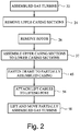
- Figure 2 is a flow chart of an exemplary method to partially disassemble and move an industrial gas turbine.
- the gas turbine is in a fully assembled condition with the rotor in place in step 22.
- the fully assembled gas turbine may be on a support frame for transport or maintenance, such as shown in Figure 1 .
- the gas turbine may be on an operational support frame on site at a power generation facility.
- the inlet end of the gas turbine may be coupled to an air outlet of an air duct assembly, and the turbine exhaust end of the gas turbine may be connected to the inlet of an exhaust diffuser.
- the available working space around gas turbine may be small and insufficient to allow rebuilding and extensive maintenance of the gas turbine.
- the gas turbine often must be moved to a maintenance facility or a site at the power generation facility that has sufficient working space around the gas turbine for rebuilding and maintenance.
- step 24 the upper casing of the gas turbine is removed to expose the rotor.
- step 26 a crane above the gas turbine lifts the rotor from the lower casing of the gas turbine. The rotor may be moved separately from the casing to a site where it may be repaired, maintained or otherwise rebuilt.
- Figure 3 shows a gas turbine 10 in which the upper casing has been removed and the rotor 28 is exposed.
- the rotor which includes a shaft, rows of blades for an axial compressor and rows of buckets (blades) of an axial turbine.
- the rotor may be lifted upward to be removed from the lower casing 30 of the gas turbine.
- the lower casing 30 and the upper casing are each an assembly of casing sections.
- the casing sections may each extend halfway around the rotor, such that the casing sections are either upper or lower sections.
- An upper and lower casing section when assembled extends entirely around the rotor.
- the casing sections may be quarter sections that each extend around one quarter of the perimeter of the rotor.
- the casing assembly is segmented into casing sections.
- the casing assembly includes lower and upper sections for an inlet casing 32 (see Figs. 1 and 2 ), a compressor casing 34, a combustor casing 36, a turbine casing 38, and a turbine exhaust casing 39.
- the upper and lower compressor sections 34 house the portion of the rotor including axial compressor blades and of stationary vanes between the rows of compressor blades.
- the upper and lower casing sections for the compressor and combustor may each be each a single piece component.
- the upper and lower combustor casing sections include openings and supports for combustion cans arranged in an annular array around the perimeter of the casing.
- the upper and lower turbine casing sections house the turbine section of the rotor which includes rows of stationary nozzles between the rows of the turbine buckets.
- Figure 3 shows that the lower casing sections assembled together and exposing horizontal surfaces 40 on opposite sides of the rotor and extending the length of the gas turbine.
- the joint surfaces 40 include bolt holes to receive the bolts or other fasteners for the casings.
- each casing section has joint surfaces, typically vertical or horizontal planar surfaces.
- the joint surfaces are configured to abut and align with joint surfaces of adjacent casing sections horizontal or vertical joint lines.
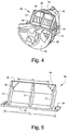
- Figure 4 shows a front portion of a partially reassembled gas turbine casing 42.
- the rotor has been removed from the casing 42 while the lower half casing sections remained assembled.
- the upper casing sections have been reattached to the casing by bolting each upper casing section to its corresponding lower casing sections and to adjacent upper casing sections.
- the partially assembled casing 42 includes all sections of the lower half of the casing and all of the sections of the upper half except for the inlet casing.
- a frame 44 is fastened to the partially assembled casing in step 45.
- the frame provides the structural support to the casing that would have otherwise been provided by the upper inlet casing.
- the casing sections are all either bolted to each other or to the frame.
- the partial casing assembly 42 is kept in alignment because the casing sections and frame are bolted together.
- the bolts joining adjacent sections ofthe casing maintain the alignment of the bolt holes in the adjacent sections.
- the bolts extending through the frame and the casing sections adjacent to the frame maintain the alignment between the bolt holes in those casings and the bolt holes in the frame.
- the frame 44 has sufficient structural rigidity to prevent deformation of the casing sections to which the frame is attached.
- the bolt holes 46 in the frame are aligned with corresponding bolt holes in an adjacent section of the casing.
- the frame 44 includes a first bracket 48 having a vertically oriented surface and bolt holes 46 corresponding to the bolt holes in a casing section to which the first bracket is configured to be attached.
- the first bracket may be a metal plate having a thickness of several inches or more, e.g., three inches or 25mm.
- the first bracket has two sets of bolt holes 46. Each set of bolt holes may be two, three, four or more bolt holes. Each set of bolt holes may be configured to align with a set of consecutive bolt holes on a joint surface of one of the casing sections.
- the two sets of bolt holes on the first bracket align with sets of bolt holes on a vertical joint surface of the upper compressor casing section.
- the two sets of bolt holes are on opposite sides of the upper compressor casing.
- the frame also includes a second bracket 50 having a horizontal oriented surface with holes corresponding to the bolt holes in a casing section to which the second bracket is configured to attach.
- the second bracket may be a metal plate having the same thickness as the first bracket.
- the horizontally oriented surface may be a horizontal planar surface.
- the second bracket may be longer than the first bracket.
- the second bracket spans the width of the casing along a center plane of the casing, which is the widest portion of the casing.
- the first bracket spans an upper (or lower) region of the casing that is offset from the center plane.
- the gap G1 between the two sets of bolt holes on the upper casing section aligned with the sets of bolt holes on the first bracket determines the length of the first bracket.
- the gap G2 between the two sets of bolt holes on opposite sides of the lower inlet casing section determines the length of the second bracket.
- the second bracket 50 may be positioned on the casing assembly to be adjacent a lifting attachment device 51.
- the lifting attachment device may be lifting posts, apertures to receive a hook of a crane or other device that provides a grip to receive the lifting cables of a crane.
- the lifting attachment device may be on opposite sides of the casing, such as on opposite sides of the lower inlet casing 54.
- step 56 ( Fig. 2 ) lifting cables are attached to the lifting attachment devices on opposite sides of the partially assembled casing.
- a crane attached to the lifting cables lifts and moves the partially assembled casing with the attached frame. The lifting and movement of the partially assembled casing is accomplished without unduly deforming the casing or creating a need for a time-consuming and expensive realignment of the casing sections.
- the first and second brackets are joined by ribs 52 extending between the brackets.
- the ribs may be metal plates welded at each end to one of the brackets.
- the ends of each rib may be configured to contact one of the brackets along the entire length of the end.
- the welds between the rib end and the bracket may extend the length of the rib end and be on opposite sides of the rib ends.
- There may be three ribs wherein two of the ribs are near the bolt holes in the brackets and the third rib is at a center region of the frame.
- the thickness of the ribs may be substantially, e.g., within fifteen percent, of the thickness of either of the brackets.
- the ribs may be each in a plane parallel to the axis of the casing. By orienting the ribs in a plane parallel to the casing axis, the forces applied in an axial direction against the upper or lower brackets are transmitted along the centerline of the ribs with minimal torsion being applied to the ribs.
- the upper ends of the outer two ribs may be welded to ends of the first bracket.
- the lower ends of the outer two ribs may be welded to an upper planar surface of the second bracket and be welded inward of the sets of the bolt holes on the second bracket.
- the mass ofthe frame is substantially, e.g., less than one third, ofthe mass of the section of the casing being replaced by the frame.
- the inlet casing sections typically have a large mass relative to the other casing sections. Removing the upper inlet casing section reduces substantially, e.g., by over twenty percent, the mass of the casing of the gas turbine.
- the frame may be less than one third the mass of the upper inlet casing section.
- By replacing the upper inlet casing section with the frame the mass of the remaining gas turbine casing assembly may be reduced by ten to fifteen percent.
- the reduction in mass may be sufficient to allow the partially assembled gas turbine casing to be lifted by a crane from a particular power generation site.
- the reduction in mass may be sufficient to allow the partially assembled gas turbine casing to be transported over the roads leading from the power generation site.
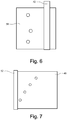
- Figures 6 and 7 show plan views of the first and second brackets. These views show the pattern of the bolt holes in brackets 48, 50.
- the number and pattern of bolt holes are machined, e.g., drilled, and with sufficient precision to accurately alight with the bolt holes on the casing sections to which the brackets attach.
- Each group of bolt holes may be arranged in an arc as shown in Figures 6 and 7 , or in a straight or curvilinear line. The arrangement of bolts holes will depend on the shape of the surface of the casing to which the bracket is to be fastened.
- the bolt holes in the brackets are selected and positioned such that when bolts are inserted through the bolt holes and into the section casings, the bolts are sufficiently supported by the brackets to ensure that the section casing maintain proper alignment. Proper alignment is needed so that the missing casing section can be attached to the partial assembly of casing sections, preferably without extensive realignment of the missing casing section with the assembly of casing sections.
- the ribs 52 may be attached to the first and second bracket proximate to, e.g., within five inches of, one of the bolt holes. By minimizing the distance between the rib and the nearest bolt hole to the rib, the moment forces are reduced that are applied to the bracket by the bolts and the rib.
- the number of support ribs, thickness of the brackets and ribs, and number and location of the bolt holes are dependent on the mass and size of the gas turbine.
- a finite element analysis may be performed to model the partially assembled casing and frame.
- the FEA model may be used to determine whether the partially assembled casing with the frame may be lifted and moved without unduly deforming the casing or creating a need for an extensive realignment of the casing sections.
Landscapes
- Engineering & Computer Science (AREA)
- Mechanical Engineering (AREA)
- General Engineering & Computer Science (AREA)
- Chemical & Material Sciences (AREA)
- Combustion & Propulsion (AREA)
- Structures Of Non-Positive Displacement Pumps (AREA)
- Turbine Rotor Nozzle Sealing (AREA)
Applications Claiming Priority (1)
| Application Number | Priority Date | Filing Date | Title |
|---|---|---|---|
| US15/017,968 US10184357B2 (en) | 2016-02-08 | 2016-02-08 | Lift device for turbine casing and method to lift the casing |
Publications (2)
| Publication Number | Publication Date |
|---|---|
| EP3203040A1 true EP3203040A1 (de) | 2017-08-09 |
| EP3203040B1 EP3203040B1 (de) | 2020-04-01 |
Family
ID=57995049
Family Applications (1)
| Application Number | Title | Priority Date | Filing Date |
|---|---|---|---|
| EP17154879.5A Active EP3203040B1 (de) | 2016-02-08 | 2017-02-06 | Hebevorrichtung für ein turbinegehäuse und verfahren zum heben des gehäuses |
Country Status (4)
| Country | Link |
|---|---|
| US (1) | US10184357B2 (de) |
| EP (1) | EP3203040B1 (de) |
| JP (1) | JP6929077B2 (de) |
| CN (1) | CN107044305B (de) |
Families Citing this family (3)
| Publication number | Priority date | Publication date | Assignee | Title |
|---|---|---|---|---|
| JP7390963B2 (ja) * | 2020-04-20 | 2023-12-04 | 三菱重工コンプレッサ株式会社 | 吊り具、支持治具、回転機械の分解方法、及び回転機械の組立方法 |
| US11614002B2 (en) * | 2020-10-30 | 2023-03-28 | Raytheon Technologies Corporation | Split case structure for a gas turbine engine |
| CN113431703B (zh) * | 2021-06-30 | 2022-07-12 | 中国航发动力股份有限公司 | 一种多层装配结构的复合装配方法 |
Citations (3)
| Publication number | Priority date | Publication date | Assignee | Title |
|---|---|---|---|---|
| US8127417B1 (en) * | 2007-02-26 | 2012-03-06 | American Airlines, Inc. | Bearing assembly removal system and method |
| US8876448B1 (en) * | 2013-08-28 | 2014-11-04 | General Electric Company | Gas turbine half-casing shipping fixture |
| EP2851522A1 (de) * | 2013-09-19 | 2015-03-25 | Siemens Aktiengesellschaft | Drehvorrichtung für eine Gasturbine und Verfahren zum Drehen eines Bauteils |
Family Cites Families (7)
| Publication number | Priority date | Publication date | Assignee | Title |
|---|---|---|---|---|
| FR2646469B1 (fr) | 1989-04-28 | 1991-07-05 | Alsthom Gec | Systeme de supportage du rotor dans une turbine a echappement axial avec le palier cote echappement integre a la fondation |
| US6352404B1 (en) | 2000-02-18 | 2002-03-05 | General Electric Company | Thermal control passages for horizontal split-line flanges of gas turbine engine casings |
| DE102006027237A1 (de) * | 2005-06-14 | 2006-12-28 | Alstom Technology Ltd. | Dampfturbine |
| GB0613929D0 (en) * | 2006-07-13 | 2006-08-23 | Rolls Royce Plc | An engine core stand arrangement and method of removal and transportation of an engine core |
| US9038253B2 (en) * | 2011-04-29 | 2015-05-26 | General Electric Company | System and method for lifting a casing section |
| US9273569B2 (en) | 2013-01-08 | 2016-03-01 | General Electric Company | Gas turbine half-casing lifting and shipping fixture |
| US20140356152A1 (en) * | 2013-06-04 | 2014-12-04 | General Electric Company | Apparatus for moving turbine shell |
-
2016
- 2016-02-08 US US15/017,968 patent/US10184357B2/en active Active
-
2017
- 2017-02-06 EP EP17154879.5A patent/EP3203040B1/de active Active
- 2017-02-07 JP JP2017020032A patent/JP6929077B2/ja active Active
- 2017-02-08 CN CN201710069304.7A patent/CN107044305B/zh active Active
Patent Citations (3)
| Publication number | Priority date | Publication date | Assignee | Title |
|---|---|---|---|---|
| US8127417B1 (en) * | 2007-02-26 | 2012-03-06 | American Airlines, Inc. | Bearing assembly removal system and method |
| US8876448B1 (en) * | 2013-08-28 | 2014-11-04 | General Electric Company | Gas turbine half-casing shipping fixture |
| EP2851522A1 (de) * | 2013-09-19 | 2015-03-25 | Siemens Aktiengesellschaft | Drehvorrichtung für eine Gasturbine und Verfahren zum Drehen eines Bauteils |
Also Published As
| Publication number | Publication date |
|---|---|
| US10184357B2 (en) | 2019-01-22 |
| JP6929077B2 (ja) | 2021-09-01 |
| US20170226898A1 (en) | 2017-08-10 |
| EP3203040B1 (de) | 2020-04-01 |
| CN107044305A (zh) | 2017-08-15 |
| CN107044305B (zh) | 2021-10-15 |
| JP2017141831A (ja) | 2017-08-17 |
Similar Documents
| Publication | Publication Date | Title |
|---|---|---|
| CN104417957B (zh) | 运输固定装置以及涡轮下半壳体和运输固定装置组合件 | |
| US8672606B2 (en) | Gas turbine engine and system for servicing a gas turbine engine | |
| US9863279B2 (en) | Multipurpose support system for a gas turbine | |
| US8752337B2 (en) | Tower part for a wind turbine, an aperture cover system, a method for manufacturing a tower part and uses hereof | |
| US9539680B2 (en) | Auxiliary member for assembly/disassembly of gas turbine casing, gas turbine having the same, assembly method of gas turbine casing, and disassembly method of gas turbine casing | |
| US20100218508A1 (en) | System for supporting and servicing a gas turbine engine | |
| US20120073215A1 (en) | Enclosure for power generation system | |
| EP3203040B1 (de) | Hebevorrichtung für ein turbinegehäuse und verfahren zum heben des gehäuses | |
| CN102765654A (zh) | 用于提升壳体区段的系统和方法 | |
| JP7053166B2 (ja) | タービンの出荷/運転のための支持組立体 | |
| US20120171031A1 (en) | Removable upper steam guide segment for steam turbine | |
| CN105189939B (zh) | 用于排气涡轮增压器的组装工具 | |
| US20180119576A1 (en) | Exhaust collector railing removal tool | |
| US8662821B2 (en) | Removable steam inlet assembly for steam turbine | |
| US9780628B2 (en) | Generator inspection method | |
| EP2811123A1 (de) | Vorrichtung zum Kippen eines oberen Teils eines Turbinengehäuses | |
| JPH11335074A (ja) | 発電機の分解組立用治具 | |
| JP6219129B2 (ja) | ガスタービンのタービン区画を組み立て及び分解するためのシステム | |
| CN112049477A (zh) | 一种平台支撑搭建方法及平台支撑结构 | |
| US11873727B2 (en) | System and method for hoisting gas engine assemblies | |
| US9273569B2 (en) | Gas turbine half-casing lifting and shipping fixture | |
| CN114394533B (zh) | 燃气轮机进气缸检修转运系统和检修转运方法 | |
| EP2546458A2 (de) | Drehbarer Kraftwerkgehäuseabschnitt | |
| CN115163227B (zh) | 一种汽轮机波纹膨胀节拆卸辅助装置以及拆卸方法 | |
| CN218844482U (zh) | 风力发电机组偏航组件及包括其的风力发电机组 |
Legal Events
| Date | Code | Title | Description |
|---|---|---|---|
| PUAI | Public reference made under article 153(3) epc to a published international application that has entered the european phase |
Free format text: ORIGINAL CODE: 0009012 |
|
| STAA | Information on the status of an ep patent application or granted ep patent |
Free format text: STATUS: THE APPLICATION HAS BEEN PUBLISHED |
|
| AK | Designated contracting states |
Kind code of ref document: A1 Designated state(s): AL AT BE BG CH CY CZ DE DK EE ES FI FR GB GR HR HU IE IS IT LI LT LU LV MC MK MT NL NO PL PT RO RS SE SI SK SM TR |
|
| AX | Request for extension of the european patent |
Extension state: BA ME |
|
| STAA | Information on the status of an ep patent application or granted ep patent |
Free format text: STATUS: REQUEST FOR EXAMINATION WAS MADE |
|
| 17P | Request for examination filed |
Effective date: 20180209 |
|
| RBV | Designated contracting states (corrected) |
Designated state(s): AL AT BE BG CH CY CZ DE DK EE ES FI FR GB GR HR HU IE IS IT LI LT LU LV MC MK MT NL NO PL PT RO RS SE SI SK SM TR |
|
| STAA | Information on the status of an ep patent application or granted ep patent |
Free format text: STATUS: EXAMINATION IS IN PROGRESS |
|
| 17Q | First examination report despatched |
Effective date: 20180717 |
|
| GRAP | Despatch of communication of intention to grant a patent |
Free format text: ORIGINAL CODE: EPIDOSNIGR1 |
|
| STAA | Information on the status of an ep patent application or granted ep patent |
Free format text: STATUS: GRANT OF PATENT IS INTENDED |
|
| INTG | Intention to grant announced |
Effective date: 20191001 |
|
| GRAS | Grant fee paid |
Free format text: ORIGINAL CODE: EPIDOSNIGR3 |
|
| GRAA | (expected) grant |
Free format text: ORIGINAL CODE: 0009210 |
|
| STAA | Information on the status of an ep patent application or granted ep patent |
Free format text: STATUS: THE PATENT HAS BEEN GRANTED |
|
| AK | Designated contracting states |
Kind code of ref document: B1 Designated state(s): AL AT BE BG CH CY CZ DE DK EE ES FI FR GB GR HR HU IE IS IT LI LT LU LV MC MK MT NL NO PL PT RO RS SE SI SK SM TR |
|
| REG | Reference to a national code |
Ref country code: GB Ref legal event code: FG4D |
|
| REG | Reference to a national code |
Ref country code: AT Ref legal event code: REF Ref document number: 1251596 Country of ref document: AT Kind code of ref document: T Effective date: 20200415 Ref country code: CH Ref legal event code: EP |
|
| REG | Reference to a national code |
Ref country code: DE Ref legal event code: R096 Ref document number: 602017013799 Country of ref document: DE |
|
| REG | Reference to a national code |
Ref country code: IE Ref legal event code: FG4D |
|
| PG25 | Lapsed in a contracting state [announced via postgrant information from national office to epo] |
Ref country code: BG Free format text: LAPSE BECAUSE OF FAILURE TO SUBMIT A TRANSLATION OF THE DESCRIPTION OR TO PAY THE FEE WITHIN THE PRESCRIBED TIME-LIMIT Effective date: 20200701 |
|
| REG | Reference to a national code |
Ref country code: NL Ref legal event code: MP Effective date: 20200401 |
|
| REG | Reference to a national code |
Ref country code: LT Ref legal event code: MG4D |
|
| PG25 | Lapsed in a contracting state [announced via postgrant information from national office to epo] |
Ref country code: GR Free format text: LAPSE BECAUSE OF FAILURE TO SUBMIT A TRANSLATION OF THE DESCRIPTION OR TO PAY THE FEE WITHIN THE PRESCRIBED TIME-LIMIT Effective date: 20200702 Ref country code: NO Free format text: LAPSE BECAUSE OF FAILURE TO SUBMIT A TRANSLATION OF THE DESCRIPTION OR TO PAY THE FEE WITHIN THE PRESCRIBED TIME-LIMIT Effective date: 20200701 Ref country code: PT Free format text: LAPSE BECAUSE OF FAILURE TO SUBMIT A TRANSLATION OF THE DESCRIPTION OR TO PAY THE FEE WITHIN THE PRESCRIBED TIME-LIMIT Effective date: 20200817 Ref country code: LT Free format text: LAPSE BECAUSE OF FAILURE TO SUBMIT A TRANSLATION OF THE DESCRIPTION OR TO PAY THE FEE WITHIN THE PRESCRIBED TIME-LIMIT Effective date: 20200401 Ref country code: SE Free format text: LAPSE BECAUSE OF FAILURE TO SUBMIT A TRANSLATION OF THE DESCRIPTION OR TO PAY THE FEE WITHIN THE PRESCRIBED TIME-LIMIT Effective date: 20200401 Ref country code: NL Free format text: LAPSE BECAUSE OF FAILURE TO SUBMIT A TRANSLATION OF THE DESCRIPTION OR TO PAY THE FEE WITHIN THE PRESCRIBED TIME-LIMIT Effective date: 20200401 Ref country code: FI Free format text: LAPSE BECAUSE OF FAILURE TO SUBMIT A TRANSLATION OF THE DESCRIPTION OR TO PAY THE FEE WITHIN THE PRESCRIBED TIME-LIMIT Effective date: 20200401 Ref country code: CZ Free format text: LAPSE BECAUSE OF FAILURE TO SUBMIT A TRANSLATION OF THE DESCRIPTION OR TO PAY THE FEE WITHIN THE PRESCRIBED TIME-LIMIT Effective date: 20200401 Ref country code: IS Free format text: LAPSE BECAUSE OF FAILURE TO SUBMIT A TRANSLATION OF THE DESCRIPTION OR TO PAY THE FEE WITHIN THE PRESCRIBED TIME-LIMIT Effective date: 20200801 |
|
| REG | Reference to a national code |
Ref country code: AT Ref legal event code: MK05 Ref document number: 1251596 Country of ref document: AT Kind code of ref document: T Effective date: 20200401 |
|
| PG25 | Lapsed in a contracting state [announced via postgrant information from national office to epo] |
Ref country code: HR Free format text: LAPSE BECAUSE OF FAILURE TO SUBMIT A TRANSLATION OF THE DESCRIPTION OR TO PAY THE FEE WITHIN THE PRESCRIBED TIME-LIMIT Effective date: 20200401 Ref country code: LV Free format text: LAPSE BECAUSE OF FAILURE TO SUBMIT A TRANSLATION OF THE DESCRIPTION OR TO PAY THE FEE WITHIN THE PRESCRIBED TIME-LIMIT Effective date: 20200401 Ref country code: RS Free format text: LAPSE BECAUSE OF FAILURE TO SUBMIT A TRANSLATION OF THE DESCRIPTION OR TO PAY THE FEE WITHIN THE PRESCRIBED TIME-LIMIT Effective date: 20200401 |
|
| PG25 | Lapsed in a contracting state [announced via postgrant information from national office to epo] |
Ref country code: AL Free format text: LAPSE BECAUSE OF FAILURE TO SUBMIT A TRANSLATION OF THE DESCRIPTION OR TO PAY THE FEE WITHIN THE PRESCRIBED TIME-LIMIT Effective date: 20200401 |
|
| REG | Reference to a national code |
Ref country code: DE Ref legal event code: R097 Ref document number: 602017013799 Country of ref document: DE |
|
| PG25 | Lapsed in a contracting state [announced via postgrant information from national office to epo] |
Ref country code: RO Free format text: LAPSE BECAUSE OF FAILURE TO SUBMIT A TRANSLATION OF THE DESCRIPTION OR TO PAY THE FEE WITHIN THE PRESCRIBED TIME-LIMIT Effective date: 20200401 Ref country code: EE Free format text: LAPSE BECAUSE OF FAILURE TO SUBMIT A TRANSLATION OF THE DESCRIPTION OR TO PAY THE FEE WITHIN THE PRESCRIBED TIME-LIMIT Effective date: 20200401 Ref country code: SM Free format text: LAPSE BECAUSE OF FAILURE TO SUBMIT A TRANSLATION OF THE DESCRIPTION OR TO PAY THE FEE WITHIN THE PRESCRIBED TIME-LIMIT Effective date: 20200401 Ref country code: ES Free format text: LAPSE BECAUSE OF FAILURE TO SUBMIT A TRANSLATION OF THE DESCRIPTION OR TO PAY THE FEE WITHIN THE PRESCRIBED TIME-LIMIT Effective date: 20200401 Ref country code: AT Free format text: LAPSE BECAUSE OF FAILURE TO SUBMIT A TRANSLATION OF THE DESCRIPTION OR TO PAY THE FEE WITHIN THE PRESCRIBED TIME-LIMIT Effective date: 20200401 Ref country code: DK Free format text: LAPSE BECAUSE OF FAILURE TO SUBMIT A TRANSLATION OF THE DESCRIPTION OR TO PAY THE FEE WITHIN THE PRESCRIBED TIME-LIMIT Effective date: 20200401 |
|
| PLBE | No opposition filed within time limit |
Free format text: ORIGINAL CODE: 0009261 |
|
| STAA | Information on the status of an ep patent application or granted ep patent |
Free format text: STATUS: NO OPPOSITION FILED WITHIN TIME LIMIT |
|
| PG25 | Lapsed in a contracting state [announced via postgrant information from national office to epo] |
Ref country code: SK Free format text: LAPSE BECAUSE OF FAILURE TO SUBMIT A TRANSLATION OF THE DESCRIPTION OR TO PAY THE FEE WITHIN THE PRESCRIBED TIME-LIMIT Effective date: 20200401 Ref country code: PL Free format text: LAPSE BECAUSE OF FAILURE TO SUBMIT A TRANSLATION OF THE DESCRIPTION OR TO PAY THE FEE WITHIN THE PRESCRIBED TIME-LIMIT Effective date: 20200401 |
|
| 26N | No opposition filed |
Effective date: 20210112 |
|
| PG25 | Lapsed in a contracting state [announced via postgrant information from national office to epo] |
Ref country code: SI Free format text: LAPSE BECAUSE OF FAILURE TO SUBMIT A TRANSLATION OF THE DESCRIPTION OR TO PAY THE FEE WITHIN THE PRESCRIBED TIME-LIMIT Effective date: 20200401 |
|
| PG25 | Lapsed in a contracting state [announced via postgrant information from national office to epo] |
Ref country code: MC Free format text: LAPSE BECAUSE OF FAILURE TO SUBMIT A TRANSLATION OF THE DESCRIPTION OR TO PAY THE FEE WITHIN THE PRESCRIBED TIME-LIMIT Effective date: 20200401 |
|
| REG | Reference to a national code |
Ref country code: BE Ref legal event code: MM Effective date: 20210228 |
|
| PG25 | Lapsed in a contracting state [announced via postgrant information from national office to epo] |
Ref country code: CH Free format text: LAPSE BECAUSE OF NON-PAYMENT OF DUE FEES Effective date: 20210228 Ref country code: LI Free format text: LAPSE BECAUSE OF NON-PAYMENT OF DUE FEES Effective date: 20210228 Ref country code: LU Free format text: LAPSE BECAUSE OF NON-PAYMENT OF DUE FEES Effective date: 20210206 |
|
| PG25 | Lapsed in a contracting state [announced via postgrant information from national office to epo] |
Ref country code: IE Free format text: LAPSE BECAUSE OF NON-PAYMENT OF DUE FEES Effective date: 20210206 |
|
| PG25 | Lapsed in a contracting state [announced via postgrant information from national office to epo] |
Ref country code: BE Free format text: LAPSE BECAUSE OF NON-PAYMENT OF DUE FEES Effective date: 20210228 |
|
| PG25 | Lapsed in a contracting state [announced via postgrant information from national office to epo] |
Ref country code: HU Free format text: LAPSE BECAUSE OF FAILURE TO SUBMIT A TRANSLATION OF THE DESCRIPTION OR TO PAY THE FEE WITHIN THE PRESCRIBED TIME-LIMIT; INVALID AB INITIO Effective date: 20170206 |
|
| PG25 | Lapsed in a contracting state [announced via postgrant information from national office to epo] |
Ref country code: CY Free format text: LAPSE BECAUSE OF FAILURE TO SUBMIT A TRANSLATION OF THE DESCRIPTION OR TO PAY THE FEE WITHIN THE PRESCRIBED TIME-LIMIT Effective date: 20200401 |
|
| REG | Reference to a national code |
Ref country code: DE Ref legal event code: R082 Ref document number: 602017013799 Country of ref document: DE Ref country code: DE Ref legal event code: R081 Ref document number: 602017013799 Country of ref document: DE Owner name: GENERAL ELECTRIC TECHNOLOGY GMBH, CH Free format text: FORMER OWNER: GENERAL ELECTRIC COMPANY, SCHENECTADY, NY, US |
|
| REG | Reference to a national code |
Ref country code: GB Ref legal event code: 732E Free format text: REGISTERED BETWEEN 20240222 AND 20240228 |
|
| PG25 | Lapsed in a contracting state [announced via postgrant information from national office to epo] |
Ref country code: MK Free format text: LAPSE BECAUSE OF FAILURE TO SUBMIT A TRANSLATION OF THE DESCRIPTION OR TO PAY THE FEE WITHIN THE PRESCRIBED TIME-LIMIT Effective date: 20200401 |
|
| PG25 | Lapsed in a contracting state [announced via postgrant information from national office to epo] |
Ref country code: MT Free format text: LAPSE BECAUSE OF FAILURE TO SUBMIT A TRANSLATION OF THE DESCRIPTION OR TO PAY THE FEE WITHIN THE PRESCRIBED TIME-LIMIT Effective date: 20200401 |
|
| PG25 | Lapsed in a contracting state [announced via postgrant information from national office to epo] |
Ref country code: TR Free format text: LAPSE BECAUSE OF FAILURE TO SUBMIT A TRANSLATION OF THE DESCRIPTION OR TO PAY THE FEE WITHIN THE PRESCRIBED TIME-LIMIT Effective date: 20200401 |
|
| PGFP | Annual fee paid to national office [announced via postgrant information from national office to epo] |
Ref country code: GB Payment date: 20260121 Year of fee payment: 10 |
|
| PGFP | Annual fee paid to national office [announced via postgrant information from national office to epo] |
Ref country code: DE Payment date: 20260121 Year of fee payment: 10 |
|
| PGFP | Annual fee paid to national office [announced via postgrant information from national office to epo] |
Ref country code: IT Payment date: 20260121 Year of fee payment: 10 |
|
| PGFP | Annual fee paid to national office [announced via postgrant information from national office to epo] |
Ref country code: FR Payment date: 20260121 Year of fee payment: 10 |