EP3203090A1 - Sperreinheit - Google Patents
Sperreinheit Download PDFInfo
- Publication number
- EP3203090A1 EP3203090A1 EP16154188.3A EP16154188A EP3203090A1 EP 3203090 A1 EP3203090 A1 EP 3203090A1 EP 16154188 A EP16154188 A EP 16154188A EP 3203090 A1 EP3203090 A1 EP 3203090A1
- Authority
- EP
- European Patent Office
- Prior art keywords
- locking
- unit according
- carrying
- conical surface
- locking unit
- Prior art date
- Legal status (The legal status is an assumption and is not a legal conclusion. Google has not performed a legal analysis and makes no representation as to the accuracy of the status listed.)
- Withdrawn
Links
Images

Classifications
-
- F—MECHANICAL ENGINEERING; LIGHTING; HEATING; WEAPONS; BLASTING
- F16—ENGINEERING ELEMENTS AND UNITS; GENERAL MEASURES FOR PRODUCING AND MAINTAINING EFFECTIVE FUNCTIONING OF MACHINES OR INSTALLATIONS; THERMAL INSULATION IN GENERAL
- F16B—DEVICES FOR FASTENING OR SECURING CONSTRUCTIONAL ELEMENTS OR MACHINE PARTS TOGETHER, e.g. NAILS, BOLTS, CIRCLIPS, CLAMPS, CLIPS OR WEDGES; JOINTS OR JOINTING
- F16B7/00—Connections of rods or tubes, e.g. of non-circular section, mutually, including resilient connections
- F16B7/02—Connections of rods or tubes, e.g. of non-circular section, mutually, including resilient connections with conical parts
-
- F—MECHANICAL ENGINEERING; LIGHTING; HEATING; WEAPONS; BLASTING
- F16—ENGINEERING ELEMENTS AND UNITS; GENERAL MEASURES FOR PRODUCING AND MAINTAINING EFFECTIVE FUNCTIONING OF MACHINES OR INSTALLATIONS; THERMAL INSULATION IN GENERAL
- F16B—DEVICES FOR FASTENING OR SECURING CONSTRUCTIONAL ELEMENTS OR MACHINE PARTS TOGETHER, e.g. NAILS, BOLTS, CIRCLIPS, CLAMPS, CLIPS OR WEDGES; JOINTS OR JOINTING
- F16B2200/00—Constructional details of connections not covered for in other groups of this subclass
- F16B2200/91—Use of a pneumatic action
Definitions
- the present invention relates to a locking unit for locking a movable supporting element on a guide element.
- a locking unit may be associated to the supporting element to lock the supporting element in a desired position along the guide element.
- the locking unit may be placed in an unlocked configuration, in which the support element is movable along the guide element until the support element reaches the desired position, and a locked configuration, in which the supporting element is kept in the desired position.
- the locking units are quite complicated and so it is difficult to move the locking units from the locking configuration to the unlocking configuration, and vice versa.
- the locking units are not very reliable and not able to bear quite heavy loads.
- An object of the invention is to improve the locking units for locking a movable supporting element on a guide element.
- Another object of the invention is to provide a locking unit for locking a movable supporting element on a guide element that has a simple structure and can be easily moved from a locked configuration to an unlocked configuration, and vice versa.
- Another object of the invention is to provide a locking unit for locking a movable supporting element on a guide element that can bear heavy loads.
- Another object of the invention is to provide a locking unit for locking a movable supporting element on a guide element that is highly reliable.
- a locking unit for locking a movable supporting element on a guide element as claimed in claim 1.
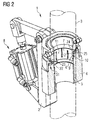
- a locking unit 1 for locking a movable supporting element 2 on a guide element 3.
- the supporting unit 2 is arranged for supporting a device (not shown), or a tool (not shown), which has to be positioned along, and locked on, the guide element 3.
- the guide element 3 comprises a bar having a circular cross section.
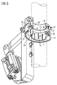
- the locking unit 1 comprises a body 4 fixed to the supporting element 2 and surrounding the guide element 3.
- the body 4 comprises a bore 5 through which the guide element 3 passes in use, i.e. when the body 4 is coupled to the guide element 3.
- the body 4 further comprises a seat 6 arranged for receiving a locking element 7 of the locking unit 1.
- the locking element 7 comprises a further bore 12 through which the guide element 3 passes in use, i.e. when the locking element 7 is coupled to the guide element 3.
- the seat 6 has a conical surface 9.
- the conical surface 9 is an inner surface of the seat 6.
- the locking element 7 has a further conical surface 10 and a locking surface 11, opposite to the further conical surface 10.
- the further conical surface 10 is an outer surface of the locking element 7.
- the locking surface 11 is an inner surface of the locking element 7.
- the further conical surface 10 is arranged for interacting with the conical surface 9.
- the locking surface 11 is arranged for interacting with the guide element 3.
- the locking unit 1 comprises a moving unit 8 for moving the locking element 7 with respect to the seat 6.
- the moving unit 8 moves the locking element 7 between an unlocked configuration, in which the supporting element 2 can slide with respect to the guide element 3, and a locked configuration, in which the supporting element 2 is clamped on the guide element 3.
- the further conical surface 10 does not interact with the conical surface 9 and therefore the locking surface 11 does not contact the guide element 3: in this way, the locking surface 11 does not prevent the supporting element 2 from sliding on the guide element 3.
- the further conical surface 10 interacts with the conical surface 9 and therefore the locking surface 11 contacts the guide element 3: in this way, the locking surface 11 prevents the supporting element 2 from sliding on the guide element 3.
- the locking element 7 has the shape of a ring 13 provided with a plurality of cuts 14, particularly longitudinal cuts, which increase the deformability of the locking element 7, when the further conical surface 10 interacts with the conical surface 9.
- the moving unit 8 comprises a carrying element 15 arranged for carrying the locking element 7.
- the carrying element 15 comprises a still further bore 16 through which the guide element 3 passes in use, i.e. when the carrying element 15 is coupled to the guide element 3.
- the still further bore 16 is coaxial with the further bore 12.
- the carrying element 15 defines an inner cavity 21 that is delimited by a first longitudinal surface 17, i.e. parallel to the lateral surface of the guide element 3, a first radial surface 18, i.e. transversal, perpendicular in the embodiment shown, to the lateral surface of the guide element 3, a second longitudinal surface 19, i.e. parallel to the lateral surface of the guide element 3 and a second radial surface 20, i.e. transversal, perpendicular in the embodiment shown, to the lateral surface of the guide element 3.
- the first radial surface 18 is interposed between the first longitudinal surface 17 and the second longitudinal surface 19.
- the second longitudinal surface 19 is interposed between the first radial surface 18 and the second radial surface 20.
- the first longitudinal surface 17 is a cylindrical surface having a first diameter.
- the second longitudinal surface 19 is a cylindrical surface having a second diameter.
- the first longitudinal surface 17 is coaxial with the second longitudinal surface 19 and the first diameter is greater than the second diameter.
- the moving unit 8 further comprises a retaining element 22 arranged for fixing the locking element 7 to the carrying element 15.
- the retaining element 22 has the shape of a thin disc provided with a central hole 23 through which the locking element 7 passes.
- the retaining element 22 has a first surface 24 that interact with the locking element 22 and a second surface 25 opposite to the first surface 24.
- the retaining element 22 has a plurality of holes, extending between the first surface 24 and the second surface 25. Each one of the above-mentioned holes receives a nut 26 that firmly connects the retaining element 22 to the carrying element 15.
- the retaining element 22 can be firmly connected to the carrying element 15 by other kinds of connecting elements.
- the locking element 7 comprises, in an end zone thereof, a ridge 27, extending outwardly of the further conical surface 10 with respect to a longitudinal axis of the locking element 7.
- the locking element 7 comprises a groove 28 extending inwardly of the further conical surface 10 with respect to a longitudinal axis of the locking element 7.
- the groove 28 is delimited, on one side thereof, by the ridge 27.
- the second radial surface 20 of the carrying element 15, the second longitudinal surface 19 of the carrying element 15 and the first surface 24 of the retaining element 21 define a first chamber 29 that houses the ridge 27 of the locking element 7.
- the second surface 25 of the retaining element 21 and the first lomgitudinal surface 17 of the carrying element 15 define a second chamber 30 that houses an end portion 31 of the body 4.
- the moving unit 8 further comprises a driving element 32 arranged for driving the carrying element 15.
- the moving unit 8 also comprises an actuating element 33 for actuating the driving element 32.
- the driving element 32 comprises a first portion 34 connected to the carrying element 15 and a second portion 35 connected to the actuating element 33.
- the first portion 34 has the shape of a fork and comprises a couple of arms 36 hinged to the carrying element 15 through pins 37.
- the second portion 35 has the shape of a beam and comprises a first end region 38 firmly fixed to the first portion 34, a second end region 39 connected to the actuating element 33 and an intermediate region 40, interposed between the first end region 38 and the second end region 39, hinged to the supporting element 2.
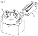
- the actuating element 33 comprises a pneumatic cylinder 41 having a main body 42 hinged to the supporting element 2 and a piston 43 hinged to the second end region 39 of the second portion 35.
- the piston 43 is movable between a retracted position, in which it is received in the main body 42, and an extended position, in which it extends from the main body 42.
- the piston 43 is moved from the retraced position to the extended position.
- the driving element 32 has a side wall 45 comprising a slot 46 having the shape of a cam and arranged for receiving pins 47 connected to the carrying element 15.
- the driving element 32 is connected to the piston 43 so that the driving element 32 can rotate around a longitudinal axis thereof.
- the locking unit for locking a movable supporting element on a guide element that has a simple structure. Due to the coupling of the conical surface and the further conical surface, in fact, the locking unit can be easily moved from the locking configuration to the unlocking configuration, and vice versa.
- the locking unit is very strong and therefore able to bear heavy loads.
Landscapes
- Engineering & Computer Science (AREA)
- General Engineering & Computer Science (AREA)
- Mechanical Engineering (AREA)
- Snaps, Bayonet Connections, Set Pins, And Snap Rings (AREA)
Priority Applications (1)
| Application Number | Priority Date | Filing Date | Title |
|---|---|---|---|
| EP16154188.3A EP3203090A1 (de) | 2016-02-04 | 2016-02-04 | Sperreinheit |
Applications Claiming Priority (1)
| Application Number | Priority Date | Filing Date | Title |
|---|---|---|---|
| EP16154188.3A EP3203090A1 (de) | 2016-02-04 | 2016-02-04 | Sperreinheit |
Publications (1)
| Publication Number | Publication Date |
|---|---|
| EP3203090A1 true EP3203090A1 (de) | 2017-08-09 |
Family
ID=55345689
Family Applications (1)
| Application Number | Title | Priority Date | Filing Date |
|---|---|---|---|
| EP16154188.3A Withdrawn EP3203090A1 (de) | 2016-02-04 | 2016-02-04 | Sperreinheit |
Country Status (1)
| Country | Link |
|---|---|
| EP (1) | EP3203090A1 (de) |
Cited By (1)
| Publication number | Priority date | Publication date | Assignee | Title |
|---|---|---|---|---|
| EP4553323A1 (de) * | 2023-11-09 | 2025-05-14 | Nabtesco Corporation | Aktuatoreinheit |
Citations (8)
| Publication number | Priority date | Publication date | Assignee | Title |
|---|---|---|---|---|
| GB775743A (en) * | 1954-11-10 | 1957-05-29 | P S C Equipment Ltd | An improved device for clamping around metal wire or rod |
| US2830788A (en) * | 1954-09-10 | 1958-04-15 | United States Steel Corp | Pushing and pulling apparatus |
| GB893294A (en) * | 1958-07-04 | 1962-04-04 | Elizabeth Seppeler | Hydraulic lifting gear |
| CH496510A (fr) * | 1969-08-07 | 1970-09-30 | Charmilles Sa Ateliers | Dispositif de commande des déplacements d'une électrode dans une machine à usiner par électro-érosion |
| EP0103555A1 (de) * | 1982-08-20 | 1984-03-21 | Atlas Copco Aktiebolag | Verriegelungsvorrichtung für einen Kolben |
| EP1813823A2 (de) * | 2006-01-31 | 2007-08-01 | SITEMA GmbH & Co. KG | Klemmvorrichtung |
| KR100883882B1 (ko) * | 2008-06-23 | 2009-02-18 | 한국뉴매틱(주) | 로드부재의 에어 록킹장치 |
| EP2213884A1 (de) * | 2009-02-02 | 2010-08-04 | SITEMA GmbH & Co. KG | Klemmeinheit und Verfahren zum Überwachen der Klemmkraft bei einer solchen |
-
2016
- 2016-02-04 EP EP16154188.3A patent/EP3203090A1/de not_active Withdrawn
Patent Citations (8)
| Publication number | Priority date | Publication date | Assignee | Title |
|---|---|---|---|---|
| US2830788A (en) * | 1954-09-10 | 1958-04-15 | United States Steel Corp | Pushing and pulling apparatus |
| GB775743A (en) * | 1954-11-10 | 1957-05-29 | P S C Equipment Ltd | An improved device for clamping around metal wire or rod |
| GB893294A (en) * | 1958-07-04 | 1962-04-04 | Elizabeth Seppeler | Hydraulic lifting gear |
| CH496510A (fr) * | 1969-08-07 | 1970-09-30 | Charmilles Sa Ateliers | Dispositif de commande des déplacements d'une électrode dans une machine à usiner par électro-érosion |
| EP0103555A1 (de) * | 1982-08-20 | 1984-03-21 | Atlas Copco Aktiebolag | Verriegelungsvorrichtung für einen Kolben |
| EP1813823A2 (de) * | 2006-01-31 | 2007-08-01 | SITEMA GmbH & Co. KG | Klemmvorrichtung |
| KR100883882B1 (ko) * | 2008-06-23 | 2009-02-18 | 한국뉴매틱(주) | 로드부재의 에어 록킹장치 |
| EP2213884A1 (de) * | 2009-02-02 | 2010-08-04 | SITEMA GmbH & Co. KG | Klemmeinheit und Verfahren zum Überwachen der Klemmkraft bei einer solchen |
Non-Patent Citations (1)
| Title |
|---|
| JAMALY F: "SICHERHEITSKONZEPTE FUER OELHYDRAULISCHE HUBWERKE. ÖTEIL I: KONVENTIONELLE SICHERUNGSMECHANISMEN GEGEN UNBEABSICHTIGTES ABSINKEN UND IHRE THEORETISCHE BEWERTUNG", 1 January 1996, O & P - OELHYDRAULIK UND PNEUMATIK: ZEITSCHRIFT FUER FLUIDTECHNIK, AKTORIK, STEUERELEKTRONIK UND SENSORIK, VEREINIGTE FACHVERLAGE GMBH, DE, PAGE(S) 57 - 62, ISSN: 0341-2660, XP000195395 * |
Cited By (1)
| Publication number | Priority date | Publication date | Assignee | Title |
|---|---|---|---|---|
| EP4553323A1 (de) * | 2023-11-09 | 2025-05-14 | Nabtesco Corporation | Aktuatoreinheit |
Similar Documents
| Publication | Publication Date | Title |
|---|---|---|
| CN107076193B (zh) | 输出装置 | |
| US10195476B2 (en) | Weight bar and locking collar | |
| EP3408054B1 (de) | Vorrichtung zum verriegeln von teilen auf werkzeugmaschinen | |
| CN104908050B (zh) | 用于操纵器的联接装置 | |
| US8286971B2 (en) | Holding fixture | |
| US20080232898A1 (en) | Lock pin with pushbutton-operated axial locking and free bearing | |
| JP2023502455A5 (de) | ||
| JP2019517395A5 (de) | ||
| US10144116B2 (en) | Clamping device for clamping a workpiece and processing table with a clamping device | |
| US20140314505A1 (en) | Multi-position hole saw assembly with plug ejector | |
| US10465737B2 (en) | Quick lock assembly | |
| US11649847B2 (en) | Screw able device with retractable thread sections | |
| EP3278745A3 (de) | Adapteranordnungen für chirurgische vorrichtungen | |
| EP3203090A1 (de) | Sperreinheit | |
| CN114391068A (zh) | 用于家具搁板的完善的支撑装置 | |
| US8123428B2 (en) | Method and apparatus for locking telescoping members | |
| US6634826B1 (en) | Clamp for support and connection members | |
| US11097355B2 (en) | Clamping chuck with inclined slides | |
| CN106715051B (zh) | 利用与角传动装置一起使用的楔形件的夹持系统 | |
| US20130193281A1 (en) | Releasable locking connector | |
| US8267390B2 (en) | Locking mechanism and reconfigurable clamp incorporating the same | |
| JP2021526968A (ja) | 遠心分離機 | |
| EP3208041B1 (de) | Lokalisierungsbolzenbaugruppe | |
| US20150002151A1 (en) | Mounting for a Body Coil of a Magnetic Resonance Device | |
| JP2018176314A (ja) | ロボットアームのカップリング装置 |
Legal Events
| Date | Code | Title | Description |
|---|---|---|---|
| PUAI | Public reference made under article 153(3) epc to a published international application that has entered the european phase |
Free format text: ORIGINAL CODE: 0009012 |
|
| STAA | Information on the status of an ep patent application or granted ep patent |
Free format text: STATUS: THE APPLICATION HAS BEEN PUBLISHED |
|
| AK | Designated contracting states |
Kind code of ref document: A1 Designated state(s): AL AT BE BG CH CY CZ DE DK EE ES FI FR GB GR HR HU IE IS IT LI LT LU LV MC MK MT NL NO PL PT RO RS SE SI SK SM TR |
|
| AX | Request for extension of the european patent |
Extension state: BA ME |
|
| STAA | Information on the status of an ep patent application or granted ep patent |
Free format text: STATUS: THE APPLICATION IS DEEMED TO BE WITHDRAWN |
|
| 18D | Application deemed to be withdrawn |
Effective date: 20180210 |